

Keystoker K-2, K-6 Operating Instructions And Maintenance Manual

K-2 & K-6 Direct Vent
Operating instructions and maintenance enclosed
Thoroughly read and understand instructions
Always leave this manual with stove owner
Follow the instructions within this manual. If instructions are not
followed, a fire may result causing property damage, personal injury, or
even death.
A carbon monoxide detector has been supplied with your stove. You must
plug it in.
Danger risk of fire or explosion. Do not burn garbage, gasoline, drain oil,
or other flammable liquids. Do not use chemicals or fluids to start fire.
Burn rice anthracite coal only
Stoves surfaces may be hot while in operation. Keep children away. Do
not touch during operation
Do not connect this unit to a chimney flue serving another appliance.
Follow all local building and Zoning ordnances

K-2 and K-6 DIRECT VENT with FLATGRATE UNIT
KEYSTOKER BOILER INSTLLATION INSTRUCTIONS
Through these instructions we will try to guide you on a step by step procedure for installing,
adjusting and operating of your new KEYSTOKER stoker boiler unit.
Selection of location. Keystoker boilers are available with fire door on the right or left side.
When you stand at the stoker end of the boiler and look directly over top of boiler toward stack
end, you may choose to have a fire door on the right or left side of boiler. Selecting a position
to make this door accessible is important. When door side must be placed toward a wall, 30”
clearance is recommended for easy fire and ash door access. Clearance from wall at stack end
should be 18” to permit removal of water heating coil if necessary. Clearance on blank and
hopper sides should be 6”.
Setting up boiler. Place boiler in desired position. We strongly recommend placing steel
shims or bricks under each corner of boiler to allow an air space, to prevent moisture from
accumulating and rusting base of boiler. Using a level, plumb stoker end of the boiler, adding
steel shims as necessary to plumb the stoker end of the boiler. Failure to do this will change
pitch on stoker unit and may have adverse effects when burning coal. Again with level, check
top of boiler from side to side, adding shims as necessary to level boiler. Do not place shims
completely under boiler. Allow 1” to 2” of shims to extend out from under the boiler. Shims
will then be used as a base to rest insulated jacket upon.
Supply & Return piping system. The top of you boiler has at least 4 openings. The largest
opening is the feed line to your radiation. Since this outlet has a drop tube welded inside the
boiler, you must use if for your radiation supply line. Even thou it may be necessary to bush
down to a smaller size, we recommend starting with 1 ¼” pipe and installing a 1 ¼” x 1 ¼” x 1”
tee in supply line to be used for a by-pass loop. (You may now make your piping connections
from feed outlet on boiler to flow valve.
You may use either of the large openings on the bottom of the stack end of the boiler as your
return. Select the side that will allow convenient access to the circulator for future servicing.
Install return piping and circulator, again referring to (Installation Diagram Pg 7) for location
of by-pass loop. Your 1 ¼” x 1 ¼” x 1” tee must be installed below circulator. (See Installation
Diagram Pg 6).
Install by-pass loop as per (Installation Diagram pg 6) with 1” pipe size. Place a tee 1’ x ½” F x
1” in by-pass loop to allow installation of immersion well for the 4006B Honeywell Hi Limit
control to extend into full water flow.
1

K-2 and K-6 DIRECT VENT with FLATGRATE UNIT
KEYSTOKER BOILER INSTLLATION INSTRUCTIONS
Over 50 years of installation experience has proven to us that the above mentioned by-pass loop
is absolutely necessary for optimum performance of your heating system .
Install a boiler drain valve in the large opening at the bottom of boiler. Install a male adapter in
boiler on opposite side of boiler drain before installing stack end of boiler see diagram pg 6
Boiler feed and domestic water piping. Refer to diagram pg 8
Install ½” male adapter in both fittings on domestic water coil. Install a ½” male adapter in the
½ “ fittings on the top of the boiler to be used for a boiler water feed. Solder a 7” long piece of
pipe into boiler pipe fitting. Before installing stack end of jacket
Note: Before proceeding with connections for piping of boiler return and domestic water
Install stack end of insulated jacket Now. Then you may proceed with completion of domestic
piping and instillation of necessary valves.
Install a domestic water mixing valve, we recommend a Honeywell AM-1 series not included
with boiler install as per manufactures instructions (See Diagram Pg 6).
If an automatic fill valve is desired, install as per manufacture’s instructions.
Install a PH 5 expansion tank on the domestic mixed water line as per manufactures instructions
Installation and piping of accessories: A ¾” 30 lb. AMSE approved relief valve must be
installed in ¾” fitting on top of boiler, turning discharge to the side and hard pipe it to 3” above
floor (See Diagram Pg 6).
Install altitude gauge (temperature/ pressure gauge).
Connect expansion tank directly to remaining fittings on top of the boiler, NOT to any other
part of the heating system. Install a 1/2 ” ball valve in pipe going to expansion tank with
direction marker on valve pointing toward the expansion tank.
Install immersion well for low water cut off, in ¾” fitting on side of boiler above fire door in
lower hole closet to unit end of boiler.
Install immersion well for Triple Aquastat, in ¾’ fitting on side of boiler above fire door in
upper hole.
Place fire door into boiler opening and secure by tightening screws in frame of fire door. Seal
fire door with high temp. Silicone or furnace cement. Install spring handle on fire door handle
2

K-2 and K-6 DIRECT VENT with FLATGRATE UNIT
KEYSTOKER BOILER INSTLLATION INSTRUCTIONS
by bending spring handle open and put it through hole in handle on fire door and squeezing it
closed.
Jacket and stoker installation: Install hopper end of jacket, then blank side, then fire door
side, secure with #8 x 1 sheet metal screws provided. Install jacket top and secure with #8 x 3/8
sheet metal screws.
Stoker units are shipped entirely assembled. Lift stoker into opening, bottom of a stoker has a
¼” rod welded in place which must go inside the stoker opening. Place a thick smear of furnace
cement or high temp. Silicone on flange of stoker and tilt into place, securing with 3/8 x 1 ¼
machine screws, washers, and nuts as provided.
Set hopper into place. The hopper bottom should lap over stoker throat approximately 1”. Since
one hopper is use for several size stokers, it may be necessary to trim the opening. Bend flange
down to fit inside throat of stoker – be sure mechanism is free to operate.
Control installation and electrical wiring: Install triple aquastat into its well being careful
not to kink the thin capillary tube. Install low water cutoff onto its well. Screw timer to jacket
next to the triple Aquastat (See Diagram Pg 6).
Install 4006B hi limit into well in by-pass loop. Your stoker must be on its own circuit. From
main breaker to boiler use 12-2 wire with ground on a 20 amp breaker. Follow wiring diagram
and any applicable UL and local code
If pipe must be run inside of house, we strongly recommend using a tee with cap instead of
elbow at bottom of riser pipe. You must seal all joints using high temperature silicone see page
10 if going through a combustible wall.
Safety inspection of a venting system should be performed before and after installing your new
stove. Procedures to follow are those recommended by National Fuel Gas Code, ANSI Z223.1
or refer to local codes or ordinances.
Plan the vent system layout before installation to avoid possibility of accidental contact with
concealed wiring or plumbing inside walls.
Plumb hopper end of stove with level. Mount hopper in place and fasten securely. Reach down
into bottom of inside hopper and bend flange of hopper into throat of stoker.
After determining location of stove, (if you are going through a frame wall) cut a hole through
exterior wall slightly larger than the 6” black pipe. Put stove into position to determine stove
pipe length needed to have at least 6” of pipe extending past exterior wall.
3

K-2 and K-6 DIRECT VENT with FLATGRATE UNIT
KEYSTOKER BOILER INSTLLATION INSTRUCTIONS
From outside of home, insert 4” stainless steel pipe through opening in wall, … through #5
blank plate and through #4 (which is the 6” cap with 4” hole)… and slide pipe over exhaust air
tube. Secure with screw. Seal pipe with high temperature silicone or equivalent. Secure #7
screened plate to outside wall. See pg 11.
It is not necessary to use 6” black pipe if 4” pipe is going through a non-combustible wall, such
as concrete or block. No barometric draft control is required
On outside of home, place 4” stainless steel tee on exhaust pipe. Place 4” stainless steel rain
cap on top of 4” tee. Secure with screws. Leave bottom of stainless tee open.
Depending on location of exhaust venting to outdoors, varying draft and wind conditions may
cause occasional tripping of reset button, causing fire to go out.
Draft and air intake settings are preset at factory and it is usually not necessary to change for
installation going straight out through the wall. It is still recommended to check draft settings
with draft gauge after starting fire.
If extra stove pipe must be added inside home to achieve necessary height to go above outside
grade level, it may be necessary to adjust combustion air intake shutter located on combustion
motor, to achieve proper draft setting of -.02
Initial start up: Fill system by opening boiler feed valve. Open air vents on radiation one at a
time until air is removed from system. Normal operating pressure on most heating systems is
between 10 and 20 PSI. Automatic fill valves are factory set at 12 PSI. If an automatic fill
valve is not used, then boiler feed valve must remain in normally closed position.
Open valve supplying water to domestic hot water coil, this valve must remain in the normally
open position.
Starting coal fire: DO NOT USE ACCELERANT SUCH AS: as gasoline, lighter fluid, or
kerosene, etc. Use dry coal only. Put coal in hopper. By reaching through fire door, pull coal
down to cover entire grate. Crush several charcoal briquettes into smaller pieces, crumble
newspaper and dig it through the coal, so it touches the grate. Lay charcoal on top of
newspaper. Turn switch on. When charcoal turns red, place a few hands full of coal on top of
charcoal. If fire moves toward bottom of grate before fire is established, coal feed can be
slowed down by turning red nut CCW or by flipping feed bolt to a sideward position.
4

K-2 and K-6 DIRECT VENT with FLATGRATE UNIT
KEYSTOKER BOILER INSTLLATION INSTRUCTIONS
After starting coal fire: Allow stove to warm up. With air shutter on combustion blower is
about ½ open Insert draft guage through pre-drilled hole in the upper portion of the fire door.
Adjust draft to a -.02 at full fire. Draft is adjusted on venter by opening or closing the t handle
shutter. (see diagram page 10)
To obtain a more complete burn of the coal, the combustion motor is designed for continuous
run.
When there is no demand combustion motor will continue to run and cause the coal already on
the grate to burn. Rather than to allow the coal to smolder and die out in an unburnt condition.
This will achieve a cleaner ash, and allow more heat to be produced and absorbed into heating
system.
During the summer months of operation the small combustion motor will force a small amount
of air going through the grates at all times, which will cause ash to become like powder. It also
prevents the fire from going out. At the same time, it reduces the size of the fire bed to
approximately 1 ½ to 2 which will prevent boiler water from becoming overheated.
Proper size of fire is obtained by turning white feed nut on pusher bar clockwise for more feed
and counterclockwise for less coal feed.
Location and final placement for white nut will be determined by size of coal you purchase.
For rise coal, the white nut might be turned down 5 to 6 turns for maximum setting, whereas,
for buckwheat coal the white nut might be only be turned down 3 to 4 turns for maximum
setting
During winter operation hot coals should never be pushed off the end of grate. This indicates
that the coal feed needs to be reduced or if during winter operation the fire bed is too small
increase coal feed.
After coal feed adjustment is completed, if during the summer the water is too hot..DO NOT
ADJUST THE COAL FEED reduce timer only. If fire goes out DO NOT ADJUST COAL
FEED increase timer only
5
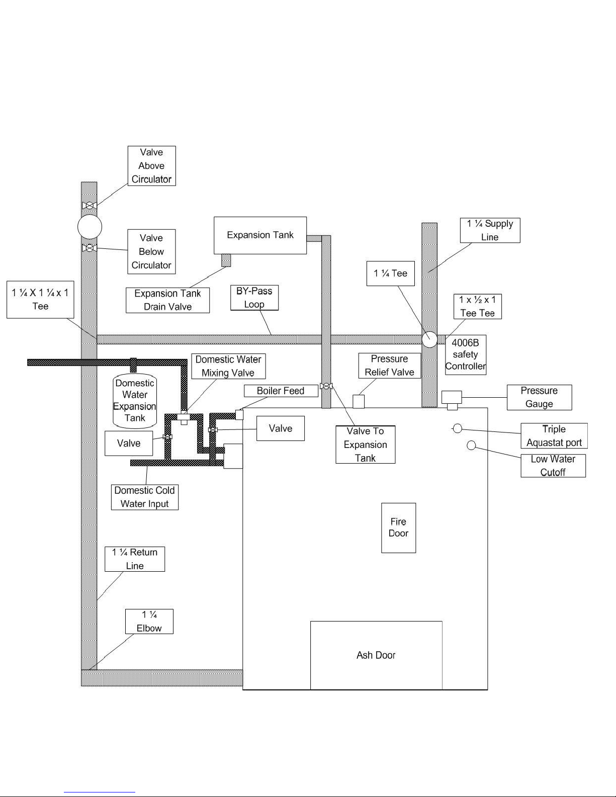
K-2 and K-6 DIRECT VENT with FLATGRATE UNIT
KEYSTOKER BOILER INSTLLATION INSTRUCTIONS
Side View
6
 Loading...