

Keystoker A-250, A-450, A-350 Operating Instructions Manual

A-250, A-350, & A-450 Warm Air Furnace
Operating instructions and maintenance enclosed
Thoroughly read and understand instructions
Always leave this manual with stove owner
Follow the instructions within this manual. If instructions are not
followed, a fire may result causing property damage, personal injury, or
even death.
A carbon monoxide detector has been supplied with your stove. You must
plug it in.
Danger risk of fire or explosion. Do not burn garbage, gasoline, drain oil,
or other flammable liquids. Do not use chemicals or fluids to start fire.
Burn rice or buckwheat anthracite coal only
Stoves surfaces may be hot while in operation. Keep children away. Do
not touch during operation
Do not connect this unit to a chimney flue serving another appliance.
Follow all local building and Zoning ordnances

INSTALLATION INSTRUCTIONS FOR A-250, A-350, & A-450
1. Place furnace floor (located in carton marked top A-450 are shipped
separate) on a flat level surface. The end of floor without angle is stokerhopper end.
2. Floor without opening is the stack end and should be placed in the
direction of the chimney.
3. Stand furnace on furnace floor and center it from side to side. Front of
furnace must be even with edge of furnace floor. Ash door frame will
extend beyond end of the floor.
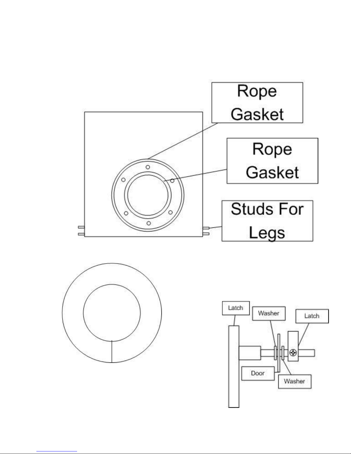
4. Install flat rope gasket around furnace exhaust flange (gasket is supplied
in ash tub).
5. Connect heat exchanger to furnace. Make sure that the stack and cleanout
outlets are in their lowest position. Tighten nuts securely in an alternative
diametric patter to slightly compress the rope seal between flanges.
6. Install (4) heat exchanger legs (rear legs are cut on an angle) (A-250 only
has 2 rear legs). After connecting heat exchanger and furnace with bolts,
front legs MUST be removed from heat exchanger.
7. Place front blank side panel of jacket in floor slot and in the slot on the
front face plate of furnace.
8. Install rear blank side panel of jacket into floor slot and screw fast using
screws found in jacket top box.
9. Find bottom partition in top box (silver piece with square hole in it, found
in top bow) pry open S cleat bend on the top end of partition. Slide bottom
partition (silver piece with square hole in it behind angle on rear panel of
the jacket piece just installed But do not secure with screws until step 11.
10. Install door front panel of jacket using same procedure as opposite side
panel.
11. Install door rear panel using same procedure as rear blank panel and
secure using same type of screws found in top box .
1

INSTALLATION INSTRUCTIONS FOR A-250, A-350, & A-450
12. Place stack bib over stack and clean out ports and fasten with screws.
13. Install blank plate over unused fire door hole in the jacket.
14. Crawl under heat exchanger and slide bottom partition against angles on
inside of jacket. Drill 1/8” holes and secure with screws.
15. Take hopper support bar off of bolts on front of furnace and set aside.
16. Install front hopper bib, by sliding angle on bottom of bib, into slot on
furnace plate.
17. Then drill four 1/8” holes through predrilled holes in hopper bib sheet and
secure with sheet metal screws provided in jacket top box.
18. Find top partition (silver piece in the top box with a half circle cut out).
Reach over top of jacket, place top partition into S cleat bend on the top of
bottom partition. Don’t secure now.
19. Place jacket top over jacket side panels being sure filter rack is over heat
exchanger, and secure with screws. (A-450,000 jacket top has two
sections). Install screws through top partition into angle protruding down
off of jacket top.
20. Plenums may now be installed.
21. Install handles on blower door. Insert handle through hole in blower door.
Drive perforated locking washer tight up against fan door, place latch on
handle and tighten screw in latch.
22. It may be necessary to adjust stack bib up or down to allow fan door to
close and seal properly.
Center fire door, in opening provided, and drill 1/8” holes (1 in top of door frame
and 1 in bottom of door frame). Put a light smear of furnace cement or high
temperature silicone around fire door opening before installing fire door. Furnace
cement or high temp silicone not included. Then fasten door with two self- drilling
screws, provided in ash tub. Install spring handle on fire door. Bend hook open on
2

INSTALLATION INSTRUCTIONS FOR A-250, A-350, & A-450
spring handle and thread it through predrilled hole in fire door handle. Then rebend spring handle closed. Also found in ash tub.
Fasten jacket panels to floor slot and top slot, by drilling 1/8” holes and securing
with sheet metal screws. (Install screws whenever necessary to insure quiet
operation during convection blower cycles).
Install hanging baffles: reach in through stoker unit opening, and hang small baffle
(found in the furnace A-450 does not have a small baffle) over opening entering
into heat exchanger. Then by reaching in through stoker unit opening, hang large
baffle on angles that are welded inside furnace.
Before installing stack pipe, slide rings with screws over stack outlets, and slide
against rear bib. Tighten screws.
Place galvanized cap over exhaust port that is not going to be used for chimney
connection.
Assemble blower- Fasten left and right legs to blower housing. Place rubber
grommets in holes of legs. Place the slotted motor mount bracket on blower
housing and secure with screws. Slide two square head bolts into channel of motor
mount. Place bracket of fan motor over square head bolts and loosely place buts
and bolts. Install large pulley on blower shaft, and small pulley on motor shaft.
Mount belt adjustment angle on fan motor bracket. Place belt over both pulleys.
Align pulleys. Then tighten pulleys motor mounts (See instructions found with
blower). Slide blower into blower cavity. CAUTION: DO NOT PUSH
BLOWER BEYOND CENTER PARTITION.
IMPORTANT: Blower belt must be somewhat loose. Making belt too tight will
cause excessive and rapid wear on sleeve bearing in both blower and motor.
Blower is freestanding and does not need to be bolted to furnace floor.
Slide filter(s) into filter bracket on return end of furnace.
Slide ash door down over hinge pins.
Install a light smear of furnace cement or high temperature silicone. Remove and
dispose of shipping screw from gear box. Stoker units are shipped completely
assembled. Lift stoker into opening, stoker bottom has ¼” rod welded in place
3

INSTALLATION INSTRUCTIONS FOR A-250, A-350, & A-450
which must go inside stoker opening. Place a thick smear of furnace cement on
flange of stoker and tilt into place. Secure with 3/8 x 1 ¼” machine screws,
washers, and nuts.
Place hopper on stoker unit. Place hopper support bar in hopper on bolts and fasten
hopper and support bar (A-250s do not have support bar) to furnace with large
sheet metal washers and nuts. Hopper bottom should lap over stoker throat
approximately 1”. Since same hopper is used with different stokers, it may be
necessary to trim opening of bottom of hopper. Bend flange down to fit inside of
throat of stoker to be sure feed mechanism is free to operate.
Mount Timer and Relay harness on Furnace Jacket (see diagram on pg7). Cut 7/8”
opening in supply plenum chamber to install Fan Limit control and secure with
screws.
Connect 115 volt power supply to switch, black wire gets connected to open screw
on switch, white wire gets wire to single white wire in switch box.
Wire furnace following wiring diagram and any applicable UL, or local codes.
Furnace must be on its own 20 amp circuit.
Locate thermostat in an area where heat from furnace can free be reached. Mount
plastic wall plate of thermostat. Connect thermostat wires to screws on lower portion
of wall plate. Run thermostat wires to relay on furnace and connect wires to
terminals marked T.T. (note color coding is unimportant).
After making electrical connections, turn blower on. Be sure blower is running
proper direction. To change blower direction, follow blower instructions on blower
motor or install motor on opposite side of blower Wire stoker unit and convection
blower also
After making electrical connections, turn blower on. Be sure blower is running in
proper direction. Mount motor on left or right side of blower will cause blower to
run CW or CCW. To change direction, follow instructions on motor. (See diagram
on motor plate for changing direction)
INSTALLING STACK PIPE: Heat exchanger has two stack outlets. Either one
may be used to connect stove pipe to chimney. The other opening must be capped
and is to be used for a clean out during maintenance. We recommended that you
use the outlet closest to chimney for stack. It is important to run full size stack
from furnace to thimble in chimney. If stack pipe must be reduced it needs to be
4
INSTALLATION INSTRUCTIONS FOR A-250, A-350, & A-450
reduced at chimney thimble. Install barometric draft control in first full section of
stack closest to furnace. Follow instructions packed with draft control, making
sure draft control bearings are level and face of control is perpendicular to floor.
Rings
5

INSTALLATION INSTRUCTIONS FOR A-250, A-350, & A-450
6
 Loading...