

Keystoker 90, 000 BTU, 105, Koker, Econo 90 Installation, Operation And Maintanance Manual
...
105K BTU Stove Shown
Installation, Operation and Maintenance
Manual
90,000 BTU & 105,000 BTU
Stoker Coal Stoves, Direct Vent
© October 2017 REV 2

Keystoker – Schuylkill Haven, PA 17972 90,000 BTU & 105,000 BTU Stoker Coal Stoves, Direct Vent
CONAM Inspection, Inc.
Auburn, MA 01501 STL-002
About Us
Keystoker had its inception in 1946.
Two electrical engineers saw the need for a way to con ven i en tly burn anthracite coal,
which was plentiful, but heating with coal had a bad reputation of being dirty and
requiring maintenance several times a day . O ur en gineers developed an automatic
stoker unit equipped w ith a co al hopper that held enough fuel for several days. This
allowed the coal to be cleanly burned and without fr equent maintenance. T hey t h en
saw the need to make a hot water boiler specifically des ign ed to burn coal and built
them in multiple sizes t o m eet o ur cu st o m ers' needs.
As prices of energy co nt inued to escalate, Keystoker continued its research. Over 60
years of research has de veloped a patented feed-in sy stem , a patented flat grate, and
a patented thermal heat exchange, which has produced the highest efficiency
possible.
Keystoker --- Made in America with American Technology and utilizing American
resources is now know n internationally for its simplicity , quality, an d dependab ility, all
this and still an economical price.
TESTED 9/89 TO ANSI/UL 1482, CSA B366-m1979 & ETLM 78-1
© October 2017 REV 2 - 2 -

Keystoker – Schuylkill Haven, PA 17972 90,000 BTU & 105,000 BTU Stoker Coal Stoves, Direct Vent
Safety
4
Precautions & Definitions
4
General Safety Statements
4
Installation
5
Stove Placement
5
Vent Terminator Locat ion & Direct Vent Arrangem en t
7
Direct Ve nt Completion Kit
9
Assembly
10
Fuel Type
11
Operation
12
Start-up
12
Diagram 1 - Continuou s Heating
14
Diagram 2 – Intermittent Heating
15
Component Descriptions & Operation
16
Stoker Unit Components
16
Timer
19
Thermostat
20
Fan Limit Switch
20
Maintenance
21
Cleaning & Lubrication of Stove
21
Reassembly of Direct V ent Piping
22
Cleaning Stove Glass
23
Ash Pan Emptying
24
Gear Motor Removal & Insta l lation
25
Troubleshooting Guide
27
Diagrams
29
Wiring
29
Wiring – Direct Vent
30
Stove Parts List
31
Fire Door & A sh Door Parts Lists
32
Warranty
33
Stove Information
33
Parts Ordering
33
Stove Contents Checklist
34
Table of Contents
© October 2017 REV 2 - 3 -
Keystoker – Schuylkill Haven, PA 17972 90,000 BTU & 105,000 BTU Stoker Coal Stoves, Direct Vent
Safety
Precautions & Definition s
Our stoves have been designed fo r sa f e and reliable operation when properly used
and maintained in accordance with instructions contained in this manual. A stoker
stove is a precision system that if not properly installed or maintain ed can be hazardous,
cause burns, electrical shock or even loss of life. Keystoker shall not be liable for
physical injury, damage to property or death caused by a failure to obse rve the
instructions in this man u a l.
Please note the follow i n g sy m bo l s are used to denote special atten tion within this
manual:
Electrical Hazard. Particular care must be t aken when electrical power source to
the unit is energized.
Warning. Operating procedure, practice etc. which, if not correctly followed,
could result in personal in jury .
Caution. Operating procedure, practice etc. which if not fo llowed could result in
damage or destruction of unit.
Fire. Operating procedure, practice, etc. which if not followed could result in
severe burns, bodily harm, loss of life and property damage.
Death. Critical situation or operation o f u nit that may cause death.
General Safety Statements:
• Thoroughly read and understand all instructions
• Always leave this manu al with the owner of the stove.
• A carbon monoxide (CO) detector has been supplied with your sto ve.
o The CO Detector needs to be plug ged in.
o CO is colorless, odorless & tasteless gas that can be dead ly if not
monitored or detected properly.
• Danger risk of fire or explosion. Do not burn garbage, g asoline, drain oil, or other
flammable liquids. Do not use chemicals or fluids to start fire.
• Stove surfaces may be h o t w h ile in op eration. Keep children aw ay . Do not touch
during operation
• Do not connect this unit to a chimney flue serving anoth er appliance
• Please follow all local bui lding and zoning ordinances
• Use the proper fuel typ e as no t ed in t his manual
© October 2017 REV 2 - 4 -
Keystoker – Schuylkill Haven, PA 17972 90,000 BTU & 105,000 BTU Stoker Coal Stoves, Direct Vent
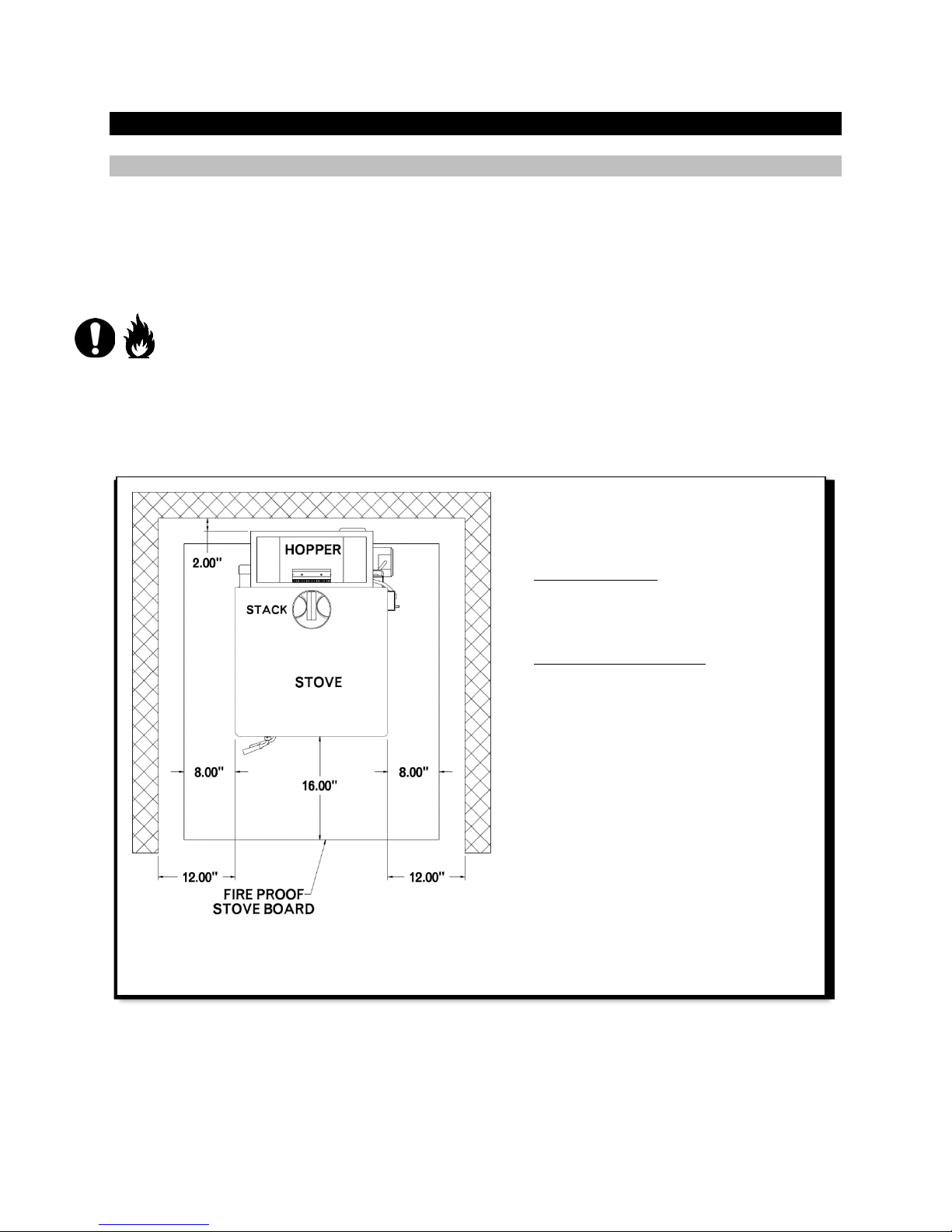
FIGURE 1a
• Tested 9/89 to ANSI/UL 1482, CSA
Stove Placement
1. Safety inspection of a ven ting system should be performed before and after
installing your new stove. Procedures to follow are those recommended by
National Fuel Gas Code, ANSI Z223.1 or refer to local cod es or o rdinances.
2. Plan the vent system layout before installation to avoid possibility of accidental
contact with concealed wiring or plumbing inside walls.
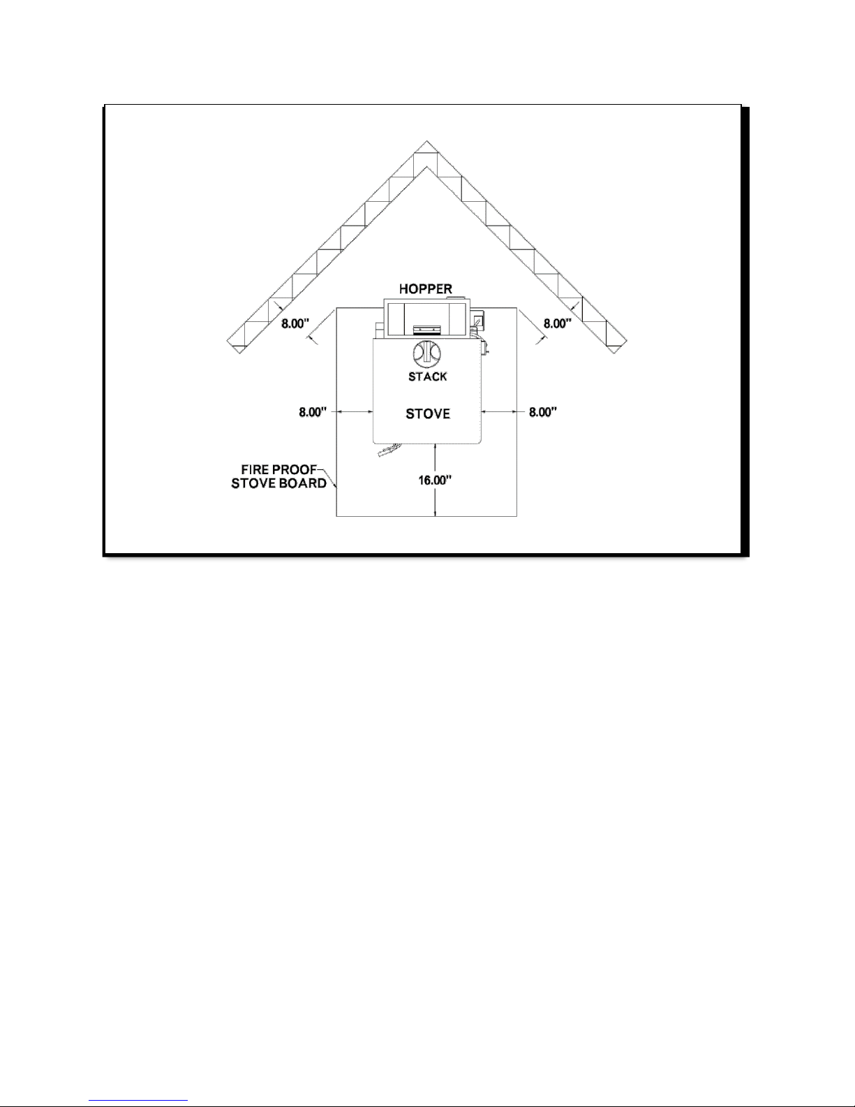
3. Select a position on a solid le vel s u rface with direct access t o a chimney. On
non-masonry floors, use an approved fireproof floor protector under stove.
Maintain 12” clearance on sides of stove to combustibles. Maintain 6” clearance
from 4” pipe to combustible. Clearance from 6” black wall pass thru pipe is 0” to
combustibles. A 2” clearance on rear and 16” clearance on front of stove.
Clearance from corne rs of stove is 8”. See label on sto ve. Refer to Figure 1a &
1b.
Installation
B366-m1979 & ETLM 78-1
• Chimney Type: Minimum 6”
diameter approved low heat
residential type all fuel.
• Chimney connector: 6” diameter
24 gauge blue or black steel.
• Install at least 18 inches from
ceiling. Special meth ods are
required when passing through a
wall or cei ling.
© October 2017 REV 2 - 5 -
Keystoker – Schuylkill Haven, PA 17972 90,000 BTU & 105,000 BTU Stoker Coal Stoves, Direct Vent
FIGURE 1b
© October 2017 REV 2 - 6 -

Keystoker – Schuylkill Haven, PA 17972 90,000 BTU & 105,000 BTU Stoker Coal Stoves, Direct Vent
FIGURE 2
A B C
H E F D G
Note: Lettered dimen sions refer to above list
Vent Terminator
Vent Terminator Location & Direct Vent Arrangement
VENT TERMINA TOR MAY NOT BE LOCATED
A. Less than 1 foot above grad e.
B. Above or within 3 feet horizontally of oil tank or gas meter.
C. Closer than 3 feet to insid e corner of home.
D. Closer than 1 foot from any opening that gass es could re-enter home.
E. Less than 4 feet below windows.
F. Less than 1 foot horizontally of door or window.
G. Less th an 3 feet above any forced air inlet located within 10 feet.
H. Less than 7 feet above grade when adjace n t to pu bl ic walkways
Refer to Figure 2
© October 2017 REV 2 - 7 -

Keystoker – Schuylkill Haven, PA 17972 90,000 BTU & 105,000 BTU Stoker Coal Stoves, Direct Vent
FIGURE 3
Bottom Vent Layout
Top Vent Layout
Note: Item descriptions on next page
Note: Item descriptions on next page
© October 2017 REV 2 - 8 -

Keystoker – Schuylkill Haven, PA 17972 90,000 BTU & 105,000 BTU Stoker Coal Stoves, Direct Vent
Item #
Component
Item #
Component
1*
Sealer for All Joints
5*
4” Tee
2
Stove
6
1 Piece Wall Kit
3
Hanging Baffle
7
Stainless Steel Rain Cap
4*
Direct Vent Unit
8
4” Elbow
Item #
Component
Item #
Component
1
Direct Vent Exhaust Motor
5
4” Elbow
2
Direct Vent Unit
6
4” Stainless Steel Pipe
3
4” Stainless Steel Pipe
7
6” 24 Ga. Stainless Pipe
4
4” Tee
8
Stainless Steel Rain Cap
FIGURE 4
Direct Vent Completion Kit
Supplied wit h S tove
Note: Orientation of Direct
1*
Seal All Joint s : When it becomes necess ary to run exhaust pipe up the interior
wall of home, every joi nt m ust be sealed with a high temperat ure silicone or
equivalent. This will prevent fumes from escaping into home.
4* Draft Port: It may be necessary to clean draft port (Located inside exhaust
outlet of the Direct Vent Unit) every several weeks to keep the stove from tripping
out on safety reset. Removal of the Direct Vent side plate wi ll aide in cleaning.
Using brush (furnished with stove) remove ash pan, reach into 6” exhaust pipe, and
by using a swirling or circular motion, remove dust.
5* Tee: A tee should be used at this location. A tee will ease the cleanin g of th e
piping throughout the heating season.
Direct Vent Completion K it
Vent Unit will vary based on
Top or Bottom Vent Stoves
© October 2017 REV 2 - 9 -

Keystoker – Schuylkill Haven, PA 17972 90,000 BTU & 105,000 BTU Stoker Coal Stoves, Direct Vent
Assembly
1. Plumb hopper end of stove with level. Hopper end of stove must be vertical.
2. Mount hopper in place and fasten securely. Carefully, reach down into bottom
of inside hopper and bend flange of hopper into throat of stoker unit.
3. After determining location of stove, (if you are going through a frame wall) cut a
hole through exterior & interior walls slightly larger than the 6” stainless steel pipe.
Put stove into position t o det ermine stove pipe length needed to have at least 6”
of pipe extending past ex t erior wall.
4. Slide 6” W a ll Kit throug h opening with screened side facing outw ard.
5. Insert 4” pipe through Wall Kit and attach to Venter Unit piping on inside.
a. For TOP VENT: Attach to 4” Elbow
b. For BOTTOM VENT: Attach directly to straight 4” Pipe or Venter Unit
NOTE: It is not necessary to u se 6” stainless steel wall kit if 4” pipe is going through
a non-combustible wall, such as concrete or block. No barometric draft control
is required
6. On outside of home, place 4 ” stainless steel tee on exhau st pi pe. Place 4”
stainless steel rain cap o n t o p o f 4 ” tee. Secure with screws. Leave bottom of
stainless tee open.
7. Depending on location of exhaust venting to outdoors, varying draft and wind
conditions may cause occasional tripping of reset button, causing fire to go out.
8. Draft and air intake set t ings are preset at factory and it is u sually not necessary to
change for installation going straight out through the wall. It is still recommended
to check draft settings with draft gauge after starting fire.
9. If extra stove pipe must be add ed inside home to achieve n ec essary height to
go above outside gra de le v el, it may be necessary to adjust exhaust intake
shutter located on direct vent unit, to achieve proper draft set ting of -.02
The continuous running of exh aust f an is necessary to expel fumes from stove to
outside of home, elim inating the need for a chimney.
10. Timer MUST be mounted on the side of coal hopper or on rear of coal hopper.
DO NOT MOUNT TIMER ON STOVE BODY.
11. On all TOP VENT, DIRECT VENT models, the wire to exhaust motor may not be
allowed to come into contact with stove body. This would cause damage to
electrical wires.
© October 2017 REV 2 - 10 -
Keystoker – Schuylkill Haven, PA 17972 90,000 BTU & 105,000 BTU Stoker Coal Stoves, Direct Vent
12. Ensure all power fo r th i s unit is turned off. Locate thermostat in an area where
heat from stove can be freely reached. Mount plastic wall plate of thermostat .
Connect thermostat w i res t o screws on lower portion of w all pl at e. According to
instructions, run terminal Red & White thermostat wir es to Relay on stove and
connect wires to terminals marked T.T. (note: color coding of thermostat wires is
unimportant.) Be sure t o snap t h erm ostat securely onto w all plate.
13. Ensure all terminals are properly connected. Plug power cord into 115 volt
grounded wall outlet. Combustion blower should be running. Turn the thermostat
up to make the feed motor o perate and you are now ready to start a fire.
Fuel Type
1. Burn rice Anthracite coal only.
Danger risk of fire or explo si on. Do not burn garbage, gasoli n e, drain oil, or other
flammable liquids. Do not u se chemicals or fluids to start fi re.
© October 2017 REV 2 - 11 -
 Loading...