

Page 1

Keysight X8712A
IoT Device Battery Life
Optimization Solution
Distributed by:
dataTec ▪ Ferdinand-Lassalle-Str. 52 ▪ 72770 Reutlingen ▪ Tel. 07121 / 51 50 50 ▪ Fax 07121 / 51 50 10 ▪ info@datatec.de ▪ www.datatec.de
User’s Guide
Page 2

Notices
CAUTION
WARNING
Copyright Notice
© Keysight Technologies 2018
No part of this manual may be repro-
duced in any form or by any means
(including electronic storage and
retrieval or translation into a foreign
language) without prior agreement and
written consent from Keysight Technologies as governed by United States and
international copyright laws.
Manual Part Number
X8712-90001
Edition
Edition 1, August 2018
Printed in:
Printed in Malaysia
Published by:
Keysight Technologies
Bayan Lepas Free Industrial Zone,
11900 Penang, Malaysia
Technology Licenses
The hard ware and/or software
described in this document are furnished under a license and may be
used or copied only in accordance with
the terms of such license.
Declaration of Conformity
Declarations of Conformity for this
product and for other Keysight products may be downloaded from the
Web. Go to http://www.keysight.com/
go/conformity. You can then search by
product number to find the latest Declaration of Conformity.
U.S. Government Rights
The Software is “commercial computer
software,” as defined by Federal Acquisition Regulation (“FAR”) 2.101. Pursuant to FAR 12.212 and 27.405-3 and
Department of Defense FAR Supplement (“DFARS”) 227.7202, the U.S.
government acquires commercial computer software under the same terms
by which the software is customarily
provided to the public. Accordingly,
Keysight provides the Software to U.S.
government customers under its standard commercial license, which is
embodied in its End User License
Agreement (EULA), a copy of which can
be found at http://www.keysight.com/
find/sweula. The license set forth in the
EULA represents the exclusive authority
by which the U.S. government may use,
modify, distribute, or disclose the Software. The EULA and the license set
forth therein, does not require or permit, among other things, that Keysight:
urnish technical informat
(1) F
elated to commercial computer soft-
r
ware or commercial computer software
documentation that is not customaril
ovided to the public; or (2) Relinquish
pr
to, or otherwise provide, the government rights in excess of these rights
customarily provided to the public to
use, modify, reproduce, release, perform, display, or disclose commercial
computer software or commercial computer software documentation.
ad
ditional government requirements
beyond those set forth in the EU
sha
ll apply, except to the extent th
those
terms, rights, or licenses ar
ex
plicitly required from all providers of
commercial computer software pursuant to the FAR and the DFARS and ar
set
forth specifically in writing elsewhere in the EULA. Keysight shall be
under no obligation to update, revise or
otherwise modify the Software.
espect to any technical data as
r
defined by FAR 2.101, pursuant to FA
12.211 and
227.7102, the U.S.
a
cquires no greater than Limited Rights
as defined in FAR 27.401 or DF
227.7103-5 (c), as
echnical data.
t
27.404.2 and DFAR
governme
applicable in
ion
y
No
LA
at
e
e
With
R
S
nt
AR
any
Warranty
THE MATERIAL CONTAINED IN THIS
DOCUMENT IS PROVIDED “AS IS,”
AND IS SUBJECT TO BEING
CHANGED, WITHOUT NOTICE, IN
FUTURE EDITIONS. FURTHER, TO THE
MAXIMUM EXTENT PERMITTED BY
APPLICABLE LAW, KEYSIGHT DISCLAIMS ALL WARRANTIES, EITHER
EXPRESS OR IMPLIED, WITH REGARD
TO THIS MANUAL AND ANY INFORMATION CONTAINED HEREIN, INCLUDING BUT NOT LIMITED TO THE
IMPLIED WARRANTIES OF MERCHANTABILITY AND FITNESS FOR A
PARTICULAR PURPOSE. KEYSIGHT
SHALL NOT BE LIABLE FOR ERRORS
OR FOR INCIDENTAL OR CONSEQUENTIAL DAMAGES IN CONNECTION
WITH THE FURNISHING, USE, OR
PERFORMANCE OF THIS DOCUMENT
OR OF ANY INFORMATION CONTAINED HEREIN. SHOULD KEYSIGHT
AND THE USER HAVE A SEPARATE
WRITTEN AGREEMENT WITH WARRANTY TERMS COVERING THE MATERIAL IN THIS DOCUMENT THAT
CONFLICT WITH THESE TERMS, THE
WARRANTY TERMS IN THE SEPARATE
AGREEMENT SHALL CONTROL.
Safety Information
A CAUTION notice denotes a hazard. It
calls attention to an operating procedure, practice, or the like that, if not
correctly performed or adhered to,
could result in damage to the product
or loss of important data. Do not proceed beyond a CAUTION notice until
the indicated conditions are fully
understood and met.
A WARNING notice denotes a hazard. It
calls attention to an operating procedure, practice, or the like that, if not
correctly performed or adhered to,
could result in personal injury or death.
Do not proceed beyond a WARNING
notice until the indicated conditions are
fully understood and met.
2 Keysight X8712A IoT Device Battery Life Optimization Solution User’s Guide
Page 3

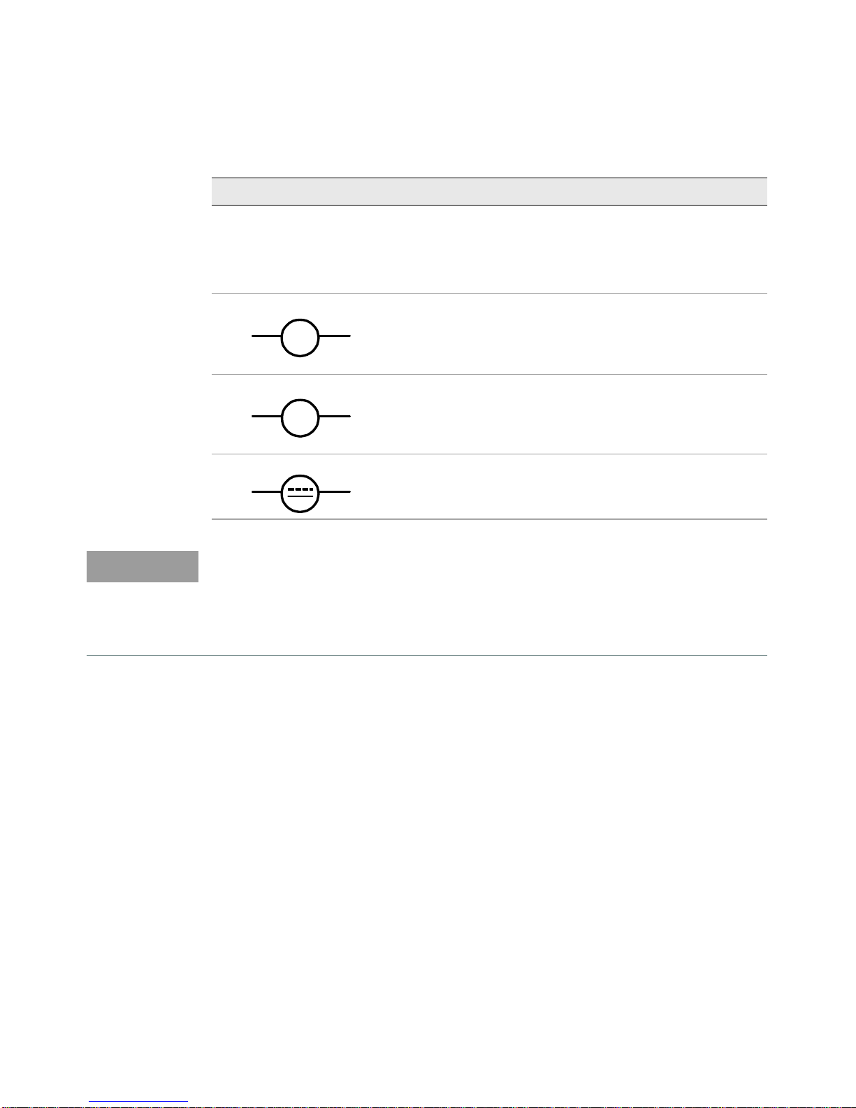
Safety Symbols
The following symbols on the instrument and in the documentation indicate
precautions which must be taken to maintain safe operation of the instrument.
Direct current (DC) Alternating current (AC)
Caution, risk of electric shock
Standby supply. Unit is not completely
connected from AC mains when
switched off
Protective earth (ground) terminal
Caution, risk of danger (refer to this
manual for specific Warning or Caution
information)
Frame or chassis (ground) terminal
Equipment protected throughout by
double insulation or reinforced
insulation
Keysight X8712A IoT Device Battery Life Optimization Solution User’s Guide 3
Page 4

Safety Considerations
Read the information below before using this instrument.
The following general safety precautions must be observed during all phases of
operation, service, and repair of this instrument. Failure to comply with these
precautions or with specific warnings elsewhere in this manual violates safety
standards for design, manufacture, and intended use of the instrument. Keysight
Technologies assumes no liability for the customer’s failure to comply with these
requirements.
General
Do not use
protective features of this product may be impaired if it is used in a manner not
specified in the operation instructions.
this product in any manner
not specified by the manufacturer. The
Before Applying Power
Verify that all safety precautions are taken. Make all connections to the unit before
applying power and select the appropriate power line voltage on the fuse module.
Ground the Instrument
This product is provided with protective earth terminals. To minimize shock
hazard, the instrument must be connected to the ac power mains through a
grounded power cable, with the ground wire firmly connected to an electrical
ground (safety ground) at the power outlet. Any interruption of the protective
(grounding) conductor or disconnection of the protective earth terminal will cause
a potential shock hazard that could result in personal injury.
Do Not Operate in an Explosive Atmosphere
Do not operate the instrument in the presence of flammable gases or fumes.
Do Not Remove the Instrument Cover
Only qualified, service-trained personal who are aware of the hazards involved
should remove instrument covers. Always disconnect the power cable and any
external circuits before removing the instrument cover.
Do Not Modify the Instrument
Keysight X8712A IoT Device Battery Life Optimization Solution User’s Guide 4
Page 5

Do not install substitute parts or peorm any unauthorized modification to the
product. Return the product to a Keysight Sales and Service Office for service and
repair to ensure that safety features are maintained.
In Case of Damage
Instruments that appear damaged or defective should be made inoperative and
secured against unintended operation until they can be repaired by qualified
service personnel.
Keysight X8712A IoT Device Battery Life Optimization Solution User’s Guide 5
Page 6

Environmental Conditions
The X8712A is designed for indoor use and in an area with low condensation. The
table below shows the general environmental requirements for this instrument.
Environmental condition Requirement
Temperature
Humidity
Altitude Up to 2000 m
Pollution degree 2
Operating condition
– 0 °C to 55 °C
Storage condition
– –30 °C to 70 °C
Operating condition
– Up to 80% RH at 40°C (non-condensing)
Storage condition
– Up to 95% RH at 40°C (non-condensing)
Keysight X8712A IoT Device Battery Life Optimization Solution User’s Guide 6
Page 7

Regulatory Information
The X8712A complies with the following safety and Electromagnetic Compatibility
(EMC) compliances:
Safety compliance
– IEC 61010-1:2010 / EN 61010-1:2010
– Canada: CAN/CSA-C22.2 No. 61010-1-12
– USA: ANSI/UL Std.No. 61010-1:2012
EMC compliance
– IEC 61326-1:2012 / EN 64326-1:2013
– Canada: ICES/NMB-001: Issue 4, June 2006
– Australia/New Zealand: AS/NZS CISPR 11:2011
Keysight X8712A IoT Device Battery Life Optimization Solution User’s Guide 7
Page 8

Regulatory Markings
The CE mark is a registered trademark
of the European Community. This CE
mark shows that the product complies
with all the relevant European Legal
Directives.
ISM 1-A indicates that the instrument
is an Industrial Scientific and Medical
Group 1 Class A product (CISPER 11,
Clause 4)
ICES/NMB-001 indicates that this ISM
device complies with the
Canadian ICES-001.
Cet appareil ISM est conforme a la
norme NMB-001 du Canada.
The ETL mark is a registered trademark
of Intetek.
This symbol indicates the time period
during which no hazardous or toxic
substance elements are expected to
leak or deteriorate during normal use.
Forty years is the expected useful life
of the product.
This symbol is a South Korean A EMC
Declaration, with product identification
code R-REM-Kst-GM18498.
This equipment is suitable for
professional use and is for use in
electromagnetic environment outside
of the home.
The CSA mark is a registered
trademark of the Canadian Standards
Association.
The RCM mark is a registered
trademark of the Spectrum
Management Agency of Australia.
This signifies compliance with the
Australia EMC Framework regulations
under the terms of the Radio
Communication Act of 1992.
This instrument complies with the
WEEE Directive (2002/96/EC) marking
requirement. This affixed product label
indicates that you must not discard
this electrical or electronic product in
domestic household waste.
Keysight X8712A IoT Device Battery Life Optimization Solution User’s Guide 8
Page 9

Waste Electrical and Electronic Equipment (WEEE) Directive 2002/
96/EC
This instrument complies with the WEEE Directive (2002/96/EC) marking
requirement. This affixed product label indicates that you must not discard this
electrical or electronic product in domestic household waste.
Product category
With reference to the equipment types in the WEEE directive Annex 1, this
instrument is classified as a “Monitoring and Control Instrument” product.
The affixed product label is as shown below.
Do not dispose in domestic household waste.
To return this unwanted instrument, contact your nearest Keysight Service Center,
or visit http://about.keysight.com/en/companyinfo/environment/takeback.shtml
for more information.
Keysight X8712A IoT Device Battery Life Optimization Solution User’s Guide 9
Page 10

Sales and Technical Support
To contact Keysight for sales and technical support, refer to the support links on
the following Keysight websites:
– www.keysight.com/find/X8712A
(product-specific information and support, software
documentation u
– www.keysight.com/find/assist
(worldwide contact information for repair and service)
pdates)
and
Keysight X8712A IoT Device Battery Life Optimization Solution User’s Guide 10
Page 11

Table of Contents
Safety Symbols . . . . . . . . . . . . . . . . . . . . . . . . . . . . . . . . . . . . . . . . . . . . .3
Safety Considerations . . . . . . . . . . . . . . . . . . . . . . . . . . . . . . . . . . . . . . . .4
Environmental Conditions . . . . . . . . . . . . . . . . . . . . . . . . . . . . . . . . . . . . 6
Regulatory Information . . . . . . . . . . . . . . . . . . . . . . . . . . . . . . . . . . . . . . .7
Safety compliance . . . . . . . . . . . . . . . . . . . . . . . . . . . . . . . . . . . . . . . .7
EMC compliance . . . . . . . . . . . . . . . . . . . . . . . . . . . . . . . . . . . . . . . . .7
Regulatory Markings . . . . . . . . . . . . . . . . . . . . . . . . . . . . . . . . . . . . . . . . . 8
Waste Electrical and Electronic Equipment (WEEE) Directive 2002/96/
EC . . . . . . . . . . . . . . . . . . . . . . . . . . . . . . . . . . . . . . . . . . . . . . . . . . . . . 9
Product category . . . . . . . . . . . . . . . . . . . . . . . . . . . . . . . . . . . . . . . . .9
Sales and Technical Support . . . . . . . . . . . . . . . . . . . . . . . . . . . . . . . . .10
1 Getting Started
To Prepare Instrument for Use . . . . . . . . . . . . . . . . . . . . . . . . . . . . . . . .14
Equipment Requirements . . . . . . . . . . . . . . . . . . . . . . . . . . . . . . . . .14
Software Requirements . . . . . . . . . . . . . . . . . . . . . . . . . . . . . . . . . . .15
System and Installation Requirements . . . . . . . . . . . . . . . . . . . . . . .16
Characteristics . . . . . . . . . . . . . . . . . . . . . . . . . . . . . . . . . . . . . . . . . . 16
Overview . . . . . . . . . . . . . . . . . . . . . . . . . . . . . . . . . . . . . . . . . . . . . . . . .17
N6705C DC Power Analyzer with N6781 SMU Unit . . . . . . . . . . . . .17
N6705C Two-Channel Configuration . . . . . . . . . . . . . . . . . . . . . . . . . . .19
Connect an Over-the-Air DUT in Self Advertising or Test Mode . . .19
Pair an External Companion Device in Signaling Mode . . . . . . . . . .21
N6705C Four-Channel Configuration . . . . . . . . . . . . . . . . . . . . . . . . . .23
N6705C Two-Channel Configuration for Non-RF Events . . . . . . . . . . .25
Software Installation . . . . . . . . . . . . . . . . . . . . . . . . . . . . . . . . . . . . . . . .27
KS833A1A Event-Based Power Analysis Application Installer . . . . .27
License Redemption . . . . . . . . . . . . . . . . . . . . . . . . . . . . . . . . . . . . . . . .28
TAP Deployment System License Certificate . . . . . . . . . . . . . . . . . .28
KS833A1A License Certificate . . . . . . . . . . . . . . . . . . . . . . . . . . . . . .28
Keysight X8712A User’s Guide 11
Page 12

License Installation . . . . . . . . . . . . . . . . . . . . . . . . . . . . . . . . . . . . . . . . . 29
KS833A1A Event-Based Power Analysis Software Settings . . . . . . . . . 30
Run the KS833A1A Event-Based Power Analysis Software . . . . . . . . . 34
2Result Analysis
IoT Device Battery Life Optimization Solution . . . . . . . . . . . . . . . . . . . . 36
KS833A1A Event-Based Power Analysis . . . . . . . . . . . . . . . . . . . . . 36
Section A: Main Chart . . . . . . . . . . . . . . . . . . . . . . . . . . . . . . . . . . . . . . 37
Chart Configuration Settings . . . . . . . . . . . . . . . . . . . . . . . . . . . . . . 38
Section B: Tool Bar . . . . . . . . . . . . . . . . . . . . . . . . . . . . . . . . . . . . . . . . . 41
Section C: Calculation Source . . . . . . . . . . . . . . . . . . . . . . . . . . . . . . . . 43
Calculation Source Settings . . . . . . . . . . . . . . . . . . . . . . . . . . . . . . . 45
Results . . . . . . . . . . . . . . . . . . . . . . . . . . . . . . . . . . . . . . . . . . . . . . . . 47
Section D: Zoom and Analysis Chart . . . . . . . . . . . . . . . . . . . . . . . . . . . 49
General Troubleshooting . . . . . . . . . . . . . . . . . . . . . . . . . . . . . . . . . . . . 51
Offline Mode . . . . . . . . . . . . . . . . . . . . . . . . . . . . . . . . . . . . . . . . . . . 51
Online Mode (Active Connection to N6705C Unit) . . . . . . . . . . . . . . 52
Software Related Error Messages . . . . . . . . . . . . . . . . . . . . . . . . . . . . . 54
Licenses Not Found . . . . . . . . . . . . . . . . . . . . . . . . . . . . . . . . . . . . . . 54
Center Frequency for Channel 2 . . . . . . . . . . . . . . . . . . . . . . . . . . . . 54
Inconsistent Settings between the Instrument and Software . . . . . 55
Corrupted File . . . . . . . . . . . . . . . . . . . . . . . . . . . . . . . . . . . . . . . . . . 55
Channel Under Protection Mode . . . . . . . . . . . . . . . . . . . . . . . . . . . 56
12 Keysight X8712A User’s Guide
Page 13

Keysight X8712A
IoT Device Battery Life Optimization Solution User’s Guide
1 Getting Started
The X8712A IoT Device Battery Life optimization solution that combines a DC
power analyzer, SMU modules, RF event detector and KS833A1A Event-Based
Power Analysis software in one integrated solution, enabling you to:
– Detect design weakness with quick and effortless event-based power
consumption analysis.
The X8712A automatically correlates critical or DC events of your device to
the power consumed to identify the areas that are consuming the most
current.
– Accurately predict the battery life of your IoT device.
The TAP-based monitoring suite calculates how much time the RF or DC event
occupies and how much current it consumes, and also allows you to view the
estimated battery life.
For more information, visit www.keysight.com/find/X8712A.
13
Page 14

To Prepare Instrument for Use
NOTE
3
6
1
5
4
2
7
8
Equipment Requirements
Item Item
1 Keysight N6705C DC Power Analyzer (Rear Panel) 5
2 USB interface connector 6 X8712AD RF Event Detector with 50 Ohm terminator
3 Laptop/PC with USB port ** 7 Device-Under-Test (DUT) **
4 KS833A1A Event-Based Power Analysis software 8 Shield box with antenna **
Refer to N6705C User's Guide for instructions on how to install the N6781A SMU
unit into the N6705 DC Power Analyzer.
14 Keysight X8712A User’s Guide
Keysight N6705C DC Power Analyzer (Front Panel) with
Keysight N6781A Battery Drain Analyzer source
measure unit (SMU) modules.*
Page 15

–Micro USB cable
NOTE
NOTE
–USB Type A/B cable
–Test Lead**
–RF cable*
Getting Started 1
– Your choice of sensor kit such as color, brightness, and
depending to t
– * These accessories are not included in the X8712A IoT Device Battery Life
Op
timization Solution.
– ** You can find Keysight Test Leads here.
– *** You may need to provide additional DC current to power the sensor
he events monitored***
Software Requirements
– Keysight License Manager version 5.3 or above
– Keysight IO Libraries Suite 2018 version
(via USB connection)
Keysight Test Automation Platform (TAP) Deployment System version 8.3.522
–
– Keysight Event-Based Power Analysis software
vibration sensors
kit.
18.1.22713.0 or above
Go to www.keysight.com/find/X8712A to purchase the licenses required for this
X8712A solution.
Keysight X8712A User’s Guide 15
Page 16

System and Installation Requirements
PC operating system
– Windows 7 SP1 (64-bit)
– Windows 10 (64-bit)
Characteristics
For characteristics of this solution, refer to the respective data sheet.
– X8712A IoT Device Battery Life Optimization Solution Data Sheet
http://literature.cdn.keysight.com/litweb/pdf/5992-3085EN.pdf
16 Keysight X8712A User’s Guide
Page 17

Overview
V
I
N6705C DC Power Analyzer with N6781 SMU Unit
Getting Started 1
The X8712A consists of the N6705C DC Power Analyzer, the two-quadrant
N6781A Battery Drain Analyzer source measure unit modules, X8712AD RF Event
Detector and the KS833A1A Event-Based Power Analysis software.
The N6705C DC Power Analyzer can measure DC voltage and current to and from
the device-under-test (DUT). The N6781A is a battery emulator tailored for
powering IoT devices up to 20 W and measuring current drain from nA to A using
patented seamless current ranging technology.
Channel Settings
You can configure the N6705C unit of the X8712A solution based on the settings
below.
Channel Settings
Channel 1
Channel 2
Keysight X8712A User’s Guide 17
Fixed as Battery Emulator
Function: Act as battery of the DUT.
Note: The software will block remaining channels upon selection.
Fixed as RF Power Detector
Function: Capture RF and/or DC events
Connect the X8712AD RF Event Detector to channel 2
Page 18
Channel Settings
V
A
NOTE
You can choose two options from below:
Channel 3 and 4
Voltage meter
Current meter
DC Power Supply
– Voltage meter
– Current meter
– DC Power Supply
Function: Measure voltage
Function: Measure current
Function: Force Voltage to measure Current
Take note of the following:
– Channel 1 should be set as Battery Emulator
– Channel 2 should be set as RF Power Detector.
– Refer to software settings at page 30.
Based on the above mentioned hardware, the following section illustrates
examples of hardware setup depending on your choice of DUT and test
requirement.
– Two-channel Configuration on page 19
– Option 1: Connect an over-the-air DUT with self advertising or in test mode
– Option 2: Pair an external companion device in signaling mode
– Comparison of power levels between Option 1 and 2
– Four-channel Configuration (Channel 1 to 4) on page 23
– Use Contact or Non-Contact sensors with voltage or current behavior
response to synchronize the events
18 Keysight X8712A User’s Guide
Page 19

N6705C Two-Channel Configuration
The two channel configuration is a typical hardware requirement to operate the
Keysight KS833A1A Event-Based Power Analysis software. Below are examples of
hardware setup based on two types of DUT, an over-the-air DUT (below) and
external companion device (page 21).
Connect an Over-the-Air DUT in Self Advertising or Test Mode
The image below illustrates the typical setup to connect an over-the-air DUT.
Getting Started 1
Follow the instructions below to connect the X8712A solution as shown above.
1 Refer to N6705C User's Guide for instructions on how to install the N6781A
SMU unit into the N6705 DC Power Analyzer.
2 Connect a USB Type A/B cable from your PC to the back of the rear panel of
the N6705C.
3 Connect the Micro USB cable from the N6705C DC Power Analyzer to the
X8712AD RF Event Detector.
4 Use the test leads (not included) to connect your DUT to Channel 1 (Battery
Emulator).
Keysight X8712A User’s Guide 19
Page 20

5 There are two RF ports on X8712AD. Connect the RF cable (not included) to
NOTE
V+
V-
S+ S- adapter
for support only
USB A to Micro cable,
5V DC
RF Input
Frequency range: 10MHz - 3GHz
Sensitivity: -40 to 0 dBm
Port 2
Port 1
CAUTION
one of the RF ports and the other end to the back of the shield box. Connect
the 50 Ohm terminator to the port not in use.
– The 2 in 1 power combiner within the X8712AD produces equal RF signal on
Port 1 and Port 2 on the front panel.
– You are recommended to connect the 50 Ohm terminator to the unused port
to avoid open reflection when you use one of the ports to measure RF power.
– The pass through loss between port 1 and 2 is approximately 7 to 8dB.
6 Connect the X8712AD RF Event Detector to Port 2, use V+ and V- 2-wire
configuration to receive analog response at rear banana port as shown below.
The output will range from 0 to 2V.
7 The X8712AD RF Event Detector has a micro male adapter at the front panel
as well, that requires 5V of DC to operate the event detector.
Set Channel 2 in Voltage meter (VMM) mode before you turn on the output,
to prevent generating DC output to the X8712AD RF Event Detector.
You have completed the hardware setup based on this example.
Go to Software Installation section to install the required software to operate the
X8712A IoT Device Battery Life Optimization Solution.
20 Keysight X8712A User’s Guide
Page 21

Pair an External Companion Device in Signaling Mode
NOTE
The image below illustrates the typical setup to pair an external companion device
in signaling mode.
Getting Started 1
Follow the instructions below to connect the X8712A solution as shown above.
1 Follow the instructions from step 1 to step 7 in the Connect an Over-the-Air
DUT in Self Advertising or Test Mode section.
2 Connect your companion device to the other front end connector of the
X8712AD RF Event Detector.
For sensitivity measurement, take note that the pass through loss between port
1 and 2 of the X8712AD is approximately 7 to 8dB.
You have completed the hardware setup based on this example.
Go to Software Installation section to install the required software to operate the
X8712A IoT Device Battery Life Optimization Solution.
Keysight X8712A User’s Guide 21
Page 22

Based on the two setups mentioned in page 19 and page 21, the diagram below
Pairing Device
Downlink
DUT
Uplink
X8712A RF Power kit
Shield Box
Refer to Note.
NOTE
Time
RF (dBm)
Pairing Device
DUT
Upper Threshold
Lower Threshold
combines the setups and illustrates the difference in RF energy transmitted by the
pairing device and DUT.
The N6781A SMU unit has a limit of 13 dBm. It is recommended to add a fixed
attenuator when you require an input power of more than +10 dBm to avoid
overstress.
The 1x2 Splitter within the X8712AD responds and produces different power levels
in time domain compared to the upper and lower threshold as illustrated in the
chart below. You can see this chart in the Zoom Chart on page 49.
22 Keysight X8712A User’s Guide
Page 23

N6705C Four-Channel Configuration
This setup is recommended for multi-event synchronization testing for both
signaling and normal operation. Normal operation is defined as the operation
upon successful connection.
This 4 channel configuration requires the following setup:
– Channel 1: Connect DUT
– Channel 2: Connect X8712AD RF Event Detector
– Channel 3 and 4: Connect sensors with voltage or current behavior
response to synchronize the events
Getting Started 1
The setup below uses two additional channels:
– Channel 3 as Voltage meter.
– Channel 4 as Current meter.
Choosing DC Power Supply settings requires the correct voltage to measure
current.
Keysight X8712A User’s Guide 23
Page 24

Connect the respective Contact or Non-Contact sensors to the respective
channels set on page 17:
– Voltage meter
– Current meter
– DC Power Supply
1 Follow the instructions from step 1 to step 7 of the Connect an Over-the-Air
DUT in Self Advertising or Test Mode section).
2 Connect your voltage-based sensor to Channel 3 using V+ and V- accordingly.
Do the same to connect the current-based sensor to Channel 4.
You have completed the hardware setup based on this example.
Go to the Software Installation section to install the required software to operate
the X8712A IoT Device Battery Life Optimization Solution.
24 Keysight X8712A User’s Guide
Page 25

Getting Started 1
N6705C Two-Channel Configuration for Non-RF Events
The following is a typical setup for non-RF events. Use the following software
settings for two channels:
– Channel 1: Battery emulator for DUT
– Channel 3 or 4: Voltage meter or Current meter, according to your choice
of sensors
When Channel 3 or 4 is connected to the DUT, the software will use either channel
as synchronous events to calculate current consumption since Channel 2 is fixed
as RF Event Detector.
Follow the instructions below to connect the X8712A solution as shown above.
1 Refer to N6705C User's Guide for instructions on how to install the N6781A
SMU unit into the N6705 DC Power Analyzer.
2 Connect the Micro USB cable from the N6705C DC Power Analyzer to the
X8712AD RF Event Detector.
3 Use the test leads (not included) to connect your DUT to Channel 1 (Battery
Emulator).
Keysight X8712A User’s Guide 25
Page 26

4 Connect the RF cable from the X8712AD RF Event Detector to the back of the
shield box.
5 Connect your voltage-based sensor to Channel 3 or 4 using V+ and V-
accordingly.
You have completed the hardware setup based on this example.
Go to Software Installation section to install the required software to operate the
X8712A IoT Device Battery Life Optimization Solution.
26 Keysight X8712A User’s Guide
Page 27

Software Installation
The following installation requires your PC to be connected to the Internet.
KS833A1A Event-Based Power Analysis Application Installer
This installer will search for the necessary pre-requisites in your PC and it will
send alerts when the PC does not have certain software listed in Software
Requirements section.
1 Go to www.keysight.com/find/X8712A and look for the KS833A1A
Event-Based Power Analysis software in the 'Options and Accessories Related Products and Solutions' tab to download the installer.
2Run the installer and follow the installation instructions accordingly.
3 Click Finish to exit the InstallShield Wizard.
Upon successful installation, the software will be listed in the Start menu.
Otherwise, find the application in the C:\Program Files\Keysight\EBPA directory.
Proceed to redeem the license(s) required to operate the software in the next
section.
Getting Started 1
Keysight X8712A User’s Guide 27
Page 28

License Redemption
TAP Deployment System License Certificate
1 Refer to the email or printed Keysight License Entitlement Certificate for
instructions on how to redeem your license.
2 Follow the instructions on the Keysight Software License Entitlement
Certificate to redeem your licenses and obtain the license files. You will need to
go to Keysight Software Manager website www.keysight.com/find/
softwaremanager.
KS833A1A License Certificate
1 Refer to the email or printed Keysight License Entitlement Certificate for
instructions on how to redeem your license.
2 Follow the instructions on the Keysight Software License Entitlement
Certificate to redeem your licenses and obtain the license files. You will need to
go to Keysight Software Manager website www.keysight.com/find/
softwaremanager.
28 Keysight X8712A User’s Guide
Page 29

License Installation
1 You will receive an email for the license file(s). Copy the attachments with the
.lic extension to your PC.
2 Launch Keysight License Manager.
3 Perform the following steps with reference to the image below.
a Click the tools icon (1) followed by Install License File (2).
b Locate the local copy of the License file (.lic) and click Open.
c Successful license installation will be listed as below.
Getting Started 1
4 Repeat step 1 to add new licenses.
You have completed the hardware setup and software installation for the X8712A
solution. Go to the next section to learn the functionalities of the KS833A1A
Event-Based Power Analysis Software Settings.
Keysight X8712A User’s Guide 29
Page 30

KS833A1A Event-Based Power Analysis Software Settings
Customize the following software settings according to your test requirement.
Settings Description
Setup
Display status of the instrument
next to the Acquire button.
The status will change
depending on the connection of
the instrument:
– Online mode will display the
VISA address.
– Offline mode will display the
name of the loaded file.
Zones
Automatically divides the
acquired Channel 1 waveform
(from maximum to minimum)
into equal parts depending on
the number of zones selected.
Connect or Disconnect
Choose the respective VISA address and click Connect or Disconnect
button. Upon successful connection, it will display a status such as
“Connected to N6705C//<VISA Address>” next to the Acquire button.
Load Last Data:
Click this button to load last settings and data.
Abort
Click to stop acquiring measurement results and return to edit mode.
Acquire
Click to acquire instrument data from the connected instrument.
Show Zones
Show numbered lines from 1 to 20 that equally divides the main chart
according to the number selected in the drop-down list. Default: 10
30 Keysight X8712A User’s Guide
Page 31

Settings Description
Getting Started 1
Avg Channel 1
Sample & Duration
Sets the following criteria to
initialize and set up the software
to obtain real-time results.
This waveform is digitized from Channel 1 to define the current event
mentioned in page 44. This option is available in Show Legend once
the software acquired waveform from Channel 1 according to the zone
numbers selected.
Click Acquire once you change the zone number to reflect the
changes on the Avg Channel 1 waveform. Click Analyze will not
change the Avg channel 1 waveform.
Sample Size
Define the number of points in a measurement where the minimum
point is 1. The range is dependent on the number of channels below:
– One channel: up to 512K points.
– Two channels: up to 256K points.
– Three channels: up to 128K points.
– Four channels: up to 64K points
where K equals to 1024.
Time Interval (s)
Define the time period between samples, where the maximum is 0.1
seconds. The minimum time interval is dependent on the number of
channels below:
– One channel: 5.12 microseconds.
– One or two channels: 10.24 microseconds
– Three or four channels: 20.48 microseconds
Time Span (s)
Calculated by the software with a given Sample Size and Time Interval.
Keysight X8712A User’s Guide 31
Page 32

Settings Description
Channel
Software settings for each
channel
Settings for Channel 1 and 2 modules are predetermined according to
Channel Settings:
Channel 1: Battery Emulator
Channel 2: Power Detector
Select any of the following for Channel 3 and 4:
– Current meter
– Voltage meter
– 2-Q Power Supply
Selecting the 2-Q Power Supply module for Channel 3 or 4 will
require user to set a voltage in order to measure current.
Note: Current measured could be a positive or negative value.
Deselect the Enable box of the respective channels that are not in use
and consequently, it will disable the settings in Section C: Calculation
Source.
Note: Channel 1 Battery Emulator sets constant voltage and measure
current. The current limit functions to protect the DUT and act as
measurement range. When the limit is set to less than 0.1A, the
X8712AD will use 10 uA range to obtain sub uA accuracy. The
maximum current limit is 3A, according to N6781A specifications.
32 Keysight X8712A User’s Guide
Page 33

Settings Description
Getting Started 1
Trigger
Set triggering point to start or
stop tabulating the results.
Two trigger modes available.
Single Mode:
Send immediate trigger to the
measurement system.
Triggered Mode:
Only start capturing waveform
when criteria are met.
Settings for Single Mode
– Status: To trigger instrument remotely with/without reset.
– Reset: Reset the N6705C default settings and data according to
software settings. The software will reset the settings for Power
supply and may turn OFF/ON the channel. You will see the
changes at front panel.
– Without Reset: Keep existing instrument settings. The software
will promote the message check box when the hardware and
software configuration settings are different. The software will
take control of the settings.
– Delay: Check this box to enable or disable delay time between
pressing the Acquire button and the actual start time of the
measurement.
– Delay(s): Enter the desired delay time in seconds. Default: 0.
– Center Frequency (MHz): Range from 100 to 2900 MHz.
Default: 2402 MHz.
Triggered Mode will enable the following additional settings:
– Source: The software will save last trigger settings across all 4
channels when you have N6781A. Select 1 channel at a time.
–Slope:
– Rising: Increasing waveform.
– Falling: Decreasing waveform.
– Level: Set the threshold level (shown in green below).
Keysight X8712A User’s Guide 33
– Time Variable (s): Set the time out.
– Time Out (s): Calculated by the software based on a given Time
Variable and Time Span.
– Offset: Defines the offset in a data sweep when the measurement is
triggered. Value should less than half of the entire time span.
Default: 0.01 seconds.
Page 34

Run the KS833A1A Event-Based Power Analysis Software
NOTE
At this point, you will need to verify the module settings in the software to be the
same as your hardware connection before you turn on your N6705C unit.
1 Turn on your device-under-test (DUT) and place it in the shield box. Close the
shield box.
2 Click Connect to verify your hardware connections.
3 Click Acquire to begin capturing the waveforms. The Acquire button will
change to ‘Abort’ during the measurement.
During the measurement, the ‘Acquire’ button will change to ‘Abort’ button and
disable the settings control listed on page 30. Upon successful data acquisition,
click ‘Edit’ to enable settings control.
An example of a successful results as shown below. Capabilities of the software is
covered in Chapter 2, "Result Analysis".
34 Keysight X8712A User’s Guide
Page 35

Keysight X8712A
IoT Device Battery Life Optimization Solution User’s Guide
2 Result Analysis
The KS833A1A Event-Based Power Analysis software helps you analyze the data
acquired with the N6705C and N6781A by providing a visual representation of the
RF signals of your IoT device in dB or non-RF signals in DC voltage
measurements, and maps these signals to the current measurement in a single
graph.
Its capabilities include:
– Automated correlation between RF/DC signals to power consumption in a
single display
– Single shot waveform capture
– Individual event's post data analysis
– Current consumption in percentage
– Occupied time in percentage
– Battery life estimation
– Triggering function by each channel
– In-depth current analysis by zones/segments
– CCDF statistical analysis
– Save and recall settings which include raw data and instrument settings
– Export raw data and measurement results in .csv format for post analysis
35
Page 36

2 Result Analysis
C
A
D
B
IoT Device Battery Life Optimization Solution
KS833A1A Event-Based Power Analysis
From Chapter 1, "Getting Started", you will use the graph below as an example to
explore the capabilities offered in the Keysight KS833A1A Event-Based Power
Analysis software.
The descriptions and functions of each section will be segregated according to
the sections below.
From this section onwards, refer to the following sections as:
– Section A: Main Chart
–Section B: Tool Bar
– Section C: Calculation Source
– Section D: Zoom and Analysis Chart
36 Keysight X8712A User’s Guide
Page 37

Section A: Main Chart
A
Result Analysis 2
The following general settings fall under main tab below ‘File’ and ‘Help File’ tab.
Settings Description
Open Open saved settings in .analysis file format.
Save Settings
Save Settings AsSave instrument settings and raw data in .analysis file with a naming of your choice.
Export Export data in .csv file with the settings and results from:
Help File Open the Help File embedded within the application.
Save instrument settings and raw data in default.analysis file.
You can only use the KS833A1A Event-Based Power Analysis software to open this file.
– Analysis mode
–XY mode
– Zoom trace data from selected channel
You can open these .csv files using Microsoft Excel.
Keysight X8712A User’s Guide 37
Page 38

2 Result Analysis
Chart Configuration Settings
The configurations settings for the main chart can be found towards the left of the
main chart. Click to expand the following settings.
Chart Settings Description
Edit the display settings of the
main chart.
Title
Name the title of your graph.
Show Legend
Show the color of each trace line and click the check box to enable or
disable the trace line accordingly.
Data Series Tooltip
Check this box to display respective X and Y data for each point when
you point the main chart with a cursor.
Shift Data Series
Separate the trace to avoid overlapping Y axes as shown below.
38 Keysight X8712A User’s Guide
Page 39

X-Axis Settings Description
The X-axis is for Time Title
Default: Time
Label Rotation
Rotates the X-axes values according to the degrees set. Default: 0
Data Label Unit
– Unit: Default: <blank>
– Show in title: Select to display unit on X-axis title
– Decimal Points: 2
– Use Engineering Prefix: Convert existing values to SI prefixes
Grid lines
– Major: Automatically divides X-axis into major sections.
– Minor: Automatically divides X-axis into minor sections.
Result Analysis 2
Y-Axis Settings Description
Select to configure settings for
the Ampere, dBm or Volt line
graph.
Label Rotation
Rotates the Y-axes values according to the degrees set. Default: 0
Data Label Unit
– Unit: Default: <blank>
– Show in title: Select to display unit on X-axis title
– Decimal Points: 0
– Use Engineering Prefix: Convert existing values to SI prefixes
Gridlines
– Major: Automatically divides Y-axis into major sections.
– Minor: Automatically divides Y-axis into minor sections.
Keysight X8712A User’s Guide 39
Page 40

2 Result Analysis
Series Settings Description
A selection of Channel 1, 2, 3
and 4 to set trace line
parameters.
Series Name
Default: Channel 1
Line Thickness
Default: 1
Here are several features that are available in the main chart of the KS833A1A
Event-Based Power Analysis Software.
Features Steps
Zoom In
Auto scale Y-axis Point the cursor to Y-axis and double click to auto scale.
Auto scale Main
Chart
Shift X-axis Click at trace line to shift the chart.
Drag your cursor across the chart until you see a square covering the desired area.
Release to zoom in on the chart.
Point the cursor at the main chart and double click to auto scale the main chart.
40 Keysight X8712A User’s Guide
Page 41

Section B: Tool Bar
B
Result Analysis 2
The tool bar consists of the following settings:
Settings Description
Mode – Analysis: Display Section C: Calculation Source settings and results.
– XY: Display the respective X and Y values in a selected series, at one
particular point.
View – Table: Select to view results in table form in Section C: Calculation Source
– Chart: Select to view results in chart form in Section D: Zoom and Analysis
Chart
Keysight X8712A User’s Guide 41
Page 42

2 Result Analysis
Settings Description
X Label
Turns on the time label of the two line markers in the main chart. Drag the line
markers (shown below) to contain the desired area for analysis.
The time label will update once you drag the line marker and the calculation
should be done once you press the Analyze button.
Analyze
Click this button to analyze the area between the two line markers in the main
chart. Move the red vertical line manually and click Analyze.
The respective values in Section C: Calculation Source and Section D: Zoom
and Analysis Chart will be change according to the areas marked between the
line markers.
42 Keysight X8712A User’s Guide
Page 43

Section C: Calculation Source
C
a
b
This section and the next Section D: Zoom and Analysis Chart are calculated and
illustrated based on the area set between the two line markers in the main chart.
See page 37 to learn more about the main chart’s functionalities.
Result Analysis 2
Click the drop down list and deselect Chart to view the complete table below.
Keysight X8712A User’s Guide 43
Page 44

2 Result Analysis
NOTE
There are two sections as shown in the image above:
These channels will be grayed out when it is deselected in software settings.
Based on the image above, the Calculation table contains several columns in
colors that corresponds to the front panel of the N6705C. The table below
contains the details of each column with its priority are arranged from highest to
lowest (top to bottom).
Name Label Color Definition
a Physical event
Channel 2 to 4 are known as Physical events, where these events are
optional depending on the channel selected. These channel remain in gray
when unselected in software settings.
b Current event
Other events, derived from the current waveform (Channel 1) using Zone
are always valid when the program is running. The region is defined by the
upper or lower zones of Avg Channel 1 data described on page 31.
Ch 2 Pwr Det DUT TX
Ch 2 Pwr Det Pair TX
Ch 3 - XXX Event 1 Blue
Ch 4 - XXX Event 2 Purple
Avg Ch1 - Battery Region 1 Pink
Avg Ch1 - Battery Region 2
Avg Ch1 - Battery Region 3 Brown Same as Region 1 with the lowest priority
Light
Green
Dark
Green
Dark
Yellow
Synchronous comes from X8712AD, assign as DUT’s TX
events with the highest priority.
Synchronous comes from X8712AD, assign as Pairing TX
or DUT RX events with second highest priority.
XXX could be in VMM, AMM or 2QPS mode from
selection, synchronous from Channel 3. Default: VMM
XXX could be in VMM, AMM or 2QPS mode from
selection, synchronous from Channel 4. Default: VMM
Zones are evenly distributed from minimum to maximum
of average channel 1 based on number of Zones set.
Same as Region 1 with a lower priority
When there are two events in the same zone, the software will prioritize the
events listed towards the left of the Calculation Source table. The software will
not take in consideration of the disabled channels in page 32 as part of the
Results.
44 Keysight X8712A User’s Guide
Page 45

Calculation Source Settings
The description for each settings in the Calculation Source are as below.
Settings Description
Result Analysis 2
Battery Capacity (Ah)
Label
Key in the capacity of the battery tested in ampere-hours. The program will
calculate the battery life estimation based on the area between the two line
markers in the main chart.
Default: 0.2 A (based on the capacity of a CR2302 coin cell)
Note: Key in the correct battery capacity to obtain accurate results for Total
Charge and Battery Life.
The waveform is segregated according to different event based on the upper
and lower threshold. Each event is categorized according to the label color.
Unit This setting will depend on the selected module as shown below
Keysight X8712A User’s Guide 45
You can also change the label of the events directly on the table. Click Analyze
after making the changes for it to take effect immediately.
– Power Detector: dBm
–Voltage Meter: Volt
– Current Meter or 2-Q Power Supply: Ampere
Page 46

2 Result Analysis
Settings Description
Upper Threshold and
Lower Threshold
The range for the respective unit are as below:
– dBm: -45 to +10
– Volt: -20 to +20
– Ampere: -3 to +3
– Power Supply: -3 to +3 Ampere
Note: The upper threshold cannot be lower than the lower threshold.
Upper Threshold and
Lower Threshold
(Region 1 and 2)
Select the lower and upper threshold in terms of Zones number from the
drop-down list that contain the desired area for analysis.
Note: The upper threshold cannot be lower than the lower threshold.
Other Remaining profiles
46 Keysight X8712A User’s Guide
Page 47

Results
Result Analysis 2
The following results are calculated based on the area set between the two line
markers in the main chart. See page 37 to learn more about the main chart’s
functionalities.
You can view several of these results in the four charts available in Section D:
Zoom and Analysis Chart.
Results Description
Occupied Time The time taken for each occupied event under the cycle time.
Sorts synchronous physical or current events from page 44 within cycle time.
Charge by Event
Max Current Maximum current recorded between the two line markers.
Avg Current
Cycle Time The time taken between the two line markers set in the main chart.
Synchronous charge is defined as the mapping of the same time position
current in Channel 1 and integrating them as charge by event. The sum of all
charges by events will equal to Total Charge.
Charge by Event = Synchronous charge by events (Ah) / Total Charge (Ah)
within cycle time * 100%
Average current recorded between the two line markers.
Avg current = Total Charge (Ah) / Cycle time (h).
Keysight X8712A User’s Guide 47
Page 48

2 Result Analysis
Results Description
Total Charge Current integration based on cycle time to measure charge capacity in Ampere
per hour.
Total Charge (Ah) = sum of all Channel 1 current data within cycle time * time
interval / 3600 seconds
Battery Life
Measure battery life in hours based on the amount of Charge by Event cycle
time and battery capacity set.
Battery Life = Battery Capacity (Ah) / Total Charge (Ah) * Cycle time (h).
48 Keysight X8712A User’s Guide
Page 49

Section D: Zoom and Analysis Chart
D
Result Analysis 2
Click the drop down list and deselect Table to view the complete charts as shown
below. You can deselect the check box next to the name of the four charts to
disable the view of a chart.
Keysight X8712A User’s Guide 49
Page 50

2 Result Analysis
The four available charts are illustrated according to the calculations made based
on the area set between the two line markers in the main chart. You can view
these results in table form shown in Section C: Calculation Source.
Charts Description
Zoom
Current Consumption
CCDF
(Complementary
Cumulative Distribution
Function)
To view the detailed region between the two line markers and categorize
the waveform according to events based on upper and lower threshold.
Amount of current consumed according to the different events illustrated
in a bar chart.
Graph of time taken when a signal is at or above a given power level. A plot
of relative power levels versus probability to explain peak-to-average
ratios. You can maneuver the respective X and Y value markers.
Y axis: Time in percentage
X axis: Current in Log scale
In the example below, the line marker will display the respective X and Y
values being X = 6 m and Y=2. This result is interpreted as 2% of the
accumulated time domain current will be higher than 6 mA.
Occupied Time
50 Keysight X8712A User’s Guide
Calculate occupied time in percentage and illustrate in a pie chart
according to the color of each label.
Page 51

General Troubleshooting
Click “Load L ast
Data” button to
display initial
data.
Can see the
waveform?
End
YES
YES
YES
YES
NO
NO
NO
— Change the win dows scr een resolution
to 1366 x 768 (recommended) or above.
— Re-launch the progra m.
— Check the program is installed.
— Install the 64-bit version for Windows
OS.
— Re-install the program.
— Ver ify t he val idit y of KS833A1A an d
KS8000A licenses in KLS (Keysight
License Service).
— Purchase an d install license for
X8712A.
— When program crash during launch,
remove the three files below in the
C:\Prog ram Fil es\Keysi ght\EBPA
directory.
− Default.analysis
− DefaultOri.json
− DefaultZoom.json
— Re-launch the p rogram.
NO
Launch Keysight EventBased Power Analysis
software.
“Load Last
Data” button
available?
Can launch
software?
Result Analysis 2
Offline Mode
Keysight X8712A User’s Guide 51
Page 52

2 Result Analysis
Conn ect to N6705C
successfully?
Can enable the
channels?
Can set the
voltage or current?
Can get wavef orm
after click
“Acquire”?
YES
YES
YES
YES
NO
NO
NO
NO
— Chec k if N6705C mainf rame has
prote ction in formation or war ning
messages such as OSC/OCP/ CL+/
VL+/ OVP. Remove the protection
before test.
— Chec k N6705C Setti ngs > Protec tion >
Output > CV or CC.
— Verify if there is any error message in
th e dis play of N6705C front pan el.
— Refer to N6705C Service Guide for
hardware troubleshooting.
— Verify the module set in Channel 1 is
Battery Emulator and Channel 2 is
Power Detector.
— Chec k N6705C s ystem info rmation.
— USB device should be auto recognized
by PC under hot plug. Open Keysight IO
Library suite version and observe the
format of the VISA address as below:
USB0::xxxxx::xxxxx::MYxxxx::0::INSTR.
— Verify VISA address and model number
of instrument.
— Refer to N6705C Service Guide when
VISA address is not populated in
Keysight IO library software.
B
Tur n on th e N6705C an d c onnec t to
PC using a USB cable. Launch
Keysight Power Event Monitor
software.
Online Mode (Active Connection to N6705C Unit)
52 Keysight X8712A User’s Guide
Page 53

Can “Acquire”
wavefor m Under
“Trigger”mode?
Can program
obtain correct RF
waveform?
Can program
obtai n corre ct
voltag e and
current waveform?
Is data updated in
the program?
YES
YES
YES
YES
NO
NO
NO
NO
— Check the progress spinner at top left
corner is still running and N6705C
appear “IO” occasionally.
— If the program is sti ll runn ing, either
wait or close t he prog ram.
— Ensure that sensor connected to the
correct channel according to type of
signal.
— Change module to power supply mode
to ensure that recorded signals
corresponded to the event.
— Use a different sensor.
— Ensure that the X8712AD RF event
det ect or is c onne cted to N6705C via
USB. Observe the LED and the red
LED is ON.
— Verify if the RF signal is valid with a
value h igher than -40 dBm.
— Change trigger settings, such as
trigger level and set the offset to
negative (before event start).
— Use N6705C’s front panel Scope View
to check the waveform signal level.
— Change to other trigger event or use
“Single” mode instead of Trigger
mode.
END
B
Result Analysis 2
For troubleshooting procedures related to the N6705 and N6781A, refer to the
following Service Guides: N6705 Service Guide and N6781A Service Guide.
Keysight X8712A User’s Guide 53
Page 54

2 Result Analysis
Software Related Error Messages
Licenses Not Found
You will see the pop-up window when the Keysight KS833A1A Event-Based
Power Analysis software is unable to detect the licenses required within the target
PC.
Here’s a few tips that you can try:
– Verify the validity of the KS833A1A and KS8000A licenses in KLS (Keysight
License Service).
– Purchase KS833A1A and KS8000A licenses at www.keysight.com/find/
X8712A.
Center Frequency for Channel 2
You will see the pop-up below when the range of center frequency for Channel 2
Power Detector is set lower than 100 MHz or higher than 2900MHz.
Here’s a few tips that you can try:
– Set the center frequency to be within the range mentioned in the message.
54 Keysight X8712A User’s Guide
Page 55

Result Analysis 2
Inconsistent Settings between the Instrument and Software
The software will scan through instrument and software settings as the software is
acquiring data from the instrument. Inconsistent settings between the hardware
and software will show the pop-up below.
– Match your instrument and software settings. Otherwise, the software will set
the instrument according to your software settings.
Corrupted File
Here’s a few tips that you can try:
– Remove the three files below in the C:\Program Files\Keysight\EBPA directory:
a Default.analysis
b DefaultOri.json
c DefaultZoom.json
– Launch the program again.
Keysight X8712A User’s Guide 55
Page 56

2 Result Analysis
Channel Under Protection Mode
Protection Mode occurs when an over-voltage, over-temperature, and
over-current inhibit signal or power-fail condition. For some models, protection
mode can detect a power-limit condition.
Here’s a few tips that you can try:
– Turn off the channels that are not in use.
56 Keysight X8712A User’s Guide
Page 57

Distributed by:
dataTec ▪ Ferdinand-Lassalle-Str. 52 ▪ 72770 Reutlingen ▪ Tel. 07121 / 51 50 50 ▪ Fax 07121 / 51 50 10 ▪ info@datatec.de ▪ www.datatec.de
This information is subject to change
without notice. Always refer to the
English version at the Keysight
website for the latest revision.
© Keysight Technologies 2018
Edition 1, August 2018
Printed in Malaysia
*X8712-90001*
X8712-90001
www.keysight.com
 Loading...