

Page 1

Keysight U1273A/U1273AX
Handheld Digital Multimeter
User’s Guide
Page 2

Page 3

Page 4

Notices
CAUTION
WARNING
Copyright Notice
© Keysight Technologies 2012-2017
No part of this manual may be repro-
duced in any form or by any means
(including electronic storage and
retrieval or translation into a foreign
language) without prior agreement and
written consent from Keysight Technologies as governed by United States and
international copyright laws.
Manual Part Number
U1273-90017
Edition
Edition 9, April 1, 2017
Printed in:
Printed in Malaysia
Published by:
Keysight Technologies
Bayan Lepas Free Industrial Zone,
11900 Penang, Malaysia
Technology Licenses
The hardware and/or software
described in this document are furnished under a license and may be
used or copied only in accordance with
the terms of such license.
Declaration of Conformity
Declarations of Conformity for this
product and for other Keysight products may be downloaded from the
Web. Go to http://www.keysight.com/
go/conformity. You can then search by
product number to find the latest Declaration of Conformity.
U.S. Government Rights
The Software is “commercial computer
software,” as defined by Federal Acquisition Regulation (“FAR”) 2.101. Pursuant to FAR 12.212 and 27.405-3 and
Department of Defense FAR Supplement (“DFARS”) 227.7202, the U.S.
government acquires commercial computer software under the same terms
by which the software is customarily
provided to the public. Accordingly,
Keysight provides the Software to U.S.
government customers under its standard commercial license, which is
embodied in its End User License
Agreement (EULA), a copy of which can
be found at http://www.keysight.com/
find/sweula. The license set forth in the
EULA represents the exclusive authority
by which the U.S. government may use,
modify, distribute, or disclose the Software. The EULA and the license set
forth therein, does not require or permit, among other things, that Keysight:
(1) Furnish technical information
related to commercial computer software or commercial computer software
documentation that is not customarily
provided to the public; or (2) Relinquish
to, or otherwise provide, the government rights in excess of these rights
customarily provided to the public to
use, mod ify, reproduce, release, perform, display, or disclose commercial
computer software or commercial computer software documentation. No
additional government requirements
beyond those set forth in the EULA
shall apply, except to the extent that
those terms, rights, or licenses are
explicitly required from all providers of
commercial computer software pursuant to the FAR and the DFARS and are
set forth specifically in writing elsewhere in the EULA. Keysight shall be
under no obligation to update, revise or
otherwise modify the Software. With
respect to any technical data as
defined by FAR 2.101, pursuant to FAR
12.211 and 27.404.2 and DFARS
227.7102, the U.S. government
acquires no greater than Limited Rights
as defined in FAR 27.401 or DFAR
227.7103-5 (c), as applicable in any
technical data.
Warranty
THE MATERIAL CONTAINED IN THIS
DOCUMENT IS PROVIDED “AS IS,”
AND IS SUBJECT TO BEING
CHANGED, WITHOUT NOTICE, IN
FUTURE EDITIONS. FURTHER, TO THE
MAXIMUM EXTENT PERMITTED BY
APPLICABLE LAW, KEYSIGHT DISCLAIMS ALL WARRANTIES, EITHER
EXPRESS OR IMPLIED, WITH REGARD
TO THIS MANUAL AND ANY INFORMATION CONTAINED HEREIN, INCLUDING BUT NOT LIMITED TO THE
IMPLIED WARRANTIES OF MERCHANTABILITY AND FITNESS FOR A
PARTICULAR PURPOSE. KEYSIGHT
SHALL NOT BE LIABLE FOR ERRORS
OR FOR INCIDENTAL OR CONSEQUENTIAL DAMAGES IN CONNECTION
WITH THE FURNISHING, USE, OR
PERFORMANCE OF THIS DOCUMENT
OR OF ANY INFORMATION CONTAINED HEREIN. SHOULD KEYSIGHT
AND THE USER HAVE A SEPARATE
WRITTEN AGREEMENT WITH WARRANTY TERMS COVERING THE MATERIAL IN THIS DOCUMENT THAT
CONFLICT WITH THESE TERMS, THE
WARRANTY TERMS IN THE SEPARATE
AGREEMENT SHALL CONTROL.
Safety Information
A CAUTION notice denotes a hazard. It
calls attention to an operating procedure, practice, or the like that, if not
correctly performed or adhered to,
could result in damage to the product
or loss of important data. Do not proceed beyond a CAUTION notice until
the indicated conditions are fully
understood and met.
A WARNING notice denotes a hazard. It
calls attention to an operating procedure, practice, or the like that, if not
correctly performed or adhered to,
could result in personal injury or death.
Do not proceed beyond a WARNING
notice until the indicated conditions are
fully understood and met.
4 Keysight U1273A/U1273AX User’s Guide
Page 5

Safety Symbols
CAT III
1000 V
CAT IV
600 V
The following symbols on the instrument and in the documentation indicate
precautions which must be taken to maintain safe operation of the instrument.
Direct current (DC) Caution, risk of electric shock
Alternating current (AC)
Both direct and alternating current Category III 1000 V overvoltage protection
Earth (ground) terminal Category IV 600 V overvoltage protection
Equipment protected throughout by
double insulation or reinforced
insulation
Caution, risk of danger (refer to this manual
for specific Warning or Caution information)
Caution, risk of hazardous voltage (icon
appears on the instrument screen)
Keysight U1273A/U1273AX User’s Guide 5
Page 6

Safety Considerations
CAUTION
WARNING
Read the information below before using this multimeter. The descriptions and
instructions in this manual apply to the Keysight U1273A/U1273AX
Handheld Digital Multimeter (hereafter referred to as the multimeter).
– Disconnect circuit power and discharge all high-voltage capacitors
before testing resistance, continuity, diodes, or capacitance.
– Use the proper terminals, function, and range for your measurements.
– This device is for use at altitudes of up to 3,000 m.
– Never measure voltage when current measurement is selected.
– Always use the specified battery type. The power for the multimeter is
supplied with four AAA 1.5 V batteries. Observe the correct polarity
markings before you insert the batteries to ensure proper insertion of the
batteries in the multimeter.
– You are advised to use low leakage batteries when changing to new
batteries. Please remember to remove the batteries when the multimeter
is not in use for a long period of time. Warning on the risk of battery
leakage.
– Do not exceed any of the measurement limits defined in the specifications
to avoid instrument damage and the risk of electric shock.
– Do not use the multimeter if it is damaged. Before you use the
multimeter, inspect the case. Look for cracks or missing plastic. Pay
particular attention to the insulation surrounding the connectors.
– Inspect the test leads for damaged insulation or exposed metal. Check
the test leads for continuity. Replace damaged test leads before you use
the multimeter.
– Do not operate the multimeter around explosive gas, vapor, or wet
environments.
– Do not apply more than the rated voltage (as marked on the mul timeter)
between terminals, or between terminal and earth ground.
6 Keysight U1273A/U1273AX User’s Guide
Page 7

WARNING
– Never use the multimeter in wet conditions or when there is water on the
surface. If the multimeter is wet, ensure that the multimeter is dried only
by trained personnel.
– Before use, verify the multimeter's operation by measuring a known
voltage.
– When measuring current, turn off the circuit power before connecting the
multimeter in the circuit. Remember to place the multimeter in series
with the circuit.
– When servicing the multimeter, use only the specified replacement parts.
– Use caution when working above 60 V
DC, 30 VAC RMS, or 42.4 V peak.
Such voltages pose a shock hazard.
– Be aware of the presence of hazardous AC voltage before using the Low
Pass Filter (LPF) function for AC voltage measurement. Voltages
measured are usually greater than what is indicated on the multimeter as
the AC voltages with higher frequencies have been filtered through the
LPF function.
– Do not use the Z
(low input impedance) function to measure voltages
LOW
in circuits that could be damaged by this function’s low input impedance
of 2 k
Ω.
– When using the probes, keep your fingers behind the finger guards on the
probes.
– Connect the common test lead before you connect the live test lead.
When you disconnect the leads, disconnect the live test lead first.
– Remove the test leads from the multimeter before you open the battery
cover.
– Do not operate the multimeter with the battery cover or portions of the
cover removed or loosened.
– To avoid false readings, which may lead to possible electric shock or
personal injury, replace the battery as soon as the low battery indicator
appears and flashes.
Keysight U1273A/U1273AX User’s Guide 7
Page 8
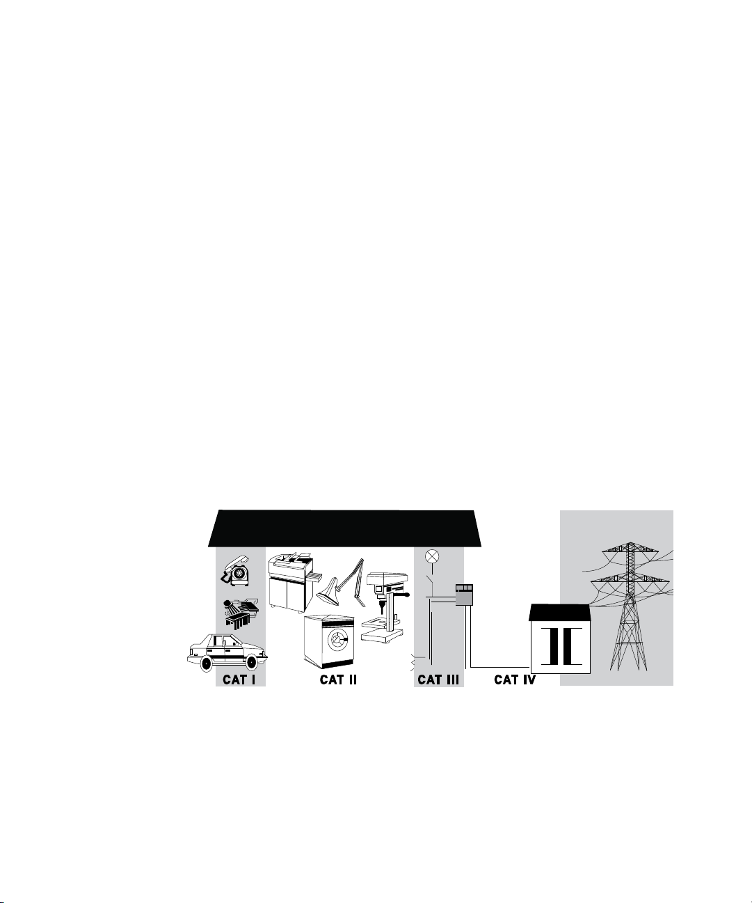
Measurement Category
The Keysight U1273A/U1273AX has a safety rating of CAT III, 1000 V and CAT IV,
600 V.
Measurement CAT I Measurements performed on circuits not directly
connected to the AC mains. Examples are measurements on circuits not derived
from the AC mains and specially protected (internal) mains-derived circuits.
Measurement CAT II Measurements performed on circuits directly connected
to a low-voltage installation. Examples are measurements on household
appliances, portable tools, and similar equipment.
Measurement CAT III Measurements performed in the building installation.
Examples are measurements on distribution boards, circuit- breakers, wiring,
including cables, bus-bars, junction boxes, switches, socket outlets in the fixed
installation, and equipment for industrial use, and some other equipment
including stationary motors with permanent connection to the fixed installation.
Measurement CAT IV Measurements performed at the source of the
low-voltage installation. Examples are electricity meters and measurements on
primary overcurrent protection devices and ripple control units.
8 Keysight U1273A/U1273AX User’s Guide
Page 9

Environmental Conditions
NOTE
This instrument is designed for indoor use and in an area with low condensation.
The table below shows the general environmental requirements for this
instrument.
Environmental conditions Requirements
Operating temperature
Operating humidity
Storage temperature –40 °C to 70 °C
Altitude Up to 3000 meters
Pollution degree Pollution degree II
The U1273A/U1273AX Handheld Digital Multimeter complies with the
following safety and EMC requirements:
–Safety
– EN/IEC 61010-1:2001
– ANSI/UL 61010-1:2004
– U1273A: –20 °C to 55 °C, 0% to 80% RH
– U1273AX: –40 °C to 55 °C, 0% to 80% RH (using Lithium
batteries)
Full accuracy up to 80% RH (relative humidity) for
temperature up to 30 °C, decreasing linearly to 50% RH at
55 °C
– CAN/CSA-C22.2 No. 61010-1-04
–EMC
– IEC61326-1:2005/EN61326-1:2006
– Canada: ICES/NMB-001: Issue 4, June 2006
– Australia/New Zealand: AS/NZS CISPR 11:2004
Keysight U1273A/U1273AX User’s Guide 9
Page 10
Regulatory Markings
The CE mark is a registered trademark
of the European Community. This CE
mark shows that the product complies
with all the relevant European Legal
Directives.
The RCM mark is a registered
trademark of the Australian
Communications and Media Authority.
ICES/NMB-001 indicates that this ISM
device complies with the Canadian
ICES-001.
Cet appareil ISM est confomre a la norme
NMB-001 du Canada.
The CSA mark is a registered trademark of
the Canadian Standards Association.
This instrument complies with the
WEEE Directive (2002/96/EC) marking
requirement. This affixed product label
indicates that you must not discard this
electrical or electronic product in
domestic household waste.
This symbol indicates the time period
during which no hazardous or toxic
substance elements are expected to
leak or deteriorate during normal use.
Forty years is the expected useful life of
the product.
10 Keysight U1273A/U1273AX User’s Guide
Page 11

Waste Electrical and Electronic Equipment (WEEE) Directive 2002/ 96/EC
This instrument complies with the WEEE Directive (2002/96/EC) marking
requirement. This affixed product label indicates that you must not discard this
electrical or electronic product in domestic household waste.
Product category:
With reference to the equipment types in the WEEE directive Annex 1, this
instrument is classified as a “Monitoring and Control Instrument” product.
The affixed product label is as shown below.
Do not dispose in domestic household waste.
To return this unwanted instrument, contact your nearest Keysight Service Center,
or visit http://about.keysight.com/en/companyinfo/environment/takeback.shtml
for more information.
Sales and Technical Support
To contact Keysight for sales and technical support, refer to the support links on
the following Keysight websites:
– www.keysight.com/find/handhelddmm
(product-specific information and support, software and
documentation updates)
– www.keysight.com/find/assist
(worldwide contact information for repair and service)
Keysight U1273A/U1273AX User’s Guide 11
Page 12

THIS PAGE HAS BEEN INTENTIONALLY LEFT BLANK.
12 Keysight U1273A/U1273AX User’s Guide
Page 13

Table of Contents
Safety Symbols . . . . . . . . . . . . . . . . . . . . . . . . . . . . . . . . . . . . . . . . . . . . .5
Safety Considerations . . . . . . . . . . . . . . . . . . . . . . . . . . . . . . . . . . . . . . . .6
Measurement Category . . . . . . . . . . . . . . . . . . . . . . . . . . . . . . . . . . . . . .8
Environmental Conditions . . . . . . . . . . . . . . . . . . . . . . . . . . . . . . . . . . . .9
Regulatory Markings . . . . . . . . . . . . . . . . . . . . . . . . . . . . . . . . . . . . . . . .10
Waste Electrical and Electronic Equipment (WEEE) Directive 2002/96/
EC . . . . . . . . . . . . . . . . . . . . . . . . . . . . . . . . . . . . . . . . . . . . . . . . . . . .11
Product category: . . . . . . . . . . . . . . . . . . . . . . . . . . . . . . . . . . . . . . .11
Sales and Technical Support . . . . . . . . . . . . . . . . . . . . . . . . . . . . . . . . .11
1Introduction
About This Manual . . . . . . . . . . . . . . . . . . . . . . . . . . . . . . . . . . . . . . . . . 22
Documentation map . . . . . . . . . . . . . . . . . . . . . . . . . . . . . . . . . . . . .22
Safety notes . . . . . . . . . . . . . . . . . . . . . . . . . . . . . . . . . . . . . . . . . . . .22
Preparing Your Multimeter . . . . . . . . . . . . . . . . . . . . . . . . . . . . . . . . . . .23
Check the shipment . . . . . . . . . . . . . . . . . . . . . . . . . . . . . . . . . . . . . .23
Install the batteries . . . . . . . . . . . . . . . . . . . . . . . . . . . . . . . . . . . . . . 23
Turn on your multimeter . . . . . . . . . . . . . . . . . . . . . . . . . . . . . . . . . .26
Automatic power-off . . . . . . . . . . . . . . . . . . . . . . . . . . . . . . . . . . . . .26
OLED Auto Dim function . . . . . . . . . . . . . . . . . . . . . . . . . . . . . . . . . . 27
Increase the OLED brightness . . . . . . . . . . . . . . . . . . . . . . . . . . . . . . 27
Select the range . . . . . . . . . . . . . . . . . . . . . . . . . . . . . . . . . . . . . . . . .27
Alerts and warnings during measurement . . . . . . . . . . . . . . . . . . . . 28
Adjust the tilt stand . . . . . . . . . . . . . . . . . . . . . . . . . . . . . . . . . . . . . .30
Connect the IR-USB cable . . . . . . . . . . . . . . . . . . . . . . . . . . . . . . . .30
Power-on options . . . . . . . . . . . . . . . . . . . . . . . . . . . . . . . . . . . . . . .32
Your Multimeter in Brief . . . . . . . . . . . . . . . . . . . . . . . . . . . . . . . . . . . . .33
Dimensions . . . . . . . . . . . . . . . . . . . . . . . . . . . . . . . . . . . . . . . . . . . . .33
Overview . . . . . . . . . . . . . . . . . . . . . . . . . . . . . . . . . . . . . . . . . . . . . . .35
Rotary switch . . . . . . . . . . . . . . . . . . . . . . . . . . . . . . . . . . . . . . . . . . .37
Keypad . . . . . . . . . . . . . . . . . . . . . . . . . . . . . . . . . . . . . . . . . . . . . . . . 39
Keysight U1273A/U1273AX User’s Guide 13
Page 14

Display screen . . . . . . . . . . . . . . . . . . . . . . . . . . . . . . . . . . . . . . . . . . 44
Input terminals . . . . . . . . . . . . . . . . . . . . . . . . . . . . . . . . . . . . . . . . . 50
Cleaning Your Multimeter . . . . . . . . . . . . . . . . . . . . . . . . . . . . . . . . . . . 52
2Making Measurements
Crest Factor . . . . . . . . . . . . . . . . . . . . . . . . . . . . . . . . . . . . . . . . . . . . . . 54
Measuring AC Voltage . . . . . . . . . . . . . . . . . . . . . . . . . . . . . . . . . . . . . . 55
Using the LPF (Low Pass Filter) function for AC measurements . . . 57
Measuring DC Voltage . . . . . . . . . . . . . . . . . . . . . . . . . . . . . . . . . . . . . . 58
Using the Filter Function for DC measurements . . . . . . . . . . . . . . . 61
Measuring AC and DC Signals . . . . . . . . . . . . . . . . . . . . . . . . . . . . . . . . 62
Using the LPF (Low Pass Filter) Function for AC+DC
measurements . . . . . . . . . . . . . . . . . . . . . . . . . . . . . . . . . . . . . . . 64
Making dB Measurements . . . . . . . . . . . . . . . . . . . . . . . . . . . . . . . . . . . 64
Using Z
for Voltage Measurements . . . . . . . . . . . . . . . . . . . . . . . . . 67
LOW
Measuring Resistance . . . . . . . . . . . . . . . . . . . . . . . . . . . . . . . . . . . . . . 69
Measuring conductance . . . . . . . . . . . . . . . . . . . . . . . . . . . . . . . . . . 72
Testing for Continuity . . . . . . . . . . . . . . . . . . . . . . . . . . . . . . . . . . . . . . . 73
Using Smart Ω for Resistance Measurements . . . . . . . . . . . . . . . . . . . 76
Testing Diodes . . . . . . . . . . . . . . . . . . . . . . . . . . . . . . . . . . . . . . . . . . . . 79
Using Auto-diode for Diode Tests . . . . . . . . . . . . . . . . . . . . . . . . . . . . . 83
Measuring Capacitance . . . . . . . . . . . . . . . . . . . . . . . . . . . . . . . . . . . . . 85
Measuring Temperature . . . . . . . . . . . . . . . . . . . . . . . . . . . . . . . . . . . . . 87
Measuring AC or DC Current . . . . . . . . . . . . . . . . . . . . . . . . . . . . . . . . . 91
% Scale of 4-20 mA or 0-20 mA . . . . . . . . . . . . . . . . . . . . . . . . . . . . 97
Measuring Frequency . . . . . . . . . . . . . . . . . . . . . . . . . . . . . . . . . . . . . . 100
Measuring pulse width . . . . . . . . . . . . . . . . . . . . . . . . . . . . . . . . . . 103
Measuring duty cycle . . . . . . . . . . . . . . . . . . . . . . . . . . . . . . . . . . . 104
3 Multimeter Features
Making Relative Measurements (Null) . . . . . . . . . . . . . . . . . . . . . . . . . 106
Making Scale Transfers (Scale) . . . . . . . . . . . . . . . . . . . . . . . . . . . . . . 108
14 Keysight U1273A/U1273AX User’s Guide
Page 15

Capturing Maximum and Minimum Values (MaxMin) . . . . . . . . . . . . .110
Capturing Peak Values (Peak) . . . . . . . . . . . . . . . . . . . . . . . . . . . . . . .112
Freezing the Display (TrigHold and AutoHold) . . . . . . . . . . . . . . . . . .114
Recording Measurement Data (Data Logging) . . . . . . . . . . . . . . . . . .115
Performing manual logs (HAND) . . . . . . . . . . . . . . . . . . . . . . . . . . .116
Performing interval logs (AUTO) . . . . . . . . . . . . . . . . . . . . . . . . . . .116
Performing event logs (TRIG) . . . . . . . . . . . . . . . . . . . . . . . . . . . . .118
Reviewing Previously Recorded Data (View) . . . . . . . . . . . . . . . . . . . .120
Sanitizing the Log Memories . . . . . . . . . . . . . . . . . . . . . . . . . . . . . .121
4 Multimeter Setup Options
Using the Setup Menu . . . . . . . . . . . . . . . . . . . . . . . . . . . . . . . . . . . . .124
Editing numerical values . . . . . . . . . . . . . . . . . . . . . . . . . . . . . . . . .125
Setup Menu Summary . . . . . . . . . . . . . . . . . . . . . . . . . . . . . . . . . . . . .127
Setup Menu Items . . . . . . . . . . . . . . . . . . . . . . . . . . . . . . . . . . . . . . . . .132
Changing the variation count . . . . . . . . . . . . . . . . . . . . . . . . . . . . .132
Changing the recording option . . . . . . . . . . . . . . . . . . . . . . . . . . . .132
Changing the sample interval duration . . . . . . . . . . . . . . . . . . . . . .133
Changing the decibel display . . . . . . . . . . . . . . . . . . . . . . . . . . . . .133
Changing the custom dBm reference impedance . . . . . . . . . . . . .134
Changing the thermocouple type . . . . . . . . . . . . . . . . . . . . . . . . . .135
Changing the temperature unit . . . . . . . . . . . . . . . . . . . . . . . . . . . .135
Changing the % scale range . . . . . . . . . . . . . . . . . . . . . . . . . . . . . .136
Changing the continuity alert . . . . . . . . . . . . . . . . . . . . . . . . . . . . .137
Changing the minimum measurable frequency . . . . . . . . . . . . . . .137
Changing the beep frequency . . . . . . . . . . . . . . . . . . . . . . . . . . . . .138
Changing the auto power-off (APO) timer . . . . . . . . . . . . . . . . . . .138
Changing the OLED behavior . . . . . . . . . . . . . . . . . . . . . . . . . . . . .139
Changing the power-on melody . . . . . . . . . . . . . . . . . . . . . . . . . . .139
Changing the power-on greetings . . . . . . . . . . . . . . . . . . . . . . . . .140
Changing the baud rate . . . . . . . . . . . . . . . . . . . . . . . . . . . . . . . . . .141
Changing the data bits . . . . . . . . . . . . . . . . . . . . . . . . . . . . . . . . . .141
Changing the parity check . . . . . . . . . . . . . . . . . . . . . . . . . . . . . . . .142
Enabling the echo feature . . . . . . . . . . . . . . . . . . . . . . . . . . . . . . . .142
Keysight U1273A/U1273AX User’s Guide 15
Page 16

Enabling the print feature . . . . . . . . . . . . . . . . . . . . . . . . . . . . . . . . 143
Enabling the overvoltage alert . . . . . . . . . . . . . . . . . . . . . . . . . . . . 143
Changing the user scale conversion value and unit . . . . . . . . . . . . 144
Enabling smooth mode . . . . . . . . . . . . . . . . . . . . . . . . . . . . . . . . . . 144
Resetting the multimeter’s setup options . . . . . . . . . . . . . . . . . . . 145
Changing the battery type . . . . . . . . . . . . . . . . . . . . . . . . . . . . . . . 146
Enabling the filter . . . . . . . . . . . . . . . . . . . . . . . . . . . . . . . . . . . . . . 146
5Characteristics and Specifications
A Shift Functions Using the Shift Key
B Dual Display Combinations Using the Dual Key
16 Keysight U1273A/U1273AX User’s Guide
Page 17

List of Figures
Figure 1-1 Installing the batteries . . . . . . . . . . . . . . . . . . . . . . . . . . . 24
Figure 1-2 Change battery display . . . . . . . . . . . . . . . . . . . . . . . . . .25
Figure 1-3 Input warning display (A INPUT) . . . . . . . . . . . . . . . . . . .29
Figure 1-4 Input warning display (mA INPUT). . . . . . . . . . . . . . . . . .29
Figure 1-5 Tilt-stand adjustment and IR-USB cable connection . . .30
Figure 1-6 Keysight GUI Data Logger Software . . . . . . . . . . . . . . . .31
Figure 1-7 Width dimensions. . . . . . . . . . . . . . . . . . . . . . . . . . . . . . .33
Figure 1-8 Height and depth dimensions . . . . . . . . . . . . . . . . . . . . .34
Figure 1-9 Front panel . . . . . . . . . . . . . . . . . . . . . . . . . . . . . . . . . . . .35
Figure 1-10 Rear panel . . . . . . . . . . . . . . . . . . . . . . . . . . . . . . . . . . . .36
Figure 1-11 U1273A/U1273AX rotary switch . . . . . . . . . . . . . . . . . . .37
Figure 1-12 Keys . . . . . . . . . . . . . . . . . . . . . . . . . . . . . . . . . . . . . . . . .39
Figure 1-13 Display screen example (single display) . . . . . . . . . . . . .44
Figure 1-14 Display screen example (dual display). . . . . . . . . . . . . . .44
Figure 1-15 Connector terminals. . . . . . . . . . . . . . . . . . . . . . . . . . . . .50
Figure 2-1 AC voltage display . . . . . . . . . . . . . . . . . . . . . . . . . . . . . . 55
Figure 2-2 Measuring AC voltage . . . . . . . . . . . . . . . . . . . . . . . . . . .56
Figure 2-3 AC voltage with LPF display. . . . . . . . . . . . . . . . . . . . . . .57
Figure 2-4 DC voltage display . . . . . . . . . . . . . . . . . . . . . . . . . . . . . .58
Figure 2-5 Measuring DC voltage . . . . . . . . . . . . . . . . . . . . . . . . . . .60
Figure 2-6 Filter for DC voltage measurements . . . . . . . . . . . . . . . .61
Figure 2-7 AC+DC voltage display. . . . . . . . . . . . . . . . . . . . . . . . . . .63
Figure 2-8 AC+DC current display. . . . . . . . . . . . . . . . . . . . . . . . . . .63
Figure 2-9 Low Pass Filter(LPF) for AC+DC voltage measurements 64
Figure 2-10 dBm display . . . . . . . . . . . . . . . . . . . . . . . . . . . . . . . . . . .65
Figure 2-11 dBV display. . . . . . . . . . . . . . . . . . . . . . . . . . . . . . . . . . . .67
Figure 2-12 Z
Figure 2-13 Resistance display . . . . . . . . . . . . . . . . . . . . . . . . . . . . . .70
Figure 2-14 Measuring resistance . . . . . . . . . . . . . . . . . . . . . . . . . . . .71
Figure 2-15 Continuity operation. . . . . . . . . . . . . . . . . . . . . . . . . . . . .74
Figure 2-16 Testing for continuity . . . . . . . . . . . . . . . . . . . . . . . . . . . .75
Figure 2-17 Smart Ω (with bias voltage) display. . . . . . . . . . . . . . . . .77
Figure 2-18 Smart Ω (with leakage current) display. . . . . . . . . . . . . .77
Figure 2-19 Measuring leakage current . . . . . . . . . . . . . . . . . . . . . . . 78
display. . . . . . . . . . . . . . . . . . . . . . . . . . . . . . . . . . .68
LOW
Keysight U1273A/U1273AX User’s Guide 17
Page 18

Figure 2-20 Diode display . . . . . . . . . . . . . . . . . . . . . . . . . . . . . . . . . . 79
Figure 2-21 Open diode display . . . . . . . . . . . . . . . . . . . . . . . . . . . . . 80
Figure 2-22 Testing a forward-bias diode. . . . . . . . . . . . . . . . . . . . . . 81
Figure 2-23 Testing a reverse-bias diode . . . . . . . . . . . . . . . . . . . . . . 82
Figure 2-24 Auto-diode display (GOOD status) . . . . . . . . . . . . . . . . . 84
Figure 2-25 Auto-diode display (NGOOD status) . . . . . . . . . . . . . . . . 84
Figure 2-26 Capacitance display. . . . . . . . . . . . . . . . . . . . . . . . . . . . . 85
Figure 2-27 Measuring capacitance . . . . . . . . . . . . . . . . . . . . . . . . . . 86
Figure 2-28 Temperature display . . . . . . . . . . . . . . . . . . . . . . . . . . . . 87
Figure 2-29 Measuring surface temperature . . . . . . . . . . . . . . . . . . . 89
Figure 2-30 Temperature measurement without ambient
compensation . . . . . . . . . . . . . . . . . . . . . . . . . . . . . . . 90
Figure 2-31 DC current display . . . . . . . . . . . . . . . . . . . . . . . . . . . . . . 92
Figure 2-32 Measuring DC current . . . . . . . . . . . . . . . . . . . . . . . . . . . 94
Figure 2-33 Measuring AC current . . . . . . . . . . . . . . . . . . . . . . . . . . . 95
Figure 2-34 Current measurement setup . . . . . . . . . . . . . . . . . . . . . . 96
Figure 2-35 4-20 mA % Scale display. . . . . . . . . . . . . . . . . . . . . . . . . 97
Figure 2-36 Measuring DC current using the 0-20 mA % scale . . . . 99
Figure 2-37 Frequency, pulse width, and duty cycle
measurements . . . . . . . . . . . . . . . . . . . . . . . . . . . . . 101
Figure 2-38 Frequency display . . . . . . . . . . . . . . . . . . . . . . . . . . . . . 102
Figure 2-39 Pulse width display . . . . . . . . . . . . . . . . . . . . . . . . . . . . 103
Figure 2-40 Duty cycle display . . . . . . . . . . . . . . . . . . . . . . . . . . . . . 104
Figure 3-1 Null display . . . . . . . . . . . . . . . . . . . . . . . . . . . . . . . . . . 106
Figure 3-2 Null operation . . . . . . . . . . . . . . . . . . . . . . . . . . . . . . . . 107
Figure 3-3 Scale operation . . . . . . . . . . . . . . . . . . . . . . . . . . . . . . . 109
Figure 3-4 MaxMin display . . . . . . . . . . . . . . . . . . . . . . . . . . . . . . . 110
Figure 3-5 Peak display . . . . . . . . . . . . . . . . . . . . . . . . . . . . . . . . . . 112
Figure 3-6 Peak mode operation. . . . . . . . . . . . . . . . . . . . . . . . . . . 113
Figure 3-7 Manual log display. . . . . . . . . . . . . . . . . . . . . . . . . . . . . 116
Figure 3-8 Interval log display. . . . . . . . . . . . . . . . . . . . . . . . . . . . . 117
Figure 3-9 Event log display . . . . . . . . . . . . . . . . . . . . . . . . . . . . . . 119
Figure 3-10 View display . . . . . . . . . . . . . . . . . . . . . . . . . . . . . . . . . . 120
Figure 3-11 Empty view display . . . . . . . . . . . . . . . . . . . . . . . . . . . . 120
18 Keysight U1273A/U1273AX User’s Guide
Page 19

List of Tables
Table 1-1 Power-on options . . . . . . . . . . . . . . . . . . . . . . . . . . . . .32
Table 1-2 Front panel parts . . . . . . . . . . . . . . . . . . . . . . . . . . . . .35
Table 1-3 Rear panel parts . . . . . . . . . . . . . . . . . . . . . . . . . . . . . .36
Table 1-4 U1273A/U1273AX rotary switch functions . . . . . . . . .38
Table 1-5 Keypad functions . . . . . . . . . . . . . . . . . . . . . . . . . . . . .40
Table 1-6 General annunciators . . . . . . . . . . . . . . . . . . . . . . . . . .45
Table 1-7 Measurement units display . . . . . . . . . . . . . . . . . . . . .48
Table 1-8 Analog bar graph display . . . . . . . . . . . . . . . . . . . . . . .49
Table 1-9 Terminal connections for different measuring
functions . . . . . . . . . . . . . . . . . . . . . . . . . . . . . . . . .51
Table 2-1 Rotary switch positions allowing AC voltage
measurements . . . . . . . . . . . . . . . . . . . . . . . . . . . . .55
Table 2-2 Rotary switch positions allowing AC voltage
measurements with LPF . . . . . . . . . . . . . . . . . . . . .57
Table 2-3 Rotary switch positions allowing DC voltage
measurements . . . . . . . . . . . . . . . . . . . . . . . . . . . . .58
Table 2-4 Rotary switch positions allowing AC+DC signal
measurements . . . . . . . . . . . . . . . . . . . . . . . . . . . . .62
Table 2-5 Rotary switch positions allowing dBm measurements 65
Table 2-6 Rotary switch positions allowing dBV measurements 66
Table 2-7 Rotary switch positions allowing Z
measurements . . . . . . . . . . . . . . . . . . . . . . . . . . . . .67
Table 2-8 Rotary switch position allowing resistance
measurements . . . . . . . . . . . . . . . . . . . . . . . . . . . . .69
Table 2-9 Rotary switch position allowing continuity tests . . . . .73
Table 2-10 Threshold resistance values . . . . . . . . . . . . . . . . . . . . .73
Table 2-11 Rotary switch position allowing Smart Ω
measurements . . . . . . . . . . . . . . . . . . . . . . . . . . . . .76
Table 2-12 Rotary switch position allowing diode tests . . . . . . . .79
Table 2-13 Rotary switch position allowing auto-diode tests . . . .83
Table 2-14 Auto-diode voltage thresholds . . . . . . . . . . . . . . . . . .83
Table 2-15 Rotary switch position allowing capacitance
measurements . . . . . . . . . . . . . . . . . . . . . . . . . . . . .85
Table 2-16 Rotary switch position allowing temperature
LOW
Keysight U1273A/U1273AX User’s Guide 19
Page 20

measurements . . . . . . . . . . . . . . . . . . . . . . . . . . . . 87
Table 2-17 Rotary switch positions allowing current
measurements . . . . . . . . . . . . . . . . . . . . . . . . . . . . 91
Table 2-18 Rotary switch positions allowing current
measurements . . . . . . . . . . . . . . . . . . . . . . . . . . . . 97
Table 2-19 % Scale measurement range . . . . . . . . . . . . . . . . . . . 98
Table 2-20 Rotary switch positions allowing frequency
measurements . . . . . . . . . . . . . . . . . . . . . . . . . . . 100
Table 3-1 Available scale conversions . . . . . . . . . . . . . . . . . . . . 108
Table 3-2 Data logging maximum capacity . . . . . . . . . . . . . . . . 115
Table 3-3 Event log trigger conditions . . . . . . . . . . . . . . . . . . . 118
Table 4-1 Setup menu key functions . . . . . . . . . . . . . . . . . . . . . 124
Table 4-2 Setup menu item descriptions . . . . . . . . . . . . . . . . . 127
Table 4-3 Filter (LPF) options . . . . . . . . . . . . . . . . . . . . . . . . . . . 147
Table 4-4 Firmware version 1.64 or older . . . . . . . . . . . . . . . . . 147
Table 4-5 Firmware version 1.95 or newer . . . . . . . . . . . . . . . . 147
Table A-1 U1273A/U1273AX default and shift functions . . . . . 152
Table B-1 U1273A/U1273AX dual display combinations . . . . . 156
20 Keysight U1273A/U1273AX User’s Guide
Page 21

Keysight U1273A/U1273AX Handheld Digital Multimeter
User’s Guide
1 Introduction
About This Manual 22
Preparing Your Multimeter 23
Your Multimeter in Brief 33
Cleaning Your Multimeter 52
This chapter lists the package contents for the U1273A/U1273AX handheld
digital multimeter and teaches you how to set up your multimeter for the first
time. An introduction to all the features of the multimeter is also given.
21
Page 22

1Introduction
CAUTION
WARNING
About This Manual
Documentation map
The following manuals and software are available for your multimeter. For the very
latest version, please visit our website at http://www.keysight.com/find/
hhTechLib.
Check the manual revision on the first page of each manual.
– User’s Guide. This manual.
– Quick Start Guide. Printed copy for outdoor use, included with shipment.
– Service Guide. Free download at the Keysight website.
– Keysight GUI Data Logger Software, Help, and Quick Start Guide. Free
download at the Keysight website.
Safety notes
The following safety notes are used throughout this manual. Familiarize yourself
with each of the notes and its meaning before operating your multimeter. More
pertinent safety notes for using this product are located under the “Safety
Symbols” section.
Caution denotes a hazard. It calls attention to a procedure that, if not
correctly performed or adhered to, could result in damage to or destruction
of the product. Do not proceed beyond a caution notice until the indicated
conditions are fully understood and met.
Warning denotes a hazard. It calls attention to a procedure which, if not
correctly performed or adhered to, could result in injury or loss of life. Do not
proceed beyond a warning note until the indicated conditions are fully
understood and met.
22 Keysight U1273A/U1273AX User’s Guide
Page 23

Preparing Your Multimeter
CAUTION
Check the shipment
When you receive your multimeter, check the shipment according to the following
procedure.
1 Inspect the shipping container for damage. Signs of damage may include a
dented or torn shipping container or cushioning material that indicates signs
of unusual stress or compacting. Save the packaging material in case the
multimeter needs to be returned.
2 Carefully remove the contents from the shipping container, and verify that the
standard accessories and your ordered options are included in the shipment
according to the standard shipped items list found in the printed copy of the
U1273A/U1273AX Quick Start Guide.
3 For any question or problems, refer to the Keysight contact numbers on the
back of this manual.
Install the batteries
Introduction 1
Your multimeter is powered by four 1.5 V AAA batteries (included with the
shipment). When you receive your multimeter, the AAA batteries are not installed.
Use the following procedure to install the batteries.
Before you proceed with the batteries installation, remove all cable
connections to the terminals and ensure that the rotary switch is at the
OFF position. Use only the battery type specified in the datasheet at
http://literature.cdn.keysight.com/litweb/pdf.
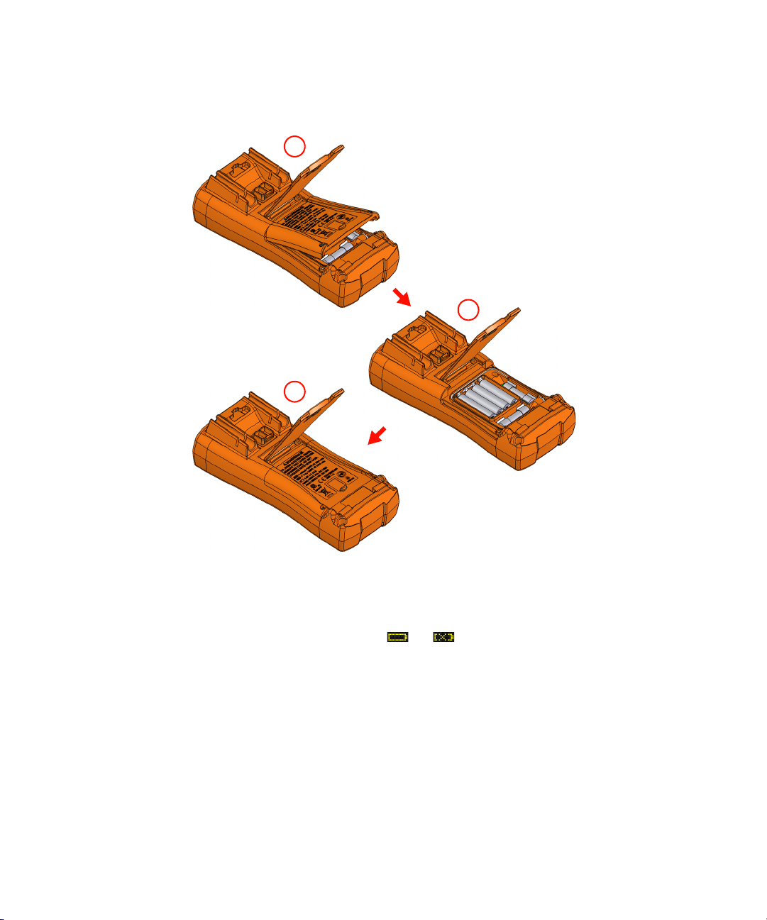
1 Open the battery cover. Lift the tilt stand, loosen the screws with a suitable
Phillips screwdriver, and remove the battery cover as shown in Figure 1-1.
2 Insert the battery. Observe the proper battery polarity. The terminal ends of
each battery are indicated inside the battery compartment.
3 Close the battery cover. Place the battery cover back in its original position
and tighten the screws.
Keysight U1273A/U1273AX User’s Guide 23
Page 24
1Introduction
1
2
3
Figure 1-1 Installing the batteries
The battery level indicator in the lower left-hand corner of the display indicates
the relative condition of the batteries. Replace the batteries as soon as possible
when the low battery indicator ( ↔ ) is shown.
When the Change Battery warning (Figure 1-2) is shown on the display, the
multimeter will power-off automatically after 5 seconds (even if the APO feature is
disabled).
24 Keysight U1273A/U1273AX User’s Guide
Page 25

Introduction 1
WARNING
CAUTION
Figure 1-2 Change battery display
To avoid false readings, which could lead to possible electric shock or
personal injury, replace the battery as soon as the low battery indicator
appears. Do not discharge the battery by shorting the battery or reverse the
battery polarity in any of the subjects.
To avoid instruments being damage from battery leakage:
– Always remove dead batteries immediately.
– Always remove the batteries and store them separately if the multimeter
is not going to be used for a long period.
Keysight U1273A/U1273AX User’s Guide 25
Page 26

1Introduction
Turn on your multimeter
To power ON your multimeter, turn the rotary switch to any other position.
To power OFF your multimeter, turn the rotary switch to the position.
Automatic power-off
Your multimeter automatically turns off if the rotary switch is not moved or a key is
not pressed for 10 minutes (default). Pressing any key will turn the multimeter
back on after it is powered off automatically.
To change the timer period or completely disable the automatic power-off, refer
to “Changing the auto power-off (APO) timer” on page 138.
26 Keysight U1273A/U1273AX User’s Guide
Page 27

OLED Auto Dim function
NOTE
Setup
Setup
A
u
t
o
R
a
n
g
e
Your multimeter’s OLED automatically dims if the rotary switch is not moved or a
key is not pressed for 90 seconds (default). This auto dim behavior is enabled by
default. Pressing any key or changing the rotary switch position will cancel this
effect and reset the auto dim timer.
To disable the auto dim, refer to “Changing the OLED behavior” on page 139.
Increase the OLED brightness
The auto dim function is enabled by default. Refer to “Changing the OLED
behavior” on page 139 to disable the auto dim function before you can manually
change the OLED brightness.
If viewing the display becomes difficult in low-light conditions, press to
change the OLED brightness.
The LOW, MEDIUM, or HIGH setting must be selected in the multimeter’s setup
(browse to Menu 3 > BACKLIT) prior to this action.
Introduction 1
Pressing repeatedly will increase the OLED brightness from low to medium to
high (and back to low again).
You are advised to select an suitable brightness level based on your needs to
conserve battery life if you wish to control the OLED brightness level manually.
Select the range
The multimeter’s selected range is always displayed above the right-hand end of
the bar graph, as the range indicator. Pressing switches the multimeter
between manual and auto-ranging. It also cycles through the available
multimeter ranges when manual ranging is enabled.
Auto-ranging is convenient because the multimeter automatically selects an
appropriate range for sensing and displaying each measurement. However,
manual ranging results in better performance, because the multimeter does not
have to determine which range to use for each measurement.
Keysight U1273A/U1273AX User’s Guide 27
Page 28

1Introduction
NOTE
A
u
t
o
R
a
n
g
e
A
u
t
o
R
a
n
g
e
A
u
t
o
R
a
n
g
e
WARNING
The range is fixed for diode tests, temperature, and Z
In auto-range, the multimeter selects the lowest range to display the highest
available precision (resolution) for the input signal. If manual range is already
enabled, press for more than 1 second to enter the auto-ranging mode.
If auto-ranging is enabled, press to enter the manual range mode.
Each additional press of sets the multimeter to the next higher range,
unless it is already in the highest range, at which point the range switches to the
lowest range.
Alerts and warnings during measurement
Voltage alert
For your own safety, please do not ignore the voltage alert. When the
multimeter cautions you with a voltage alert, you are advised to take note of
the high voltage existence and to use precautions when performing
measurements.
Your multimeter provides a voltage alert for voltage measurements in both
auto-ranging and manual range modes. The multimeter starts beeping
periodically once the measured voltage exceeds the alert value (regardless of
polarity) set in the setup menu.
By default, this feature is turned off. Be sure to set the alert voltage according to
your test requirements. To change the alert voltage level, refer to “Enabling the
overvoltage alert” on page 143.
measurements.
LOW
Hazardous voltage indication
The multimeter will also display the hazardous voltage ( ) symbol as an early
precaution when the measured voltage is equal to or greater than 30 V in all
voltage measurement modes.
28 Keysight U1273A/U1273AX User’s Guide
Page 29

Introduction 1
CAUTION
Input warning
To avoid circuit damage and possibly blowing the mul timeter’s current fuse,
do not place the probes across (in parallel with) a powered circuit when a
lead is plugged into a current terminal. This causes a short circuit because
the resistance through the multimeter's current terminals is very low.
The multimeter emits a continuous beep and displays Error ON A INPUT or Error
ON mA INPUT when the test lead is inserted into the µA mA or A input terminal
but the rotary switch is not set to the correct current position.
Figure 1-3 Input warning display (A INPUT)
Figure 1-4 Input warning display (mA INPUT)
This warning is intended to stop you from attempting to measure voltage,
continuity, resistance, capacitance, diode, or temperature values when the leads
are plugged into a current terminal.
Keysight U1273A/U1273AX User’s Guide 29
Page 30

1Introduction
To PC (host)
IR-USB cable
Pull until maximum reach
Adjust the tilt stand
To adjust the multimeter to a 60° standing position, pull the tilt-stand outward to
its maximum reach.
Figure 1-5 Tilt-stand ad justment and IR-USB cable connection
Connect the IR-USB cable
You can use the IR communication link (IR communication port, located at the
rear panel) and the Keysight GUI Data Logger software to control your multimeter
remotely, perform data logging operations, and transfer the contents of your
multimeter’s memory to a PC.
Ensure that the Keysight logo on the U1173A IR-USB cable (purchased
separately) connected to the multimeter is facing up. Firmly push the IR head into
the multimeter’s IR communication port until it snaps into place (see Figure 1-5).
Refer to the Keysight GUI Data Logger Software Help and Quick Start Guide for
more information on the IR communication link and the Keysight GUI Data Logger
software.
30 Keysight U1273A/U1273AX User’s Guide
Page 31

Introduction 1
Figure 1-6 Keysight GUI Data Logger Software
The Keysight GUI Data Logger software and its supporting documents (Help and
Quick Start Guide) are available for free download at http://www.keysight.com/
find/hhTechLib.
You may purchase a U1173A IR-USB cable from a Keysight Sales Office nearest to
you.
Keysight U1273A/U1273AX User’s Guide 31
Page 32

1Introduction
S
c
a
l
e
N
u
l
l
H
z
%
m
s
L
o
g
Exit
Dual
P
e
a
k
M
a
x
M
i
n
A
u
t
o
R
a
n
g
e
A
u
t
o
T
r
i
g
H
o
l
d
S
h
i
f
t
V
i
e
w
E
s
c
Power-on options
Some options can be selected only while you turn the multimeter on. These
power-on options are listed in the table below. To select a power-on option, press
and hold the specified key while turning the rotary switch to any other position
(OFF to ON). Power-on options remain selected until the multimeter is turned off.
Tab le 1-1 Power-on options
Key Description
Checks firmware version. The multimeter’s firmware version will be shown on the primary display. Press
any key to exit this mode.
Simulates the Auto Power-Off (APO) mode. Press any key to turn the multimeter back on and resume
normal operation.
Displays the factory default power-on greeting. Press any key to exit this mode.
Auto Power-Off (APO) is disabled until the multimeter is turned off. To permanently disable APO, see
“Changing the auto power-off (APO) timer” on page 138.
Displays the user-defined power-on greeting. Press any key to exit this mode.
Tests the OLED. All OLED pixels are lighted. Use this mode to verify that there are no dead OLED pixels.
Press any key to exit this mode.
Smooth is enabled until the multimeter is turned off. To permanently enable Smooth, see “Enabling
smooth mode” on page 144.
32 Keysight U1273A/U1273AX User’s Guide
Page 33

Your Multimeter in Brief
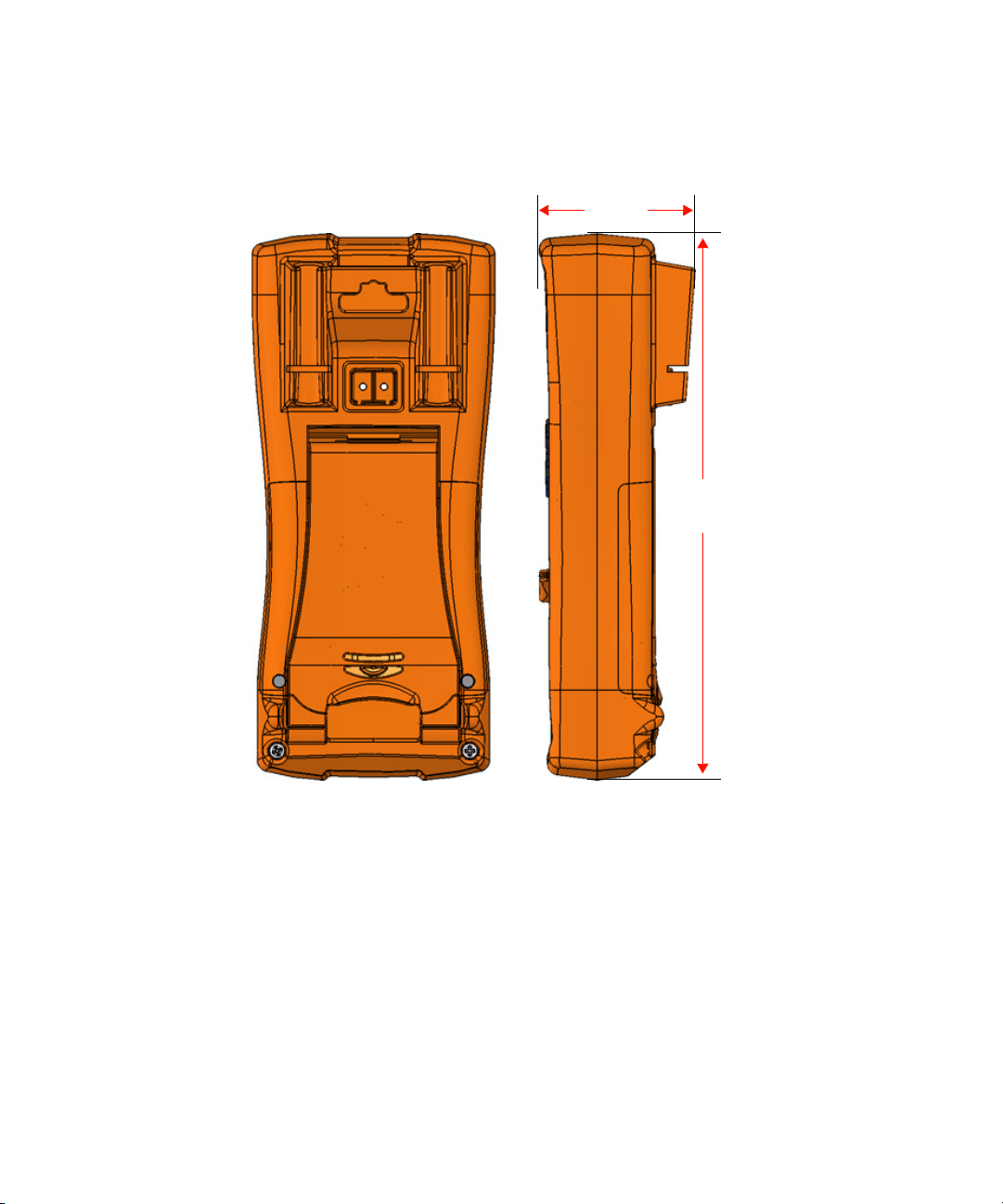
92 mm
Dimensions
Front view
Introduction 1
Figure 1-7 Width dimensions
Keysight U1273A/U1273AX User’s Guide 33
Page 34
1Introduction
207 mm
59 mm
Rear and side view
Figure 1-8 Height and depth dimensions
34 Keysight U1273A/U1273AX User’s Guide
Page 35

Overview
Front panel
The front panel parts of your multimeter are described in this section. Click the
respective “Learn more” pages for more information on each part.
Introduction 1
Figure 1-9 Front panel
Table 1-2 Front panel parts
Legend Description Learn more on:
1 Display screen page 44
2 Keypad page 39
3 Rotary switch page 37
4 Terminals page 50
Keysight U1273A/U1273AX User’s Guide 35
Page 36

1Introduction
2
1
4
3
Rear panel
The rear panel parts of your multimeter are described in this section. Click the
respective “Learn more” pages for more information on each part.
Figure 1-10 Rear panel
Tab le 1-3 Rear panel parts
Legend Description Learn more on:
1 Test probe holders -
2 IR communication port page 30
3 Battery and fuse access cover page 23
4 Tilt stand page 30
36 Keysight U1273A/U1273AX User’s Guide
Page 37
Rotary switch
NOTE
WARNING
S
h
i
f
t
V
i
e
w
E
s
c
S
h
i
f
t
V
i
e
w
E
s
c
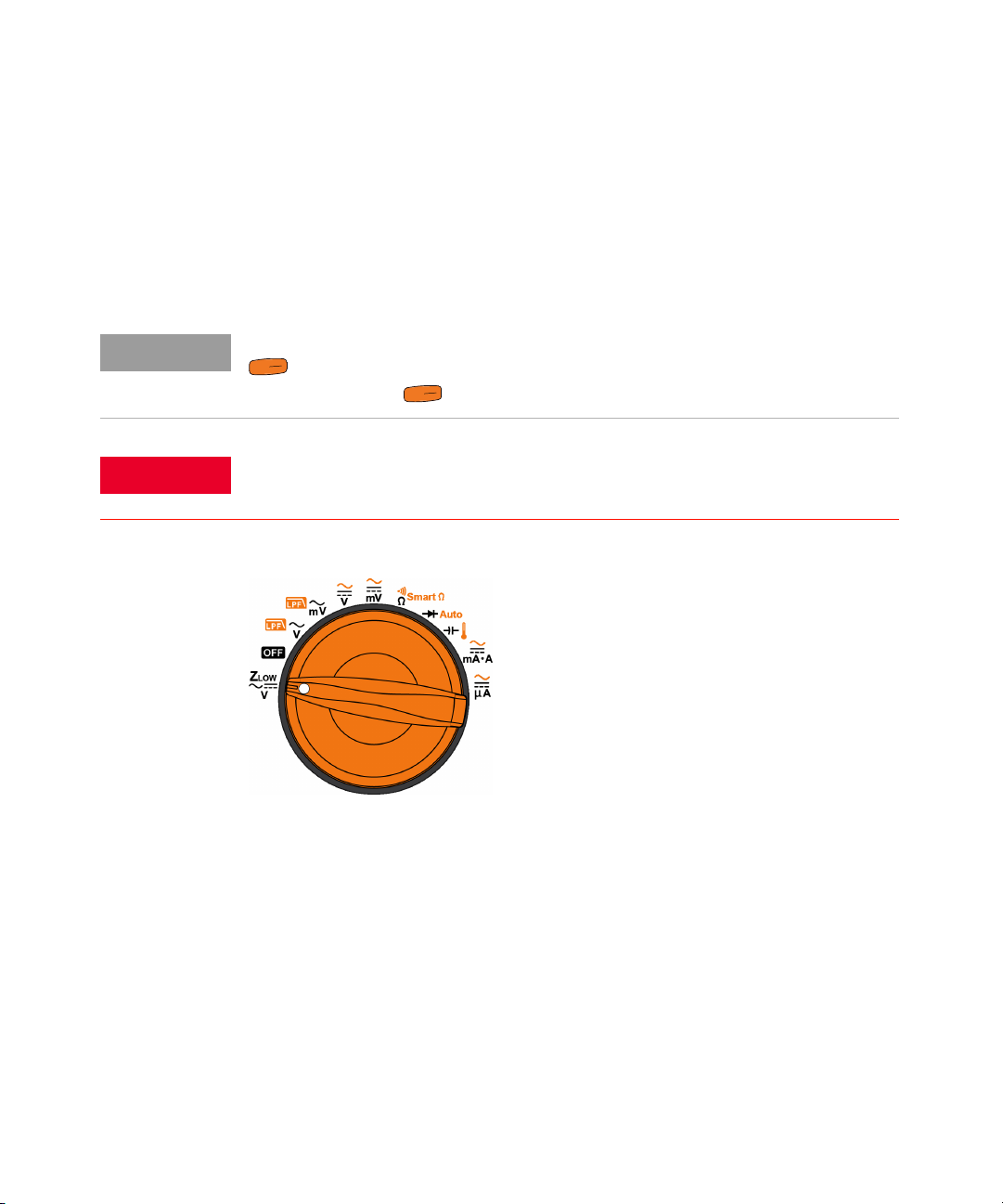
The measurement functions for each rotary switch position are described in
Table 1-4. Turning the rotary switch changes the measurement function and
resets all other measurement options.
Click the respective “Learn more” pages for more information on each function.
Some rotary switch positions have a shifted function printed in orange. Press
to switch between the shifted and default function. See page 43 for more
information on the key.
Remove the test leads from the measuring source or target before changing
the rotary switch position.
Introduction 1
Figure 1-11 U1273A/U1273AX rotary switch
Each position of the U1273A/U1273AX rotary switch (shown in Figure 1-11) is
described in Tab le 1 -4.
Keysight U1273A/U1273AX User’s Guide 37
Page 38

1Introduction
Z
LOW
Smart
Auto
Tab le 1-4 U1273A/U1273AX rotary switch functions
Legend Description Learn more on:
Low impedance AC or DC voltage measurement for
eliminating ghost voltages
page 67
Off page 26
AC voltage measurement with Low Pass Filter
AC voltage measurement (up to millivolts) with Low Pass
page 54 and page 57
Filter
AC, DC, or AC+DC voltage measurement
page 54, page 58, and page 61
AC, DC, or AC+DC voltage measurement (up to millivolts)
Resistance measurement, Continuity test, or Resistance
measurement with offset compensation
page 69, page 73, and page 76
Diode test or Auto-diode test page 79 and page 83
Capacitance or Temperature measurement page 85 and page 87
AC, DC, or AC+DC current measurement
page 91 and page 61
AC, DC, or AC+DC current measurement (up to
microamperes)
38 Keysight U1273A/U1273AX User’s Guide
Page 39

Keypad
Introduction 1
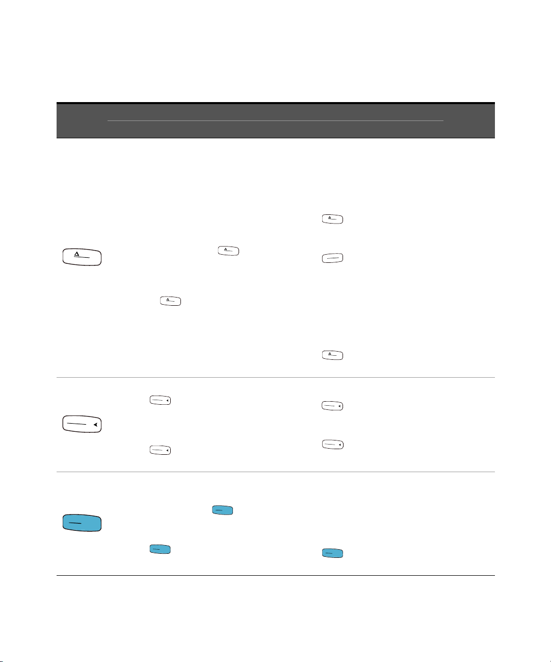
The operation of each key is explained below. Pressing a key enables a function,
displays a related symbol, and emits a beep. Turning the rotary switch to another
position resets the current operation of the key. Click the respective “Learn more”
pages for more information on each function.
Figure 1-12 Keys
Keysight U1273A/U1273AX User’s Guide 39
Page 40
1Introduction
S
c
a
l
e
N
u
l
l
S
c
a
l
e
N
u
l
l
S
c
a
l
e
N
u
l
l
S
c
a
l
e
N
u
l
l
H
z
%
m
s
L
o
g
S
c
a
l
e
N
u
l
l
P
e
a
k
M
a
x
M
i
n
P
e
a
k
M
a
x
M
i
n
P
e
a
k
M
a
x
M
i
n
P
e
a
k
M
a
x
M
i
n
P
e
a
k
M
a
x
M
i
n
A
u
t
o
T
r
i
g
H
o
l
d
A
u
t
o
T
r
i
g
H
o
l
d
A
u
t
o
T
ri
g
H
o
l
d
A
u
t
o
T
ri
g
H
o
l
d
Tab le 1-5 Keypad functions
Legend
Function when pressed for:
Less than 1 second More than 1 second
Sets the Null/Relative mode.
– The displayed value is saved as a reference
to be subtracted from subsequent
measurements.
– While in Null mode, press again to
view the stored reference value that has
been saved. The display will return to
normal after 3 seconds.
– Pressing while the relative value is
being displayed will cancel the Null mode.
Starts the MaxMin recording.
– Press again to cycle through
maximum (REC MAX), minimum (REC
MIN), average (REC AVG), and present
(REC NOW) readings.
– Press for more than 1 second to exit
this mode.
Sets the Scale mode for the specified ratio and
unit display. (Only applicable for voltage
measurements.)
– The most recently saved (or default) ratio
and unit will be shown on the primary
and secondary displays.
–Press while the SCALE symbol is
flashing to cycle through the available
ratio and unit displays.
–Press while the SCALE symbol is
flashing to save the selected ratio and
unit and to start the conversion, or
– While the SCALE symbol is flashing, if
no activity is detected after 3 seconds,
the conversion will begin (with the
specified ratio and unit shown on the
primary display).
– Press for more than 1 second to
cancel the Scale transfer mode.
Starts and stops the Peak recording.
– Press again to switch between the
maximum (P-HOLD+) and minimum
(P-HOLD–) peak readings.
– Press for more than 1 second to
exit this mode.
Learn more
on:
page 106
and
page 108
page 110
and
page 112
Freezes the present reading in the display
(T-HOLD mode).
– In TrigHold mode, press to manually
trigger the holding of the next measured
value.
– Press for more than 1 second to exit
this mode.
Automatically freezes the present reading
once the reading is stable (A-HOLD mode)
– In AutoHold mode, the reading is
updated automatically once the reading
is stable and the count setting is
exceeded.
– Press for more than 1 second to
exit this mode.
page 114
40 Keysight U1273A/U1273AX User’s Guide
Page 41

Table 1-5 Keypad functions (continued)
Exit
Dual
Setup
P
e
a
k
M
a
x
M
i
n
A
u
t
o
R
a
n
g
e
Exit
Dual
Setup
H
z
%
m
s
L
o
g
H
z
%
m
s
L
o
g
S
h
i
f
t
V
i
e
w
E
s
c
Setup
Introduction 1
Legend
Function when pressed for:
Less than 1 second More than 1 second
Switches between the dual-combination displays
(if available).
Changes the OLED brightness when LOW,
MEDIUM, or HIGH setting is selected in the
multimeter’s setup.
Exits the Hold, Null, MaxMin, Peak, frequency
test, and dual display modes.
Enters or exits the setup menu.
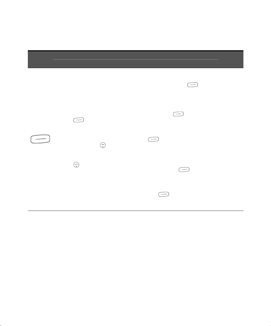
– In the setup menu, press or
to navigate through the menu
pages. Press or at each menu
page to move the cursor to a specific
menu item.
– Press to edit the selected menu
item. The menu item’s value will flash to
indicate that you can now change the
value shown. Use the arrow keys to
change the values shown.
– Press to save the new settings or
values and exit the editing mode, or
press to exit the editing mode
without saving.
– Press for more than 1 second to exit
this mode.
Learn more
on:
page 155
page 27 and
page 123
Keysight U1273A/U1273AX User’s Guide 41
Page 42
1Introduction
H
z
%
m
s
L
o
g
H
z
%
m
s
L
o
g
Exit
Dual
Exit
Dual
H
z
%
m
s
L
o
g
H
z
%
m
s
L
o
g
H
z
%
m
s
L
o
g
H
z
%
m
s
L
o
g
H
z
%
m
s
L
o
g
Tab le 1-5 Keypad functions (continued)
Legend
Function when pressed for:
Less than 1 second More than 1 second
Measures the frequency for the current or
voltage measurement.
– Press to scroll through the frequency
(Hz), pulse width (ms), and duty cycle (%)
measurements.
– In duty cycle and pulse width
measurements, press to switch
between the positive or negative edge
trigger.
– Press for more than 1 second to exit
this mode.
Starts and stops the Data Logging.
– If data logging is set as HAND (manual
data logging), pressing for more
than 1 second will log the present
reading into the memory. The display will
return to normal after a short while (≈ 1
second). To manually log another
reading, press again for more
than 1 second.
– If data logging is set as AUTO
(automatic data logging), pressing
for more than 1 second will enter
the automatic data logging mode, where
data is logged at the interval defined in
the multimeter’s setup.
– If data logging is set as TRIG (event data
logging), pressing for more than 1
second will enter the event data logging
mode, where data is logged each time a
triggering condition is satisfied.
– Press for more than 1 second to
exit the automatic or event data logging
mode.
Learn more
on:
page 100
and page 91
42 Keysight U1273A/U1273AX User’s Guide
Page 43

Table 1-5 Keypad functions (continued)
A
u
t
o
R
a
n
g
e
A
u
t
o
R
a
n
g
e
A
u
t
o
R
a
n
g
e
S
h
i
f
t
V
i
e
w
E
s
c
S
h
i
f
t
V
i
e
w
E
s
c
S
h
i
f
t
V
i
e
w
E
s
c
P
e
a
k
M
a
x
M
i
n
A
u
t
o
R
a
n
g
e
Exit
Dual
Setup
H
z
%
m
s
L
o
g
S
h
i
f
t
V
i
e
w
E
s
c
Introduction 1
Legend
Function when pressed for:
Less than 1 second More than 1 second
– Sets a manual range and disables
auto-ranging. Press again to cycle
through each available measurement range.
– During temperature measurements, if
Celsius-Fahrenheit (°C-°F) or
Fahrenheit-Celsius (°F-°C) is selected as the
default temperature unit, pressing
changes the temperature measurement unit
between Celsius (°C) and Fahrenheit (°F). See
“Changing the temperature unit” on page 135
for more information.
Switches between the default and shifted
measurement function (icon printed in orange
above the rotary switch position — if available).
Press again to switch back to the default
measurement function.
Enables auto-ranging.
Enters the Log Review menu.
– Press again to cycle through the
previously recorded manual (VIEW H),
interval (VIEW A), or event (VIEW E)
logging data.
– Press or to view first or
last logged data respectively. Press
or to scroll through the logged data.
– Press for more than 1 second to
clear all the logged data for the selected
logging mode.
– Press for more than 1 second to
exit this mode.
Learn more
on:
page 27 and
page 135
page 37 and
page 120
Keysight U1273A/U1273AX User’s Guide 43
Page 44

1Introduction
Display screen
The display annunciators of your multimeter are described in this section. See
also “Measurement units” on page 48 for a list of available measurement signs
and notations and “Analog bar graph” on page 49 for a tutorial on the analog bar
graph located at the bottom of your display screen.
General display annunciators
The general display annunciators of your multimeter are described in the table
below. Click the respective “Learn more” pages for more information on each
annunciator.
Figure 1-13 Display screen example (single display)
Figure 1-14 Display screen example (dual display)
44 Keysight U1273A/U1273AX User’s Guide
Page 45
Introduction 1
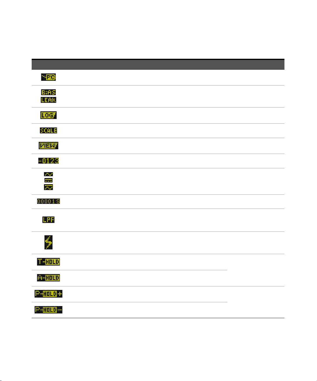
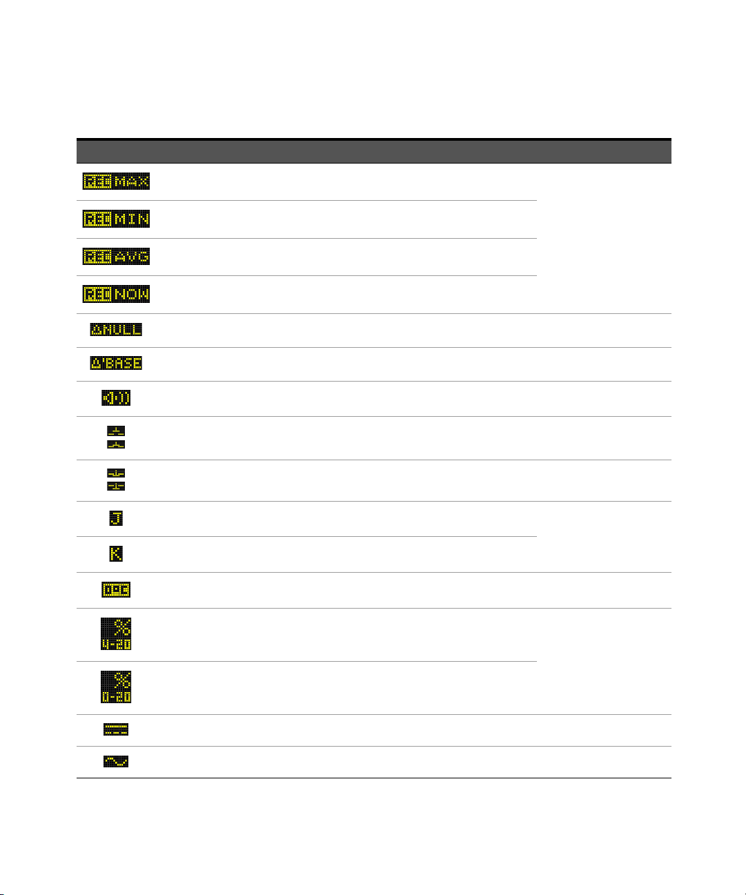
Table 1-6 General annunciators
Legend Description Learn more on:
Remote control enabled page 30
Bias voltage or leakage current indication for Smart Ω measurements page 76
Data logging in progress page 115
Scale transfer enabled page 108
View mode for reviewing previously logged data page 120
Secondary measurement display -
AC, DC, and AC+DC indication for secondary display
Elapsed time for Peak and Recording mode page 112 and page 115
Low-pass filter enabled for AC measurement
Filter enabled for DC measurement
Hazardous voltage sign for measuring voltage ≥30 V or overload page 28
Trigger hold enabled
Auto hold enabled
Peak hold (maximum value) enabled
Peak hold (minimum value) enabled
page 64, page 67, and
page 100
page 57
page 61
page 114
page 112
Keysight U1273A/U1273AX User’s Guide 45
Page 46
1Introduction
Tab le 1-6 General annunciators (continued)
Legend Description Learn more on:
Maximum reading shown on primary display
Minimum reading shown on primary display
page 110
Averaged reading shown on primary display
Present reading shown on primary display
Relative (Null) enabled page 106
Relative value when Null is enabled page 106
Audible continuity test selected page 73
Normal open continuity indication page 73
Normal close continuity indication page 73
J-type thermocouple selected
page 88
K-type thermocouple selected
Temperature measurement without ambient compensation selected page 90
4-20 mA % scale mode selected
page 97
0-20 mA % scale mode selected
DC (direct current) page 58 and page 91
AC (alternating current) page 54 and page 91
46 Keysight U1273A/U1273AX User’s Guide
Page 47
Introduction 1
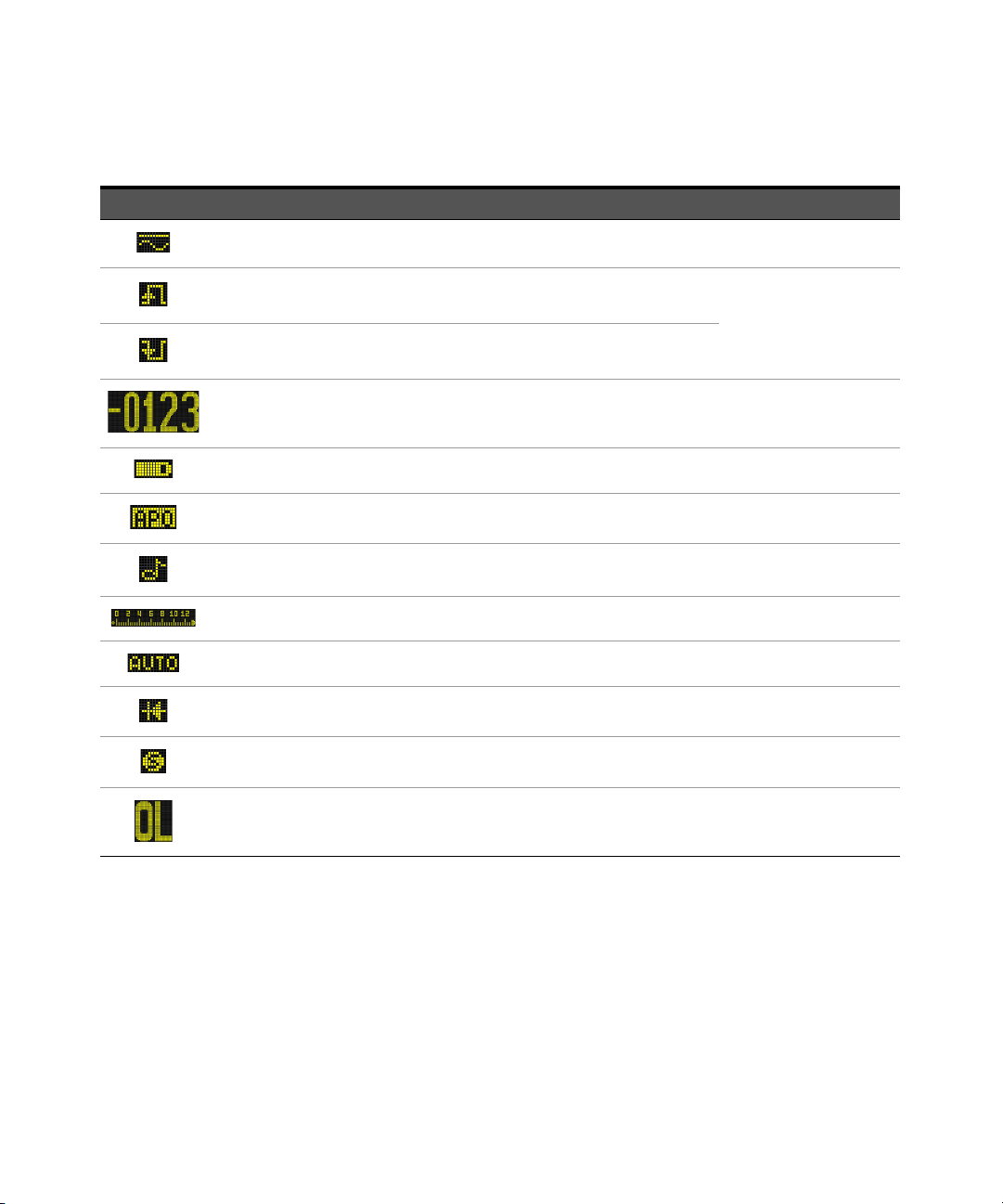
Table 1-6 General annunciators (continued)
Legend Description Learn more on:
AC+DC page 61
– Capacitor is charging (during capacitance measurement)
– Positive slope for pulse width (ms) and duty cycle (%) measurements
– Capacitor is discharging (during capacitance measurement)
– Negative slope for pulse width (ms) and duty cycle (%) measurements
Primary measurement display -
Battery capacity indication page 23
APO (Auto Power-Off) enabled page 26
Tone enabled -
Analog bar graph page 49
page 58 and page 100
Auto-ranging enabled or Auto-diode enabled page 27
Diode test selected page 79
Smooth mode enabled page 32 and page 144
Overload (the reading exceeds the display range) -
Keysight U1273A/U1273AX User’s Guide 47
Page 48

1Introduction
Measurement units
The available signs and notations for each measurement function in your
multimeter are described in Table 1 -7. The units listed below are applicable to the
primary display and secondary display measurements of your multimeter.
Tab le 1-7 Measurement units display
Sign/Notation Description
M Mega 1E+06 (1000000)
k kilo 1E+03 (1000)
n nano 1E–09 (0.000000001)
μ micro 1E–06 (0.000001)
m milli 1E–03 (0.001)
dBm Decibel unit relative to 1 mW
dBV Decibel unit relative to 1 V
mV, V Voltage, units for voltage measurement
A, mA, μA Ampere, units for current measurement
nF, μF, mF Farad, units for capacitance measurement
Ω, kΩ, MΩ Ohm, units for resistance measurement
MHz, kHz, Hz Hertz, units for frequency measurement
ms Millisecond, unit for pulse width measurement
% Percent, unit for duty cycle measurement
°C Degree Celsius, unit for temperature measurement
°F Degree Fahrenheit, unit for temperature measurement
s Seconds, unit for Peak and Recording mode elapsed time
48 Keysight U1273A/U1273AX User’s Guide
Page 49

Analog bar graph
The analog bar emulates the needle on an analog multimeter, without displaying
the overshoot. When measuring peak or null adjustments and viewing
fast-changing inputs, the bar graph provides a useful indication because it has a
faster updating rate
For frequency, duty cycle, pulse width, 4-20 mA % scale, 0-20 mA % scale, dBm,
dBV, and temperature measurements, the bar graph does not represent the
primary display value.
For example, when frequency, duty cycle, or pulse width is displayed on the
primary display during voltage or current measurement, the bar graph represents
the voltage or current value (not the frequency, duty cycle, or pulse width value).
Another example is when 4-20 mA % scale or 0-20 mA % scale is displayed on the
primary display, the bar graph represents the current value and not the
percentage value.
The “+” or “–” sign indicates whether the measured or calculated value is positive
or negative. Each segment represents 1000 or 500 counts depending on the
range indicated on the peak bar graph.
Table 1-8 Analog bar graph display
[1]
Introduction 1
to cater for fast-response applications.
Range
Counts/
Segments
500
1000
Used for the function
, ,
, , ,
An unstable bar graph and unmatched primary display when measuring DC
voltage usually means the presence of AC voltages in the circuit.
[1] The analog bar graph measurement rate is approximately 50 times/second for DC voltage, current,
and resistance measurements.
Keysight U1273A/U1273AX User’s Guide 49
Page 50

1Introduction
Input terminals
The terminal connections for the different measurement functions of your
multimeter are described in the table below. Observe the rotary switch position of
your multimeter before connecting the test leads to the connector terminals.
Figure 1-15 Connector terminals
50 Keysight U1273A/U1273AX User’s Guide
Page 51

Table 1-9 Terminal connections for different measuring functions
Z
LOW
Smart
Auto
Rotary switch position Input terminals Overload protection
1000 VRMS for short circuit <0.3 A
Introduction 1
RMS
1000 V
11 A/1000 V, fast-acting fuse
440 mA/1000 V, fast-acting fuse
Keysight U1273A/U1273AX User’s Guide 51
Page 52

1Introduction
WARNING
Cleaning Your Multimeter
To avoid electrical shock or damage to the multimeter, ensure that the
insides of the casing stay dry at all times.
Dirt or moisture in the terminals can distort readings. Follow the steps below to
clean your multimeter.
1 Turn the multimeter off, and remove the test leads.
2 Turn the multimeter over, and shake out any dirt that may have accumulated
in the terminals.
Wipe the case with a damp cloth and mild detergent — do not use abrasives or
solvents. Wipe the contacts in each terminal with a clean swab dipped in alcohol.
52 Keysight U1273A/U1273AX User’s Guide
Page 53

Keysight U1273A/U1273AX Handheld Digital Multimeter
User’s Guide
2 Making Measurements
Crest Factor 54
Measuring AC Voltage 55
Measuring DC Voltage 58
Measuring AC and DC Signals 62
Using Z
Measuring Resistance 69
Testing for Continuity 73
Using Smart Ω for Resistance Measurements 76
Testing Diodes 79
Using Auto-diode for Diode Tests 83
Measuring Capacitance 85
Measuring Temperature 87
Measuring AC or DC Current 91
Measuring Frequency 100
for Voltage Measurements 67
LOW
The following sections describe how to take measurements with your multimeter.
53
Page 54

2 Making Measurements
Crest factor
Peak value
True RMS value
----------------------------------=
WARNING
Crest Factor
The crest factor may be determined by using this formula:
You may refer to “Capturing Peak Values (Peak)” on page 112 on how to obtain
the peak values.
The crest factor may be up to 3.0 at full-scale except for the 1000 V range where
it is 1.5 at full scale, as explained in the table below:
Voltage range Crest factor
30 mV 3 +/– 90 mV
300 mV 3 +/– 900 mV
3 V 3 +/– 9 V
30 V 3 +/– 90 V
300 V 3 +/– 900 V
1000 V 1.5 +/– 1500 V
Maximum input (V
peak
)
Exceeding the crest factor limit may resul t in an incorrect or a lower reading.
Do not exceed the crest factor limit to avoid instrument damage and the risk
of electric shock.
54 Keysight U1273A/U1273AX User’s Guide
Page 55

Making Measurements 2
NOTE
S
h
i
f
t
V
i
e
w
E
s
c
Measuring AC Voltage
Set up your multimeter to measure AC voltage as shown in Figure 2-2. Probe the
test points, and read the display.
Table 2-1 Rotary switch positions allowing AC voltage measurements
Legend Defaul t function
AC V AC V with LPF
AC mV AC mV with LPF
DC V
DC mV
AC voltage measurements measured with this multimeter are returned as true
RMS (root mean square) readings. These readings are accurate for sinusoidal
waves and other waveforms with no DC offset, such as square waves, triangle
waves, and staircase waves.
Function when is pressed
Cycles between
–AC V,
– AC+DC V, or
–DC V
Cycles between
–AC mV,
– AC+DC mV, or
–DC mV
Figure 2-1 AC vol tage display
Keysight U1273A/U1273AX User’s Guide 55
Page 56

2 Making Measurements
NOTE
Exit
Dual
H
z
%
m
s
L
o
g
AC
– For measuring AC voltage signals with DC offset, refer to the Using the Filter
Function for DC measurements section later in this manual.
– Press to cycle through the available dual display combinations. See
Appendix B, “Dual Display Combinations Using the Dual Key,” starting on
page 155 to learn more.
– Press to measure the frequency of the AC voltage source. See
“Measuring Frequency” on page 100 to learn more.
Figure 2-2 Measuring AC voltage
56 Keysight U1273A/U1273AX User’s Guide
Page 57

Making Measurements 2
S
h
i
f
t
V
i
e
w
E
s
c
S
h
i
f
t
V
i
e
w
E
s
c
WARNING
Using the LPF (Low Pass Filter) function for AC measurements
Your multimeter is equipped with an AC low-pass filter to help reduce unwanted
electronic noise when measuring AC voltage or AC frequency.
Table 2-2 Rotary switch positions allowing AC voltage measurements with LPF
Legend Defaul t function
AC V AC V with LPF
AC mV AC mV with LPF
Set up your multimeter to measure AC voltage as shown in Figure 2-2. Press
to activate the LPF option. Your multimeter continues measuring in the
chosen AC mode, but now the signal diverts through a filter that blocks unwanted
voltages above 1 kHz. Probe the test points, and read the display.
Figure 2-3 AC voltage with LPF d isplay
– To avoid possible electric shock or personal injury, do not use the Low
Pass Filter option to verify the presence of hazardous AC voltages. AC
voltage values greater than what are indicated may be present when the
Low Pass Filter is enabled.
Function when is pressed
– First, make an AC voltage measurement with the filter OFF to detect the
possible presence of hazardous voltages. Then, select the filter function if
required for measurement stability and response speed.
Keysight U1273A/U1273AX User’s Guide 57
Page 58

2 Making Measurements
NOTE
S
h
i
f
t
V
i
e
w
E
s
c
The low-pass filter can improve measurement performance on composite sine
waves that are typically generated by inverters and variable frequency motor
drives.
Measuring DC Voltage
Set up your multimeter to measure DC voltage as shown in Figure 2-5. Probe the
test points, and read the display.
Tab le 2-3 Rotary switch positions allowing DC voltage measurements
Legend Default function
DC V
DC mV
This multimeter displays DC voltage values as well as their polarity. Negative
DC voltages will return a negative sign on the left of the display.
Function when is pressed
Cycles between
–AC V,
– AC+DC V, or
–DC V
Cycles between
–AC mV,
– AC+DC mV, or
–DC mV
Figure 2-4 DC voltage d isplay
58 Keysight U1273A/U1273AX User’s Guide
Page 59

Making Measurements 2
NOTE
CAUTION
Exit
Dual
H
z
%
m
s
L
o
g
– For firmware version 1.64 and below, the Filter function is switched off by
default. Customers are advised to update their products to the latest
firmware version to take advantage of the latest safety features and
measurement improvements.
– Press to cycle through the available dual display combinations. See
Appendix B, “Dual Display Combinations Using the Dual Key,” starting on
page 155 to learn more.
– Press to measure the frequency of the DC voltage source. See
“Measuring Frequency” on page 100 to learn more.
– For measuring AC voltage signals with a DC offset, refer to “Measuring AC
and DC Signals” on page 62.
– For measuring DC voltage from a mixed signal in DC measurement mode,
ensure that the Filter is enabled (Refer to “Enabling the filter” on page 146).
– To avoid possible electric shock or personal injury, enable the Filter(LPF) to
verify the presence of hazardous DC voltages. Displayed DC voltage values
can be influenced by high frequency AC components and must be filtered to
assure an accurate reading.
Keysight U1273A/U1273AX User’s Guide 59
Page 60
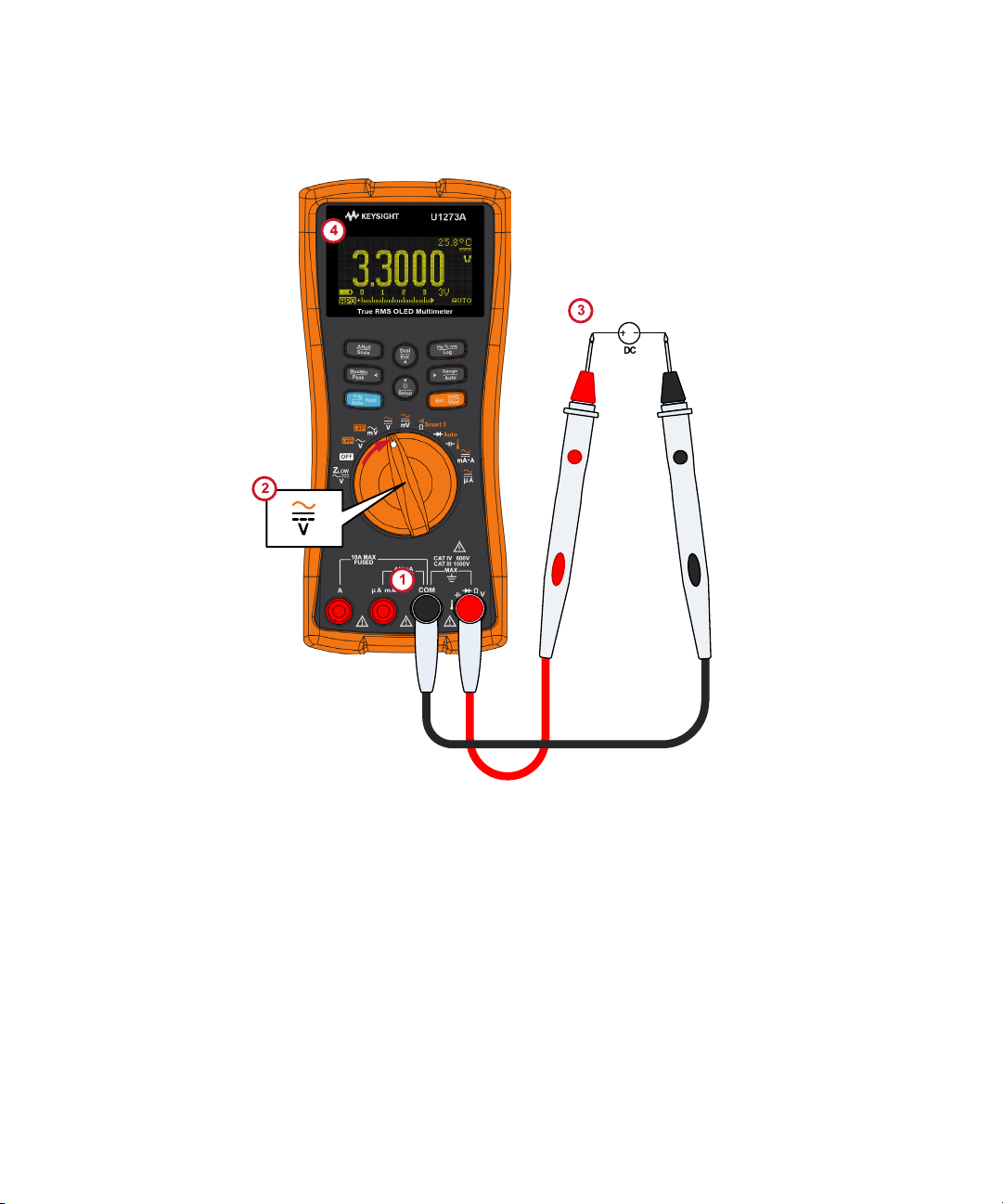
2 Making Measurements
Figure 2-5 Measuring DC voltage
60 Keysight U1273A/U1273AX User’s Guide
Page 61
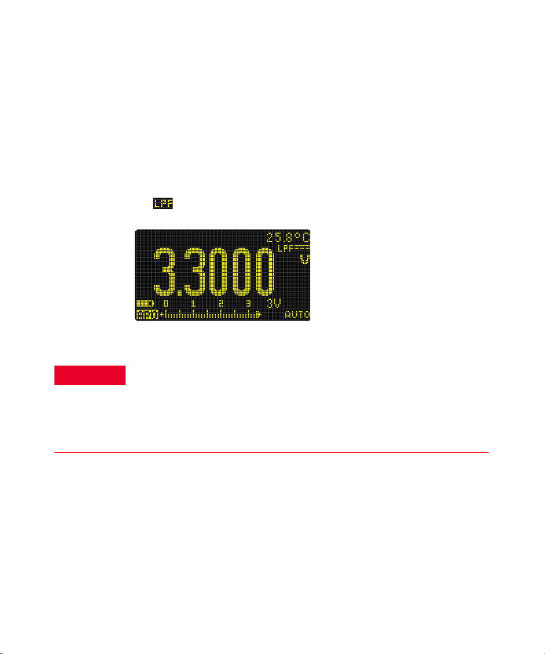
Using the Filter Function for DC measurements
WARNING
Turn on the Filter Function when measuring DC voltage and/or current from a
mixed signal (AC+DC components) in the DC voltage measurement mode. See
“Enabling the filter” on page 146 for more information.
The Filter Function blocks and attenuates AC signals to help you read the DC
measurement from a mixed signal. For instance, a DC offset with an AC voltage
signal presence (for example, AC 100 V/220 V applied to the 3 V range).
The will appear if the Filter is enabled in the multimeter’s Setup.
Figure 2-6 Filter for DC vol tage measurements
Making Measurements 2
Keysight U1273A/U1273AX User’s Guide 61
– To avoid possible electric shock or personal injury, enable the Filter(LPF)
to verify the presence of hazardous DC voltages. Displayed DC voltage
values can be influenced by high frequency AC components and must be
filtered to assure an accurate reading.
– Do not enable any of the dual display options when performing
measurements to verify the presence of hazardous DC voltages.
Page 62

2 Making Measurements
S
h
i
f
t
V
i
e
w
E
s
c
S
h
i
f
t
V
i
e
w
E
s
c
Measuring AC and DC Signals
Your multimeter is capable of displaying both AC and DC signal components,
voltage or current, as two separate readings or one AC+DC (RMS) value
combined.
Tab le 2-4 Rotary switch positions allowing AC+DC signal measurements
Legend Default function
DC V
DC mV
DC A (or mA)
DC µA
Set up your multimeter according to your desired measurement (voltage or
current measurement). Press the key twice to cycle the measurement
function to the AC+DC option. Probe the test points, and read the display.
Function when is pressed
Cycles between
–AC V,
– AC+DC V, or
–DC V
Cycles between
–AC mV,
– AC+DC mV, or
–DC mV
Cycles between
– AC A (or mA),
–AC+DC A (or mA), or
–DC A (or mA)
Cycles between
–AC µA,
– AC+DC µA, or
–DC µA
62 Keysight U1273A/U1273AX User’s Guide
Page 63

Figure 2-7 AC+DC voltage display
NOTE
Exit
Dual
H
z
%
m
s
L
o
g
Making Measurements 2
Figure 2-8 AC+DC current display
– For better accuracy when measuring the DC offset of an AC voltage, measure
the AC voltage first. Note the AC voltage range, then manually select a DC
voltage range equal to or higher than the AC range. This procedure improves
the accuracy of the DC measurement by ensuring that the input protection
circuits are not activated.
– Press to cycle through the available dual display combinations. See
Appendix B, “Dual Display Combinations Using the Dual Key,” starting on
page 155 to learn more.
– Press to measure the frequency of the AC+DC voltage source. See
“Measuring Frequency” on page 100 to learn more.
Keysight U1273A/U1273AX User’s Guide 63
Page 64

2 Making Measurements
S
h
i
f
t
V
i
e
w
E
s
c
Exit
Dual
Using the LPF (Low Pass Filter) Function for AC+DC measurements
Your multimeter is equipped with an AC low pass filter to help reduce unwanted
electronic noise when measuring a mixed signal.
1 Enable the LPF (You may refer to “Enabling the filter” on page 146)
2 Rotate the multimeter’s rotary switch to / .
3 Press to activate the low pass filter function ( ). Your multimeter
continues measuring in the AC+DC mode, but now the signal diverts through a
filter that blocks unwanted voltages above 1 kHz
Figure 2-9 Low Pass Filter(LPF) for AC+DC voltage measurements
Making dB Measurements
Your multimeter is capable of displaying voltage as a dB value, either relative to
1 milliwatt (dBm) or a reference voltage of 1 volt (dBV).
Displaying dBm values
To set the multimeter to display voltage values in dBm, first set up your
multimeter to measure voltage as shown in Figure 2-2 or Figure 2-5. Probe the
test points, and read the display. Then, press until the voltage measurements
are displayed as a dBm value.
64 Keysight U1273A/U1273AX User’s Guide
Page 65

Table 2-5 Rotary switch positions allowing dBm measurements
NOTE
S
h
i
f
t
V
i
e
w
E
s
c
Exit
Dual
Making Measurements 2
Legend Defaul t function
AC V AC V with LPF
AC mV AC mV with LPF
DC V
DC mV
A dBm measurement must use a reference impedance (resistance) to calculate a
dB value based on 1 milliwatt. The reference impedance is set to 50 Ω by
default. To select another reference value, see the “Changing the custom dBm
reference impedance” on page 134.
Function when is pressed
Cycles between
–AC V,
– AC+DC V, or
–DC V
Cycles between
–AC mV,
–AC+DC mV, or
–DC mV
Figure 2-10 dBm display
Press for more than 1 second to exit the dBm function.
Keysight U1273A/U1273AX User’s Guide 65
Page 66

2 Making Measurements
NOTE
Exit
Dual
NOTE
S
h
i
f
t
V
i
e
w
E
s
c
Displaying dBV values
To set the multimeter to display voltage values in dBV, first change the dB
(decibel) display from dBm to dBV in the setup menu. See “Changing the decibel
display” on page 133 to learn more.
This change is permanent. To set the multimeter to display voltage values in
dBm again, you will need to change the dB display from dBV back to dBm in the
setup menu.
Next, set up your multimeter to measure voltage as shown in Figure 2-2 or
Figure 2-5. Probe the test points, and read the display. Then, press until the
voltage measurements are displayed as a dBV value.
Tab le 2-6 Rotary switch positions allowing dBV measurements
Legend Default function
AC V AC V with LPF
AC mV AC mV with LPF
DC V
DC mV
A dBV measurement uses a 1 volt reference voltage to compare the present
measurement against a stored relative value. The difference between the two AC
signals is d isplayed as a dBV value. The reference impedance setting is not part
of a dBV measurement.
Function when is pressed
Cycles between
–AC V,
– AC+DC V, or
–DC V
Cycles between
–AC mV,
– AC+DC mV, or
–DC mV
66 Keysight U1273A/U1273AX User’s Guide
Page 67

Making Measurements 2
Exit
Dual
CAUTION
S
h
i
f
t
V
i
e
w
E
s
c
ZLOW
Figure 2-11 dBV display
Press for more than 1 second to exit the dBV function.
Using Z
for Voltage Measurements
LOW
Do not use the Z
function to measure voltages in circuits that could be
LOW
damaged by this function’s low impedance (≈2 kΩ).
The Z
function in your multimeter presents a low impedance across the leads
LOW
to obtain a more accurate measurement.
Table 2-7 Rotary switch positions allowing Z
Legend Defaul t function
Z
(AC/DC) V
LOW
To set up your multimeter to make a Z
measurement, first set up your multimeter to measure voltage as shown in
Figure 2-2 or Figure 2-5. Probe the test points, and read the display.
measurements
LOW
Function when is pressed
-
(low input impedance) voltage
LOW
Keysight U1273A/U1273AX User’s Guide 67
Page 68

2 Making Measurements
NOTE
NOTE
Exit
Dual
NOTE
The AC voltage measurement is shown in the primary display and the DC
voltage measurement is shown in the secondary display. Press to exchange
the AC and DC voltage indication on the primary and secondary displays.
Use the Z
(low input impedance) function to remove ghost or induced
LOW
voltages from your measurements
Ghost voltages are voltages present on a circuit that should not be energized.
Ghost voltages can be caused by capacitive coupling between energized wiring
and adjacent unused wiring. The Z
your measurements by dissipating the coupling voltage. Use the Z
function can remove ghost voltages from
LOW
function
LOW
to reduce the possibility of false readings in areas where the presence of ghost
voltages are suspected.
Figure 2-12 Z
During Z
measurements, autoranging is disabled and the multimeter’s range
LOW
LOW
display
is set to 1000 V in the manual ranging mode. The analog bar graph represents
the AC+DC voltage value combined.
68 Keysight U1273A/U1273AX User’s Guide
Page 69

Making Measurements 2
NOTE
CAUTION
S
h
i
f
t
V
i
e
w
E
s
c
Smart
Use Z
to test a battery’s health
LOW
Aside from reading a battery’s voltage level using the DC voltage measurement
function, you can also use the Z
function to test a battery’s health.
LOW
If you detect that the measured battery’s voltage shown in the Z
declining gradually, this means that the capacity of the battery-under-test is not
enough to support regular functions. Use this simple and quick test to determine
if a battery has enough voltage capacity to support regular activities.
Prolonged used of the Z
function will consume the capacity of the
LOW
battery-under-test.
Measuring Resistance
Set up your multimeter to measure resistance as shown in Figure 2-14. Probe the
test points, and read the display.
Table 2-8 Rotary switch position allowing resistance measurements
Legend Defaul t function
Resistance measurement (Ω)
Function when is pressed
Cycles between
–Continuity test ( ),
– Smart Ω measurement, or
– Resistance measurement (Ω)
function is
LOW
To avoid possible damage to your multimeter or to the equipment under
test, disconnect the circuit power and discharge all high-voltage capacitors
before measuring resistance.
Keysight U1273A/U1273AX User’s Guide 69
Page 70

2 Making Measurements
NOTE
Resistance (opposition to the current flow) is measured by sending a small
current out through the test leads to the circuit under test. Because this current
flows through all possible paths between the leads, the resistance reading
represents the total resistance of all paths between the leads. Resistance is
measured in ohms (Ω).
Figure 2-13 Resistance display
70 Keysight U1273A/U1273AX User’s Guide
Page 71

Making Measurements 2
Figure 2-14 Measuring resistance
Keysight U1273A/U1273AX User’s Guide 71
Page 72

2 Making Measurements
NOTE
S
c
a
l
e
N
u
l
l
A
u
t
o
R
a
n
g
e
A
u
t
o
R
a
n
g
e
Keep the following in mind when measuring resistance.
– The test leads can add 0.1 Ω to 0.2 Ω of error to resistance measurements. To
test the leads, touch the probe tips together and read the resistance of the
leads. To remove lead resistance from the measurement, hold the test lead
tips together and press . Now the resistance at the probe tips will be
subtracted from all future display readings.
– Because the multimeter’s test current flows through all possible paths
between the probe tips, the measured value of a resistor in a circuit is often
different from the resistor’s rated value.
– The resistance function can produce enough voltage to forward-bias silicon
diode or transistor junctions, causing them to conduct. If this is suspected,
press to apply a lower current in the next higher range.
Measuring conductance
Conductance is the reciprocal of resistance. High values of conductance
correspond to low values of resistance. Conductance is measured in Siemens (S).
The 300 nS range measures conductance in nano-Siemens (1 nS = 0.000000001
Siemens). Because small conductance values correspond to extremely high
resistance values, the nS range allows you to easily calculate and determine the
resistance of components up to 100 GΩ (0.01 nS resolution)
To measure conductance, set up your multimeter to measure resistance as shown
in Figure 2-14. Press until the conductance measurement is selected (nS
unit shown). Probe the test points, and read the display.
High-resistance readings are susceptible to electrical noise. Use averaging to
smooth out most of the noisy readings. Refer to “Capturing Maximum and
Minimum Values (MaxMin)” on page 110.
72 Keysight U1273A/U1273AX User’s Guide
Page 73

Testing for Continuity
CAUTION
NOTE
S
h
i
f
t
V
i
e
w
E
s
c
Smart
Set up your multimeter to test for continuity as shown in Figure 2-16. Probe the
test points, and read the display.
Table 2-9 Rotary switch position allowing continuity tests
Making Measurements 2
Legend Defaul t function
Function when is pressed
Cycles between
Resistance measurement (Ω)
–Continuity test ( ),
– Smart Ω measurement, or
– Resistance measurement (Ω)
To avoid possible damage to your multimeter or to the equipment under
test, disconnect the circuit power and discharge all high-voltage capacitors
before testing for continuity.
Continuity is the presence of a complete path for current flow. The continuity
test features a beeper that sounds as long as a circuit is complete, if normal
open is selected (or broken, if normal closed is selected). The audible alert
allows you to perform quick continuity tests without having to watch the display.
In continuity, a short means a measured value is less that the threshold resistance
values listed in Table 2-10.
Table 2-10 Threshold resistance values
Measuring range Threshold resistance
30.000 Ω <25 ± 10 Ω
300.00 Ω <25 ±10 Ω
3.0000 kΩ <250 ±100 Ω
30.000 kΩ <2.5 ± 1 kΩ
300.00 kΩ <25 ± 10 kΩ
Keysight U1273A/U1273AX User’s Guide 73
Page 74

2 Making Measurements
Exit
Dual
Press to enable the
continuity test function.
Press to switch
between the normal open
and normal closed states.
S
h
i
f
t
V
i
e
w
E
s
c
Exit
Dual
Start to capture
Circuit complete.Short detected, beeper
sounds.
Open detected, beeper
sounds.
Circuit open.
Table 2-10 Threshold resistance values (continued)
Measuring range Threshold resistance
3.0000 MΩ <120 ± 60 kΩ
30.000 MΩ <120 ± 60 kΩ
300.00 MΩ <120 ± 60 kΩ
The beeper will sound as a continuity indication. Press to switch between
normal open ( ) and normal close ( ) contacts.
– Normal open: Circuit is normally open, the beeper will sound when a short is
detected.
– Normal closed: Circuit is normally closed, the beeper will sound when an open
is detected.
Figure 2-15 Continuity operation
74 Keysight U1273A/U1273AX User’s Guide
Page 75

Making Measurements 2
NOTE
– The continuity function detects intermittent shorts and opens lasting as short
as 1 ms. A brief short or open causes the multimeter to emit a short beep.
– You can enable or disable the audible alert via the multimeter’s setup. See
“Changing the beep frequency” on page 138 for more information on the
audible alert option.
Figure 2-16 Testing for continuity
Keysight U1273A/U1273AX User’s Guide 75
Page 76
2 Making Measurements
NOTE
S
h
i
f
t
V
i
e
w
E
s
c
Smart
Exit
Dual
NOTE
Using Smart Ω for Resistance Measurements
To use the Smart Ω function, set up your multimeter to test for resistance as
shown in Figure 2-17. Probe the test points, and read the display.
Table 2-11 Rotary switch position allowing Smart Ω measurements
Legend Default function
Resistance measurement (Ω)
– Smart Ω (offset compensation) removes unexpected DC voltages within the
instrument, at the input or at the circuit being measured, which will add to
resistance measurement errors. The bias voltage or leakage current is shown
on the secondary display.
– Using the offset compensation method, the multimeter takes the difference
between two resistance measurements when two different test currents are
applied to determine if there are any offset voltages in the input circuitry. The
resultant displayed measurement corrects this offset, giving a more accurate
resistance measurement.
The resistance measurement and the bias voltage measurement is shown in the
primary and secondary displays respectively.
Press to switch between the leakage current (LEAk) or bias voltage (BiAS)
display.
Function when is pressed
Cycles between
– Continuity test ( ),
– Smart Ω measurement, or
– Resistance measurement (Ω)
–The Smart Ω is applicable for the 30 Ω, 300 Ω, 3 kΩ, 30 kΩ, and 300 kΩ
resistance range only. The maximum correctable offset/bias voltage is
+50 mV/–30 mV for the 30 Ω range and +1.0 V/–0.2 V for the 300 Ω,
3 kΩ, 30 kΩ, and 300 kΩ ranges.
– If the DC voltage on the resistor is over the maximum correctable offset/bias
voltage, OL is shown on the secondary display.
76 Keysight U1273A/U1273AX User’s Guide
Page 77

Figure 2-17 Smart Ω (with bias voltage) display
Making Measurements 2
Figure 2-18 Smart Ω (with leakage current) display
Use Smart Ω to measure the resistance of a thermocouple sensor
It is useful to measure the resistance of a thermocouple temperature sensor. The
thermovoltage is proportional to the temperature and the impact of the resistance
measurement. Using the Smart Ω function will help you achieve precise readings
regardless of the temperature.
Use Smart Ω to measure leakage current
Use the Smart Ω function to measure leakage current or reverse current for
junction diodes. Such leakage currents are negligible and are usually measured in
units of μA or nA. Instead of having to source a high-precision multimeter with a
1 nA or 0.1 nA accuracy or a precision shunt, you can measure the leakage current
using the Smart Ω function with just a resistor from 100 kΩ to 300 kΩ.
Keysight U1273A/U1273AX User’s Guide 77
Page 78

2 Making Measurements
Figure 2-19 Measuring leakage current
78 Keysight U1273A/U1273AX User’s Guide
Page 79

Testing Diodes
CAUTION
NOTE
S
h
i
f
t
V
i
e
w
E
s
c
Auto
Set up your multimeter to test diodes as shown in Figure 2-22. Probe the test
points, and read the display.
Table 2-12 Rotary switch position allowing d iode tests
Making Measurements 2
Legend Defaul t function
Diode test Auto-diode test
To avoid possible damage to your multimeter or to the equipment under
test, disconnect the circuit power and discharge all high-voltage capacitors
before testing diodes.
– Use the diode test to check diodes, transistors, silicon controlled rectifiers
(SCRs), and other semiconductor devices. A good d iode allows current to
flow in one direction only.
– This test sends a current through a semiconductor junction, and then
measures the junction’s voltage drop. A typical junction drops 0.3 V to 0.8 V.
– Connect the red test lead to the positive terminal (anode) of the diode and
the black test lead to the negative terminal (cathode). The cathode of a diode
is indicated with a band.
Function when is pressed
Figure 2-20 Diode display
Keysight U1273A/U1273AX User’s Guide 79
Page 80

2 Making Measurements
NOTE
– Your multimeter can display diode forward-bias of up to approximately 3.1 V.
The forward-bias of a typical diode is within the range of 0.3 V to 0.8 V;
however, the reading can vary depending on the resistance of other
pathways between the probe tips.
– If the beeper is enabled during diode test, the multimeter will beep briefly for
a normal junction and sound continuously for a shorted junction, below
0.050 V. See “Changing the beep frequency” on page 138 to disable the
beeper.
Reverse the probes (as shown in Figure 2-23) and measure the voltage across the
diode again. Assess the diode according to the following guidelines:
– A diode is considered good if the multimeter displays OL in reverse-bias
mode.
– A diode is considered shorted if the multimeter displays approximately 0 V
in both forward- and reverse-bias modes, and the multimeter beeps
continuously.
– A diode is considered open if the multimeter displays OL in both forward-
and reverse-bias modes.
Figure 2-21 Open diode display
80 Keysight U1273A/U1273AX User’s Guide
Page 81
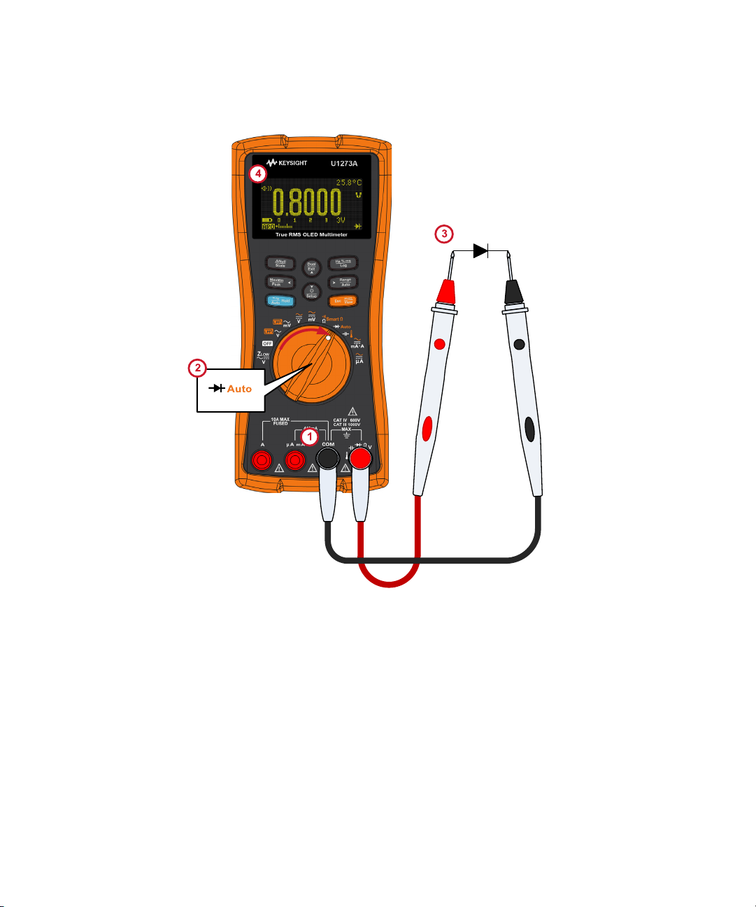
Making Measurements 2
Figure 2-22 Testing a forward-bias diode
Keysight U1273A/U1273AX User’s Guide 81
Page 82

2 Making Measurements
Figure 2-23 Testing a reverse-bias diode
82 Keysight U1273A/U1273AX User’s Guide
Page 83

Using Auto-diode for Diode Tests
NOTE
S
h
i
f
t
V
i
e
w
E
s
c
Auto
NOTE
Set up your multimeter to test diodes as shown in Figure 2-22. Probe the test
points, and read the display.
Table 2-13 Rotary switch position allowing auto-d iode tests
Making Measurements 2
Legend Defaul t function
Diode test Auto-diode test
The auto-diode function will help you test both forward- and reverse-bias
directions simultaneously. You do not need to change the measuring direction to
identify the diode’s status.
Table 2-14 Auto-d iode voltage thresholds
Forward voltage Reverse voltage Diode status
Primary display Secondary d isplay Good No Good
OL or <0.3 V or >0.8 V –OL or >–0.3 V or <–0.8 V ✘
Within 0.3 V to 0.8 V –OL ✔
OL Within –0.3 V to –0.8 V ✔
The open condition will not be alerted as OL on both directions if the auto-diode
function is used.
Function when is pressed
The primary display shows the forward-bias voltage value. The reverse-bias
voltage value is shown in the secondary display.
– GOOD is shown briefly (along with a single beep) on the secondary display if
the diode is in a good condition.
– NGOOD is shown briefly (along with two beeps) if the diode is out of the
thresholds.
Keysight U1273A/U1273AX User’s Guide 83
Page 84

2 Making Measurements
Figure 2-24 Auto-diode display (GOOD status)
Figure 2-25 Auto-diode display (NGOOD status)
84 Keysight U1273A/U1273AX User’s Guide
Page 85

Making Measurements 2
CAUTION
NOTE
S
h
i
f
t
V
i
e
w
E
s
c
NOTE
S
c
a
l
e
N
u
l
l
Measuring Capacitance
Set up your multimeter to measure capacitance as shown in Figure 2-27. Probe
the test points, and read the display.
Table 2-15 Rotary switch position allowing capacitance measurements
Legend Defaul t function
Capacitance measurement Temperature measurement
To avoid possible damage to the multimeter or to the equipment under test,
disconnect circuit power and discharge all high-voltage capacitors before
measuring capacitance. Use the DC voltage function to confirm that the
capacitor is fully discharged.
– The multimeter measures capacitance by charging the capacitor with a
known current for a known period of time, measuring the resulting voltage,
and then calculating the capacitance.
– is shown on the bottom left of the display when the capacitor is charging,
and is shown when the capacitor is discharging.
Function when is pressed
Figure 2-26 Capacitance display
To improve measurement accuracy of small value capacitors, press with
the test leads open to subtract the residual capacitance of the multimeter and
leads.
Keysight U1273A/U1273AX User’s Guide 85
Page 86

2 Making Measurements
NOTE
For measuring capacitance values greater than 1000 μF, discharge the capacitor
first, then select a suitable range for measurement. This will speed up the
measurement time and also ensure that the correct capacitance value is
obtained.
Figure 2-27 Measuring capacitance
86 Keysight U1273A/U1273AX User’s Guide
Page 87

Making Measurements 2
WARNING
CAUTION
S
h
i
f
t
V
i
e
w
E
s
c
Measuring Temperature
Do not connect the thermocouple to electrically live circuits. Doing so will
potentially cause fire or electric shock.
Do not bend the thermocouple leads at sharp angles. Repeated bending
over a period of time can break the leads.
The multimeter uses a type-K (default setting) temperature probe for measuring
temperature. To measure temperature, set up your multimeter as shown in
Figure 2-29.
Table 2-16 Rotary switch position allowing temperature measurements
Legend Defaul t function
Capacitance measurement Temperature measurement
Probe the test points, and read the display. The primary display normally shows
temperature or the message OL (open thermocouple). The open thermocouple
message may be due to a broken (open) probe or because no probe is installed
into the input jacks of the multimeter.
Figure 2-28 Temperature display
Function when is pressed
Keysight U1273A/U1273AX User’s Guide 87
Page 88

2 Making Measurements
A
u
t
o
R
a
n
g
e
CAUTION
NOTE
NOTE
Press to change the temperature units between °C or °F (you must first
change the temperature unit to switch between °C and °F or °F and °C). See
“Changing the temperature unit” on page 135 for more information.
The option to change the temperature unit is locked for certain regions.
Always set the temperature unit display per the official requirements and in
compliance with the National laws of your region.
– Shorting the terminal to the COM terminal will display the temperature at
the multimeter’s terminals.
– To change the default thermocouple type from type-K to type-J, see
“Changing the thermocouple type” on page 135 for more information.
The bead-type thermocouple probe is suitable for measuring temperatures from
–40 °C to 204 °C (399 °F) in PTFE-compatible environments. Do not immerse this
thermocouple probe in any liquid. For best results, use a thermocouple probe
designed for each specific application — an immersion probe for liquid or gel,
and an air probe for air measurement.
Observe the following measurement techniques:
– Clean the surface to be measured, and ensure that the probe is securely
touching the surface. Remember to disable the applied power.
– When measuring above ambient temperatures, move the thermocouple
along the surface until you get the highest temperature reading.
– When measuring below ambient temperatures, move the thermocouple
along the surface until you get the lowest temperature reading.
– Place the mul timeter in the operating environment for at least 1 hour as the
multimeter is using a non-compensation transfer adapter with miniature
thermal probe.
For quick measurement, use the compensation to view the temperature
variation of the thermocouple sensor. The compensation assists you in
measuring relative temperature immediately.
88 Keysight U1273A/U1273AX User’s Guide
Page 89

Making Measurements 2
Type-K Thermocouple Probe
Figure 2-29 Measuring surface temperature
Keysight U1273A/U1273AX User’s Guide 89
Page 90

2 Making Measurements
Exit
Dual
S
c
a
l
e
N
u
l
l
Temperature measurement without ambient compensation
If you are working in a constantly varying environment, where ambient
temperatures are not constant, do the following:
1 Press to select compensation. This allows a quick measurement of the
relative temperature.
2 Avoid contact between the thermocouple probe and the surface to be
measured.
3 After a constant reading is obtained, press to set the reading as the
relative reference temperature.
4 Touch the surface to be measured with the thermocouple probe and read the
display.
Figure 2-30 Temperature measurement without ambient compensation
90 Keysight U1273A/U1273AX User’s Guide
Page 91

Making Measurements 2
WARNING
CAUTION
S
h
i
f
t
V
i
e
w
E
s
c
Measuring AC or DC Current
Set up your multimeter to measure AC or DC current as shown in Figure 2-32 and
Figure 2-33. Open the circuit path to be tested. Probe the test points, and read
the display.
Table 2-17 Rotary switch positions allowing current measurements
Legend Defaul t function
DC A (or mA)
DC µA
Never attempt an in-circuit current measurement where the open-circuit
potential to earth is greater than 1000 V. Doing so will cause damage to the
multimeter and possible electric shock or personal injury.
To avoid possible damage to the multimeter or to the equipment under test:
– Check the multimeter’s fuses before measuring current.
– Use the proper terminals, function, and range for your measurement.
– Never place the probes across (in parallel with) any circuit or component
when the leads are plugged into the current terminals.
Function when is pressed
Cycles between
– AC A (or mA),
–AC+DC A (or mA)
– % Scale of 4-20 mA (or 0-20 mA), or
–DC A (or mA)
Cycles between
–AC µA,
– AC+DC µA, or
–DC µA
Keysight U1273A/U1273AX User’s Guide 91
Page 92
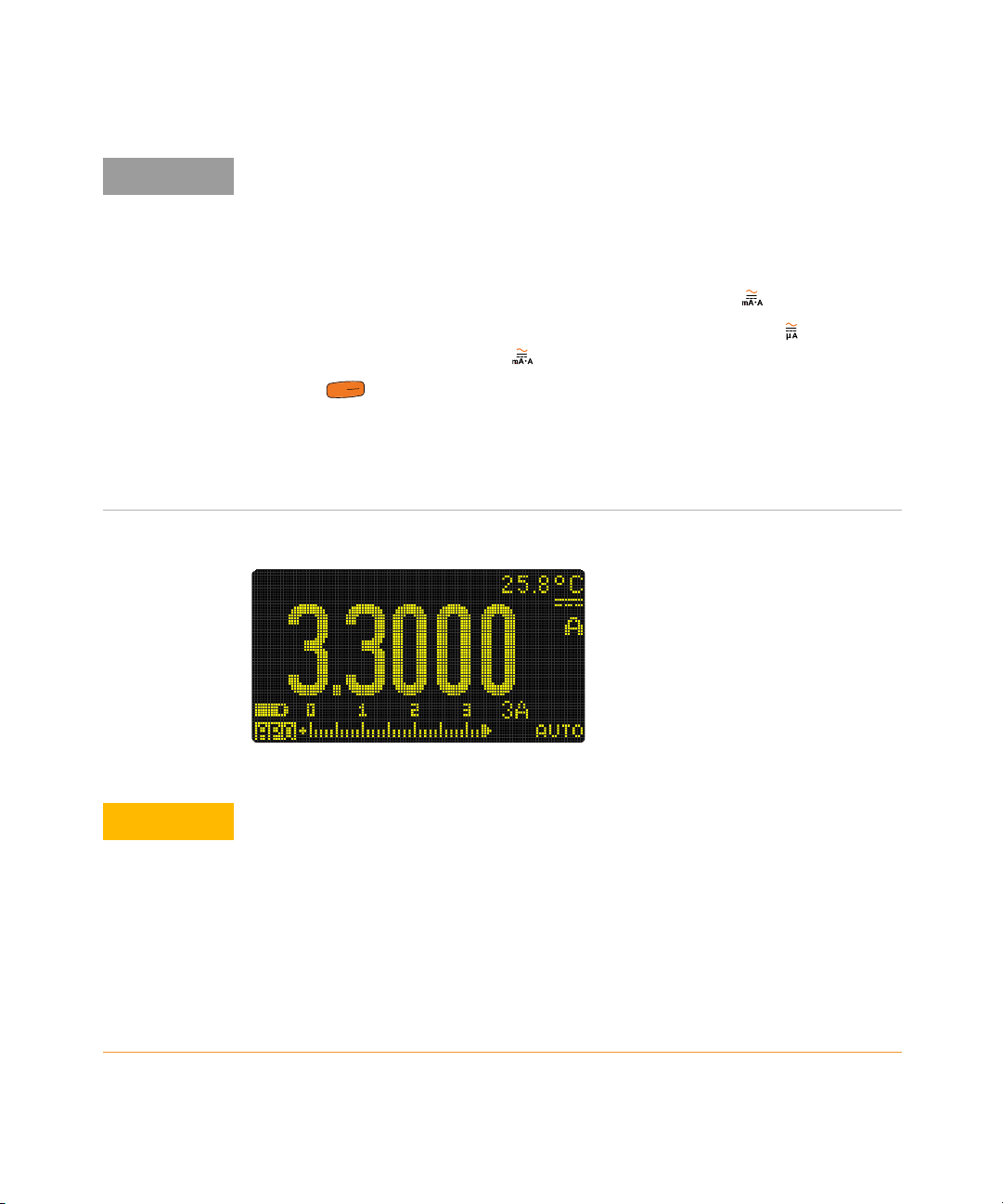
2 Making Measurements
NOTE
S
h
i
f
t
V
i
e
w
E
s
c
CAUTION
– To measure current, you must open the circuit under test, then place the
multimeter in series with the circuit.
– Turn off power to the circuit. Discharge all high-voltage capacitors. Insert the
black test lead into the COM terminal. Insert the red test lead in an input
appropriate for the measurement range.
– If you are using the A terminal, set the rotary switch to .
– If you are using the µA mA terminal, set the rotary switch to for currents
below 5000 μA (5 mA), or for currents above 5000 μA.
– Press to cycle between DC current measurement, AC current
measurement, AC+DC current measurement, or % scale current
measurements.
– Reversing the leads will produce a negative reading, but it will not damage
the multimeter.
Figure 2-31 DC current display
– To avoid blowing the multimeter’s 440 mA fuse, use the µA mA terminal
only if you are sure the current is less than 400 mA. See Figure 2-34 for
test lead connections and function selection. Refer to the Input warning
section for information on the alerts the multimeter uses when leads are
not used correctly for current measurements.
– Placing the probes across (in parallel with) a powered circuit when a lead
is plugged into a current terminal can damage the circuit you are testing
and blow the multimeter's fuse. This happens because the resistance
through the multimeter's current terminals are very low, resulting in a
short circuit.
92 Keysight U1273A/U1273AX User’s Guide
Page 93

Making Measurements 2
CAUTION
NOTE
Exit
Dual
H
z
%
m
s
L
o
g
– For measuring AC current signals with a DC offset, refer to the “Using the
Filter Function for DC measurements” on page 61.
– For measuring DC current from a mixed signal in DC measurement mode,
ensure that the Filter is enabled (Refer to “Enabling the filter” on page 146).
– Press to cycle through the available dual display combinations. See
Appendix B, “Dual Display Combinations Using the Dual Key,” starting on
page 155 to learn more.
– Press to measure the frequency of the AC or DC current source. See
“Measuring Frequency” on page 100 to learn more.
Keysight U1273A/U1273AX User’s Guide 93
Page 94

2 Making Measurements
DC
LOAD
Figure 2-32 Measuring DC current
94 Keysight U1273A/U1273AX User’s Guide
Page 95

Making Measurements 2
Figure 2-33 Measuring AC current
Keysight U1273A/U1273AX User’s Guide 95
Page 96

2 Making Measurements
Figure 2-34 Current measurement setup
96 Keysight U1273A/U1273AX User’s Guide
Page 97

Making Measurements 2
NOTE
S
h
i
f
t
V
i
e
w
E
s
c
% Scale of 4-20 mA or 0-20 mA
To display the current measurement in % scale, position your multimeter’s rotary
switch position to and set up your multimeter to measure DC current by
following the steps listed in the Measuring AC or DC Current section.
Table 2-18 Rotary switch positions allowing current measurements
Legend Defaul t function
DC A (or mA)
– The 4-20 mA current loop output from a transmitter is a type of electrical
signal that is used in a series circuit to provide a robust measurement signal
that is proportional to the applied pressure, temperature, or flow in process
control. The signal is a current loop where 4 mA represents the zero percent
signal and 20 mA represents the 100 percent signal.
– The % scale for 4-20 mA or 0-20 mA in this multimeter is calculated using its
corresponding DC mA measurement. The multimeter will automatically
optimize the best resolution for the selected measurement. Two ranges are
available for the % scale as shown in Table 2-19.
Function when is pressed
Cycles between
– AC A (or mA),
–AC+DC A (or mA)
– % Scale of 4-20 mA (or 0-20 mA), or
–DC A (or mA)
Figure 2-35 4-20 mA % Scale display
Keysight U1273A/U1273AX User’s Guide 97
Page 98

2 Making Measurements
The analog bar graph displays the current measurement value. (In the example
above, 24 mA is represented as 125% in the 4-20 mA % scale.)
Table 2-19 % Scale measurement range
% Scale of 4-20 mA or 0-20 mA DC mA measurement range
999.99%
9999.9%
[a] Applies to both autoranging and manual range selection.
30 mA or 300 mA
You can change the % scale range (4-20 mA or 0-20 mA) by accessing the
multimeter’s setup. See “Changing the % scale range” on page 136 for more
information.
Use the % scale with a pressure transmitter, a valve positioner, or other output
actuators to measure pressure, temperature, flow, pH, or other process variables.
[a]
98 Keysight U1273A/U1273AX User’s Guide
Page 99

Making Measurements 2
Pressure transmitter
Figure 2-36 Measuring DC current using the 0-20 mA % scale
Keysight U1273A/U1273AX User’s Guide 99
Page 100
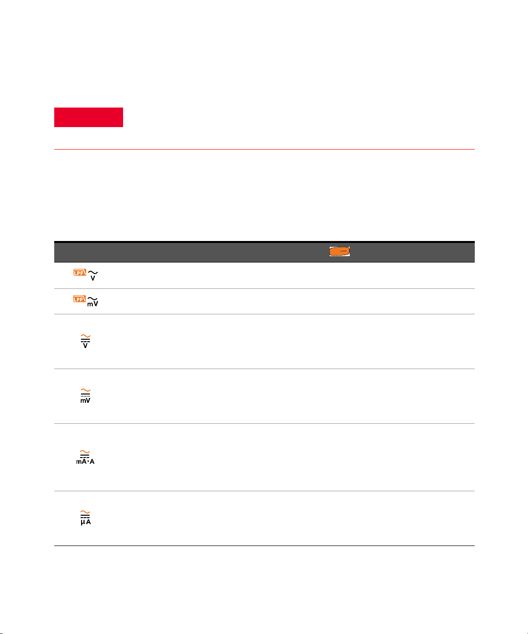
2 Making Measurements
WARNING
S
h
i
f
t
V
i
e
w
E
s
c
Measuring Frequency
Never measure the frequency where the voltage or current level exceeds the
specified range. Manually set the voltage or current range if you want to
measure frequencies below 20 Hz.
Your multimeter allows simultaneous monitoring of real- time voltage or current
with frequency, duty cycle, or pulse width measurements. Ta ble 2- 20 highlights
the functions allowing frequency measurements in your multimeter.
Table 2-20 Rotary switch positions allowing frequency measurements
Legend Default function
AC V AC V with LPF
AC mV AC mV with LPF
DC V
DC mV
DC A (or mA)
DC µA
Function when is pressed
Cycles between
–AC V,
– AC+DC V, or
–DC V
Cycles between
–AC mV,
– AC+DC mV, or
–DC mV
Cycles between
– AC A (or mA),
–AC+DC A (or mA)
– % Scale of 4-20 mA (or 0-20 mA), or
–DC A (or mA)
Cycles between
–AC µA,
– AC+DC µA, or
–DC µA
100 Keysight U1273A/U1273AX User’s Guide
 Loading...