

Page 1

Keysight P9241/42/43A
Oscilloscopes
Startup Guide
Page 2

Notices
CAUTION
WARNING
© Keysight Technologies, Inc. 2017-2019
No part of this manual may be reproduced in
any form or by any means (including
electronic storage and retrieval or
translation into a foreign language) without
prior agreement and written consent from
Keysight Technologies, Inc. as governed by
United States and international copyright
laws.
Manual Part Number
P9241-97005
Edition
Second edition, May 2019
Printed in Malaysia
Published by:
Keysight Technologies, Inc.
1900 Garden of the Gods Road
Colorado Springs, CO 80907 USA
Print History
P9241-97000, March 2018
P9241-97005, May 2019
Warranty
The material contained in this document is
provided "as is," and is subject to being
changed, without notice, in future editions.
Further, to the maximum extent permitted
by applicable law, Keysight disclaims all
warranties, either express or implied, with
regard to this manual and any information
contained herein, including but not limited
to the implied warranties of
merchantability and fitness for a particular
purpose. Keysight shall not be liable for
errors or for incidental or consequential
damages in connection with the furnishing,
use, or performance of this document or of
any information contained herein. Should
Keysight and the user have a separate
written agreement with warranty terms
covering the material in this document that
conflict with these terms, the warranty
terms in the separate agreement shall
control.
Technology License
The hardware and/or software described in
this document are furnished under a license
and may be used or copied only in
accordance with the terms of such license.
U.S. Government Rights
The Software is "commercial computer
software," as defined by Federal Acquisition
Regulation ("FAR") 2.101. Pursuant to FAR
12.212 and 27.405-3 and Department of
Defense FAR Supplement ("DFARS")
227.7202, the U.S. government acquires
commercial computer software under the
same terms by which the software is
customarily provided to the public.
Accordingly, Keysight provides the Software
to U.S. government customers under its
standard commercial license, which is
embodied in its End User License Agreement
(EULA), a copy of which can be found at
www.keysight.com/find/sweula. The
license set forth in the EULA represents the
exclusive authority by which the U.S.
government may use, modify, distribute, or
disclose the Software. The EULA and the
license set forth therein, does not require or
permit, among other things, that Keysight:
(1) Furnish technical information related to
commercial computer software or
commercial computer software
documentation that is not customarily
provided to the public; or (2) Relinquish to,
or otherwise provide, the government rights
in excess of these rights customarily
provided to the public to use, modify,
reproduce, release, perform, display, or
disclose commercial computer software or
commercial computer software
documentation. No additional government
requirements beyond those set forth in the
EULA shall apply, except to the extent that
those terms, rights, or licenses are explicitly
required from all providers of commercial
computer software pursuant to the FAR and
the DFARS and are set forth specifically in
writing elsewhere in the EULA. Keysight
shall be under no obligation to update,
revise or otherwise modify the Software.
With respect to any technical data as
defined by FAR 2.101, pursuant to FAR
12.211 and 27.404.2 and DFARS 227.7102,
the U.S. government acquires no greater
than Limited Rights as defined in FAR 27.401
or DFAR 227.7103-5 (c), as applicable in any
technical data.
Safety Notices
This product has been designed and tested
in accordance with accepted industry
standards, and has been supplied in a safe
condition. The documentation contains
information and warnings that must be
followed by the user to ensure safe
operation and to maintain the product in a
safe condition.
A CAUTION notice denotes a hazard.
It calls attention to an operating
procedure, practice, or the like that,
if not correctly performed or
adhered to, could result in damage
to the product or loss of important
data. Do not proceed beyond a
CAUTION notice until the indicated
conditions are fully understood and
met.
A WARNING notice denotes a
hazard. It calls attention to an
operating procedure, practice, or
the like that, if not correctly
performed or adhered to, could
result in personal injury or death.
Do not proceed beyond a WARNING
notice until the indicated
conditions are fully understood and
met.
2 Keysight P9241/42/43A Oscilloscopes Startup Guide
Page 3

Contents
1 Introduction
2 Unpack and Inspect
3 Verify Shipment Contents and Model Options
4 Install the Software
Follow the Startup Sequence / 7
Related Documentation / 8
Inspect for Damage / 12
Return an Instrument for Service / 12
P9241/42/43A Oscilloscope Shipment Contents / 13
PC Requirements / 15
Software Installation Overview / 15
Updating Oscilloscope Firmware as New Oscilloscopes Are Connected / 17
Updating Chassis Firmware / 17
5 Connecting the Oscilloscope
Front Panel Features / 19
LED Operation / 20
Inputs and Outputs / 20
Maximum input voltage at analog inputs / 20
Maximum voltage at oscilloscope external trigger input / 21
Maximum input voltage at Ref I/O connector / 21
Rear Panel Connectors / 22
Cleaning the Instrument / 23
Keysight P9241/42/43A Oscilloscopes Startup Guide 3
Page 4

6 Verify Operation
Power-On the Oscilloscope / 25
Open the P924xA Oscilloscope Soft Front Panel (SFP) / 26
If the oscilloscope is not listed in Keysight InfiniiVision Launcher / 27
Run the Oscilloscope's Hardware Self Test / 28
If there are communications problems / 29
7 Make a Measurement
Connect Probes to the Oscilloscope / 31
Maximum input voltage at analog inputs / 31
Input a Signal / 32
Using the Soft Front Panel (SFP) Interface / 32
Access the Built-In Quick Help / 32
Select the User Interface Language / 33
Recall the Default Oscilloscope Setup / 33
Use Autoscale / 34
Compensate Passive Probes / 35
Turn On Measurements and Statistics / 36
Learn the Oscilloscope Display / 37
8 Applications Programming Interface (API) Overview
IVI Drivers / 41
LabVIEW Driver / 42
SCPI Interface (P9241/42/43A Oscilloscope Only) / 42
Launching Interactive IO from Connection Expert on the Host PC / 43
Using the SFP and the Remote API at the Same Time / 45
Sending a Device Clear to the Remote Interface / 46
9 Reference
Environmental Conditions / 49
Probes and Accessories / 50
Specifications and Characteristics / 50
4 Keysight P9241/42/43A Oscilloscopes Startup Guide
Page 5

Index
Measurement Category / 50
Oscilloscope Measurement Category / 50
Measurement Category Definitions / 50
Product Markings / 51
Keysight P9241/42/43A Oscilloscopes Startup Guide 5
Page 6

6 Keysight P9241/42/43A Oscilloscopes Startup Guide
Page 7

Keysight P9241/42/43A Oscilloscopes
WARNING
Startup Guide
1 Introduction
Follow the Startup Sequence / 7
Related Documentation / 8
Keysight P9241/42/43A oscilloscopes let you capture, display, measure, and
analyze electronic signals.
The purpose of this Startup Guide is to detail the processes of receiving and
installing the Keysight P9241/42/43A oscilloscopes.
The chapters in this guide cover the basics of setting up and configuring a USB
oscilloscope system, as well as installing the required software.
If you have any questions after reviewing this information, please contact your
local Keysight Technologies representative or contact us through our website at
www.keysight.com/find/usb-instruments.
Follow the Startup Sequence
Closely follow the startup process flow in this document. Deviating from the
sequence can cause unpredictable system behavior, damage your system, and may
cause personal injury.
1 Unpack and inspect. See: Chapter 2, “Unpack and Inspect,” starting on page
11
2 Verify the shipment. See: Chapter 3, “Verify Shipment Contents and Model
Options,” starting on page 13
7
Page 8

1 Introduction
3 Install drivers and software. See: Chapter 4, “Install the Software,” starting on
page 15
4 Connect the oscilloscope. See: Chapter 5, “Connecting the Oscilloscope,”
starting on page 19
5 Verify operation with the Soft Front Panel (SFP). See: Chapter 6, “Verify
Operation,” starting on page 25
6 Make a measurement. See: Chapter 7, “Make a Measurement,” starting on
page 31
7 Installation is complete. Proceed to program your product through the API. See:
Chapter 8, “Applications Programming Interface (API) Overview,” starting on
page 41
Related Documentation
To access documentation related to the Keysight P9241/42/43A oscilloscopes, go
to www.keysight.com/manuals/P9241A.
Document Description File name Format
Startup Guide
(this manual)
Soft Front Panel
(SFP) User's
Guide
Includes procedures to help you to
unpack, inspect, install (hardware
and software), verify operation, and
make a basic measurement.
Shows how to use the
P9241/42/43A oscilloscope's Soft
Front Panel (SFP) user interface.
P924x_StartupGuide.pdf PDF
P924x_SFP_Users_Guide.pdf PDF
P924x_SFP_Users_Guide.chm CHM (Microsoft
Help Format)
SCPI
Programmer's
Guide
8 Keysight P9241/42/43A Oscilloscopes Startup Guide
Shows how to program the
P9241/42/43A oscilloscopes using
SCPI commands.
P924x_SCPI_Programmers_Guide.chm CHM (Microsoft
Help Format)
P924x_SCPI_Programmers_Guide.pdf PDF
Page 9

Introduction 1
Document Description File name Format
IVI Programming
Guide
IVI Driver
reference (help
system)
LabVIEW Driver
Reference
See Also The data sheet introduces the product and provides full product specifications.
Shows you how to use Visual Studio
2010 with the .NET Framework to
write IVI-COM Console Applications
in Visual C#.
Provides detailed documentation of
the IVI-COM and IVI-C driver API
functions, as well as information to
help you get started with using the
IVI drivers in your application
development environment.
Provides detailed documentation of
the LabVIEW G Driver API functions.
P924x_IVI_ProgrammingGuide.pdf PDF
AgInfiniiVision.chm CHM (Microsoft
KtInfiniiVision_LabVIEW_Help.chm CHM (Microsoft
You can find the data sheet at: www.keysight.com/products/P9241A
The Keysight P9241/42/43A Oscilloscopes Security Guide is available at
www.keysight.com/find/security.
Help Format)
Help Format)
Keysight P9241/42/43A Oscilloscopes Startup Guide 9
Page 10

1 Introduction
10 Keysight P9241/42/43A Oscilloscopes Startup Guide
Page 11

Keysight P9241/42/43A Oscilloscopes
Startup Guide
2 Unpack and Inspect
Inspect for Damage / 12
Return an Instrument for Service / 12
Electrostatic discharge (ESD) can damage or destroy electronic components. Use
a static-safe work station to perform all work on electronic assemblies. The
following figure shows a static-safe work station using two types of ESD
protection: conductive table-mat and wriststrap combination, and conductive
floor-mat and heelstrap combination. Both types, when used together, provide a
significant level of ESD protection. Of the two, only the table-mat and wrist-strap
combination provides adequate ESD protection when used alone. To ensure user
safety, the static-safe accessories must provide at least 1 M
ground.
Ω of isolation from
11
Page 12

2 Unpack and Inspect
WARNING
CAUTION
NOTE
DO NOT use these techniques for a static-safe work station when working on
circuitry with a voltage potential greater than 500 volts.
Inspect for Damage
After unpacking an instrument, inspect it for any shipping damage. Report any
damage to the shipping agent immediately, as such damage is not covered by the
warranty.
To avoid damage when handling an instrument, do not touch exposed connector pins.
Return an Instrument for Service
Should it become necessary to return an instrument for repair or service, follow
the steps below:
It is recommended that you return all the P924xA instrument and cables for repair and
calibration.
1 Review the warranty information shipped with your product.
2 Contact Keysight to obtain a Return Material Authorization (RMA) and return
address. For assistance finding Keysight contact information, go to
www.keysight.com/find/assist.
3 Write the following information on a tag and attach it to the malfunctioning
equipment:
• Name and address of owner. A P.O. box is not acceptable as a return
address.
• Instrument serial number(s). The serial number label is located on the
bottom panel of the instrument. The serial number can also be read from the
Soft Front Panel interface - after the hardware is installed.
• Description of failure or service required.
4 Pack the instrument in its original packaging. Include all cables. If the original
packaging material is not available, use anti-static bubble wrap or packing
peanuts and place the instrument in a sealed container and mark the container
-FRAGILE-.
5 On the shipping label, write ATTENTION REPAIR DEPARTMENT and the RMA
number.
12 Keysight P9241/42/43A Oscilloscopes Startup Guide
Page 13

Keysight P9241/42/43A Oscilloscopes
Startup Guide
3 Verify Shipment Contents and
Model Options
P9241/42/43A Oscilloscope Shipment Contents / 13
P9241/42/43A Oscilloscope Shipment Contents
Items included in your P9241/42/43A oscilloscope shipment:
Qty Keysight Part Number Description
1 P9241A, P9242A, or
P9243A
1 0950-6128 Power Supply External AC-DC Adapter Switching 90W 1-Output 15V 6A Level 6 Class 1
1 5061-7383 South Korean Class A EMC Declaration
1 5185-1605 Envelope-Calibration Certificate (230 mm x 153 mm)
1 5991-3402 End User License Agreement
1 75045-61610 RF Cable MMCX to BNC 600 mm
1 9320-6678 China RoHS Addendum for Oscilloscope
1 9320-6797 Keysight safety leaflet
2 N2843-60001 N2843A passive probe - 500 MHz 10:1
1 P9241-97xxx Startup Guide-English (this manual)
1 P9375-60010 Cable-Assembly USB 3.0 Type-A Plug to Type-C Plug 1m-LG PVC Black
Model-option list for the P9241/42/43A oscilloscope:
Model Number Description
200 MHz, 500 MHz, or 1 GHz oscilloscope
Safety
P9240EMBA Embedded Serial Triggering and Analysis (I2C)
P9240MSKA Mask Limit Testing
13
Page 14

3 Verify Shipment Contents and Model Options
Model Number Description
P9240AROA MIL-STD 1553 and ARINC 429 Serial Triggering and Analysis
P9240VIDA Enhanced Video/TV Triggering Application Package
P9240AWGA WaveGen 20 MHz Function/Arbitrary Waveform Generator
P9240CMPA Computer Serial Triggering and Analysis (RS232/422/485/UART)
P9240ATOA Automotive Serial Triggering and Analysis (CAN, CAN-dbc, CAN FD, LIN)
P9240SNSA SENT (Single Edge Nibble Transmission) Triggering and Analysis
P9240CXPA CXPI Trigger and Decode
P9240FRAA Frequency Response Analyzer
P9240NFCA NFC Automated Test for X-Series Oscilloscopes
P9240UPDA USB PD Trigger and Decode
N2150A CDs, P924x oscilloscope software including electronic manuals and IO libraries
14 Keysight P9241/42/43A Oscilloscopes Startup Guide
Page 15

Keysight P9241/42/43A Oscilloscopes
Startup Guide
4 Install the Software
PC Requirements / 15
Software Installation Overview / 15
Updating Oscilloscope Firmware as New Oscilloscopes Are Connected / 17
Updating Chassis Firmware / 17
PC Requirements
Item Requirements
Operating system Windows 7 (64-bit) or Windows 10 (64-bit)
Processor speed 1.5 GHz dual core (x64) minimum, 2.4 GHz recommended, no support for Itanium64
Available memory 8 GB recommended for 64-bit operating systems
Available disk space 1.5 GB available hard disk space, includes:
• 1 GB available for Microsoft .NET Framework 3.5 SP1
• 100 MB for Keysight IO Libraries Suite
Video Support for DirectX 9 graphics with 128 MB graphics memory recommended (Super VGA
graphics is supported)
Connection USB 3.0
Browser Microsoft Internet Explorer 7.0 or greater
Software Installation Overview
This installation includes the following:
• Keysight IO Libraries Suite (IOLS), which includes the Keysight Connection
Expert. This software must be installed first.
• Instrument software, which includes the soft front panel (SFP), device drivers
(IVI-C, IVI-COM, and LabVIEW G) and documentation for the Keysight
P9241/42/43A oscilloscopes.
15
Page 16

4 Install the Software
CAUTION
NOTE
Software Installation Procedure:
1 Install the Keysight IO Libraries Suite:
See the P924x InfiniiVision Oscilloscope software release notes to find the version of
Keysight IO Libraries Suite software that is required.
Keysight IO Libraries Suite software is available at
www.keysight.com/find/iosuite.
Follow the installer prompts to install the IO libraries.
2 Install the P924x InfiniiVision Oscilloscope software.
This software is included with your shipment and is also available at
www.keysight.com/products/P9241A.
The install package for 64-bit Windows operating systems must be used with the
P9241/42/43A oscilloscopes.
a Launch the software installer.
b Follow the installer prompts. Choose a "Complete" installation to install all
software and documentation, or a "Custom" installation to select from a
listing of other features.
3 Complete the installation.
16 Keysight P9241/42/43A Oscilloscopes Startup Guide
Page 17

Install the Software 4
Updating Oscilloscope Firmware as New Oscilloscopes Are Connected
The software installation process on the host PC includes FPGA updates to
connected P924x oscilloscopes. Because you can connect new oscilloscopes after
the main software installation, there is a way to perform FPGA updates separately:
•From the Windows Start menu, choose All Programs > Keysight InfiniiVision
Oscilloscope > Update Keysight InfiniiVision Firmware.
Updating Chassis Firmware
The software installation process on the host PC does not update chassis FPGA
firmware. If you should need to update the chassis firmware, you can do it through
the Chassis Soft Front Panel.
To open the Chassis Soft Front Panel and access the chassis firmware update
options:
1 Click the Keysight IO Libraries Suite icon in the task bar and choose Connection
Expert from the popup menu.
2 In the Keysight Connection Expert window, select the PXI/AXIe Chassis tab;
then, for the chassis whose SFP you want to start, click the Start Soft Front Panel
link.
Keysight P9241/42/43A Oscilloscopes Startup Guide 17
Page 18

4 Install the Software
The Keysight P600XA Chassis soft front panel will open. The chassis FPGA
firmware update options are in the About tab:
18 Keysight P9241/42/43A Oscilloscopes Startup Guide
Page 19

Keysight P9241/42/43A Oscilloscopes
_
WaveGen/Identify LED
(blue = WaveGen output enabled,
blinking blue = identify oscilloscope)
Power LED
Chassis
ground
terminal
Probe Comp
terminal
Waveform
generator
output
External
trigger
input
Auxiliary output
(trigger, mask,
WaveGen sync
pulse, etc.)
10 MHz Ref
input/output
Channel 1
BNC input
Channel 2
BNC input
Power
switch
Run state LED
(green = runing,
red = stopped,
amber = waiting for
single acquisition
to complete)
Startup Guide
5 Connecting the Oscilloscope
Front Panel Features / 19
Cleaning the Instrument / 23
Front Panel Features
This section describes the front panel features, that is, connectors and LEDs, for
the P9241/42/43A oscilloscope.
19
Page 20

5 Connecting the Oscilloscope
WARNING
CAUTION
CAUTION
A voltage source should never be connected to the ground terminals of this
instrument. If, for any reason, the Protective Conductor Terminal is disconnected or
not functioning properly and a voltage source is connected to the equipment's
ground terminals, the entire chassis will be at the voltage potential of the voltage
source, and the operator or bystanders could receive an electric shock.
LED Operation
LEDs for the P9241/42/43A oscilloscope are described in the following table.
LED Color When
Run state LED Green Acquisitions are running
Red Acquisitions are stopped
Amber Waiting for a single acquisition to complete
Off No driver is connected and the hardware is shut
down
WaveGen/Identify LED Blue The WaveGen output is enabled
Blinking blue The "Identify Oscilloscope" feature is on
Off The WaveGen output is disabled
Inputs and Outputs
The P9241/42/43A oscilloscopes have the following inputs and outputs.
Channel 1 and 2 inputs
Maximum input voltage at analog inputs
135 Vrms
50Ω input: 5 Vrms Input protection is enabled in 50 Ω mode and the 50 Ω load will
disconnect if greater than 5 Vrms is detected. However the inputs could still be
damaged, depending on the time constant of the signal. The 50
only functions when the oscilloscope is powered on.
When measuring voltages over 30 V, use a 10:1 probe.
Ω input protection
20 Keysight P9241/42/43A Oscilloscopes Startup Guide
Page 21

Connecting the Oscilloscope 5
CAUTION
WARNING
CAUTION
Ext Trig input
Maximum voltage at oscilloscope external trigger input
30 Vrms, 60 Vdc
1M ohm input: For steady-state sinusoidal waveforms derate at 20 dB/decade above
100 kHz to a minimum of 5 Vpk
For information on using the Ext Trig input, see the Keysight P9241/42/43A
Oscilloscopes Soft Front Panel (SFP) User's Guide.
Probe Comp output terminal, chassis ground terminal
The Probe Comp and chassis ground terminals are used when compensating
passive probes (see "Compensate Passive Probes" on page 35).
If you should inadvertently connect the P9241/42/43A oscilloscope's chassis
ground terminal to a Hazardous Live voltage and the Protective Earth Ground of the
Agency Certified PXI Chassis has been defeated or is non-existent, then the chassis
of the measuring equipment will also be connected to the Hazardous Live voltage
and you or a bystander could receive an electrical shock from the chassis.
Gen Out output
The Gen Out MMCX connector is for the waveform generator output. For
information on using the waveform generator, see the Keysight P9241/42/43A
Oscilloscopes Soft Front Panel (SFP) User's Guide.
Aux Out output
The Aux Out MMCX connector can be used for trigger output, NFC trigger status,
mask testing status, waveform generator sync pulse, or calibration signal. For
more information, see the Keysight P9241/42/43A Oscilloscopes Soft Front Panel
(SFP) User's Guide.
Ref I/O input/output
Maximum input voltage at Ref I/O connector
Do not apply more than 20 dBm Max (6.32 Vpp Max) at the Ref I/O MMCX connector
or damage to the instrument may occur.
Keysight P9241/42/43A Oscilloscopes Startup Guide 21
Page 22

5 Connecting the Oscilloscope
Power
15 VDC, 6A Max
10MHz
In
10MHz
Out
Tri g
A
Tri g
B
To Host PC
USB 3.0
USB 2.0 host
port (reserved
for future use)
USB 3.0 port
for connection to host PC
Trigger I/O
(reserved for
future use)
10 MHz clock
I/O (reserved for
future use)
Power supply
connection
Chassis
ground
Lock
cable
hole
WARNING
When used for the 10 MHz reference output signal, the amplitude is 5 Vpp into a
high impedance or 2.5 Vpp into 50 Ohms. It is capable of driving into lower
impedances, but the output will be reduced because of the 50 Ohm source
impedance.
For information on using Ref I/O as an input or output, see the Keysight
P9241/42/43A Oscilloscopes Soft Front Panel (SFP) User's Guide.
Rear Panel Connectors
This section describes the rear panel connectors for the P9241/42/43A
oscilloscope.
A voltage source should never be connected to the ground terminals of this
instrument. If, for any reason, the Protective Conductor Terminal is disconnected or
not functioning properly and a voltage source is connected to the equipment's
ground terminals, the entire chassis will be at the voltage potential of the voltage
source, and the operator or bystanders could receive an electric shock.
Only the USB 3.0 To Host PC and Power rear panel connectors are used by the
P9241/42/43A oscilloscope. The other rear panel connectors are reserved for
future use.
22 Keysight P9241/42/43A Oscilloscopes Startup Guide
Page 23

NOTE
A USB 3.0 (SuperSpeed) port on the host PC is required for connection to the P9241/42/43A
oscilloscope. USB 2.0 ports will not work.
Cleaning the Instrument
1 Remove power from the instrument.
2 Clean the external surfaces of the oscilloscope with a soft cloth dampened with
a mixture of mild detergent and water.
3 Make sure that the instrument is completely dry before reconnecting it to a
power source.
Connecting the Oscilloscope 5
Keysight P9241/42/43A Oscilloscopes Startup Guide 23
Page 24

5 Connecting the Oscilloscope
24 Keysight P9241/42/43A Oscilloscopes Startup Guide
Page 25

Keysight P9241/42/43A Oscilloscopes
WARNING
CAUTION
Startup Guide
6 Verify Operation
Open the P924xA Oscilloscope Soft Front Panel (SFP) / 26
Run the Oscilloscope's Hardware Self Test / 28
If there are communications problems / 29
Power-On the Oscilloscope
Power
Requirements
Ventilation
Requirements
To po wer-on the
oscilloscope
Line voltage, frequency, and power:
• 100-240 Vac, 50/60 Hz
•90W max
The air intake and exhaust areas must be free from obstructions. Unrestricted air
flow is required for proper cooling. Always ensure that the air intake and exhaust
areas are free from obstructions.
The fan draws air in from the right side of the oscilloscope and pushes it out the
left side of the oscilloscope.
When using the oscilloscope in a bench-top setting, provide at least 4" (100 mm)
clearance at the sides of the oscilloscope for proper cooling. Do not orient multiple
instruments in a way that would direct warm air exhaust from one instrument into
the air intake of another instrument.
The power supply automatically adjusts for input line voltages in the range 100 to
240 VAC. The line cord provided is matched to the country of origin.
Always use a grounded power cord. Do not defeat the power cord ground.
To disconnect the oscilloscope from power, you must disconnect the external power
supply from the instrument. Therefore, position the instrument so that it is not difficult
to disconnect the external power supply.
1 Connect the power supply to the rear of the oscilloscope.
2 Connect the power supply to a suitable AC voltage source.
25
Page 26

6 Verify Operation
3 Press the power switch on the oscilloscope's front panel.
The power switch is located on the left side of the front panel. The oscilloscope will
perform a self-test and will be operational in a few seconds.
Open the P924xA Oscilloscope Soft Front Panel (SFP)
1 From the Windows operating system Start menu, choose Start > All Programs >
Keysight InfiniiVision Oscilloscope > Keysight InfiniiVision SFP.
2 In the Keysight InfiniiVision Launcher window, select the oscilloscope whose
SFP you want to start; then, click the Show Front Panel button.
The required Keysight InfiniiVision P924xA Driver will automatically be
Connected, the SFP will be Connected, and the SFP will open:
26 Keysight P9241/42/43A Oscilloscopes Startup Guide
Page 27

Verify Operation 6
The Keysight InfiniiVision P924xA SFP has the same user interface as other
standalone Keysight InfiniiVision oscilloscopes.
If the oscilloscope is not listed in Keysight InfiniiVision Launcher
If your P924xA oscilloscope is not recognized after being plugged into a USB port
on your PC (that is, it does not show up in the Keysight InfiniiVision Launcher
window):
•Reboot your PC.
This may be needed after a software update or the first time a P924xA
oscilloscope is plugged into a USB port it has not previously been connected
to.
• If the oscilloscope still does not appear, try rescanning in the Keysight
Connection Expert:
a Close the Keysight InfiniiVision Launcher.
b Start the Keysight Connection Expert, by selecting Start > All Programs >
Keysight Connection Expert.
If any or all oscilloscopes are still not visible, in the Instruments tab, click
Rescan.
c Restart the Keysight InfiniiVision Launcher.
Keysight P9241/42/43A Oscilloscopes Startup Guide 27
Page 28

6 Verify Operation
Run the Oscilloscope's Hardware Self Test
1 Keysight InfiniiVision P924xA SFP interface, click the top left blue menu icon,
and choose Utilities > Service Menu.
2 In the Service Menu, click Hardware Self Test.
28 Keysight P9241/42/43A Oscilloscopes Startup Guide
Page 29

Verify Operation 6
Hardware Self Test performs a series of internal procedures to verify that the
oscilloscope is operating properly. Successfully passing Hardware Self Test does
not guarantee 100% of the oscilloscope's functionality. Hardware Self Test is
designed to provide an 80% confidence level that the oscilloscope is operating
properly.
If the Hardware
Self Test fails
See: "Return an Instrument for Service" on page 12
If there are communications problems
If you are unable to communicate with the P924xA, verify that the following
installations are correct:
• Keysight IO Libraries Suite
• P924xA SFP programs
• USB oscilloscope drivers
• USB cable connections to the controller PC
Keysight P9241/42/43A Oscilloscopes Startup Guide 29
Page 30

6 Verify Operation
30 Keysight P9241/42/43A Oscilloscopes Startup Guide
Page 31

Keysight P9241/42/43A Oscilloscopes
CAUTION
Startup Guide
7 Make a Measurement
Connect Probes to the Oscilloscope / 31
Input a Signal / 32
Using the Soft Front Panel (SFP) Interface / 32
Recall the Default Oscilloscope Setup / 33
Use Autoscale / 34
Compensate Passive Probes / 35
Turn On Measurements and Statistics / 36
Learn the Oscilloscope Display / 37
This chapter assumes you are using the Keysight InfiniiVision P924xA Soft Front
Panel (SFP). If you have not already opened the SFP, see "Open the P924xA
Oscilloscope Soft Front Panel (SFP)" on page 26.
Connect Probes to the Oscilloscope
1 Connect the oscilloscope probe to an oscilloscope channel BNC connector.
2 Connect the probe's retractable hook tip to the point of interest on the circuit or
device under test. Be sure to connect the probe ground lead to a ground point
on the circuit.
Maximum input voltage at analog inputs
135 Vrms
50
Ω input: 5 Vrms Input protection is enabled in 50 Ω mode and the 50 Ω load will
disconnect if greater than 5 Vrms is detected. However the inputs could still be
damaged, depending on the time constant of the signal. The 50
only functions when the oscilloscope is powered on.
Ω input protection
31
Page 32

7 Make a Measurement
Input a Signal
The first signal to input to the oscilloscope is the Probe Comp signal. This signal is
used for compensating probes.
1 Connect an oscilloscope probe from channel 1 to the Probe Comp terminal on
the front panel.
2 Connect the probe's ground lead to the ground terminal (next to the Probe
Comp terminal).
Using the Soft Front Panel (SFP) Interface
The Keysight InfiniiVision P924xA SFP has the same user interface as other
standalone Keysight InfiniiVision oscilloscopes. While standalone oscilloscopes
have keys, softkeys, and knobs—obviously different than the modular
oscilloscopes—the display interface was also designed to be used with touch
screens and connected USB mice, and it is just as easy to use with a mouse on the
Windows operating system.
The main differences between using the interface on a standalone oscilloscope
and a modular oscilloscope are:
• Instead of pressing front panel keys to open softkey menus, you use the top-left
blue Main Menu button.
• Instead of pressing softkeys, you click the softkey label buttons.
• Instead of turning knobs to adjust scales, offets, delay positions, trigger levels,
and cursor positions, there are clickable up/down, increase/decrease icon
buttons that appear after clicking these values. Also, you can drag waveforms,
trigger levels, and cursors.
Consider ergonomics when positioning the keyboard, monitor, and mouse.
Access the Built-In Quick Help
Soft Front Panel (SFP) help for the USB oscilloscope is different than in a
traditional Windows application. Instead of a Windows HTML Help file you access
through a Help menu, the USB oscilloscope's SFP help is the same quick help
information that is built-in to standalone InfiniiVision oscilloscopes.
To access the built-in quick help, press and hold the left-mouse button over a
softkey label button.
32 Keysight P9241/42/43A Oscilloscopes Startup Guide
Page 33

Make a Measurement 7
Quick Help remains on the screen until you close the help dialog box or open
another one.
Select the User Interface Language
Another benefit of having the same user interface as standalone InfiniiVision
oscilloscopes is that you have a localized user interface and built-in quick help.
To select the user interface language:
1 Choose Main Menu > Help Menu.
2 In the Help Menu, click the Language softkey label button.
3 In the Language popup menu, select the desired language.
The following languages are available: Czech, English, French, German, Italian,
Japanese, Korean, Polish, Portuguese, Russian, Simplified Chinese, Spanish, Thai,
Traditional Chinese, and Turkish.
Recall the Default Oscilloscope Setup
To recall the default oscilloscope setup:
1 Choose Main Menu > Default Setup.
The default setup restores the oscilloscope's default settings. This places the
oscilloscope in a known operating condition. The major default settings are:
Keysight P9241/42/43A Oscilloscopes Startup Guide 33
Page 34

7 Make a Measurement
Table 1 Default Configuration Settings
In the Default Menu, there are also options for restoring the complete factory
settings.
Use Autoscale
Horizontal Normal mode, 100 µs/div scale, 0 s delay, center time reference.
Vertical (Analog) Channel 1 on, 5 V/div scale, DC coupling, 0 V position, 1 MΩ impedance.
Trigger Edge trigger, Auto trigger mode, 0 V level, channel 1 source, DC coupling, rising
edge slope, 40 ns holdoff time.
Display Persistence off, 20% grid intensity, 50% waveform intensity.
Other Acquire mode normal, Run/Stop to Run, cursors and measurements off.
Labels All custom labels that you have created in the Label Library are preserved (not
erased), but all channel labels will be set to their original names.
Use Autoscale to automatically configure the oscilloscope to best display the input
signals.
1 Choose Main Menu > Autoscale.
You should see a waveform on the oscilloscope's display similar to this:
34 Keysight P9241/42/43A Oscilloscopes Startup Guide
Page 35

Make a Measurement 7
2 If you want to return to the oscilloscope settings that existed before, click Undo
Autoscale.
3 If you want to enable "fast debug" autoscaling, change the channels
autoscaled, or preserve the acquisition mode during autoscale, click Fast Debug,
Channels, or Acq Mode.
These are the same softkeys that appear under Main Menu > Utilities > User
Options Menu > Preferences > Autoscale.
If you see the waveform, but the square wave is not shaped correctly as shown
above, perform the procedure "Compensate Passive Probes" on page 35.
If you do not see the waveform, make sure the probe is connected securely to the
front panel channel input BNC and to the left side Probe Comp terminal.
How Autoscale
Works
Autoscale analyzes any waveforms present at each channel and at the external
trigger input.
Autoscale finds, turns on, and scales any channel with a repetitive waveform that
has a frequency of at least 25 Hz, a duty cycle greater than 0.5%, and an
amplitude of at least 10 mV peak-to-peak. Any channels where no signal is found
are turned off.
The trigger source is selected by looking for the first valid waveform starting with
external trigger, then continuing with the lowest number analog channel up to the
highest number analog channel.
During Autoscale, the delay is set to 0.0 seconds, the horizontal time/div (sweep
speed) setting is a function of the input signal (about 2 periods of the triggered
signal on the screen), and the triggering mode is set to Edge.
Compensate Passive Probes
Each oscilloscope passive probe must be compensated to match the input
characteristics of the oscilloscope channel to which it is connected. A poorly
compensated probe can introduce significant measurement errors.
1 Input the Probe Comp signal (see "Input a Signal" on page 32).
2 Choose Main Menu > Default Setup to recall the default oscilloscope setup (see
"Recall the Default Oscilloscope Setup" on page 33).
3 Choose Main Menu > Autoscale to automatically configure the oscilloscope for
the Probe Comp signal (see "Use Autoscale" on page 34).
4 Click the channel button to which the probe is connected (color-coded 1, 2, etc.
at the top of the SFP window).
5 In the Channel Menu, click Probe.
6 In the Channel Probe Menu, click Probe Check; then, follow the instructions
on-screen.
Keysight P9241/42/43A Oscilloscopes Startup Guide 35
Page 36

7 Make a Measurement
Perfectly compensated
Over compensated
Under compensated
NOTE
7 Connect probes to all other oscilloscope channels (that is, channel 2 of a
If necessary, use a nonmetallic tool (supplied with the probe) to adjust the
trimmer capacitor on the probe for the flattest pulse possible.
On N2894A probes, the trimmer capacitor is located on the probe BNC
connector.
2-channel oscilloscope).
8 Repeat the procedure for each channel.
After a Default Setup, the Probe Comp signal is output to the Probe Comp terminal. However,
the oscilloscope can also output training signals on this terminal. See: Main Menu > Training
Signals > Training Signals. On P924xA oscilloscopes, the Probe Comp terminal is also the
Demo 1 terminal. There is no Demo 2 terminal (unlike some other InfiniiVision X-Series
oscilloscopes).
Turn On Measurements and Statistics
1 To turn on measurements, choose Main Menu > Measure > Measurements.
2 To turn on measurement statistics, choose Main Menu > Measure > Statistics.
You should see a display similar to this:
36 Keysight P9241/42/43A Oscilloscopes Startup Guide
Page 37

Make a Measurement 7
Learn the Oscilloscope Display
The oscilloscope display contains acquired waveforms, setup information,
measurement results, and the softkey definitions.
Keysight P9241/42/43A Oscilloscopes Startup Guide 37
Page 38

7 Make a Measurement
Analog channel
sensitivity
Status line
Analog
channels
and ground
levels
Trigger level
Softkey label
buttons
Menu line
Trigger point,
time reference
Delay
time
Time/
div
Run/Stop
status
Trigger
type
Trigger
source
Measurements
Trigger level
Sidebar
information and
controls area
Cursors defining
measurement
Measurement
statistics
Menu
button
Status line The top line of the display contains vertical, horizontal, and trigger setup
information.
Display area The display area contains the waveform acquisitions, channel identifiers, and
Sidebar
information and
controls area
analog trigger, and ground level indicators. Each analog channel's information
appears in a different color.
Signal detail is displayed using 256 levels of intensity. To adjust waveform
intensity, choose Main Menu > Setup > Waveform Intensity.
To adjust other display modes and settings, choose Main Menu > Setup >
Display Menu.
The sidebar information area can contain summary, cursors, measurements, or
digital voltmeter information dialogs or it can contain navigation and other
control dialogs.
To select the type of information or controls you want to see in the sidebar, click
the blue menu icon next to the sidebar dialog box title.
To undock or redock sidebar dialog boxes, drag the dialog box titles out of or
back into the sidebar information area.
38 Keysight P9241/42/43A Oscilloscopes Startup Guide
Page 39

Make a Measurement 7
Menu line This line normally contains menu name or other information associated with the
selected menu.
Softkey labels These labels describe softkey functions. Typically, softkeys let you set up
additional parameters for the selected mode or menu.
At the top of the menu hierarchy, clicking the left-side up-arrow button turns off
softkey labels and displays additional status information describing channel
offset and other configuration parameters.
Keysight P9241/42/43A Oscilloscopes Startup Guide 39
Page 40

7 Make a Measurement
40 Keysight P9241/42/43A Oscilloscopes Startup Guide
Page 41

Keysight P9241/42/43A Oscilloscopes
Startup Guide
8 Applications Programming
Interface (API) Overview
IVI Drivers / 41
LabVIEW Driver / 42
SCPI Interface (P9241/42/43A Oscilloscope Only) / 42
Using the SFP and the Remote API at the Same Time / 45
When you have completed installation, you can use the oscilloscope Soft Front
Panel (SFP) or program the instrument using the applications programming
interface (API) for the supplied drivers.
IVI Drivers
Supported ADEs
(application
development
environments)
To use the API, the P9241/42/43A oscilloscope's driver must be connected. See
"Open the P924xA Oscilloscope Soft Front Panel (SFP)" on page 26.
Keysight's IVI drivers simplify the creation and maintenance of instrument control
applications in a variety of development environments; they allow programmatic
control of instrumentation while providing a greater degree of instrument
interchangeability and code reuse. IVI drivers currently come in two basic types:
IVI-COM and IVI-C. Although the functionality offered by both types of drivers is
often very similar, the fundamental differences in interface technology results in a
very different end-user experience. The IVI drivers support compiling application
programs for 32- or 64-bit platforms.
Arguably the most important consideration in comparing IVI-COM and IVI-C
drivers is the end user experience in various ADEs. Because IVI-COM drivers are
based on Microsoft COM technology, it is not surprising that IVI-COM drivers offer
the richest user experience in Microsoft ADEs. Users working in Visual C++, Visual
C#, Visual Basic.NET, and Visual Basic 6 enjoy a host of features, such as object
browsers, IntelliSense, and context-sensitive help.
41
Page 42

8 Applications Programming Interface (API) Overview
When you install the product software, the IVI driver files are installed in the
standard IVI Foundation directories (for example, C:\Program Files\IVI Foundation\
IVI\Drivers\).
Example programs are provided to demonstrate most driver functionality (for
example, C:\Program Files\IVI Foundation\IVI\Drivers\AgInfiniiVision\Examples).
The reference material for the driver functions (a Microsoft HTML Help .chm file) is
installed with the IVI driver and is available for Microsoft Visual Studio's
IntelliSense context linking. In addition, you can directly access the .chm file
(AgInfiniiVision.chm) from this Start menu location: Start > All Programs > Keysight
Instrument Drivers > IVI-COM-C AgInfiniiVision Oscilloscope.
LabVIEW Driver
In addition to the IVI drivers, Keysight provides a LabVIEW driver that includes all
the functionality of the IVI-C driver.
When you install the InfiniiVision LabVIEW driver software, the LabVIEW driver is
installed to each LabVIEW instr.lib directory for each version of LabVIEW you have
on your computer (for example, C:\Program Files (x86) \National Instruments\
<LabVIEW version>\instr.lib\<Keysight product model>).
If you install LabVIEW drivers before you install LabVIEW itself, the drivers will be
installed in the Keysight directory instead of the National Instruments directory
(for example, C:\Program Files (x86)\Keysight\<Keysight product model>\
LabVIEW Driver\<LabVIEW version>\...).
Example programs are provided to demonstrate most driver functionality.
The reference information for the driver (a Microsoft HTML Help file named
KtInfiniiVision_LabVIEW_Help.chm) is also installed with the driver, and the
content is available from LabVIEW's context Help menu or in the LabVIEW help
directory.
SCPI Interface (P9241/42/43A Oscilloscope Only)
You can access the oscilloscope's SCPI interface when the P9241/42/43A
oscilloscope's driver is connected (see "Open the P924xA Oscilloscope Soft Front
Panel (SFP)" on page 26).
You can find the SCPI Programmer's Guide in these locations:
• On the product CD.
•On the website at: www.keysight.com/manuals/P9241A
One quick way to test SCPI commands is by using the Interactive IO utility that
comes with the Keysight IO Libraries Suite.
42 Keysight P9241/42/43A Oscilloscopes Startup Guide
Page 43

Applications Programming Interface (API) Overview 8
Launching Interactive IO from Connection Expert on the Host PC
The Interactive IO utility can be started on any controller PC that has the Keysight
IO Libraries Suite installed. Typically, you click on the Keysight IO Control icon in
the taskbar and choose Utilities > Interactive IO from the popup menu (see the SCPI
Programmer's Guide for complete instructions).
On the host PC (that is, the PC that has the USB 3.0 connection to the
oscilloscope), you can also launch the Interactive IO utility from within Connection
Expert:
1 Click the Keysight IO Libraries Suite icon in the task bar and choose Connection
Expert from the popup menu.
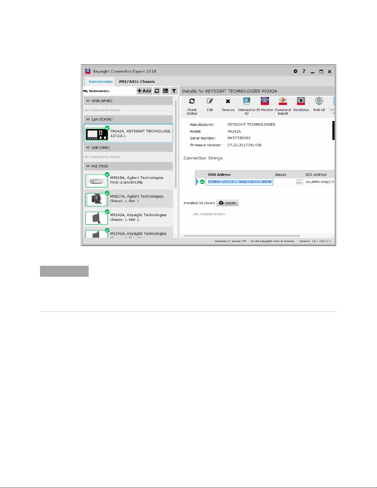
2 In the Connection Expert window's Instruments tab, select the connected
oscilloscope under the LAN (TCPIP0) interface.
Keysight P9241/42/43A Oscilloscopes Startup Guide 43
Page 44
8 Applications Programming Interface (API) Overview
NOTE
The oscilloscope appears under the LAN (TCPIP0) interface when the P9241/42/43A
oscilloscope's driver is connected (see "Open the P924xA Oscilloscope Soft Front
Panel (SFP)" on page 26).
The oscilloscope also appears under the PXI (PXI0) interface, but trying to send SCPI
commands through that interface gives an "Operation not supported" error.
3 In the Details for the selected oscilloscope, click Interactive IO.
4 To test SCPI commands In the Keysight Interactive IO window, enter commands
in the Command field and click Send Command, Read Response, or Send & Read.
44 Keysight P9241/42/43A Oscilloscopes Startup Guide
Page 45

Applications Programming Interface (API) Overview 8
5 To exit the Keysight Interactive IO application, choose Connect > Exit from the
menu.
Using the SFP and the Remote API at the Same Time
In general, you can use the Soft Front Panel (SFP) and the remote applications
programming interface (API) together, at the same time. This can be useful, for
example, because it lets you change oscilloscope settings while debugging remote
programs.
However, the SFP can become "locked out" while the oscilloscope waits for a
waveform to become fully acquired. This can happen, for example, after these
SCPI commands/queries: :WAVeform:DATA?, :WAVeform:PREamble?,
:LISTer:DATA?, :SEARch:COUNt?, :DIGitize, or :SINGle. In these situations, you can
clear the remote operation in progress by sending a Device Clear to the remote
user interface.
Keysight P9241/42/43A Oscilloscopes Startup Guide 45
Page 46

8 Applications Programming Interface (API) Overview
Sending a Device Clear to the Remote Interface
Every remote programming library gives you a way to send an IEEE 488.1-style
Device Clear. For example, the IVI-COM library provides the System2.ClearIO
method. Another easy way to send a Device Clear is through the IO Libraries
Suite's Interactive IO application.
1 On a networked PC that has the IO Libraries Suite installed, click the Keysight
IO Control icon in the taskbar and choose Utilities > Interactive IO from the popup
menu.
2 In the Keysight Interactive IO application, choose Connect > Connect....
3 In the Connect dialog box, enter the oscilloscope's HiSLIP address into the
Resource Name field and click OK.
The oscilloscope's HiSLIP address can be cut-and-pasted from your remote
program or you can piece it together from the controller PC's IP address (or
hostname) and the oscilloscope's PXI address. For example if the controller
PC's IP address is "127.0.0.1" (or hostame is "lab-pxi-3.cos.is.keysight.com")
46 Keysight P9241/42/43A Oscilloscopes Startup Guide
Page 47

Applications Programming Interface (API) Overview 8
and the oscilloscope's PXI address is "PXI37::0::0::INSTR", the oscilloscope's
HiSLIP address is "TCPIP0::10.112.93.141::hislip37-0.0::INSTR" (or
"TCPIP0::lab-pxi-3.cos.is.keysight.com::hislip37-0.0::INSTR").
If you are running the Interactive IO application on the controller PC, you can
use the "127.0.0.1" localhost IP address, for example,
"TCPIP0::127.0.0.1::hislip37-0.0::INSTR".
4 When connected, click Device Clear.
5 To exit the Keysight Interactive IO application, choose Connect > Exit from the
menu.
Keysight P9241/42/43A Oscilloscopes Startup Guide 47
Page 48

8 Applications Programming Interface (API) Overview
48 Keysight P9241/42/43A Oscilloscopes Startup Guide
Page 49

Keysight P9241/42/43A Oscilloscopes
Startup Guide
9 Reference
Environmental Conditions / 49
Probes and Accessories / 50
Specifications and Characteristics / 50
Measurement Category / 50
Product Markings / 51
Environmental Conditions
Environment Indoor use only.
Weight 2.50 kg
Dimensions
(W x H x D)
Ambient
temperature
Humidity 95% rH, non-condensing to temperatures up to 40 °C decreasing linearly to
Altitude Operating: 3,000 m (9,842 ft)
Pollution Degree The P9241/42/43A oscilloscopes may be operated in environments of Pollution
Pollution Degree
Definitions
177 mm x 50 mm x 335 mm
Operating: 0 °C to +55 °C
Non-operating: –40 °C to +70 °C
50% rH at 55 °C
Non-operating: 4,500 m (14,764 ft)
Degree 2 (or Pollution Degree 1).
Pollution Degree 1: No pollution or only dry, non-conductive pollution occurs.
The pollution has no influence. Example: A clean room or climate controlled
office environment.
Pollution Degree 2. Normally only dry non-conductive pollution occurs.
Occasionally a temporary conductivity caused by condensation may occur.
Example: General indoor environment.
Pollution Degree 3: Conductive pollution occurs, or dry, non-conductive
pollution occurs which becomes conductive due to condensation which is
expected. Example: Sheltered outdoor environment.
49
Page 50

9 Reference
WARNING
Probes and Accessories
For a list of the probes and accessories that are compatible with the
P9241/42/43A oscilloscopes, see the data sheet at:
www.keysight.com/products/P9241A
See Also For more information on probes and accessories, see www.keysight.com for:
• Probes and Accessories Selection Guide (5989-6162EN)
• InfiniiVision Oscilloscope Probes and Accessories Selection Guide Data Sheet
(5968-8153EN)
• For compatibility information, manuals, application notes, data sheets,
selection guides, SPICE models, and more for oscilloscope probes, see the
Probe Resource Center at: www.keysight.com/find/PRC
Specifications and Characteristics
Please see the oscilloscope data sheet for complete, up-to-date specifications and
characteristics. To download the data sheet for the P9241/42/43A oscilloscopes,
please visit: www.keysight.com/products/P9241A
Measurement Category
• "Oscilloscope Measurement Category" on page 50
• "Measurement Category Definitions" on page 50
Oscilloscope Measurement Category
The Keysight P9241/42/43A oscilloscopes are not intended to be used for
measurements in Measurement Category II, III, or IV.
Use this instrument only for measurements within its specified measurement
category (not rated for CAT II, III, IV). No transient overvoltages allowed.
Measurement Category Definitions
The "Not rated for CAT II, III, IV" measurement category is for measurements
performed on circuits not directly connected to MAINS. Examples are
measurements on circuits not derived from MAINS, and specially protected
(internal) MAINS derived circuits. In the latter case, transient stresses are variable;
for that reason, the transient withstand capability of the equipment is made known
to the user.
50 Keysight P9241/42/43A Oscilloscopes Startup Guide
Page 51

Measurement category II is for measurements performed on circuits directly
MSIP-REMKst-1A16182
connected to the low voltage installation. Examples are measurements on
household appliances, portable tools and similar equipment.
Measurement category III is for measurements performed in the building
installation. Examples are measurements on distribution boards, circuit-breakers,
wiring, including cables, bus-bars, junction boxes, switches, socket-outlets in the
fixed installation, and equipment for industrial use and some other equipment, for
example, stationary motors with permanent connection to the fixed installation.
Measurement category IV is for measurements performed at the source of the
low-voltage installation. Examples are electricity meters and measurements on
primary overcurrent protection devices and ripple control units.
Product Markings
These symbols are used on the P9241/42/43A oscilloscopes.
Reference 9
Symbol Description
Caution, refer to accompanying documentation
This symbol indicates separate collection for electrical and electronic
equipment mandated under EU law as of August 13, 2005. All electric
and electronic equipment are required to be separated from normal waste
for disposal (Reference WEEE Directive 2002/96/EC).
South Korean Certification (KC) mark; includes the marking's identifier
code which follows this format:
MSIP-REM-YYY-ZZZZZZZZZZZZZZ.
The RCM mark is a registered trademark of the Australian
Communications and Media Authority.
Indicates the time period during which no hazardous or toxic substance
elements are expected to leak or deteriorate during normal use. Forty
years is the expected useful life of the product.
The CE mark is a registered trademark of the European Community.
ICES / NMB-001 Cet appareil ISM est conforme a la norme NMB du
Canada. This is a marking to indicate product compliance with the
Industry Canadian Interference-Causing Equipment Standard
(ICES-001).
This is also a symbol of an Industrial Scientific and Medical Group 1 Class
A product (CISPR 11, Clause 4).
The CSA mark is a registered trademark of the CSA International.
Keysight P9241/42/43A Oscilloscopes Startup Guide 51
Page 52

9 Reference
52 Keysight P9241/42/43A Oscilloscopes Startup Guide
Page 53

Index
Numerics
10 MHz Ref I/O, 19
A
accessories, 50
airflow requirements, 25
altitude, 49
API overview, 41
ARINC 429 serial triggering and
analysis, 14
Autoscale, undo, 35
Aux Out, 19
Aux Out output, 21
B
built-in help, 32
C
CAN serial triggering and analysis, 14
Channel 1 input, 20
Channel 2 input, 20
channel input BNC connectors, 19
characteristics, 50
chassis firmware, updating, 17
chassis ground terminal, 19, 21, 22
cleaning, 23
communications problems, 29
compensate passive probes, 35
copyright, 2
CXPI trigger and decode, 14
Czech user interface, 33
D
damage, inspect for, 12
data sheet, 50
default configuration, 33
default setup, 33
Demo 1 terminal, 36
Device Clear to remote interface, 46
dimensions, 49
display, area, 38
display, interpreting, 37
display, softkey labels, 39
display, status line, 38
driver not connected, LED off, 20
E
English user interface and Quick Help, 33
environmental characteristics, 49
Ext Trig input, 19, 21
F
firmware update, 17
firmware, chassis, updating, 17
French user interface and Quick Help, 33
frequency requirements, power source, 25
frequency response analyzer, 14
front panel features, 19
G
Gen Out, 19
Gen Out output, 21
German user interface and Quick Help, 33
graphical user interface language, 33
H
hardware self test, 28
help, built-in, 32
humidity, 49
I
I2C serial triggering and analysis, 13
Identify LED, 20
Identify Oscilloscope blinking blue LED, 20
indoor use only, 49
information area, 38
inputs, 20
Interactive IO, 43, 46
Interactive IO, launching from Connection
Expert on the Host PC, 43
introduction, 7
Italian user interface and Quick Help, 33
IVI drivers, 41
J
Japanese user interface and Quick Help, 33
K
Keysight InfiniiVision Launcher, oscilloscope
not listed in, 27
Keysight Interactive IO application, 46
Keysight IO Control icon, 43, 46
Korean user interface and Quick Help, 33
L
LabVIEW driver, 42
language, user interface, 33
LED operation, 20
LEDs, oscilloscope, 19
LIN serial triggering and analysis, 14
line voltage, 25
lock cable hole, 22
M
markings, product, 51
mask limit testing, 13
measurement category, definitions, 50
measurement, making a, 31
menu line, 39
MIL-STD 1553 serial triggering and
analysis, 14
model options, 13
N
NFC automated test, 14
notices, 2
O
Operation not supported error in Interactive
IO, 44
oscilloscope FPGA update, 17
oscilloscope not listed in Keysight
InfiniiVision Launcher, 27
oscilloscope, connecting, 19
outputs, 20
Keysight P9241/42/43A Oscilloscopes Startup Guide 53
Page 54

Index
P
passive probes, 13
passive probes, compensating, 35
Polish user interface and Quick Help, 33
pollution degree, 49
pollution degree, definitions, 49
Portuguese user interface and Quick
Help, 33
power consumption, 25
power requirements, 25
power supply connection, 22
power switch, 26
power-on, 25
Probe Comp terminal, 19, 21
probes, 50
probes, connecting to oscilloscope, 31
probes, passive, compensating, 35
Q
Quick Help, 32
R
rear panel connectors, 22
Ref I/O, 19
Ref I/O input/output, 21
related documentation, 8
requirements, airflow, 25
requirements, PC, 15
return for service, 12
RS232/UART serial triggering and
analysis, 14
Run state LED, 20
running acquisitions, LED green color, 20
Russian user interface and Quick Help, 33
T
temperature, ambient, 49
Thai user interface and Quick Help, 33
Traditional Chinese user interface and Quick
Help, 33
training signals, 36
Turkish user interface, 33
U
unpack and inspect, 11
USB 3.0 port required, 23
USB 3.0 To Host PC port, 22
user interface language, 33
V
ventilation requirements, 25
verify operation, 25
W
waiting for single acquisition, LED amber
color, 20
warranted specifications, 50
warranty, 2
waveform generator, 14
WaveGen output LED, 20
WaveGen/Identify LED, 20
weight, 49
S
SCPI interface, 42
SENT triggering and analysis, 14
setup, default, 33
SFP and remote API, concurrent, 45
shipment contents, 13
shipment contents, P9241/42/43A, 13
Simplified Chinese user interface and Quick
Help, 33
soft front panel, opening, 26
softkey labels, 39
software installation, overview, 15
software, installing, 15
Spanish user interface and Quick Help, 33
specifications, 50
startup sequence, 7
status line, 38
stopped acquisitions, LED red color, 20
54 Keysight P9241/42/43A Oscilloscopes Startup Guide
 Loading...