

Page 1

Keysight USB Type-C
Connectivity Solution
(Describes Keysight N7015A / 6A / 7A / 8A
Type-C Test Fixtures)
Distributed by:
User Guide
dataTec ▪ Ferdinand-Lassalle-Str. 52 ▪ 72770 Reutlingen ▪ Tel. 07121 / 51 50 50 ▪ Fax 07121 / 51 50 10 ▪ info@datatec.de ▪ www.datatec.de
Page 2

Notices
CAUTION
WARNING
© Keysight Technologies 2015-2017
No part of this manual may be reproduced in
any form or by any means (including electronic storage and retrieval or translation
into a foreign language) without prior agreement and written consent from Keysight
Technologies as governed by United States
and international copyright laws.
Manual Part Number
N7015-97005
Edition
Fifth Edition, October 30, 2017
Available in electronic format only
Warranty
THE MATERIAL CONTAINED IN THIS
DOCUMENT IS PROVIDED "AS IS," AND IS
SUBJECT TO BEING CHANGED, WITHOUT
NOTICE, IN FUTURE EDITIONS. FURTHER,
TO THE MAXIMUM EXTENT PERMITTED BY
APPLICABLE LAW, KEYSIGHT DISCLAIMS
ALL WARRANTIES, EITHER EXPRESS OR
IMPLIED WITH REGARD TO THIS MANUAL
AND ANY INFORMATION CONTAINED
HEREIN, INCLUDING BUT NOT LIMITED TO
THE IMPLIED WARRANTIES OF
MERCHANTABILITY AND FITNESS FOR A
PARTICULAR PURPOSE. KEYSIGHT SHALL
NOT BE LIABLE FOR ERRORS OR FOR
INCIDENTAL OR CONSEQUENTIAL
DAMAGES IN CONNECTION WITH THE
FURNISHING, USE, OR PERFORMANCE OF
THIS DOCUMENT OR ANY INFORMATION
CONTAINED HEREIN. SHOULD KEYSIGHT
AND THE USER HAVE A SEPARATE WRITTEN
AGREEMENT WITH WARRANTY TERMS
COVERING THE MATERIAL IN THIS
DOCUMENT THAT CONFLICT WITH THESE
TERMS, THE WARRANTY TERMS IN THE
SEPARATE AGREEMENT WILL CONTROL.
Technology Licenses
The hardware and/or software described in
this document are furnished under a license
and may be used or copied only in accordance with the terms of such license.
U.S. Government Rights
The Software is "commercial computer software," as defined by Federal Acquisition
Regulation ("FAR") 2.101. Pursuant to FAR
12.212 and 27.405-3 and Department of
Defense FAR Supplement ("DFARS")
227.7202, the U.S. government acquires
commercial computer software under the
same terms by which the software is customarily provided to the public. Accordingly,
Keysight provides the Software to U.S. government customers under its standard commercial license, which is embodied in its
End User License Agreement (EULA), a copy
of which can be found at http://www.key-
sight.com/find/sweula. The license set
forth in the EULA represents the exclusive
authority by which the U.S. government may
use, modify, distribute, or disclose the Software. The EULA and the license set forth
therein, does not require or permit, among
other things, that Keysight: (1) Furnish technical information related to commercial
computer software or commercial computer
software documentation that is not customarily provided to the public; or (2) Relinquish
to, or otherwise provide, the government
rights in excess of these rights customarily
provided to the public to use, modify, reproduce, release, perform, display, or disclose
commercial computer software or commercial computer software documentation. No
additional government requirements beyond
those set forth in the EULA shall apply,
except to the extent that those terms, rights,
or licenses are explicitly required from all
providers of commercial computer software
pursuant to the FAR and the DFARS and are
set forth specifically in writing elsewhere in
the EULA. Keysight shall be under no obligation to update, revise or otherwise modify
the Software. With respect to any technical
data as defined by FAR 2.101, pursuant to
FAR 12.211 and 27.404.2 and DFARS
227.7102, the U.S. government acquires no
greater than Limited Rights as defined in
FAR 27.401 or DFAR 227.7103-5 (c), as
applicable in any technical data. 52.227-14
(June 1987) or DFAR 252.227-7015 (b)(2)
(November 1995), as applicable in any technical data.
Safety Notices
A CAUTION notice denotes a hazard. It
calls attention to an operating procedure, practice, or the like that, if not
correctly performed or adhered to,
could result in damage to the product
or loss of important data. Do not proceed beyond a CAUTION notice until
the indicated conditions are fully
understood and met.
A WARNING notice denotes a hazard.
It calls attention to an operating procedure, practice, or the like that, if not
correctly performed or adhered to,
could result in personal injury or
death. Do not proceed beyond a
WARNING notice until the indicated
conditions are fully understood and
met.
2 Keysight USB Type-C Connectivity Solution User Guide
Page 3

Contents
1 Type-C Connectivity Solution Overview
2 N7015A Type-C High Speed Test Fixture
Introduction to the Type-C Test Fixtures 8
Usage Scenarios for the Type-C Test Fixtures 9
How the Type-C Test Fixtures Work Together 10
Type-C Connectivity Test Kits 11
N7015A Type-C High Speed Test Fixture Kit 11
N7018A Type-C Test Controller Kit 12
ZA0200 Type-C Core Connectivity Kit 12
Compatibility with Oscilloscopes 14
For More Information... 15
Components 18
N7015A Channels Identification Rings 19
N7015A Insertion Loss Plot 20
Cleaning the N7015A Test Fixture 21
3 N7018A Type-C Test Controller
Components 24
Supported ALT Modes 27
Features 28
Powering the N7018A and DUT 30
Powering the N7018A 30
Powering the DUT as a Provider or a Consumer 30
Setting up the Wire Harness for the External Power Supply 31
Pre-use Warnings and Connectivity Precautions 33
Cleaning the N7018A Test Controller 34
4 N7016A Type-C Low Speed Test Fixture
Introduction 36
Features 37
Keysight USB Type-C Connectivity Solution User Guide 3
Page 4

Contents
N7016A Block Diagrams 38
Connection Block Diagram 38
VBUS Control Block Diagram 39
SBU Switch Block Diagram 39
CC Control Block Diagram 40
Significance and Values of Rp, Rd, and Ra Termination Resistors in the USB Type-C Connector: 41
Control Setup Block Diagram 42
Powering the N7016A 43
Replacing the N7016A Fuse 45
5 N7017A Type-C Receptacle Adapter
Insertion Loss Plot for N7015A with N7017A 49
6 Recommended Accessories
N2787A 3D Probe Positioner 51
N2823A or N5448B Coaxial Phase Matched Cable Pair 51
InfiniiMax 1130B Series Probe Amplifier 54
E2678B Socketed Head for InfiniiMax Probe 54
Passive Probe 54
7 Sample Setups for Type-C Testing
Testing a USB 3.1 Host (Tx) 56
Testing a DisplayPort (2+2) Source (Tx and AUX Channel Testing) 57
Testing a DisplayPort (4 lanes) Source (Tx and AUX Channel Testing) 58
Testing a Thunderbolt 3 Host (Tx) 59
Testing a USB Power Delivery Consumer over Type-C Interface 60
Testing a USB Power Delivery Provider with N7018A set to Sink Current 61
Testing a USB Power Delivery Provider over Type-C Interface 62
8 Accessing Type-C Signals
Overview 64
Probing the CC1, CC2, and VBUS Signals 65
Probing the SBU1 and SBU2 (Secondary Bus) Signals 67
Probing the SBU1 and SBU2 Signals at the N7015A Test Fixture 67
Probing the SBU1 and SBU2 Signals at the N7016A or N7018A 67
Probing the D+ and D- Signals 70
4 Keysight USB Type-C Connectivity Solution User Guide
Page 5

9 Installing and Configuring Software Components for Type-C Testing
If you are Using N7018A 72
Installing the N7018A Type-C Test Controller Software 72
Launching the N7018A Software GUI 72
Establishing Connectivity between the N7018A Hardware and Software GUI 74
Setting up the N7018A Emulation Role and ALT Mode and Establishing Connection with DUT 75
Setting up and Establishing a Power Delivery Contract with DUT 78
Configuring LFPS Settings (applicable to USB 3.1 testing only) 82
Viewing the Status of the N7018A Connection with the DUT 85
If you are Using N7016A 87
Installing the N7016A Type-C Low Speed Signal Access and Control Fixture Software 87
Installing the Appropriate Keysight Compliance Application Software 92
10 Schematic Diagrams and Pinouts
N7015A Dimensions 94
N7015A Pinout 95
N7018A Dimensions 98
N7016A Dimensions 99
N7017A Receptacle Adapter Dimensions 100
N7017A Receptacle Adapter Pinout 101
Signal Routing when using the N7017A Receptacle Adapter 102
11 Downloading the S-parameter File
12 Characteristics and Specifications
Environmental Characteristics 105
Specifications 105
13 Safety and Regulatory Information
Instrument Markings 108
Index
Keysight USB Type-C Connectivity Solution User Guide 5
Page 6

Contents
6 Keysight USB Type-C Connectivity Solution User Guide
Page 7

Keysight Type-C Connectivity Solution
User Guide
1 Type-C Connectivity Solution
Overview
Introduction to the Type-C Test Fixtures / 8
Usage Scenarios for the Type-C Test Fixtures / 9
How the Type-C Test Fixtures Work Together / 10
Type-C Connectivity Test Kits / 11
Compatibility with Oscilloscopes / 14
For More Information... / 15
This chapter introduces the Keysight Type-C connectivity test fixtures and describes how these function
together to allow you to perform integrated testing for various interfaces supported over Type-C.
The details of each of these test fixtures and the hardware and software setup information are included in
the subsequent chapters.
Page 8

1 Type-C Connectivity Solution - Overview
NOTE
Introduction to the Type-C Test Fixtures
The N7015A, N7016A, N7017A, and N7018A Type-C test fixtures provide a comprehensive and
complete testing solution for automated compliance testing, characterization, validation, and
debugging of your Type-C host/device including various Type-C interfaces such as USB, DisplayPort,
and Thunderbolt
fixtures play in the Type-C testing scenario.
TM
. The following picture highlights the broad role that each of these Type-C test
The N7018A is a superset of most of the features of the N7016A and additionally provides
power delivery controller capabilities and integrated testing over Type-C interfaces
through a single connection. This makes the N7018A a full replacement of the N7016A.
8 Keysight Type-C Connectivity Solution User Guide
Page 9

Usage Scenarios for the Type-C Test Fixtures
You can use the Type-C test fixtures described in this guide in the following scenarios.
• USB 2.0 Tx and Rx testing
• USB 3.1 Gen 1 (5Gbs) and Gen 2 (10Gbs) Tx and Rx testing
• Thunderbolt 3 over Type-C Tx and Rx testing
• DisplayPort 1.3 over Type-C testing including:
• 2+2 mode: Two DisplayPort differential lanes + two simultaneous USB 3.1 differential
lanes
• Four DisplayPort differential lanes
• DisplayPort AUX Channel testing
• USB-Power Delivery over Type-C (Provider and Consumer and ALT Modes Control testing)
Sample setups and specific notes for these scenarios are included in the chapter “Sample Setups for
Type - C Testing" on page 55.
Type-C Connectivity Solution - Overview 1
Keysight Type-C Connectivity Solution User Guide 9
Page 10

1 Type-C Connectivity Solution - Overview
How the Type-C Test Fixtures Work Together
A high level overview of how these Type-C test fixtures work together is provided below. For details,
refer to the individual chapters in this guide dedicated to these fixtures.
The N7015A test fixture connects to a DUT and a compatible oscilloscope to break out four
differential lanes of Type-C high-speed signals from the DUT to the oscilloscope. These high-speed
signals can be monitored and analyzed using the Keysight Infiniium software installed on the
oscilloscope.
For low-speed power and control signals access, the N7015A test fixture connects to the N7018A
test controller or the N7016A test fixture and passes the Vbus, SBU, and CC lines to the N7018A /
N7016A via a USB Type-C (plug style) cable. There are probe points for Vbus, SBU, and CC lines on
the N7018A or N7016A to allow you to probe these low-speed signals at these fixtures.
The USB Type-C cable that connects the N7015A to the N7018A also serves as the connection
mechanism between the N7018A and DUT with the N7015A test fixture in between. Using this cable,
the N7018A establishes a Type-C connection and a standard 5V PD contract with DUT and
advertises the user-selected mode of operation (ALT Mode) and power delivery role to the DUT.
Once the connection is established, the N7018A can negotiate a new PD contract with the DUT on
the selected CC line using the USB PD protocol. This PD contract is as per the settings that you
configured for the N7018A.
When USB PD negotiations are complete, the N7018A enables the appropriate power path and
negotiates and enters the user-selected ALT Mode. It enables, discovers, configures, and
enters/exits the selected Alt Mode with the DUT via a USB PD protocol handshake.
All these configurations and control of the N7018A test controller including connection, power role,
ALT modes, and power delivery contract settings are done using the N7018A software (see page 72).
To provide power to the N7016A / N7018A test fixtures and control and configure these fixtures
using their software, you connect these to an oscilloscope or a host computer via the supplied USB
cable. An external power supply is needed if the N7018A / N7016A is acting as a power delivery
provider to DUT.
If you are using the N7016A, a power delivery controller is also needed. If you are using the N7018A,
then you do not need a power delivery controller as the N7018A acts as a power delivery controller
as well.
Besides signals monitoring and analysis, characterization, and debugging, these test fixtures also
allow you to run various compliance tests. The N7018A / N7016A test fixtures are integrated with a
number of Keysight compliance applications software to allow you to do automated compliance
testing when using these test fixtures.
10 Keysight Type-C Connectivity Solution User Guide
Page 11

Type-C Connectivity Test Kits
The Type-C test fixtures documented in this guide are available as Keysight Type-C connectivity test
kits. These kits include the test fixture(s) as well as other components needed for operating these
test fixtures. These kits contain standard components as well as optional components that you can
choose to buy when ordering the kit.
The following Type-C test kits are available.
N7015A Type-C High Speed Test Fixture Kit
Type-C Connectivity Solution - Overview 1
Figure 1 N7015A Type-C Test Kit with N7015A-016 Product Option
You can order this test kit with the following product options:
Item Part Number Quantity
N7015A Type-C High Speed Test Fixture
(standard component of the test kit)
Type-C High Speed Test Fixture N7015A 1
Wrench 8710-2803 1
N7016A Type-C Low Speed Signal Access and Control Fixture
(optional component of the test kit. Can be ordered with the test kit as the N7015A-016 option or separately as a standalone
product (model number N7016A)
Low Speed Fixture N7016A 1
Power Supply Connector Plug 0360-2693 1
USB Cable 8121-1242 1
Keysight Type-C Connectivity Solution User Guide 11
Page 12

1 Type-C Connectivity Solution - Overview
USB 2.0 Cable
Power Supply
Connector Plug
Type-C Test
Controller
Item Part Number Quantity
Replacement Fuses 2110-0623 4
N7017A Type-C Receptacle Adapter
(optional component of the test kit. Can be ordered with the test kit as the N7015A-017 option or separately as a standalone
product (model number N7017A)
Receptacle Adapter N7017A 1
N7018A Type-C Test Controller Kit
Item Part Number Quantity
Standard component of the test kit
Type-C Test Controller N7018A 1
Power Supply Connector Plug 0360-2693 1
USB Cable 8121-1242 1
ZA0200 Type-C Core Connectivity Kit
This kit includes Type-C test fixtures as well as the equipment and accessories that are
recommended for use with these test fixtures.
The following table lists the kit contents.
Item Part Number Quantity
Type-C High-speed Test Fixture N7015A 1
Type-C Test Controller N7018A 1
Type-C Receptacle Adapter N7017A 1
1m Phase Matched Cables N2823A 2
12 Keysight Type-C Connectivity Solution User Guide
Page 13

Type-C Connectivity Solution - Overview 1
Item Part Number Quantity
Connector Savers 5061-5311 10
Blocking Capacitors N9398C 4
4-slots Low-Profile Modular Power System
Mainframe
Source/Measure Unit (power supply/load module) N6786A 1
N6701C 1
Keysight Type-C Connectivity Solution User Guide 13
Page 14

1 Type-C Connectivity Solution - Overview
Compatibility with Oscilloscopes
The Type-C test fixtures included in this guide are compatible with the following Keysight oscilloscopes:
Compatible Oscilloscopes
• Infiniium 90000A Series Oscilloscopes
• Infiniium Z-Series Oscilloscopes
• Infiniium V-Series Oscilloscopes
Compatible Oscilloscope Software
Infiniium baseline software version 6.10 or higher
Is Your Oscilloscope Software Up-to-Date?
Keysight periodically releases software updates to support your probe, fix known defects,
and incorporate product enhancements. To download the latest firmware, go to
www.keysight.com and search for your oscilloscope’s series. Then click on the “Drivers,
Firmware & Software” tab.
14 Keysight Type-C Connectivity Solution User Guide
Page 15

For More Information...
You can find application notes, videos, data sheets, guides, methods of Implementation documents
as well as general information about various products that Keysight offers for USB Type-C Interface
testing at:
http://www.keysight.com/find/type-c
Type-C Connectivity Solution - Overview 1
Keysight Type-C Connectivity Solution User Guide 15
Page 16

1 Type-C Connectivity Solution - Overview
16 Keysight Type-C Connectivity Solution User Guide
Page 17

Keysight Type-C Connectivity Solution
User Guide
2 N7015A Type-C High Speed
Test Fixture
Components / 18
N7015A Insertion Loss Plot / 20
Cleaning the N7015A Test Fixture / 21
The N7015A Type-C high speed test fixture comes with a plug style Type-C connector mated to the
receptacle on the USB host/device to enable you to verify and debug USB 3.1 Gen 2 designs, and
designs using other high-speed signal standards that support the Type-C connector. It can also
connect to a USB device with a plug connector using the N7017A Type-C receptacle adapter.
It breaks the signals into four differential lanes of high speed Tx and Rx signals and USB 2.0 D+/Dsignals to an oscilloscope input. It can also work with either N7018A or N7016A test fixtures to pass
low-speed power and control signals to either of these for probing and analysis.
Using the N7015A, you can obtain the most accurate measurements with the best signal integrity by
supporting bandwidth up to 30 GHz with low noise levels.
By providing a Type-C connection with the DUT, it allows the N7018A test controller to establish
Power Delivery (PD) contracts and enter/exit various ALT modes with the DUT.
Page 18

2 N7015A Type-C Hight Speed Test Fixture
Components
Figure 2 N7015A Type-C High Speed Test Fixture
Component Description
Type-C Connection The Type-C connector that connects the N7015A:
Matched Cable Pairs for
High-speed data lanes
D± Cables D± lanes are used for USB 2.0 data transmissions.
SBU1 / SBU2 Differential Test
Point
Interface to N7016A or N7018A
test fixtures
• either to a receptacle connector on the DUT
• or to a receptacle adapter (such as the N7017A) during a Type-C port extension or a
receiver test calibration
The Type-C connection of N7015A breaks out the following high-speed data differential data
lanes:
• four data lanes across eight pins, (TX1±, RX1±, TX2±, RX2±). These lanes are capable
of carrying USB 3.1, DisplayPort, or Thunderbolt signals available for use during Alt
mode transmissions.
The test point to differentially probe the SBU1/SBU2 signals directly at the N7015A.
This is particularly useful for DisplayPort AUX channel signal evaluation.
For details, see page 67.
The USB Type-C (plug style) cable that connects the N7015A to the N7018A or N7016A test
fixture. Through this cable connection, the N7015A passes low-speed power and control
signals to these test fixtures.
This cable connection also serves as the connection mechanism between the N7018A and
DUT with the N7015A test fixture in between.
18 Keysight Type-C Connectivity Solution User Guide
Page 19

N7015A Channels Identification Rings
Channel Identification
Rings
The high-speed Tx and Rx cables and the USB 2.0 cables of the N7015A test fixture have channel
identification rings. These rings allow you to color-code each differential lane of Type-C high-speed
signals and USB 2.0 signals and thereby easily identify these signals ensuring an error-free
connection of the cables to the oscilloscope.
You can either use the default assignment in which these rings are assigned to cables or you can
change this default assignment to define your own color coding.
N7015A Type-C Hight Speed Test Fixture 2
In the default assignment:
• The cable with a single ring represents a minus (-) high-speed signal and the cable with a set of
two rings represents a plus (+) high-speed signal.
• For USB 2.0 signals, the cable with a single ring represents a plus (+) signal and the cable with no
rings indicates a minus (-) signal.
Keysight Type-C Connectivity Solution User Guide 19
Page 20

2 N7015A Type-C Hight Speed Test Fixture
N7015A Insertion Loss Plot
Figure 3 N7015A Fixture Insertion Loss Plot
For the insertion loss plot of the N7015A test fixture when used with the N7017A receptacle adapter,
refer to the topic “Insertion Loss Plot for N7015A with N7017A" on page 49.
20 Keysight Type-C Connectivity Solution User Guide
Page 21

Cleaning the N7015A Test Fixture
CAUTION
The presence of foreign particles on the contacts can degrade the N7015A Type-C connector
performance. Therefore, it is recommended that you clean the N7015A Type-C Connector in case
there is a suspicion of contamination.
To clean the Type-C connector:
1 Disconnect the N7015A from the oscilloscope, any test fixtures, and DUT.
2 Gently clean the Type-C connector by applying an electrical contact cleaner.
3 Connect and disconnect the Type-C connector a few times to dislodge any contaminates stuck
on the connector.
4 Apply additional contact cleaner to remove any remaining contaminates.
5 Make sure the connector is completely dry before reconnecting it for use by:
• either using forced air to remove excess contact cleaner.
• or allowing the connector to dry.
N7015A Type-C Hight Speed Test Fixture 2
Do not try to clean the probe using Isopropyl alcohol as it may leave a
residue.
Keysight Type-C Connectivity Solution User Guide 21
Page 22

2 N7015A Type-C Hight Speed Test Fixture
22 Keysight Type-C Connectivity Solution User Guide
Page 23

Keysight Type-C Connectivity Solution
NOTE
User Guide
3 N7018A Type-C Test
Controller
Components / 24
Supported ALT Modes / 27
Features / 28
Powering the N7018A and DUT / 30
Pre-use Warnings and Connectivity Precautions / 33
Cleaning the N7018A Test Controller / 34
The N7018A Type-C Test Controller emulates a power delivery link partner to help you validate,
characterize, or debug various Type-C host and devices. As a power delivery link partner, it allows you to
control the interface and validate ALT modes entry/exits over Type-C.
By supporting various operating modes as a link partner to the DUT through a single connection, it allows
you to perform an integrated, unattended testing of various Type-C interfaces.
Besides emulating a link partner and supporting various ALT modes, the N7018A also provides access to
various low-speed Type-C signals for observation and measurement.
For automated testing of interfaces such as DisplayPort and Thunderbolt, it supports connectivity to
appropriate industry standard controllers for alt mode operation so that you can not only monitor but also
control the applicable Type-C interface.
The N7018A is a superset of most of the features of the N7016A and additionally provides
power delivery controller capabilities and integrated testing over Type-C interfaces
through a single connection. This makes the N7018A a full replacement of the N7016A.
Page 24

3 N7018A Type-C Test Controller
External Power
Supply Connector
USB 2.0 Cable
Connector
Thunderbolt Controller
Interface
VBUS Status
Lights
CC Connection
Lights
DisplayPort
Controller Interface
Interconnect to N7015A Rx Lines
(for LFPS Ping Control )
Interconnect for USB 2.0
signals from N7015A
SBU1 / SBU2
Probe Points
CC1 / CC2
Probe Points
GND Points
USB Type-C
Connector
VBUS Probe
Point
Back View
Front View
GND Point
Side View
Components
24 Keysight Type-C Connectivity Solution User Guide
The following table describes these N7018A components.
Page 25

Component Description
WARNING
N7018A Type-C Test Controller 3
SBU1/SBU2 Probe Points The points to probe the DUT’s SBU1/SBU2 signals that the N7015A passes to the N7018A through the
Interconnect to N7015A Rx
Lines
(for LFPS Ping Control)
Interconnect for USB 2.0
signals from N7015A
VBUS Status Lights The N7018A passively detects the VBUS level. If VBUS is present, the appropriate LED glows.
CC Connection Lights Based on whether you select the Normal (CC1) or Flipped (CC2) option as the N7018A Type-C connector
USB Type-C cable connection.
Using these points, you can probe SBU signals single-ended or differentially.
See page 67 to know more.
SBU1 and SBU2 probe points may have sharp edges. Exercise caution when using
these probe points to avoid personal injury.
The four (Tx1+, Tx1-, Tx2+, and Tx2-) SMA ports on the N7018A can be used when testing USB 3.1 to
provide LFPS signals to the DUT via the N7015A.
You connect the high-speed Rx cables of the N7015A to these SMA ports for LFPS signaling.
Each of these SMA connectors can accept a maximum of 5V.
These D+ / D- SMA ports on the N7018A are used to maintain an optional USB2.0 connection in ALT
modes. You connect the D+ / D- cables of the N7015A to these SMA ports.
These ports can be used for probing USB 2.0 signals only if another adapter board is used.
Each of these SMA connectors can accept a maximum of 5V.
• 5V
• 12V
• 20V
orientation in the N7018A software GUI, the applicable LED glows.
• CC1 - Indicates that the CC1 (CC line on the top of the N7018A USB Type-C connector) will be used
as the communication channel for the N7018A connection to DUT. This represents the Normal
connector orientation (right-side up) of the N7018A.
• CC2 - Indicates that the CC2 (CC line on the bottom of the N7018A USB Type-C connector) will be
used as the communication channel for the N7018A connection to DUT. This represents the Flipped
connector orientation (upside down) of the N7018A.
See page 75 for more information on connector orientation.
External Power Supply
Connector
DisplayPort Controller Interface The interface to connect the N7018A to a DisplayPort AUX controller such as the Unigraf DPR-100 AUX
Thunderbolt Controller
Interface
USB 2.0 Cable Connector The connector to establish connectivity between the N7018A and oscilloscope / host computer via the
CC1 / CC2 Probe Points The points to probe the DUT’s CC1 and CC2 signals that the N7015A passes to the N7018A through the
Keysight Type-C Connectivity Solution User Guide 25
The connector to connect the N7018A to an external power supply (Keysight N6700-series Low Profile
Modular Power System Mainframe such as N6701C or N6702C with at least one N6786A
Source/Measure Unit).
A 6-pin power supply connector plug is provided with the N7018A for this connector.
See page 30 to know more.
Controller or Unigraf DPT-200 DisplayPort AUX Controller.
Using this interface, the DUT’s SBU signals (AUX+ and AUX-) received from the N7015A can be routed to
the connected DisplayPort Controller to not only monitor but also control the DUT’s DisplayPort state.
See page 57 for a sample hardware setup for DisplayPort testing.
The interface to connect the N7018A to a Thunderbolt controller such as Wilder controller.
Using this interface, the DUT’s SBU signals (LFTX and LFRX) received from the N7015A can be routed to
the connected Thunderbolt Controller to control the Thunderbolt 3 connection.
See page 59 for a sample hardware setup for Thunderbolt 3 testing.
supplied USB 2.0 cable. This connection is needed to:
• power the N7018A hardware
• control and configure the N7018A hardware using the N7018A software GUI installed on the
oscilloscope / host computer.
USB Type-C cable connection.
See page 65 to know more.
Page 26

3 N7018A Type-C Test Controller
Component Description
GND Points GND connection points provided below the CC1. CC2, and VBUS probe points to allow you to clip the
USB Type-C Connector The USB Type-C connector to connect the N7018A to the N7015A via the USB Type-C plug style cable of
VBUS Probe Point The point to probe the DUT’s VBUS supply that the N7015A passes to the N7018A through the USB
probe grounds to these points.
the N7015A.
Using this connection, the N7015A passes the DUT’s low-speed signals ((VBUS, CC1/2, SBU1/2, GND) to
the N7018A for monitoring and full control of the Type-C interface.
This connection also serves as the connection between the N7018A and DUT with the N7015A test fixture
in between.
Type-C cable connection.
See page 65 to know more.
26 Keysight Type-C Connectivity Solution User Guide
Page 27

Supported ALT Modes
The N7018A is capable of operating at and supporting the following ALT modes of the Type-C
specifications:
• DisplayPort - The following signal configurations are supported.
• USB 3.1 Host and Device
• Thunderbolt 3
N7018A Type-C Test Controller 3
• a two-lane DisplayPort and a two-lane USB 3.1 configuration for simultaneous data and video
transfer
• a four-lane DisplayPort configuration
Keysight Type-C Connectivity Solution User Guide 27
Page 28

3 N7018A Type-C Test Controller
NOTE
Features
The table below lists some of the key features of the N7018A in the context of various emulation roles and
functions that it can perform.
As a Power Delivery Provider, the N7018A:
• advertises an initial 5V/3A PDO which is used to establish a basic 5V PD contract between the N7018A and consumer DUT. After
the initial 5V PD contract is established, the N7018A can provide for any advertised consumer PDO ranging from 5-20V and up to
5A (@ 20V) using the N6701A external power supply.
• advertises a maximum current limit that it guarantees to be able to supply to the DUT.
• displays the sink PDOs that the DUT advertised for its power operating requirements.
• allows you to select a sink PDO from the DUT’s advertised PDOs to set up a new PD contract with the DUT.
• allows you to configure its source PDO (fixed only) to advertise its power delivery capabilities to the consumer DUT.
• negotiates and sets up new PD contracts with the DUT,
For the ALT modes supported, the N7018A can support and maintain a
USB2.0 and a USB Power Delivery connection.
As a Power Delivery Consumer, the N7018A:
• advertises an initial 5V/1A PDO request which is used to establish a basic 5V PD contract between the N7018A and provider DUT.
After the initial 5V PD contract is established, the N7018A can operate at any provider PDOs advertised by the DUT ranging from
5-20V.
• advertises a maximum current limit that the provider DUT has to guarantee to be able to supply.
• displays the source PDOs that the DUT advertised for its power providing capabilities.
• allows you to select a source PDO from the DUT’s advertised PDOs to set up a new PD contract with the DUT.
• allows you to configure its sink PDO (fixed only) to advertise its power requirements to the provider DUT.
• negotiates and sets up new PD contracts with the DUT,
• can sink up to 5A in the consumer role when connected to the N6701A external power supply (set to Sink mode).
For these PD negotiations, the N7018A uses the USB Type-C CC line that you selected as the communication channel and manages
the connection to the link partner DUT via the Type-C cable connection to the N7015A test fixture.
See Also
“Power Delivery Contract Setup - Flow of Steps" on page 78
As a Power Delivery Controller, the N7018A:
• supports USB PD negotiations and ALT modes.
• control the active Type-C connection (Normal or Flipped).
• control the power role (as a provider or a consumer)
• control (swap) the data role. As a DFP, it can control the entry and exit of the modes in the sink DUT.
• control the ALT modes to be tested.
• control the power delivery (as a Power Delivery Controller)
As a UFP / DFP, the N7018A:
• can handle either of the two data roles - Upstream Facing Port (UFP) or Downstream Facing Port (DFP).
• can accept a default data role based on the power role that you configured for the N7018A.
• can accept a data role swap when initiated by the DUT.
• can initiate a data role swap itself when configured by the user to do so.
28 Keysight Type-C Connectivity Solution User Guide
Page 29

N7018A Type-C Test Controller 3
As a USB 3.1 LFPS generator, the N7018A:
• can transmit LFPS and SCD/LBPM signals (LFPS Ping, LFPS Warm Reset, or LFPS Polling patterns)
• can encode the LBPM signal as SuperSpeed (5Gbps) or SuperspeedPlus (10Gbps).
For DisplayPort DUT control, the N7018A:
• supports reconfiguration of pins on the USB Type-C connector for the selected DisplayPort mode.
• supports the following two modes of operation in DisplayPort emulation.
• Four DisplayPort lanes to transport DisplayPort streams on these four lanes.
• Two DisplayPort lanes + two simultaneous USB 3.1 lanes ( Tx and one Rx lanes) to support the simultaneous
use of USB data and DisplayPort1.3 Audio/Video streams over Type-C connector
• allows DisplayPort AUX channel testing by probing and routing the SBU1/SBU2 (reconfigured as AUX+/AUX-)
signals received from the DUT via N7015A. These signals can be routed to a DisplayPort Controller via the
DisplayPort controller interface on the N7018A.
For Thunderbolt 3 DUT control, the N7018A:
• supports probing and routing of the SBU1/SBU2 signals (LFRX and LFTX) received from the DUT via N7015A.
These signals can be routed to a Thunderbolt Controller via the Thunderbolt interface on the N7018A.
Keysight Type-C Connectivity Solution User Guide 29
Page 30

3 N7018A Type-C Test Controller
Powering the N7018A and DUT
Powering the N7018A
You can power the N7018A by connecting it to the oscilloscope or the host computer using the
supplied USB 2.0 cable.
Powering the DUT as a Provider or a Consumer
The N7018A can power the DUT when acting as a PD provider or a PD consumer.
You can connect the N7018A to an external power supply to power the DUT. Connecting to an
external power supply is mandatory when the N7018A is emulating the role of a Power Delivery
Provider. The N7018A has an external power supply port to make this connection. This is particularly
useful when testing a DUT under “No Power” or “Dead Battery” or "DUTs with no self powering"
situations.
Using an External Power Supply
When connected to an external power supply, the N7018A can accept an input voltage ranging from
0V to 20V in its PD provider role and sink up to 5A in its PD consumer role. The actual input voltage
that it uses from the external power supply as a provider depends on the PDO that you selected
when setting up the PD contract between the N7018A and DUT (see page 78).
The Keysight N6700-series Low Profile Modular Power System Mainframe such as N6701C or
N6702C with at least one Keysight N6786A Source/Measure Unit (module) can act as an external
power supply to the N7018A. One N6786A module can provide the maximum voltage at upto 20V
with the maximum current at upto 4A. If required, you can use an additional N6786A power module
in the mainframe to support the maximum voltage at upto 20V with the maximum current at upto 5A.
30 Keysight Type-C Connectivity Solution User Guide
Page 31

Setting up the Wire Harness for the External Power Supply
1 Make the wires connection between the N6786A module’s SMU connector and N7018A’s
external power supply connector as illustrated in the following picture.
N7018A Type-C Test Controller 3
Keysight Type-C Connectivity Solution User Guide 31
Page 32

3 N7018A Type-C Test Controller
NOTE
NOTE
While making these wires connection:
- ensure that the signal labels on the N7018A and N6786A are matched correctly as illustrated
While
in the picture on the previous page.
- ensure that the wires used conform to the wire gauge indicated in the picture on the previous
page.
2 Securely fasten all wires by tightening the screw terminals.
3 Use the following connector plugs to secure the wire harness.
To make these wire connections, you need a small and flat blade
screwdriver such as the Phoenix Contact SZS, 0.4 x 2.5 x 80 mm VDE
screwdriver.
8-pin output connector plug for the N6786A module’s SMU
connector. This plug is provided with the N6786A.
6-pin power supply connector plug (part number 0360-2693) for
the N7018A external power supply connector. This plug is
provided with the N7018A.
32 Keysight Type-C Connectivity Solution User Guide
Page 33

Pre-use Warnings and Connectivity Precautions
CAUTION
CAUTION
CAUTION
With USB Type-C connectors and cables involved in an N7018A and N7015A test setup, it is
essential that proper procedures are followed for connecting and disconnecting these Type-C cables
from the device/host and N7015A/N7018A test fixtures during testing. For instance, you may
experience problems when the system is disconnected with the power supply on and greater than 5V
voltage present on the VBUS.
This topic provides guidelines and precautions that you must take while connecting/disconnecting
Type-C cables. Failure to comply to these guidelines and precautions can result in damage to system
components.
The USB Type-C connector is a 24-pin fine pitch connector that can have up
to 20V on the VBUS pins, and up to 5A supplied to DUTs during testing.
Therefore, you must break the Type-C connection between the N7018A and
DUT prior to disconnecting or reconnecting any Type-C cable used in the
setup. This ensures that the VBUS is at Vsafe0V before the
disconnection/reconnection.
You use the Break Connection button in the N7018A software GUI to break
the connection. See page 74 for more details on connection.
N7018A Type-C Test Controller 3
The N7018A uses an external power supply when configured as a Power
Delivery Provider to the DUT. Therefore, in such test configurations, you
must set up all physical connections before the power supply is turned on
during testing. By doing so, you can ensure that the PD contract that allows
currents to flow between the power supply and DUT is set up only after the
physical connections have been made. This will ensure protection against
damage from disconnecting/reconnecting components with power supply
on and at high voltages.
The CC1/CC2 and SBU1/SBU2 lines are limited to 5V swings. These are
located next to the VBUS lines in the Type-C connector and the voltage on
the VBUS pins can range from 0-20V. This may cause damage to CC/SBU
lines if the Type-C cable is connected/disconnected while voltages are
present on the VBUS.
To prevent this damage, you must connect all physical connections and
cables between the N7018A/N7015A and DUT before any PD contracts are
made while running tests.
When disconnecting a Type-C cable while running tests, the PD contract
must be broken before disconnecting. This can be done by breaking the
Type-C connection using the N7018A software GUI.
Keysight Type-C Connectivity Solution User Guide 33
Page 34

3 N7018A Type-C Test Controller
CAUTION
Cleaning the N7018A Test Controller
Do not try to clean the probe using Isopropyl alcohol as it may leave a residue.
To clean the N7018A
1 Disconnect the N7018A from all external devices such as an oscilloscope, any test fixtures, or
controllers.
2 Clean the outside of the N7018A with a soft, lint free, slightly dampened cloth.
3 After cleaning, allow any residual moisture to dissipate prior to connection with any external
devices.
Do not use detergent or chemical solvents.
34 Keysight Type-C Connectivity Solution User Guide
Page 35

Keysight Type-C Connectivity Solution
User Guide
4 N7016A Type-C Low Speed
Test Fixture
Introduction / 36
Features / 37
N7016A Block Diagrams / 38
Powering the N7016A / 43
Replacing the N7016A Fuse / 45
This chapter provides details on the N7016A test fixture.
Page 36

4 N7016A Type-C Low Speed Test Fixture
NOTE
Introduction
The N7016A Type-C low-speed test fixture is used along with the N7015A High-speed test fixture to
allow monitoring and limited control of the Type-C low-speed signals that it receives from the
N7015A.
The N7016A supports termination requirements of the DUT as well as a connection to a power
delivery controller. It also provides a Type-C port to connect to a Type-C device (can be a link partner
to the DUT). Using this port, it allows you to merge and route DUT’s high-speed and low-speed
signals received via the N7015A to the Type-C device connected to this port.
Figure 4 N7016A Low Speed Test Fixture
When connecting the N7015A’s TX and RX SMA cables to the N7016A TX and RX SMA ports,
ensure that the labels on these SMA cables and SMA ports match. For instance, connect the
TX1+ cable from N7015A to TX1+ SMA port on N7016A.
36 Keysight Type-C Connectivity Solution User Guide
Page 37

Features
N7016A Type-C Low Speed Test Fixture 4
Following are some of the key features of the N7016A.
• Can turn on a Type-C DUT using the N7016A low speed fixture termination control options. These
options are the Rp, Rd and Ra resistances (See “Significance and Values of Rp, Rd, and Ra
Termination Resistors in the USB Type-C Connector:" on page 41 for more details).
• Can probe the CC lines for power delivery protocol and power delivery physical layer testing.
• Can probe the SBU1/SBU2 lines for AUX channel testing.
• Can probe the VBUS and D+/D- signals.
• Can load the VCONN according to both the DisplayPort and USB specifications. VCONN is the CC
line which is not used for link communication and can be controlled using the N7016A low speed
fixture control software.
• Can simulate a flip of the CC lines without removing the Type-C cable.
• Can enable the use of an external power supply to support two quadrant operation. An optional
Keysight power supply can supply and load VBUS and report the value of the current.
• Can pass the VBUS and N7015A high speed lanes to its Port 2 to be used by a power delivery
controller or other link partner.
• Can be controlled and configured using the N7016A Type-C Low Speed Signal access and
Control Fixture software.
Keysight Type-C Connectivity Solution User Guide 37
Page 38

4 N7016A Type-C Low Speed Test Fixture
N7016A Block Diagrams
Connection Block Diagram
38 Keysight Type-C Connectivity Solution User Guide
Page 39

VBUS Control Block Diagram
N7016A Type-C Low Speed Test Fixture 4
SBU Switch Block Diagram
Keysight Type-C Connectivity Solution User Guide 39
Page 40

4 N7016A Type-C Low Speed Test Fixture
CC Control Block Diagram
40 Keysight Type-C Connectivity Solution User Guide
Page 41

N7016A Type-C Low Speed Test Fixture 4
Significance and Values of Rp, Rd, and Ra Termination Resistors in the USB Type-C Connector:
A downstream facing port (DFP), such as a host computer, exposes pull-up terminations, Rp, on its
CC pins (CC1 and CC2). An upstream facing port (UFP), such as a peripheral, exposes pull-down
terminations, Rd, on its CC pins. The purpose of Rp and Rd terminations on CC pins is to identify the
DFP to UFP connection and the CC pin that will be used for communication. To do this, the DFP
monitors both CC pins for a voltage lower than its unterminated voltage.
The N7016A low speed fixture has a fixed Rd value of 5.1 kΩ for the UFP connection and a fixed Rp
value of 56 kΩ for the DFP connection. For simulating the VCONN connection, the Ra value is fixed at
1 kΩ.
The following table provides the values used for the DFP’s Rp based on the current sourcing
capability of the type-C port and the voltage that is connected to the Rp.
DFP Advertisement Resistor Pull-up to
4.75 V - 5.5 V
Default USB power 56 kΩ ± 20% 36 kΩ ± 20%
1.5A at 5 V 22 kΩ ± 5% 12 kΩ ± 5%
3.0A at 5 V 10 kΩ ± 5% 4.7 kΩ ± 5%
Resistor Pull-up to
3.3 V ± 5%
The type-C cable needs to expose a pull-down termination, Ra, on its VCONN pin to signal to the
DFP that it needs power. The DFP must be able to differentiate between the presence of Rd and Ra
to know whether there is a UFP attached and where to apply VCONN. The DFP is not required to
source VCONN unless Ra is detected.
Minimum Impedance Maximum Impedance
Ra 800 Ω 1.2 kΩ
Keysight Type-C Connectivity Solution User Guide 41
Page 42

4 N7016A Type-C Low Speed Test Fixture
Control Setup Block Diagram
42 Keysight Type-C Connectivity Solution User Guide
Page 43

Powering the N7016A
NOTE
You can power on the N7016A by connecting it to an oscilloscope or a personal computer using the
supplied USB cable.
Using an External Power Supply
N7016A Type-C Low Speed Test Fixture 4
In order to comply with the USB Type-C specifications, the N7016A supports the Keysight N6701A
Low-Profile Modular Power System Mainframe and Module that acts as an external power supply.
The external power supply port of the N7016A is also a power sink port.
A power supply connector plug is included in the N7015A/16A Type-C Test Kit for convenience.
Port 2 of the N7016A low speed fixture can be used to connect a Type-C
device such as a power delivery controller, a monitor, or a USB-C power
supply which acts as an external power supply to this low speed fixture.
Keysight Type-C Connectivity Solution User Guide 43
Page 44
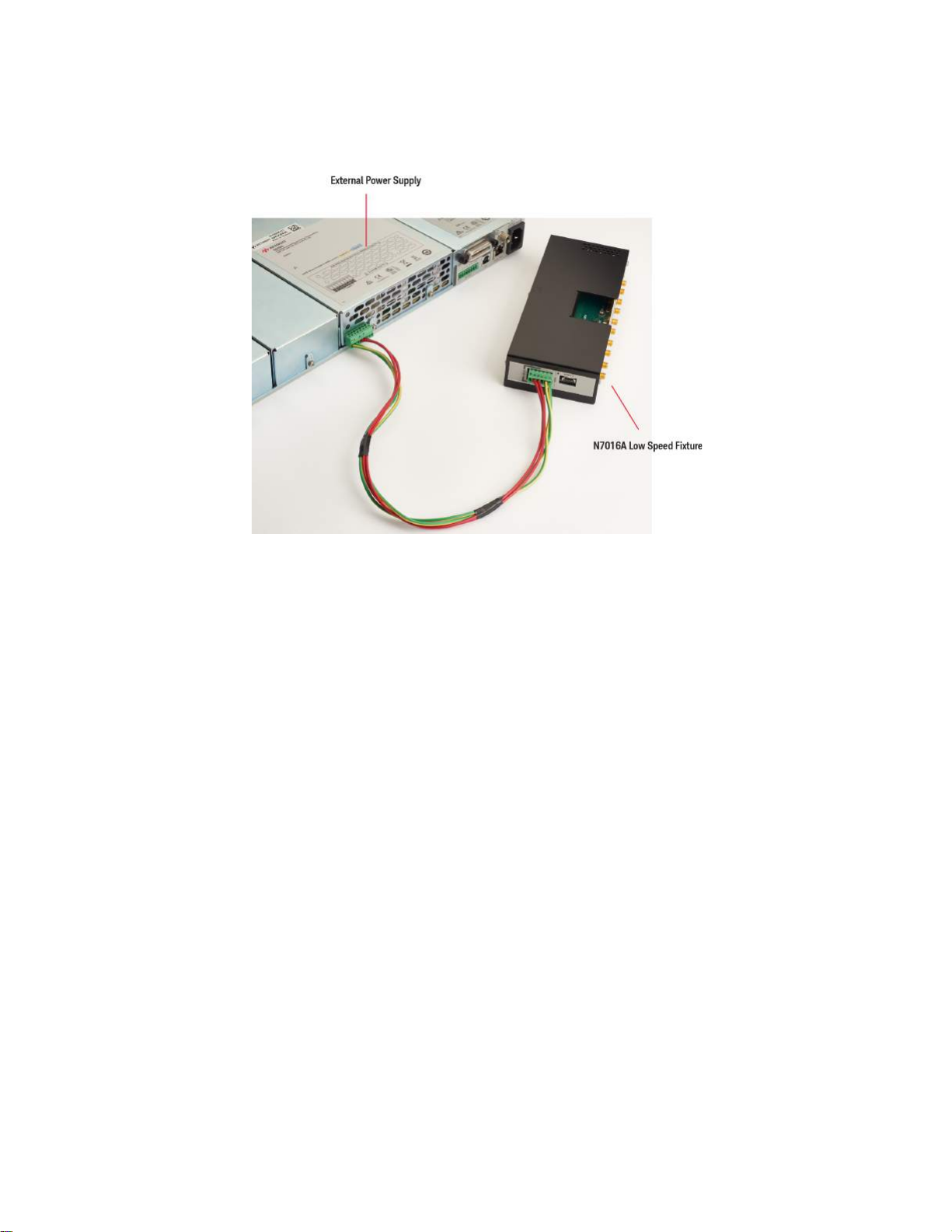
4 N7016A Type-C Low Speed Test Fixture
Figure 5 External Power Supply for Low Speed Fixture
44 Keysight Type-C Connectivity Solution User Guide
Page 45

Replacing the N7016A Fuse
WARNING
When using an external power supply for supplying power to the N7016A, the 6.3A slow blow fuse
protects the DUT from a VBUS to GND short at the external power supply connector.
In case this fuse blows, you can replace this fuse with a fuse (P/N: 2110-0623) provided in the
N7015A/16A Type-C Test Kit.
To replace this fuse, perform the following procedure.
1 Remove the power source and connecting cables from the N7016A.
2 Remove the three screws on the back side and the two screws on the front side of the N7016A
cover using a Torx size 10 driver.
N7016A Type-C Low Speed Test Fixture 4
Do not remove power from the N7016A before disconnecting the
connected devices from Port 1 and Port 2 of this fixture.
Figure 6 Cover Screws
3 Pull the cover off the N7016A.
4 Pull the fuse out carefully and replace this fuse with one of the fuses provided in the N7015A/16A
Type - C Test Kit.
Keysight Type-C Connectivity Solution User Guide 45
Page 46

4 N7016A Type-C Low Speed Test Fixture
Figure 7 Fuse Location
5 After replacing the fuse, carefully fit the cover back on the N7016A and tighten the three screws
on the back side and the two screws on the front side of the N7016A cover (See Figure 6 on
page 45).
46 Keysight Type-C Connectivity Solution User Guide
Page 47

Keysight Type-C Connectivity Solution
User Guide
5 N7017A Type-C Receptacle
Adapter
The N7017A Type-C receptacle adapter allows the N7015A test fixture to act as a receptacle fixture
as well.
The N7015A comes with a plug Type-C connector allowing it to connect only to a USB host/device
with a receptacle connector. But with the usage of the N7017A receptacle adapter, the N7015A can
also connect to a USB device with a plug connector such as a thumb drive.
The N7017A receptacle adapter is required in the following situations:
• Testing tethered devices such as thumb drives
• Enabling Rx signal validation and calibration when testing receptacle devices
The N7017A receptacle adapter provides two receptacle connectors. You can use any of these two
connectors to connect to the N7015A test fixture’s plug and the other to connect to a USB device’s
plug.
Page 48

5 N7017A Type-C Receptacle Adapter
While making these connections, ensure that the A1 pin marking displayed on the receptacle
adapter is aligned to the A1 pin on the N7015A test fixture as shown in the figure below.
To learn more about the pinout of the N7017A’s receptacle connectors, refer to the topic “N7017A
Receptacle Adapter Pinout" on page 101.
To know about the signal path when using the N7017A receptacle adapter with the N7015A test
fixture, refer to the topic “Signal Routing when using the N7017A Receptacle Adapter" on page 102.
This topic illustrates how these signals are routed from the DUT to the N7017A receptacle adapter
and then to the N7015A test fixture.
48 Keysight Type-C Connectivity Solution User Guide
Page 49

Insertion Loss Plot for N7015A with N7017A
N7017A Type-C Receptacle Adapter 5
Keysight Type-C Connectivity Solution User Guide 49
Page 50

5 N7017A Type-C Receptacle Adapter
50 Keysight Type-C Connectivity Solution User Guide
Page 51

Keysight Type-C Connectivity Solution
NOTE
User Guide
6 Recommended Accessories
N2787A 3D Probe Positioner / 51
N2823A or N5448B Coaxial Phase Matched Cable Pair / 51
InfiniiMax 1130B Series Probe Amplifier / 54
E2678B Socketed Head for InfiniiMax Probe / 54
Passive Probe / 54
This chapter lists the accessories that are recommended for use with the Type-C test fixtures. These
accessories provide support, convenience, flexibility, or probing access in your Type-C test setups. You
can order these accessories either with the test fixture(s) or separately later as individual products.
You may want to order the Keysight Type-C Connectivity Core Kit (part number ZA0200) that
includes a number of the recommended accessories and equipment needed for Type-C
testing. See page 12 to know more.
N2787A 3D Probe Positioner
The N2787A 3D Probe Positioner can be quickly positioned in a wide variety of configurations to
support the N7015A and DUT. This support is intended to mitigate accidentally disconnecting the
DUT.
N2823A or N5448B Coaxial Phase Matched Cable Pair
For extending the cable length of the N7015A and to add convenience and flexibility to the probing
setup, use the N2823A 39 inches (1 m) long coaxial phase matched cable pair. This coaxial cable has
2.92 mm male connectors on both ends.
Page 52

6 Recommended Accessories
NOTE
Figure 8 N2823A Coaxial Cable Pair
In situations where a shorter extension of a cable’s length is needed, you
can use the N5448B (25 cm long) coaxial phase matched cable pair.
Figure 9 N5448B Coaxial Cable Pair
The figure below shows the N5448B cables attached to the 2.92 mm high speed signal connectors of
the N7015A test fixture and channels 1 and 3 of the Infiniium oscilloscope.
52 Keysight Type-C Connectivity Solution User Guide
Page 53

Recommended Accessories 6
NOTE
Figure 10 N5448B Cable Pair Attached to N7015A and Infiniium Oscilloscope
The N2823A (or the shorter N5448B) cables provide excellent signal integrity to support high speed
digital signals. These are, therefore, optimum for use with the matched cables for differential high
speed lines of the N7015A Type-C High Speed Test Fixture’s connectivity with the Infiniium
Oscilloscope channels.
Besides this usage, you can also use the N2823A (or the shorter N5448B) cables in other scenarios
such as extending the length of matched cables that connect the high speed signals from the
N7015A to the N7016A or N7018A SMA ports.
To adapt the 2.92mm male connector of the N2823A (or N5448B) cable and
the N7015A test fixture, use the Keysight 3.5mm female-to-3.5mm female
adapter (part number 5061-5311).
This adapter is also recommended to connect the 2.92mm male connector
of these cables to the input of Infiniium V Series, Z Series or 90000X
oscilloscope.
Keysight Type-C Connectivity Solution User Guide 53
Page 54

6 Recommended Accessories
CAUTION
For details on the N2823A and N5448B cables, refer to its guide available in the Document Library
tab of this product’s page on www.keysight.com.
InfiniiMax 1130B Series Probe Amplifier
This InfiniiMax probe amplifier is used for probing USB 2.0 D+/D- or SBU1/SBU2 signals at the
N7016A or N7018A test fixture.
E2678B Socketed Head for InfiniiMax Probe
This socketed head is attached to the 1130B series InfiniiMax probe amplifier for probing USB 2.0
D+/D- or SBU1/SBU2 signals at the N7016A or N7018A test fixture.
The maximum bend radius for the N2823A and N5448B coaxial cable pair is
30 mm. Bending these cables at too tight a radius or twisting the cables can
cause damage, reduce performance, and impact the precision of these
cables.
Also, ensure that the plastic caps that are provided with these cables are
installed when the cables are not in use.
Passive Probe
For probing CC1, CC2, and VBUS signals at the N7016A or N7018A test fixture, use either Keysight
N2871A 200MHz or 10074C 150MHz passive probe.
54 Keysight Type-C Connectivity Solution User Guide
Page 55

Keysight Type-C Connectivity Solution
NOTE
CAUTION
User Guide
7 Sample Setups for Type-C
Testing
Testing a USB 3.1 Host (Tx) / 56
Testing a DisplayPort (2+2) Source (Tx and AUX Channel Testing) / 57
Testing a DisplayPort (4 lanes) Source (Tx and AUX Channel Testing) / 58
Testing a Thunderbolt 3 Host (Tx) / 59
Testing a USB Power Delivery Consumer over Type-C Interface / 60
Testing a USB Power Delivery Provider with N7018A set to Sink Current / 61
Testing a USB Power Delivery Provider over Type-C Interface / 62
This chapter illustrates a few sample setups that utilize the Keysight Type-C connectivity fixtures for
various Type-C interfaces testing scenarios.
As the N7018A is a superset of the features provided by the N7016A plus additional features, the sample
setups illustrated in this chapter utilize the N7018A.
These sample setups are basic setups applicable to a specific testing scenario.
If you are performing compliance testing such as USB 3.1 or DisplayPort source or sink tests,
then refer to the Method of Implementation (MOI) document for the Keysight compliance
software being used to know about the specific setup and equipment requirements for that
compliance testing. The MOI can be downloaded from the webpage of the compliance
software on www.keysight.com.
In addition, the Connect tab of the compliance application software displays the specific
setup requirements for the compliance tests that you want to run. Please follow the
instructions given in this tab.
Ensure that you follow the guidelines and precautions mentioned in the topic “Pre-use
Warnings and Connectivity Precautions" on page 33 while connecting/disconnecting
components used in the test setup.
Page 56

7 Sample Setups for Type-C Testing
Testing a USB 3.1 Host (Tx)
Notes for USB 3.1 Testing Setup
The Rx SMA cables of N7015A connect to the Tx SMA ports of N7018A only in USB 3.1 setups for LFPS signaling.
The TX1/RX1± pair is available for USB 3.1 data transmission if the Type-C connector orientation is selected as Normal (CC1).
The TX2/RX2± pair is available for USB 3.1 data transmission if the Type-C connector orientation is selected as Flipped (CC2).
See page 75 for details.
56 Keysight Type-C Connectivity Solution User Guide
Page 57

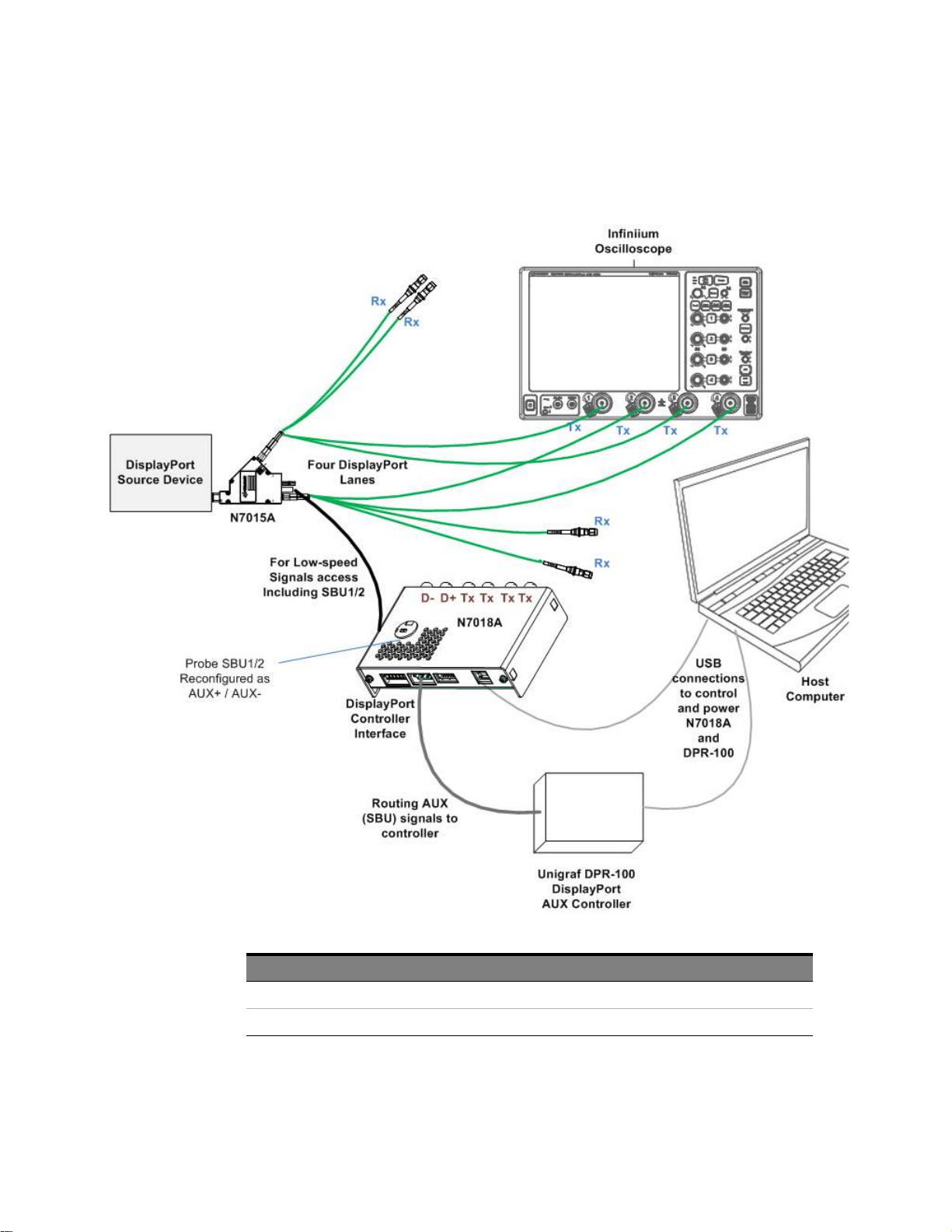
Testing a DisplayPort (2+2) Source (Tx and AUX Channel Testing)
Sample Setups for Type-C Testing 7
Notes for DisplayPort 2+2 Lanes Testing Setup
A DisplayPort Controller such as Unigraf DPR-100 is mandatory in this setup.
The TX1/RX1± pair is available for USB 3.1 data transmission and TX2/RX2± pair is available for DisplayPort transmission if
the Type-C connector orientation is selected as Normal (CC1).
The TX2/RX2± pair is available for USB 3.1 data transmission and TX1/RX1± pair is available for DisplayPort transmission if
the Type-C connector orientation is selected as Flipped (CC2).
See page 75 for details.
Keysight Type-C Connectivity Solution User Guide 57
Page 58
7 Sample Setups for Type-C Testing
Testing a DisplayPort (4 lanes) Source (Tx and AUX Channel Testing)
Notes for DisplayPort 4 Lanes Testing Setup
A DisplayPort Controller such as Unigraf DPR-100 is mandatory in this setup.
Both TX1/RX1± pair and TX2/RX2± pair are available as DisplayPort lanes irrespective of the Type-C connector orientation.
58 Keysight Type-C Connectivity Solution User Guide
Page 59

Testing a Thunderbolt 3 Host (Tx)
Sample Setups for Type-C Testing 7
Notes for Thunderbolt 3 Testing Setup
A Thunderbolt Controller is mandatory in this setup.
Both TX1/RX1± pair and TX2/RX2± pair are available as Thunderbolt lanes irrespective of the Type-C connector orientation.
Keysight Type-C Connectivity Solution User Guide 59
Page 60

7 Sample Setups for Type-C Testing
Testing a USB Power Delivery Consumer over Type-C Interface
Notes for Power Delivery Consumer Testing Setup
To allow the N7018A to act as a PD provider, you must connect the N7018A’s external power source port to an external power supply so that it can meet the power
requirements of the DUT and support high-voltage contracts.
The external power supply wires harness should be set up as per the instructions on page 31.
You must ensure that the external power supply of N7018A is set up and turned on before a Type-C connection is established with the N7018A acting as a Provider.
By default, the N7018A plays the role of a DFP when configured as a PD Provider. However, you can change this role by configuring the N7018A to initiate data role
swap. See page 76 to know more.
60 Keysight Type-C Connectivity Solution User Guide
Page 61

Sample Setups for Type-C Testing 7
Testing a USB Power Delivery Provider with N7018A set to Sink Current
Notes for Power Delivery Provider Testing Setup (with N7018A set to sink current)
To allow the N7018A to act as a PD consumer and sink current, you must connect the N7018A's external power source port to an external power supply.
The external power supply must be set to sink mode (negative current) so that it can sink current during the testing of the DUT.
The external power supply wires harness should be set up as per the instructions on page 31.
You must ensure that the external power supply of N7018A is set up but disabled before a Type-C connection is established with the N7018A acting as a Consumer.
By default, the N7018A plays the role of a UFP when configured as a PD Consumer. However, you can change this role by configuring the N7018A to initiate data
role swap. See page 76 to know more.
Keysight Type-C Connectivity Solution User Guide 61
Page 62

7 Sample Setups for Type-C Testing
Testing a USB Power Delivery Provider over Type-C Interface
Notes for Power Delivery Provider Testing Setup
By default, the N7018A plays the role of a UFP when configured as a PD Consumer. However, you can change this role by
configuring the N7018A to initiate data role swap.
See page 76 to know more.
You must ensure that the power supply of N7018A is disabled and the currents are not drawn before a Type-C connection is
established with the N7018A acting as a Consumer.
62 Keysight Type-C Connectivity Solution User Guide
Page 63

Keysight Type-C Connectivity Solution
User Guide
8 Accessing Type-C Signals
Overview / 64
Probing the CC1, CC2, and VBUS Signals / 65
Probing the SBU1 and SBU2 (Secondary Bus) Signals / 67
Probing the D+ and D- Signals / 70
This chapter describes how to access and probe various Type-C high-speed and low-speed signals when
using the N7015A test fixture with either N7016A or N7017A.
Page 64

8 Accessing Type-C Signals
Overview
Access through...
Signal N7015A N7016A N7018A
High-speed Tx and Rx signals High-speed coax cables of
N7015A connected to an
oscilloscope
Low-speed signals
CC1 / CC2 Signals - CC1 and CC2 probe points on
VBUS Signals - VBUS probe point on N7016A VBUS probe point on N7018A
SBU1 and SBU2 (Secondary Bus) Signals SBU1 and SBU2 test points on
the N7015A
USB 2.0 D+ and D- Signals USB 2.0 D+ and D- cables of
N7015A connected to an
oscilloscope
High-speed coax cables of
N7015A connected to the
N7016A SMA ports for routing
to another DUT connected to
N7016A’s Port2.
N7016A
SBU1 and SBU2 probe points
on top of the N7016A
USB 2.0 D+ and D- probe
points on top of the N7016A
-
CC1 and CC2 probe points on
N7018A
SBU1 and SBU2 probe points
on top of the N7018A
-
The probing procedure for these signals is described in the following sections.
64 Keysight Type-C Connectivity Solution User Guide
Page 65

Probing the CC1, CC2, and VBUS Signals
NOTE
You can probe the CC1, CC2, and VBUS signals either at the N7016A or at the N7018A.
You need passive probes such as Keysight N2871A-3A or 10073D/74D general-purpose high
impedance passive probe with 10:1 attenuation ratio to probe these signals.
Connect the passive probe to the CC1, CC2 and/or VBUS probe points of the N7016A or N7018A as
shown in Figure 2 on page 65.
The GND probe connection points below the CC1, CC2, and VBUS probe
points can be used to clip the probe grounds to the N7016A / N7018A test
fixture.
Accessing Type-C Signals 8
Figure 1 Probing the CC2 signal at the N7018A with the probe ground connected to the GND connection point.
Figure 2 Probing the CC1 signal at the N7016A
Keysight Type-C Connectivity Solution User Guide 65
Page 66

8 Accessing Type-C Signals
Figure 3 Probing the VBUS at the N7018A
66 Keysight Type-C Connectivity Solution User Guide
Page 67

Probing the SBU1 and SBU2 (Secondary Bus) Signals
NOTE
You can probe the USB Type-C SBU1 and SBU2 signals:
• either at the N7015A Type-C test fixture.
• or at the N7016A / N7018A.
Probing the SBU1 and SBU2 Signals at the N7015A Test Fixture
You can probe the SBU1 and SBU2 signals at the N7015A using the E2678B InfiniiMax differential
socket probe head connected to an InfiniiMax probe.
Accessing Type-C Signals 8
Figure 4 Probe connected to the N7015A SBU1/SBU2 differential test point
Probing the SBU1 and SBU2 Signals at the N7016A or N7018A
There are SBU1 and SBU2 probe points available at the top of the N7018A as well as the N7016A.
Using these probe points, you can probe SBU1 and SBU2 signals at the N7016A or N7018A either
Differentially or Single-ended.
The N7018A or N7016A test fixture must be connected to the N7015A via its Type-C
cable for the SBU1/SBU2 signals to be present at these probe points.
Probing the SBU1 and SBU2 Signals Single-ended
For probing the SBU1 or SBU2 signals single-ended, connect the E2678B InfiniiMax differential
socket probe head and an InfiniiMax probe across either the SBU1 or SBU2 pins of the N7018A or the
N7016A test fixture at the probe pins labeled SBU1 or SBU2.
Keysight Type-C Connectivity Solution User Guide 67
Page 68

8 Accessing Type-C Signals
Figure 5 Top Views of the N7018A and N7016A test fixtures showing the Probe Head connected to the SBU2 and
SBU1 Pins Respectively (Single-ended)
Probing the SBU1 and SBU2 Signals Differentially
For probing the SBU1 and SBU2 signals differentially, connect the E2678B InfiniiMax differential
socket probe head and an InfiniiMax probe across both the SBU1 and SBU2 probe pins labeled with
the “+” indicators at the top of the N7018A / N7016A test fixture.
Figure 6 Top view of the N7016A showing the probe head connected to the SBU1 and SBU2 pins differentially
68 Keysight Type-C Connectivity Solution User Guide
Page 69

Accessing Type-C Signals 8
Figure 7 Top view of the N7018A highlighting the SBU1 and SBU2 probe pins and the + indicators for differential
probing
Keysight Type-C Connectivity Solution User Guide 69
Page 70

8 Accessing Type-C Signals
NOTE
NOTE
D+ and D- SMA cables
connected to D+ and D-
ports
Probing the D+ and D- Signals
You can probe the D+ and D- signals differentially:
• either using the D+ and D- pins on the N7016A low speed fixture.
• or connecting the D+ and D- SMA cables of the N7015A to an Oscilloscope.
Using the D+ and D- Pins on the N7016A Low Speed Fixture
1 Connect the E2678B InfiniiMax differential socket probe head and an InfiniiMax probe across both
the D+ and D- pins on the top side of the N7016A low speed fixture.
2 Connect the D+/D- SMA cables of the N7015A to the D+/D- SMA ports on the front of the
N7016A.
Figure 8 Top View of N7016A showing D+ and D- pins and D+/D- SMA cables connected to the D+/D- SMA ports
The N7016A low speed fixture must be connected to the N7015A via both
the Port 1 cable and the D+/D- SMA cables in order for the D+/D- signals to
be present at the N7016A.
There are D+/D- SMA ports on the front of the N7018A to allow the N7018A
to do USB 2.0 data transmission to the DUT via the N7015A. However, the
N7018A does not provide D+/D- probe pins for probing these signals at the
N7018A. If you are using the N7018A and want to monitor D+/D- signals,
then you can do so by connecting the D+/D- SMA cables of the N7015A to
an oscilloscope.
70 Keysight Type-C Connectivity Solution User Guide
Page 71

Keysight Type-C Connectivity Solution
User Guide
9 Installing and Configuring
Software Components for
Type-C Testing
If you are Using N7018A / 72
Installing the N7018A Type-C Test Controller Software / 72
Launching the N7018A Software GUI / 72
Establishing Connectivity between the N7018A Hardware and Software GUI / 74
Setting up the N7018A Emulation Role and ALT Mode and Establishing Connection with DUT / 75
Setting up and Establishing a Power Delivery Contract with DUT / 78
Configuring LFPS Settings (applicable to USB 3.1 testing only) / 82
Viewing the Status of the N7018A Connection with the DUT / 85
If you are Using N7016A / 87
Installing the Appropriate Keysight Compliance Application Software / 92
This chapter describes how to install and configure the software components required for controlling and
configuring the N7018A and N7016A test fixtures covered in this guide.
The chapter includes the software setups needed for N7018A and N7016A. Based on whether you are
using N7018A o N7016A in your testing, follow the steps in the relevant topics in this chapter.
Page 72

9 Installing and Configuring Software Components for Type-C Testing
If you are Using N7018A
If you are using N7018A in your test setup, you need the following software component to configure
and control the N7018A:
N7018A Type-C Test Controller Software
Installing the N7018A Type-C Test Controller Software
Prerequisite
• Before installing the N7018A software, make sure that the Microsoft .NET 4.5.2 software is installed
on your Infiniium Oscilloscope or the host computer used in the test setup.
• If not already installed, download and install the Microsoft .NET 4.5.2 software for free from
https://www.microsoft.com/en-us/download/details.aspx?id=42642. This software requires a few
minutes to install on your Infiniium Oscilloscope or host computer.
Then you can download and install the latest N7018A software from:
http://www.keysight.com/find/N7018A
Follow the on-screen prompts of the Installation wizard to complete the installation. Once the
installation completes, restart the system.
The N7018A software is installed at the following location:
• On a 32-bit system: C:\Program Files (x86)\Keysight\Infiniium\Apps\USB C-Connector\Type-C
Test C ontro l ler
• On a 64-bit system: C:\Program Files\Keysight\Infiniium\Apps\USB C-Connector\Type-C Test
Controller
Launching the N7018A Software GUI
• You can launch the N7018A software GUI by navigating to Start > All Programs > Keysight Infiniium
Applications > Type-C Test Controller.
• Alternatively, you can click Start > Type-C Test Controller.
72 Keysight Type-C Connectivity Solution User Guide
Page 73

Installing and Configuring Software Components for Type-C Testing 9
Figure 9 Startup screen of N7018A Software GUI
Keysight Type-C Connectivity Solution User Guide 73
Page 74

9 Installing and Configuring Software Components for Type-C Testing
NOTE
Establishing Connectivity between the N7018A Hardware and Software GUI
As a first step in configuring the N7018A settings through its software GUI, you connect the software
GUI to the N7018A hardware. This allows you to control and configure the hardware through this
software GUI.
1In the Setup tab of the GUI, click the Connect to Controller button on the top.
The Status should then be displayed as Connected indicating that a connection has been
established between the N7018A hardware and its software GUI.
If you have not connected the N7018A to the oscilloscope or personal
computer on which the N7018A GUI is installed, then the connection
cannot be established and the N7018A status at the top of the GUI is
displayed as “Disconnected”.
74 Keysight Type-C Connectivity Solution User Guide
Page 75

Installing and Configuring Software Components for Type-C Testing 9
NOTE
Setting up the N7018A Emulation Role and ALT Mode and Establishing Connection with DUT
You use the Setup tab in the N7018A software GUI:
• to configure the settings for the emulation role that you want the N7018A to perform in the
Type - C testin g .
• and then to establish N7018A’s Type-C connectivity via N7015A with the link partner under test.
The configuration settings that were last applied to the N7018A hardware
are displayed with their backgrounds highlighted with green in this tab.
When you change these settings and the changes are applied to the
N7018A hardware by clicking Establish Connection, the background
highlighting automatically reflects the changed settings.
1 Select the N7018A Type-C Connector Orientation that you want to use in this test configuration.
This represents the side of the Type-C connector that will be active at the N7015A test fixture.
• Normal (CC1) - Indicates that the CC1 (CC line on the top of the N7018A USB Type-C
connector) will be used as the communication channel.
Keysight Type-C Connectivity Solution User Guide 75
Page 76

9 Installing and Configuring Software Components for Type-C Testing
NOTE
NOTE
NOTE
• Flipped (CC2) - Indicates that the CC2 (CC line on the bottom of the N7018A USB Type-C
connector) will be used as the communication channel.
When testing a USB 3.1 host/device, the selected connector orientation determines whether
USB 3.1 data transmission will be on TX1/RX1+/- pair or TX2 /RX2+/- pair. If CC1 is selected,
then TX1/RX1+/- pair is used for USB 3.1. If CC2 is selected, then TX2/RX2+/- pair is used for
USB 3.1.
As the N7015A Type-C interface cable is reversible, the top side of this
cable connector is provided with a red dot to indicate correct insertion of
the cable into the Type-C port of the N7018A. Inserting this cable with
the red dot facing up allows the N7018A to do proper signal
identification and transmission by matching the lines from the DUT.
For instance, for the “Normal” connector orientation, the N7015A test
fixture should be oriented with the Keysight label facing up and the red
dot on the cable facing up. This means that the upper side of the N7015A
Type-C cable connects to A1 of the N7018A Type-C port.
2From the N7018A Power Role section, select the role that you want the N7018A to perform in the
Power Delivery scenario. At a time, the N7018A can act:
• either as a Power Delivery Source (Provider) to a consumer DUT
• or as a Power Delivery Sink (Consumer) for a provider DUT.
If you configure N7018A as a Power Delivery Provider:
Ensure that the external power supply is able to provide the 5V voltage
for the basic 5V PD contract to be established initially between the
N7018A and DUT once the Type-C connection is established.
If you configure N7018A as a Power Delivery Consumer:
Ensure that the power supply is disabled before establishing connection
between the N7018A and DUT. Do not draw current until the power
delivery contract is established.
3 By default, the N7018A accepts an upstream-facing port (UFP) or a downstream-facing port
(DFP) role based on the power role configured for the N7018A, that is, UFP role when configured
as a Consumer and DFP role when configured as a Provider. This default data role can be
changed when:
76 Keysight Type-C Connectivity Solution User Guide
Page 77

Installing and Configuring Software Components for Type-C Testing 9
NOTE
CAUTION
• the DUT initiates a data role swap. (The N7018A always accepts a data role swap initiated
by DUT.)
• you configure the N7018A to initiate a data role swap itself. To do this, you select the
Initiate swap to DFP / UFP checkbox from the N7018A Data Role section.
There may be situations when the N7018A is not able to complete the
user-configured data role swap successfully. For instance, the DUT may
not support a data role or may not accept the data role swap.
In such situations, you can use the Status bar at the bottom of the GUI to
view the current data role of the N7018A and ascertain whether or not
the data role swap has been successful.
4From the Operating Mode section, choose the ALT mode that you want to test using the N7018A.
The selected mode then becomes the ALT mode to which the N7018A is configured to enter
during testing. By setting different ALT modes from this section, you can achieve integrated
Type-C interfaces testing through a single N7018A connection.
• USB 3.1
• DisplayPort 4 lanes - Four DisplayPort lanes
• DisplayPort 2+2 - Two DisplayPort lanes + two simultaneous USB 3.1 lanes
Based on whether you select 4 lanes or 2+2, there is a change in the supported pin
assignment capabilities of N7018A during the alt-mode discovery process over the
Type-C configuration channel.
• Thunderbolt 3
5 Select the Force SBU Line Reversal checkbox to force a reversal of the standard SBU line routing
when establishing a connection with the DUT. In certain hardware setup configurations, the SBU
lines may be in the wrong orientation for reasons such as the use of a receptacle adapter with the
N7015A and N7018A test setup. In such configurations, this checkbox allows you to bring the
SBU lines in the correct orientation by forcing a reversal.
6 Once you configure the N7018A settings, click the Establish Connection button to establish a
Type-C connection between the N7018A and DUT using the selected CC line.
If a connection already exists, it is disconnected and a new connection is established with the
new settings in the tab.
Prior to changing any power supply settings, DUT configurations, or
disconnecting/connecting a Type-C cable used in the test setup, you
must break the connection established between the N7018A and DUT.
This acts as a safety measure against any damage to the system
components that may occur due to connection/disconnection with the
Type- connection and power supply ON.
You use the Break Connection button to do this.
The Status bar displays whether or not the connection with the DUT is established. In addition, it
also displays if the settings that you configured in the tab are applied to the N7018A hardware.
Keysight Type-C Connectivity Solution User Guide 77
Page 78

9 Installing and Configuring Software Components for Type-C Testing
CAUTION
CAUTION
Setting up and Establishing a Power Delivery Contract with DUT
You use the Power tab in the N7018A GUI to:
• select a Power Data Object (PDO) from the list of DUT’s advertised PDOs.
• negotiate and establish a Power Delivery contract between the N7018A and DUT.
Power Delivery Contract Setup - Flow of Steps
All physical connections must be set up before turning on the power supply to avoid
damage that may result from connecting/disconnecting components with power supply
on.
Make sure the Type-C connection and PD contract is broken before connecting
/disconnecting a Type-C cable between the N7018A/N7015A and DUT.
78 Keysight Type-C Connectivity Solution User Guide
Page 79

Installing and Configuring Software Components for Type-C Testing 9
The section below describes the fields available in the Power tab.
Available Consumer PDOs (DUT) / Available Provider PDOs (DUT)
Based on the currently set power role of the N7018A, either Available Consumer PDOs (DUT) or Available
Provider PDOs (DUT) section is displayed.
The Available Consumer PDOs (DUT) section displays the list of sink PDOs that the power delivery
consumer (DUT) advertised as its power requirements. These represent the power levels at which the
sink (DUT) is able to operate.
The Available Provider PDOs (DUT) section displays the list of source PDOs that the power delivery
provider (DUT) advertised as its power capabilities. These represent the power levels which the
source (DUT) is able to provide.
In these sections, the following values are displayed for each PDO advertised by DUT:
• Min Voltage - The minimum voltage required by the Consumer DUT or provided by the
Provider DUT for a Fixed Supply Type PDO.
• Max Voltage - The maximum voltage required by the Consumer DUT or provided by the
Provider DUT for a Variable or a Battery Supply Type PDO.
Keysight Type-C Connectivity Solution User Guide 79
Page 80

9 Installing and Configuring Software Components for Type-C Testing
NOTE
NOTE
• Max Current - If DUT is the consumer, then the maximum current the DUT may need at the
given voltage range. If DUT is the provider, then the maximum current the DUT can
guarantee to supply at the given voltage range.
• Supply Type - Indicates the type of PDO based on the power supply it exposes. Can be
Fixed, Variable, or Battery.
To set u p a PD con tract
A basic 5V PD contract is automatically established between the N7018A and DUT when you
establish the Type-C connection. After the initial 5V basic PD contract is established, you can select
a PDO from the DUT’s advertised list in the Available PDOs section and set up a new PD contract
with DUT.
1Click the Refresh List button to refresh the list of available PDOs advertised by the DUT. This
allows you to fetch an updated list when you want to set up a new contract.
2 Select the PDO that you want to use by clicking it in the Available PDOs listbox. Click the Select
Target PDO button to choose the currently selected PDO from the Available PDOs list as the
requested PDO with which the N7018A will make PD negotiations with the DUT.
The details of the selected target PDO are then displayed in the Target PDO section.
3 Based on the current power role of the N7018A, either the Consumer PDO to Present or Provider PDO
to Present section is displayed. In this section, specify the details of the N7018A PDO to be
presented to the DUT for PD negotiations. The type of this PDO is always Fixed. When the
N7018A is configured as a Consumer, the voltage that you can specify for this PDO must be
within the voltage range of the target provider PDO.
4Click the Setup New Contract button to set up a new Power Delivery contract between the N7018A
and DUT.
If N7018A is configured as a Power Delivery Provider, the following
popup is displayed to allow you to verify that the external power supply is
set to provide the voltage indicated in the provider PDO to be used for PD
negotiations.
When you click OK on the popup, the existing Type-C connection is
disconnected and a new connection is established first with a minimal 5V
contract and then moved to the new PD contract.
If N7018A is configured as a Power Delivery Consumer, then the existing
Type-C connection is disconnected and a new connection is established
first with the 5V contract and then moved to the new PD contract.
For the consumer DUT, do not draw current prior to the PD contract set
up.
Once the PD contract is set up, the Active Provider PDO and the Active Consumer RDO sections are
auto-populated with the latest details. These sections are auto-refreshed to display the latest details.
80 Keysight Type-C Connectivity Solution User Guide
Page 81

Installing and Configuring Software Components for Type-C Testing 9
• Active Provider PDO - This section displays the PDO that the consumer requested from the
advertised provider PDOs.
• Active Consumer RDO - This section displays the Response Data Object (RDO) that the provider
accepted from the advertised consumer PDOs.
• Operating Current - The amount of current the consumer will need to operate.
• Max Operating Current- The maximum current that the provider should be able to
guaranteer to provide.
Keysight Type-C Connectivity Solution User Guide 81
Page 82

9 Installing and Configuring Software Components for Type-C Testing
NOTE
Configuring LFPS Settings (applicable to USB 3.1 testing only)
You use the LFPS tab to configure the Low Frequency Periodic Signaling (LFPS) settings for N7018A.
You can use the N7018A instead of an external signal pattern generator
such as the Keysight 81134 Pattern Generator to send LFPS signals
pattern to DUT.
1From the Output Enable section, select the N7018A transmission line(s) that you want to enable for
LFPS signaling (LFPS Ping, LFPS Warm Reset, or LFPS Polling patterns). By default, none of the
transmission lines are enabled.
(Ensure that the Rx high-speed cables of N7015A test fixture are connected to the N7018A Tx
line(s) that you enabled in this step.)
2Use the LFPS Ping section to configure and send LFPS Ping bursts to DUT (that is, the
transmission of continuous LFPS signal over a period of defined time).
82 Keysight Type-C Connectivity Solution User Guide
Page 83

Installing and Configuring Software Components for Type-C Testing 9
NOTE
NOTE
NOTE
- N7018A sends out 3 cycles of LFPS with 40ns time period of each cycle.
- N7018A sends an LFPS burst for the total burst time of 120ns.
- N7018A can send an LFPS burst repeatedly (1-32) times depending on
your selection.
- The time between LFPS bursts is set to 200ms.
i In the LFPS Ping section, set the Ping Count. This is the number of times you want the
N7018A to repeat the transmission of the LFPS burst to DUT. Each LFPS ping should
advance the test pattern of the DUT by one CP pattern. With a Gen1 DUT, the patterns
range from CP0-8, and with a Gen2 DUT, the patterns range from CP0-16. The count of
32 allows you to advance from any CP pattern to any other with a single press of the Send
button'
ii Click Send to start the transmission of the LFPS ping burst(s) from N7018A to DUT for the
number of times specified in Ping Count.
iii Click the Warm Reset button to send a continuous burst of LFPS pings for the generation
of a warm reset. A Warm Reset makes a compliant USB3.1 device reset to CP0. It is not
used for a host and will either be ignored or will advance the CP pattern by one count.
For the Warm Reset:
- N7018A sends out a 100ms burst of LFPS.Ping with 40ns time period of
each cycle.
- The tReset is set in the middle of the USB specification to be 100ms of the
Ping.LFPS signal.
3Use the SCD/LBPM section to configure and send SuperSpeedPlus Capability Declaration (SCD)
and SuperSpeedPlus LFPS Based PWM Message (LBPM) patterns associated with LFPS Polling
state to DUT.
The N7018A sends SuperSpeedPlus specific patterns in SCD1 and SCD2 as
follows:
- The SCD1 pattern is fixed at 0010 (LSB is sent first) and can be repeated
1-32 times in a burst depending on the count that you set.
- The SCD2 pattern is fixed at 1101 (LSB is sent first) and can be repeated
1-32 times in a burst depending on the count that you set.
i In the SCD/LBPM section, set the SCD1/2 Count. This is the number of times you want the
N7018A to repeat the transmission of the SCD1 and SCD2 patterns in a burst to DUT.
ii In the LBPM Capability Bytes field, set the number of times you want the N7018A to repeat
the transmission of the LBPM Capability Byte in a burst to DUT.
iii In the Speed section, select the USB speed capability that you want the N7018A to
present in its LBPM Capability Byte. Based on whether you want the N7018A to emulate a
Keysight Type-C Connectivity Solution User Guide 83
Page 84

9 Installing and Configuring Software Components for Type-C Testing
NOTE
a SuperSpeed design (capable of operating at 5Gbps) or a SuperspeedPlus design
(capable of operating at 10Gbps), select the appropriate Gen1 or Gen2 radio button.
iv Click the Enable button to send SCD1/2/LBPM patterns to the DUT. The N7018A
continues to send these patterns until you send an LFPS Ping or Warm Reset or click the
Disable button. (The Enable button changes to Disable after it is clicked)
The transmission of LFPS signals as well as SCD1/2/LBPM signals is done using the same
N7018A transmission lines that you enabled in the LFPS tab. Therefore, at a time, either LFPS
signals or SCD1/2/LBPM signals are enabled for transmission.
.
84 Keysight Type-C Connectivity Solution User Guide
Page 85

Installing and Configuring Software Components for Type-C Testing 9
NOTE
Viewing the Status of the N7018A Connection with the DUT
The Status bar at the bottom of the N7018A displays the current status of the N7018A connection
with the DUT.
The information in the Status bar is auto-refreshed at the time interval of
one and a half seconds.
It displays:
• the current connection status between the N7018A and DUT.
• the ALT mode and data role (DFP/UFP) set for the N7018A in the current connection.
• the CC line used for the connection.
• the power role (provider or consumer) that the N7018A is emulating with DUT.
• the Active PDO (V/A), that is, the PDO selected on the Provider side for the PD contract.
Irrespective of whether the N7018A is emulating a Provider or a Consumer, this PDO always
represents the PDO selected on the Provider side.
• the VBUS: n.nnV and Ext: n.nnV represent the actual voltages of VBUS at the N7018A’s USB
Type-C connector and External Power Supply connector respectively.
Keysight Type-C Connectivity Solution User Guide 85
Page 86

9 Installing and Configuring Software Components for Type-C Testing
86 Keysight Type-C Connectivity Solution User Guide
Page 87

If you are Using N7016A
NOTE
Installing the N7016A Type-C Low Speed Signal Access and Control Fixture Software
Before you Start
Make sure that the Microsoft .NET 4.5.2 software is installed on your Infiniium Oscilloscope or
personal computer before installing the N7016A USB Type-C Low Speed Signal Access and Control
Fixture software.
If not already installed, download and install the Microsoft .NET 4.5.2 software for free from
https://www.microsoft.com/en-us/download/details.aspx?id=42642. This software requires a few minutes to
install on your Infiniium Oscilloscope or personal computer.
Installing and Configuring Software Components for Type-C Testing 9
In case you have not received the installation package of the N7016A
USB Type-C Low Speed Signal Access and Control Fixture software
driver, contact your Keysight representative.
You can also download this software from
http://www.keysight.com/main/software.jspx?ckey=2674876&lc=eng&c
c=US&nid=-33524.1140138&id=2674876.
Install the N7016A USB Type-C Low Speed Signal Access and Control Fixture software by following
the on-screen prompts.
To complete the installation of this software driver on your Infiniium Oscilloscope or personal
computer, restart the system.
Launching the N7016A USB Type-C Low Speed Signal Access and Control Fixture Software
• You can launch this N7016A driver software by navigating to Start > All Programs > Keysight Infiniium
Applications > USB C-Connector > Type-C Interconnect Assembly Controller on your desktop.
• To launch this software for the first time after installation, you can navigate to Start> Type-C
Interconnect Assembly Controller on your desktop.
Keysight Type-C Connectivity Solution User Guide 87
Page 88

9 Installing and Configuring Software Components for Type-C Testing
NOTE
Using the N7016A USB Type-C Low Speed Signal Access and Control Fixture Software
The N7016A USB Type-C Low Speed Signal Access and Control Fixture software is used to configure
the hardware settings of the low speed fixture. To use this software, perform the following procedure.
1 In the Keysight Type C Interconnect Assembly Controller dialog box, click Connect to connect the
N7016A low speed fixture to your Infiniium Oscilloscope or personal computer.
If you have already connected the N7016A low speed fixture hardware to
your Infiniium Oscilloscope or personal computer, this driver software
automatically connects the low speed fixture to the oscilloscope /
computer at the driver software launch.
88 Keysight Type-C Connectivity Solution User Guide
Page 89

Installing and Configuring Software Components for Type-C Testing 9
Keysight Type-C Connectivity Solution User Guide 89
Page 90

9 Installing and Configuring Software Components for Type-C Testing
2 Select the appropriate hardware configuration option in the Keysight Type C Interconnect
Assembly Controller dialog box to configure the N7016A low speed fixture settings. As you
configure these hardware settings, the subsequent actions are logged and displayed in the
bottom section of the software driver dialog box.
90 Keysight Type-C Connectivity Solution User Guide
Page 91

Installing and Configuring Software Components for Type-C Testing 9
3Click Write settings to hardware to allow the configured hardware settings to take effect.
Keysight Type-C Connectivity Solution User Guide 91
Page 92

9 Installing and Configuring Software Components for Type-C Testing
Installing the Appropriate Keysight Compliance Application Software
For compliance testing, you need to install the appropriate Keysight compliance application software
in addition to the N7018A / N7016A controller software.
These applications are integrated with the N7016A as well as N7018A software. Therefore,
irrespective of whether you are using N7016A or N7018A, the compliance applications can be easily
used.
The description of these compliance software GUIs is outside the scope of this guide. You can find
the compliance application software at www.keysight.com. You can download its Methods of
Implementation (MOI) document to get a description of all the compliance tests, how to configure
and run these tests, and how to analyze the results obtained.
92 Keysight Type-C Connectivity Solution User Guide
Page 93

Keysight Type-C Connectivity Solution
User Guide
10 Schematic Diagrams and
Pinouts
N7015A Dimensions / 94
N7015A Pinout / 95
N7018A Dimensions / 98
N7017A Receptacle Adapter Dimensions / 100
N7017A Receptacle Adapter Pinout / 101
Signal Routing when using the N7017A Receptacle Adapter / 102
Page 94

10 Schematic Diagrams and Pinouts
N7015A Dimensions
94 Keysight Type-C Connectivity Solution User Guide
Page 95

N7015A Pinout
Schematic Diagrams and Pinouts 10
The tables that follow provide the pinouts for the connectors of the N7015A test fixture.
Pin Details
Connector Name
J1 SBU1
SBU2
Top Coax/Bottom Coax
Connector Name
J2 RX2+
J3 RX2-
J4 TX2+
J5 TX2-
Top Coax/Bottom Coax
Connector Name
J6 TX1-
J7 TX1+
J8 RX1-
J9 RX1+
Connector Name
J10 D-
J11 D+
J12 (Looking into the Connector)
Pin No. Name Name Pin No.
A1 GND GND B12
A2 NC NC B11
A3 NC NC B10
A4 VBUS VBUS B9
A5 CC1 SBU2 B8
A6 NC NC B7
Keysight Type-C Connectivity Solution User Guide 95
Page 96

10 Schematic Diagrams and Pinouts
J12 (Looking into the Connector)
Pin No. Name Name Pin No.
A7 NC NC B6
A8 SBU1 CC2 B5
A9 VBUS VBUS B4
A10 NC NC B3
A11 NC NC B2
A12 GND GND B1
96 Keysight Type-C Connectivity Solution User Guide
Page 97

J13 (Looking into the Connector)
Pin No. Name Name Pin No.
B1 GND GND A12
B2 TX2+ RX2+ A11
B3 TX2- RX2- A10
B4 VBUS VBUS A9
B5 CC2 SBU1 A8
B6 D- A7
B7 D+ A6
B8 SBU2 CC1 A5
B9 VBUS VBUS A4
B10 RX1- TX1- A3
B11 RX1+ TX1+ A2
Schematic Diagrams and Pinouts 10
B12 GND GND A1
Keysight Type-C Connectivity Solution User Guide 97
Page 98

10 Schematic Diagrams and Pinouts
N7018A Dimensions
98 Keysight Type-C Connectivity Solution User Guide
Page 99

N7016A Dimensions
Schematic Diagrams and Pinouts 10
Keysight Type-C Connectivity Solution User Guide 99
Page 100

10 Schematic Diagrams and Pinouts
N7017A Receptacle Adapter Dimensions
All dimensions are in Inches.
100 Keysight Type-C Connectivity Solution User Guide
 Loading...