

Keysight Technologies PXIe Series, M9502A AXIe, AXIe Series, M9005A PXIe, M9010A PXIe Troubleshooting Manual
...Page 1

Troubleshooting Guide
Diagnose and Resolve PXIe and AXIe Chassis Communication Problems
Keysight PXIe/AXIe Chassis
M9005A PXIe Chassis M9502A AXIe Chassis
M9010A PXIe Chassis M9505A AXIe Chassis
M9018B PXIe Chassis M9514A AXIe Chassis
M9019A PXIe Chassis
Page 2

Page 3

Notices
© Keysight Technologies, Inc. 2018
No part of this manual may be reproduced in any form or by any means
(including electronic storage and retrieval
or translation into a foreign language)
without prior agreement and written consent from Keysight Technologies, Inc. as
governed by United States and international copyright laws.
Manual Part Number
M9019-90005
Edition
First Edition, November 2018
Published in USA
Keysight Technologies, Inc.
1400 Fountaingrove Parkway
Santa Rosa, CA 95403 USA
Trademarks
AXIe is a registered trademark of the AXIe
Consortium.
PXI is a registered trademark of the PXI
Systems Alliance.
®
PICMG
AdvancedTCA
marks of the PCI Industrial Computer
Manufacturers Group.
PCI-SIG
registered trademarks of PCI-SIG.
Thunderbolt and the Thunderbolt logo
are trademarks of Intel Corporation or its
subsidiaries in the U.S. and/or other
countries.
, Compact PCI®, and
®
are registered trade-
®
, PCI Express®, and PCIe
®
are
Sales and Technical Support
To contact Keysight for sales and technical support, refer to the support links on
the following Keysight websites:
www.keysight.com/find/assist (world-
wide contact information for repair and
service)
Declaration of Conformity
Declarations of Conformity for this product and for other Keysight products may
be downloaded from the Web. Go to
http://keysight.com/go/conformity and
click on “Declarations of Conformity.” You
can then search by product number to
find the latest Declaration of Conformity.
Technology Licenses
The hard ware and/or software described
in this document are furnished under a
license and may be used or copied only in
accordance with the terms of such
license.
Warranty
THE MATERIAL CONTAINED IN THIS
DOCUMENT IS PROVIDED “AS IS,” AND
IS SUBJECT TO BEING CHANGED,
WITHOUT NOTICE, IN FUTURE EDITIONS. FURTHER, TO THE MAXIMUM
EXTENT PERMITTED BY APPLICABLE
LAW, KEYSIGHT DISCLAIMS ALL WARRANTIES, EITHER EXPRESS OR IMPLIED,
WITH REGARD TO THIS MANUAL AND
ANY INFORMATION CONTAINED
HEREIN, INCLUDING BUT NOT LIMITED
TO THE IMPLIED WARRANTIES OF MERCHANTABILITY AND FITNESS FOR A
PARTICULAR PURPOSE. KEYSIGHT
SHALL NOT BE LIABLE FOR ERRORS OR
FOR INCIDENTAL OR CONSEQUENTIAL
DAMAGES IN CONNECTION WITH THE
FURNISHING, USE, OR PERFORMANCE
OF THIS DOCUMENT OR OF ANY INFORMATION CONTAINED HEREIN. SHOULD
KEYSIGHT AND THE USER HAVE A SEPARATE WRITTEN AGREEMENT WITH
WARRANTY TERMS COVERING THE
MATERIAL IN THIS DOCUMENT THAT
CONFLICT WITH THESE TERMS, THE
WARRANTY TERMS IN THE SEPARATE
AGREEMENT SHALL CONTROL.
Keysight Technologies does not warrant
third-party system-level (combination of
chassis, controllers, modules, etc.) performance, safety, or regulatory compliance unless specifically stated.
DFARS/Restricted Rights
Notices
If software is for use in the performance
of a U.S. Government prime contract or
subcontract, Software is delivered and
licensed as “Commercial computer software” as defined in DFAR 252.227-7014
(June 1995), or as a “commercial item” as
defined in FAR 2.101(a) or as “Restricted
computer software” as defined in FAR
52.227-19 (June 1987) or any equivalent
agency regulation or contract clause.
Use, duplication or disclosure of Software
is subject to Keysight Technologies’ standard commercial license terms, and nonDOD Departments and Agencies of the
U.S. Government will receive no greater
than Restricted Rights as defined in FAR
52.227-19(c)(1-2) (June 1987). U.S. Government users will receive no greater
than Limited Rights as defined in FAR
52.227-14 (June 1987) or DFAR 252.2277015 (b)(2) (November 1995), as applicable in any technical data.
Page 4

Page 5

Contents
Introduction . . . . . . . . . . . . . . . . . . . . . . . . . . . . . . . . . . . . . . . . . . . . . . . . . . . . . 7
Understand the system hardware connections . . . . . . . . . . . . . . . . . . . . . . . . . 7
Host Controllers . . . . . . . . . . . . . . . . . . . . . . . . . . . . . . . . . . . . . . . . . . . . . . . 7
Remote Controller and System Interface Module . . . . . . . . . . . . . . . . . . 7
Embedded Controller . . . . . . . . . . . . . . . . . . . . . . . . . . . . . . . . . . . . . . . . 9
Chassis Backplane . . . . . . . . . . . . . . . . . . . . . . . . . . . . . . . . . . . . . . . . . . . . . 9
PXIe Chassis Backplane and Supported Module Types . . . . . . . . . . . . . . 9
AXIe Chassis Backplane and Module Layouts . . . . . . . . . . . . . . . . . . . . . . . 10
Understand the Software Components . . . . . . . . . . . . . . . . . . . . . . . . . . . . . . 12
Required Keysight IO Libraries Suite . . . . . . . . . . . . . . . . . . . . . . . . . . . . . . 12
Required System Firmware and Software Drivers . . . . . . . . . . . . . . . . . . . . 12
Chassis Firmware. . . . . . . . . . . . . . . . . . . . . . . . . . . . . . . . . . . . . . . . . . . 12
Chassis Software Driver . . . . . . . . . . . . . . . . . . . . . . . . . . . . . . . . . . . . . 13
Module Firmware. . . . . . . . . . . . . . . . . . . . . . . . . . . . . . . . . . . . . . . . . . . 13
Module Software Drivers. . . . . . . . . . . . . . . . . . . . . . . . . . . . . . . . . . . . . 13
Guidelines to Diagnose and Resolve Communication Problems . . . . . . . . . . . 14
Avoid Bent Pins. . . . . . . . . . . . . . . . . . . . . . . . . . . . . . . . . . . . . . . . . . . . . . . 14
Use Supported Host Controllers . . . . . . . . . . . . . . . . . . . . . . . . . . . . . . . . . 14
Setup Applications with Recommended and Supported Configurations . . 15
Power-up the Chassis First . . . . . . . . . . . . . . . . . . . . . . . . . . . . . . . . . . . . . 15
Ensure LEDs are Lit Correctly on System Module . . . . . . . . . . . . . . . . . . . 15
Lower Transfer Rate Settings to Ensure Reliability . . . . . . . . . . . . . . . . . . . 15
Make Sure All Required Software Drivers are Installed. . . . . . . . . . . . . . . . 16
System Module Driver Needs to be Installed in PC Configuration. . . . . 17
Install Controller Driver in Embedded Controller Configuration . . . . . . 17
Use Updated Keysight IO Libraries Suite. . . . . . . . . . . . . . . . . . . . . . . . . . . 18
Use Updated Firmware and Software Drivers . . . . . . . . . . . . . . . . . . . . . . . 19
Avoid Overheating the Chassis. . . . . . . . . . . . . . . . . . . . . . . . . . . . . . . . . . . 19
Summary . . . . . . . . . . . . . . . . . . . . . . . . . . . . . . . . . . . . . . . . . . . . . . . . . . . . . . 20
Keysight PXI/AXIe Chassis Troubleshooting Guide v
Page 6

vi Keysight PXI/AXIe Chassis Troubleshooting Guide
Page 7

PXI/AXIe Chassis Troubleshooting Guide
Introduction
Keysight PXIe and AXIe chassis are the backbone of a PXIe or AXIe system. These
chassis have high performance backplanes providing PXI and AXIe modules the
ability to communicate rapidly with one another and the controller. It is
important to make sure the chassis and modules enumerate correctly before any
system control takes place. This paper helps you understand the hardware
connections, the firmware and software components of the system, and gives
guidelines on how to diagnose and resolve chassis communication problems.
Understand the system hardware connections
PXIe and AXIe chassis systems consist of the chassis itself plus other related
modules, such as host controllers, system modules, and the instrument modules
which are installed in the chassis backplane. Understanding the hardware
connections will help you verify if there are any hardware issues in the system.
Host Controllers
The computer that controls the chassis is known as the host controller or system
controller. The host controller can be either a remote controller or an embedded
controller.
Remote Controller and System Interface Module
A remote controller can be a desktop personal computer (PC) or a rack mounted
PC.
- For Keysight PXIe chassis, except the M9005A, the remote controller connects
to the chassis with a Keysight M9048A, M9048B, or M9049A Host Adapter
PCIe Interface module (desktop adapter) installed in the PC, through a PCIe
cable to an M9022A, M9023A, or M9024A PXIe System Interface Module
installed in slot 1 of the chassis. The M9021A is supported only in the M9018A
and M9018B. It will provide a Gen2 link when connected to an M9048A.
- The M9005A PXIe chassis comes with an integrated system module in the
chassis. Option 002 must be ordered with the chassis and adds a PCIe
Desktop adapter for the M9005A and a 3 meter cable to connect to the PC.
Other desktop adapters, such as the M9048A, and embedded controllers,
such as the M9037A, are not supported in this chassis.
- The M9502A 2-Slot and M9505A 5-Slot AXIe chassis come with an embedded
system module (ESM) while the M9514A chassis uses the M9521A AXIe
System Module (ASM) in the chassis to communicate and control the chassis.
7
Page 8

Understand the system hardware connections
The ESM/ASM also has a LAN connection to use for chassis communication (i.e.
chassis firmware updates, web interface to monitor/control the chassis, etc.).
However, a LAN connection does not provide communication with individual
AXIe modules. You will need to use PCIe to control the AXIe modules instead. In
addition, if an AXIe instrument module supports USB, you can use a USB cable
to connect the AXIe chassis to the host via the ESM with the USB option. A PCIe
interface card/cable is not required for this configuration to control the AXIe
modules.
Figures 1 and 2 below show two of the many configurations that can be setup
with the PXIe and AXIe chassis system. Figure 3 shows the recommended LAN
connection if you want to use LAN to communicate with the AXIe chassis.
Figure 1 Use the M9048A with the M9021A in the M9018B (x8 Gen2) or M9048B with the M9022A
in all PXIe chassis (x8 Gen3 cable link). Chassis link depends on the chassis capability
Figure 2 Use either the M9048A with the M9502A or M9505A (x8 Gen2) and M9048B with the
M9521A/M9514A (x8 Gen2)
8 Keysight PXI/AXIe Chassis Troubleshooting Guide
Page 9

Understand the system hardware connections
Figure 3 Recommended LAN Connections for AXIe System
Embedded Controller
An embedded controller, such as Keysight’s M9037A PXIe Embedded Controller,
is a small form-factor, Windows-based PC designed for installation in the system
controller slot 1 of the chassis. An embedded controller consumes two or three
expansion slots to the left of the PXIe chassis slot 1. In an AXIe chassis, the
embedded controller, such as the M9537A AXIe Embedded Controller, is
installed in slot 1.
Chassis Backplane
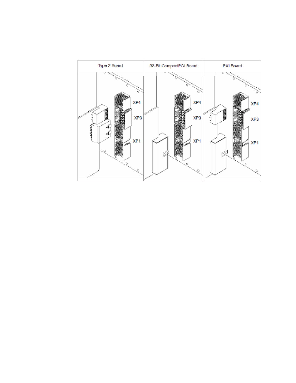
PXIe Chassis Backplane and Supported Module Types
Keysight PXIe chassis backplanes support different type of modules. This gives
the system designer flexibility to mix and match the number and location of PXIe
and hybrid-compatible modules. The hybrid slots support the three types of
boards shown below in Figure 4. A Type 2 board connects to both XP4, which
contains the PXIe instrumentation signals, and XP3, which contains the PCIe
signals. A 32-bit CompactPCI board connects to only the CompactPCI signals. A
PXI board connects to both the XP4 (PXI instrumentation signals) and the
CompactPCI signals. Refer to the PXIe chassis user guide and the Keysight PXIe
Chassis Interactive Block Diagram for detail of the pin-outs.
Keysight PXI/AXIe Chassis Troubleshooting Guide 9
Page 10
Understand the system hardware connections
Figure 4 PXIe Hybrid Slots Detail
AXIe Chassis Backplane and Module Layouts
Keysight AXIe chassis are fully compatible with the AXIe 1.0 specification. Figures
6 and 7 below show the chassis backplane, with modules removed from all slots.
The backplane provides Zone 1 connector J10 and Zone 2 connectors P20, P21,
P22, P23, P24. Connector designations are shown for instrument slot 1. The
M9502A backplane differs from the M9505A in that the 2-slot backplane does
not use P22. A typical module layout is shown below the backplane photos, with
the mating connectors J20 through J24 and P10. Depending on module type,
the module may implement all or none of J20-J24. Connector P10 is required to
power the module. Refer to the AXIe chassis’ user guide for pin-out details.
10 Keysight PXI/AXIe Chassis Troubleshooting Guide
Page 11

Understand the system hardware connections
Zone 2 Zone 1
Instrument Slot 2
Logical Slot 3
Instrument Slot 1
Logical Slot 2
ESM Slot
Logical Slot 1
Zone 2 Zone 1
Instrument Slot 5
Logical Slot 6
Instrument Slot 4
Logical Slot 5
Instrument Slot 3
Logical Slot 4
Instrument Slot 2
Logical Slot 3
Instrument Slot 1
Logical Slot 2
ESM Slot
Logical Slot 1
Figure 5 M9502A AXIe Backplane Connector Layout
Figure 6 M9505A AXIe Backplane Connector Layout
Keysight PXI/AXIe Chassis Troubleshooting Guide 11
Page 12

Understand the Software Components
To control the hardware components of the PXIe or AXIe chassis system, system
firmware must be up-to-date in the hardware. Keysight’s IO Libraries Suite and
software drivers need to be installed on the host controller. The following details
describe the software components required to communicate with the PXIe or
AXIe chassis system.
Required Keysight IO Libraries Suite
Keysight’s IO Libraries Suite is a collection of libraries and utilities that enable
you to connect your chassis to the host controller and run programs on the host
controller that interact with the chassis and modules. The IO Libraries Suite is
used with all Keysight instruments and is not specific to the PXIe or AXIe chassis.
Download the latest version from: www.keysight.com/find/iosuite. Remember to
always install IO Libraries Suite before
Also, always use the latest version of the IO Libraries Suite to avoid any
compatibility issues.
Understand the Software Components
installing any instrument driver software.
Required System Firmware and Software Drivers
It is important to understand the firmware (installed in the PXIe or AXIe chassis or
module) and the software driver (installed in the host controller) components in
order to troubleshoot the system. Having knowledge of these components help
you determine if there are any control issues in the system. The following
paragraphs describe the control components in a PXIe or AXIe system.
Both chassis and instrument module firmware and software driver version
information can be viewed in the Soft Front Panel (SFP) About dialog menu bar by
clicking Help
and software driver components are shown in the product user guides. The
revision history can be viewed at the product firmware and software driver
update websites.
Chassis Firmware
The chassis firmware is part of the chassis and controls the chassis lower-level
hardware components. Every chassis comes from the factory with firmware
installed in it. Firmware files contain multiple files for controlling various
components in the chassis. If any of these components are missing or not
updated to be compatible with the software drivers, communication issues may
result. The latest firmware and installation instructions are always available on
the product’s Keysight web page. Keysight recommends that you always use the
latest, most up-to-date firmware.
About or through the product’s IVI drivers. Details of the firmware
12 Keysight PXI/AXIe Chassis Troubleshooting Guide
Page 13

Understand the Software Components
Chassis Software Driver
The chassis software driver is the component that lets the host controller
operating system communicate and control the chassis. The driver, specific to
the chassis you are controlling, needs to be installed in the host controller to
communicate with the chassis. If the chassis driver is missing or not updated to
be compatible with the firmware, communication issues may result. Drivers are
often supplied with each chassis on a CD. The latest drivers are always available
on the product’s Keysight web page. Keysight recommends that you always use
the latest, most up-to-date drivers.
Module Firmware
Like the chassis, the module firmware is part of the module and controls the
module’s lower-level hardware components. Every module comes from the
factory with firmware installed on it. If a module’s firmware is missing or out of
date, communication issues may result. The latest firmware (if any) and
installation instructions are always available on the product’s Keysight web page.
Keysight recommends that you always use the latest, most up-to-date firmware.
Module Software Drivers
Every PXI or AXIe instrument module, including Embedded Controllers such as
the M9037A or M9537A, also needs to have its driver software installed on the
host controller. If any module’s software drivers are missing or out of date,
communication issues may result. A missing system module driver can cause
inconsistent and/or incomplete chassis enumeration. Drivers are often supplied
with each module on a CD. The latest drivers are always available on the
product’s Keysight web page. Keysight recommends that you always use the
latest, most up-to-date drivers.
Keysight PXI/AXIe Chassis Troubleshooting Guide 13
Page 14

Guidelines to Diagnose and Resolve Communication Problems
Guidelines to Diagnose and Resolve Communication Problems
Setting up a PXIe or AXIe system can be complicated since the system consists
of so many different components. You might experience communication and
control issues in the system if these components are not set up correctly. Follow
the guidelines and tips below for details of how to diagnose and resolve some
common communication issues. If the following guidelines do not help resolve
your issue, please contact www.keysight.com/find/contactus for further help
with setting up your system.
Avoid Bent Pins
The chassis backplane connectors contain hundreds of pins. These pins mate
with the sockets on the module when you slide the module into the chassis.
When you first insert the module, you insert it between the top and bottom rails.
As you slide the module in, the side of the connectors touch to further align the
module's connector over the pins. The final push to insert the module seats the
pins tightly in the connectors.
Be aware that misuse can result in bent pins. If a chassis backplane has a single
bent pin, it is possible that the damage is limited to one slot. However, a bent pin
can touch an adjacent pin, causing an electrical short that further damages all
slots in the chassis. The impact of a bent pin can range from none, to subtle, to
severe. A bent pin can cause unpredictable behavior in the chassis and the
instruments. It can be very difficult to determine the root cause of this erratic
behavior. Refer to the product’s user guides for methods to avoid bent pins.
Use Supported Host Controllers
Check the PC Tested Configurations with PXI/AXIe Chassis document
(www.keysight.com/find/PXIAXIeTestedPC) for a list of host controllers tested to
be compatible with the PXIe or AXIe chassis. Keysight can support only
configurations with host controllers that are listed in this document. Keysight
cannot guarantee other controllers outside of this list will work for your
application. Check back on the list often as Keysight updates the list when newer
supported models are available. Contact www.keysight.com/find/contactus if
you must use a computer that is not listed on the list.
14 Keysight PXI/AXIe Chassis Troubleshooting Guide
Page 15

Guidelines to Diagnose and Resolve Communication Problems
Setup Applications with Recommended and Supported Configurations
There are many configurations you can create to setup a proper PXIe or AXIe
system. Refer to the Interface Modules and Adapters for PXIe and AXIe Systems
Data Sheet (https://literature.cdn.keysight.com/litweb/pdf/5992-0377EN.pdf)
for other examples of recommended and supported configurations. You can also
use the Multi-Chassis Designer Tool (www.keysight.com/find/pxie-multichassis)
to check if your configuration is supported.
Power-up the Chassis First
Always power up all chassis before booting the PC if you are using an external
PC. An embedded PC will power-up correctly if using a single chassis, but slave
chassis must be powered-up first. If you are connecting multiple chassis
together, consider using the multi-chassis power sequencing capability built into
many of Keysight’s chassis.
Ensure LEDs are Lit Correctly on System Module
If you are using the M902xA system modules in the PXIe system with PC
configuration, ensure the status LEDs are lit and are the correct color for your
given configuration. The status LEDs tell you the status of the module, the link
connection, and the backplane connection. There are also a series of LEDs across
the top and bottom of the system modules indicating power and configuration.
Refer to the PXIe System Modules and Cable Interface Installation Guide
(www.keysight.com/upload/cmc_upload/All/SystemModuleInstallationGuide.pdf)
for details of how to diagnose connection issues with these LEDs.
Lower Transfer Rate Settings to Ensure Reliability
Sometimes a device cannot correctly follow the PCIe training protocol and the
link fails to connect reliably. As a workaround or diagnostics debug step, you can
use the DIP switches on the system modules to lower the maximum negotiated
PCIe speed to Gen1. This lower speed may allow your device to function reliably.
Refer to the PXIe System Modules and Cable Interface Installation Guide for
instructions on setting the DIP switches.
Keysight PXI/AXIe Chassis Troubleshooting Guide 15
Page 16

Guidelines to Diagnose and Resolve Communication Problems
Make Sure All Required Software Drivers are Installed
Every hardware component in the system must have the software drivers
installed for the operating system to communicate with them. This includes the
chassis, system module and any other modules installed on the chassis
backplane. You can use the host controller’s Windows Device Manager to verify
that the chassis and modules are installed correctly. Figure 7 below shows
example of a typical multi-chassis PXIe system setup.
Figure 7 Device Manager View of a Typical Multi-Chassis PXIe System Setup
16 Keysight PXI/AXIe Chassis Troubleshooting Guide
Page 17

Guidelines to Diagnose and Resolve Communication Problems
System Module Driver Needs to be Installed in PC Configuration
The system module driver must be installed when setting up the PXIe or AXIe
system. The Desktop Adapter module does not require a driver and it cannot be
seen in the Device Manager. However, the System Module is like all other
modules connected on the chassis backplane – it needs its driver to
communicate with the chassis. Without this driver, you will not be able to see the
chassis or its installed modules on the system in Windows Device Manager.
Make sure the System Module driver is installed in the host controller. Refer to
the System Module web page to install this driver.
Install Controller Driver in Embedded Controller Configuration
Typically, when you purchase an embedded controller, it is delivered with the
embedded controller driver installed. However, if you re-image the controller
with your own version of the operating system, you need to reinstall this driver to
get your system to work properly. Refer to the embedded controller websites to
install this driver.
Keysight PXI/AXIe Chassis Troubleshooting Guide 17
Page 18

Guidelines to Diagnose and Resolve Communication Problems
Use Updated Keysight IO Libraries Suite
As products are updated, the IO libraries components need to be updated as well
to support these products. To make sure all the chassis and modules show up
correctly, the IO libraries need to be updated. You can download and install the
latest version of the IO libraries at www.keysight.com/find/iolib. Figure 8 below
shows the Keysight Connection Expert (KCE) view of a typical multi-chassis PXIe
system setup. Note that if your chassis and modules are not identified correctly
in Device Manager, then KCE will not be able to configure the system and may
have missing components or miss-numbered chassis.
Figure 8 Keysight Connection Expert View of a Typical Multi-Chassis PXIe System Setup
18 Keysight PXI/AXIe Chassis Troubleshooting Guide
Page 19

Guidelines to Diagnose and Resolve Communication Problems
Use Updated Firmware and Software Drivers
Often the firmware and software driver bits for the chassis and the modules need
to be updated to support continuous improvements. Use the most up-to-date
release of these two to ensure they are compatible with each other and support
the latest functionality available in the hardware. Refer to the product’s firmware
and software drivers update websites to install the latest versions of these bits.
Avoid Overheating the Chassis
Module temperatures in a system can impact operation. It’s important to actively
manage the environment inside your chassis. Refer to the Keysight PXIe Chassis
Cooling Guidelines white paper
(https://literature.cdn.keysight.com/litweb/pdf/5992-3270EN.pdf) for details on
protecting your PXIe chassis from overheating. Refer to the AXIe chassis user
guide for similar guidelines for the AXIe chassis.
Keysight PXI/AXIe Chassis Troubleshooting Guide 19
Page 20

Summary
Summary
As you can see, many different factors affect the communications and control of
a PXIe or AXIe system. After understanding the hardware connections, knowing
the firmware and software components of the system, and following the
guidelines provided, you will be able to diagnose and resolve common chassis
communication problems. Remember to take these into account when setting up
your PXIe or AXIe system to use in your application.
1 Check that all modules are installed correctly in the chassis.
2 Always power-up the chassis first then power-up the controller.
3 If using an external host controller, make sure the correct LEDs are lit and are
the correct color.
4 Confirm the host controller’s Windows Device Manager properly identifies all
chassis and modules.
5 If Device Manager has not correctly identified every component, check to
make sure the drivers are installed for the missing components.
6 If Device Manager has not correctly identified every component, lower the
transfer rate settings to Gen1.
7 Check Keysight Connection Expert to see if all components are identified and
correctly labeled/numbered.
8 If there are errors in Keysight Connection Expert, ensure the system module
driver is loaded.
9 Open the Soft Front Panel for each module and perform a self-test if the
module has one.
10 Ensure the latest driver is being used and firmware is up-to-date.
11 If using AXIe, you can also use the chassis web interface to see if the modules
are listed. The chassis health menu is also useful to ensure the cards are
operating correctly and there are no errors.
20 Keysight PXI/AXIe Chassis Troubleshooting Guide
Page 21

Page 22

This information is subject to change
without notice
© Keysight Technologies 2018
Published in USA
First Edition, November 2018
*M9019-90005*
M9019-90005
www.keysight.com
 Loading...