

Page 1

User Guide
M9010A, M9018B, M9019A
Keysight PXIe Chassis Family
Page 2

Page 3

Notices
© Keysight Technologies, Inc. 2018
No part of this manual may be reproduced in any form or by any means
(including electronic storage and retrieval
or translation into a foreign language)
without prior agreement and written consent from Keysight Technologies, Inc. as
governed by United States and international copyright laws.
Manual Part Number
M9019-90003
Edition
Fourth Edition, August 2018
Published by
Keysight Technologies, Inc.
900 S. Taft Ave.
Loveland, CO 80537 USA
Trademarks
PICMG®, Compact PCI® are registered
trademarks of the PCI Industrial Computer Manufacturers Group.
PCI-SIG
registered trademarks of PCI-SIG.
LabVIEW is a registered trademark of
National Instruments
®
, PCI Express®, and PCIe
®
are
Sales and Technical Support
To contact Keysight for sales and technical support, refer to the support links on
the following Keysight websites:
www.keysight.com/find/M9010A
www.keysight.com/find/M9018B
www.keysight.com/find/M9019A
(product-specific information and support, software and documentation
updates)
www.keysight.com/find/assist (world-
wide contact information for repair and
service)
Declaration of Conformity
Declarations of Conformity for this product and for other Keysight products may
be downloaded from the Web. Go to
http://keysight.com/go/conformity and
click on “Declarations of Conformity.” You
can then search by product number to
find the latest Declaration of Conformity.
Technology Licenses
The hard ware and/or software described
in this document are furnished under a
license and may be used or copied only in
accordance with the terms of such
license.
Warranty
THE MATERIAL CONTAINED IN THIS
DOCUMENT IS PROVIDED “AS IS,” AND
IS SUBJECT TO BEING CHANGED,
WITHOUT NOTICE, IN FUTURE EDITIONS. FURTHER, TO THE MAXIMUM
EXTENT PERMITTED BY APPLICABLE
LAW, KEYSIGHT DISCLAIMS ALL WARRANTIES, EITHER EXPRESS OR IMPLIED,
WITH REGARD TO THIS MANUAL AND
ANY INFORMATION CONTAINED
HEREIN, INCLUDING BUT NOT LIMITED
TO THE IMPLIED WARRANTIES OF MERCHANTABILITY AND FITNESS FOR A
PARTICULAR PURPOSE. KEYSIGHT
SHALL NOT BE LIABLE FOR ERRORS OR
FOR INCIDENTAL OR CONSEQUENTIAL
DAMAGES IN CONNECTION WITH THE
FURNISHING, USE, OR PERFORMANCE
OF THIS DOCUMENT OR OF ANY INFORMATION CONTAINED HEREIN. SHOULD
KEYSIGHT AND THE USER HAVE A SEPARATE WRITTEN AGREEMENT WITH
WARRANTY TERMS COVERING THE
MATERIAL IN THIS DOCUMENT THAT
CONFLICT WITH THESE TERMS, THE
WARRANTY TERMS IN THE SEPARATE
AGREEMENT SHALL CONTROL.
Keysight Technologies does not warrant
third-party system-level (combination of
chassis, controllers, modules, etc.) performance, safety, or regulatory compliance unless specifically stated.
DFARS/Restricted Rights
Notices
If software is for use in the performance
of a U.S. Government prime contract or
subcontract, Software is delivered and
licensed as “Commercial computer software” as defined in DFAR 252.227-7014
(June 1995), or as a “commercial item” as
defined in FAR 2.101(a) or as “Restricted
computer software” as defined in FAR
52.227-19 (June 1987) or any equivalent
agency regulation or contract clause.
Use, duplication or disclosure of Software
is subject to Keysight Technologies’ standard commercial license terms, and nonDOD Departments and Agencies of the
U.S. Government will receive no greater
than Restricted Rights as defined in FAR
52.227-19(c)(1-2) (June 1987). U.S. Government users will receive no greater
than Limited Rights as defined in FAR
52.227-14 (June 1987) or DFAR 252.2277015 (b)(2) (November 1995), as applicable in any technical data.
iii
Page 4

Safety Information
The following general safety precautions must be observed during all
phases of operation of this instrument.
Failure to comply with these precautions or with specific warnings or operating instructions in the product
manuals violates safety standards of
design, manufacture, and intended use
of the instrument. Keysight Technologies assumes no liability for the customer's failure to comply with these
requirements.
General
Do not use this product in any manner not
specified by the manufacturer. The protective features of this product must not be
impaired if it is used in a manner specified in
the operation instructions.
Before Applying Power
Verify that all safety precautions are taken.
Make all connections to the unit before
applying power. Note the external markings
described under “Safety Symbols”.
Ground the Instrument
Keysight chassis’ are provided with a
grounding-type power plug. The
instrument chassis and cover must be
connected to an electrical ground to
minimize shock hazard. The ground pin
must be firmly connected to an electrical ground (safety ground) terminal at
the power outlet. Any interruption of
the protective (grounding) conductor
or disconnection of the protective
earth terminal will cause a potential
shock hazard that could result in personal injury.
PXIe Chassis are for indoor use only.
Mains supply voltage fluctuations must
not exceed
ply voltage.
Transient overvoltages typically present on the Mains supply (installation
CAT II)
Do Not Operate in an Explosive
Atmosphere
Do not operate in the presence of
flammable gases or fumes.
Do Not Operate Near Flammable
Liquids
Do not operate the module/chassis in
the presence of flammable liquids or
near containers of such liquids.
±10% of the nominal sup-
Cleaning
Clean the outside of the Keysight module/chassis with a soft, lint-free,
slightly dampened cloth. Do not use
detergent or chemical solvents.
Do Not Remove Instrument Cover
Only qualified, service-trained personnel who are aware of the hazards
involved should remove instrument
covers. Always disconnect the power
cable and any external circuits before
removing the instrument cover.
Keep away from live circuits
Operating personnel must not remove
equipment covers or shields. Procedures involving the removal of covers
and shields are for use by servicetrained personnel only. Under certain
conditions, dangerous voltages may
exist even with the equipment
switched off. To avoid dangerous electrical shock, DO NOT perform procedures involving cover or shield removal
unless you are qualified to do so.
DO NOT operate damaged
equipment
Whenever it is possible that the safety
protection features built into this product have been impaired, either through
physical damage, excessive moisture,
or any other reason, REMOVE POWER
and do not use the product until safe
operation can be verified by servicetrained personnel. If necessary, return
the product to a Keysight Technologies
Sales and Service Office for service and
repair to ensure the safety features are
maintained.
DO NOT block the primary
disconnect
The primary disconnect device is the
appliance connector/power cord when
a chassis used by itself, but when
installed into a rack or system the disconnect may be impaired and must be
considered part of the installation.
Do Not Modify the Instrument
Do not install substitute parts or perform any unauthorized modification to
the product. Return the product to a
Keysight Sales and Service Office to
ensure that safety features are maintained.
In Case of Damage
Instruments that appear damaged or
defective should be made inoperative
and secured against unintended operation until they can be repaired by
qualified service personnel.
Do NOT block vents and fan exhaust:
To ensure adequate cooling and ventilation, leave a gap of at least 50mm
(2") around vent holes on both sides of
the chassis.
Do NOT operate with empty slots: To
ensure proper cooling and avoid damaging equipment, fill each empty slot
with an AXIe filler panel module.
Do NOT stack free-standing chassis:
Stacked chassis should be rackmounted.
All modules are grounded through the
chassis: During installation, tighten
each module's retaining screws to
secure the module to the chassis and
to make the ground connection.
Operator is responsible to maintain
safe operating conditions. To ensure
safe operating conditions, modules
should not be operated beyond the full
temperature range specified in the
Environmental and physical specification. Exceeding safe operating conditions can result in shorter lifespan,
improper module performance and
user safety issues. When the modules
are in use and operation within the
specified full temperature range is not
maintained, module surface temperatures may exceed safe handling conditions which can cause discomfort or
burns if touched. In the event of a
module exceeding the full temperature
range, always allow the module to cool
before touching or removing modules
from the chassis.
iv
Page 5

Page 6

vi
Page 7

Contents
1 Introduction to the PXIe Chassis
Key Chassis Features . . . . . . . . . . . . . . . . . . . . . . . . . . . . . . . . . . . . . . . . . . . . . 12
Front Panel Trigger Ports . . . . . . . . . . . . . . . . . . . . . . . . . . . . . . . . . . . . . . . 13
Interactive Block Diagram . . . . . . . . . . . . . . . . . . . . . . . . . . . . . . . . . . . . . . . . . 14
Chassis Maintenance and Inspection . . . . . . . . . . . . . . . . . . . . . . . . . . . . . . . . 17
Static-safe Handling Procedures . . . . . . . . . . . . . . . . . . . . . . . . . . . . . . . . . 18
Terminology. . . . . . . . . . . . . . . . . . . . . . . . . . . . . . . . . . . . . . . . . . . . . . . . . . 19
System or Cable Interface Modules . . . . . . . . . . . . . . . . . . . . . . . . . . . . . . . . . 20
Using the M9021A PCIe Cable Interface Module with the M9018A/B . . . . 20
Installing PXI Modules in the Chassis . . . . . . . . . . . . . . . . . . . . . . . . . . . . . . . . 21
Avoiding Bent Pins . . . . . . . . . . . . . . . . . . . . . . . . . . . . . . . . . . . . . . . . . . . . 23
Methods to avoid bent pins . . . . . . . . . . . . . . . . . . . . . . . . . . . . . . . . . . . 23
Periodic chassis inspection . . . . . . . . . . . . . . . . . . . . . . . . . . . . . . . . . . . 24
How to inspect your chassis backplane for bent pins or debris . . . . . . . 24
What to do if you find a bent pin. . . . . . . . . . . . . . . . . . . . . . . . . . . . . . . 24
Keysight PXIe Chassis Family User Guide vii
Page 8

Chassis Front Panel LEDs . . . . . . . . . . . . . . . . . . . . . . . . . . . . . . . . . . . . . . . 25
Related Documentation. . . . . . . . . . . . . . . . . . . . . . . . . . . . . . . . . . . . . . . . . . . 27
Using the M9018A Chassis with the PXIe Chassis Family Driver . . . . . . . . . . . 28
Additional changes from the M9018A to the M9018B. . . . . . . . . . . . . . . . . 29
Driver Behavior . . . . . . . . . . . . . . . . . . . . . . . . . . . . . . . . . . . . . . . . . . . . . . . 29
Summary . . . . . . . . . . . . . . . . . . . . . . . . . . . . . . . . . . . . . . . . . . . . . . . . . 29
Chassis Related Products and Accessories. . . . . . . . . . . . . . . . . . . . . . . . . . . . 31
2 PXIe Chassis Management Capabilities
Summary of Chassis Management Capabilities . . . . . . . . . . . . . . . . . . . . . . . . 34
Using the Soft Front Panel to Configure Chassis Parameters . . . . . . . . . . . . . 34
The Chassis Alarm Architecture. . . . . . . . . . . . . . . . . . . . . . . . . . . . . . . . . . . . . 35
3 Chassis and Host Controller Power Up or Down Sequence
Methods of powering up the chassis . . . . . . . . . . . . . . . . . . . . . . . . . . . . . . 38
Power Up Sequencing . . . . . . . . . . . . . . . . . . . . . . . . . . . . . . . . . . . . . . . . . 39
Power Down Sequencing . . . . . . . . . . . . . . . . . . . . . . . . . . . . . . . . . . . . . . . 39
Performing a System Power Cycle . . . . . . . . . . . . . . . . . . . . . . . . . . . . . . . . . . 40
Performing a Chassis Hard Reset. . . . . . . . . . . . . . . . . . . . . . . . . . . . . . . . . 41
4 Chassis Alarm Architecture
Power-on Default Alarm Thresholds . . . . . . . . . . . . . . . . . . . . . . . . . . . . . . . . . 44
Events Which Re-establish the Power-on Default Thresholds . . . . . . . . . . . . . 47
Relationship Between Alarm Occurred and the Front Panel LEDs. . . . . . . . . . 47
Soft Front Panel Alarm Thresholds . . . . . . . . . . . . . . . . . . . . . . . . . . . . . . . . 48
5 Power Supply Operation
Power Supply Capacity . . . . . . . . . . . . . . . . . . . . . . . . . . . . . . . . . . . . . . . . . . . 50
Temperature Derating of the Primary Power Module . . . . . . . . . . . . . . . . . 50
Power Calculator Spreadsheet . . . . . . . . . . . . . . . . . . . . . . . . . . . . . . . . . . . 50
Over Temperature Protection . . . . . . . . . . . . . . . . . . . . . . . . . . . . . . . . . . . . 52
Over-current Protection . . . . . . . . . . . . . . . . . . . . . . . . . . . . . . . . . . . . . . . . 52
Short Circuit Protection . . . . . . . . . . . . . . . . . . . . . . . . . . . . . . . . . . . . . . . . 53
Internal Fuses . . . . . . . . . . . . . . . . . . . . . . . . . . . . . . . . . . . . . . . . . . . . . . . . 53
Internal Fans . . . . . . . . . . . . . . . . . . . . . . . . . . . . . . . . . . . . . . . . . . . . . . . . . 53
Front Panel Power LED. . . . . . . . . . . . . . . . . . . . . . . . . . . . . . . . . . . . . . . . . 53
Measuring the Main Voltage Rails Directly . . . . . . . . . . . . . . . . . . . . . . . . . . . . 54
Monitoring the Power Supply Rails . . . . . . . . . . . . . . . . . . . . . . . . . . . . . . . 54
6 Chassis Cooling and Rack Mounting
Overview of chassis cooling . . . . . . . . . . . . . . . . . . . . . . . . . . . . . . . . . . . . . 59
viii Keysight PXIe Chassis Family User Guide
Page 9

Monitoring the Chassis Temperature . . . . . . . . . . . . . . . . . . . . . . . . . . . . . . . . 61
Monitoring Chassis Fan Speeds . . . . . . . . . . . . . . . . . . . . . . . . . . . . . . . . . . . . 67
Setting the Fan Speed vs. Chassis Temperature Profile . . . . . . . . . . . . . . . 67
Default Minimum Fan Speed Threshold Limit . . . . . . . . . . . . . . . . . . . . . . . 67
Rack Mounting the Chassis. . . . . . . . . . . . . . . . . . . . . . . . . . . . . . . . . . . . . . . . 75
Rack Mount Accessory Kits . . . . . . . . . . . . . . . . . . . . . . . . . . . . . . . . . . . . . 76
7 10 MHz Reference Clock Source
8 Configuring the PXI Trigger Bus
Chassis Trigger Lines. . . . . . . . . . . . . . . . . . . . . . . . . . . . . . . . . . . . . . . . . . . . . 84
Trigger Bus Segments . . . . . . . . . . . . . . . . . . . . . . . . . . . . . . . . . . . . . . . . . 85
Trigger Line Reservations and Routing . . . . . . . . . . . . . . . . . . . . . . . . . . . . 85
Persistent Versus Volatile Reservations . . . . . . . . . . . . . . . . . . . . . . . . . . . 87
Example: Persistent Versus Volatile Reservations . . . . . . . . . . . . . . . . . 87
Configuring PXI Trigger Bus Connections . . . . . . . . . . . . . . . . . . . . . . . . . . 88
Front Panel Trigger Ports . . . . . . . . . . . . . . . . . . . . . . . . . . . . . . . . . . . . . . . 89
Trigger Port capability as a function of the firmware version . . . . . . . . . . . 89
Trigger Port capability using Trigger Bridge 2018 firmware . . . . . . . . . . . . 92
Front Panel Trigger Port Configuration Guidelines. . . . . . . . . . . . . . . . . . . . . . 96
Using KtMTrig Trigger Manager IVI Driver . . . . . . . . . . . . . . . . . . . . . . . . . . . 101
Installation Requirements . . . . . . . . . . . . . . . . . . . . . . . . . . . . . . . . . . . . . 101
Supported Operating Systems:. . . . . . . . . . . . . . . . . . . . . . . . . . . . . . . 101
Shared Components . . . . . . . . . . . . . . . . . . . . . . . . . . . . . . . . . . . . . . . 101
VISA.NET . . . . . . . . . . . . . . . . . . . . . . . . . . . . . . . . . . . . . . . . . . . . . . . . 101
Uninstall. . . . . . . . . . . . . . . . . . . . . . . . . . . . . . . . . . . . . . . . . . . . . . . . . 102
9 Multiple Chassis Operation
Multiple Chassis Power Sync . . . . . . . . . . . . . . . . . . . . . . . . . . . . . . . . . . . . . 106
Power Sync Cabling . . . . . . . . . . . . . . . . . . . . . . . . . . . . . . . . . . . . . . . . . . 108
Power Sync and Other Features. . . . . . . . . . . . . . . . . . . . . . . . . . . . . . . . . 109
Chassis Rear Panel Inhibit Switch. . . . . . . . . . . . . . . . . . . . . . . . . . . . . 109
Wake on LAN Signal . . . . . . . . . . . . . . . . . . . . . . . . . . . . . . . . . . . . . . . 109
Wake on PCIe . . . . . . . . . . . . . . . . . . . . . . . . . . . . . . . . . . . . . . . . . . . . 109
Remote Power On with M9022A, M9023A, M9024A . . . . . . . . . . . . . . 109
Power Sync with Multiple PXIe Chassis . . . . . . . . . . . . . . . . . . . . . . . . . . . . . 110
Connect Multiple PXIe or AXIe Chassis Together with a Single Controller? . 111
10 PCIe Link Configuration
Changing and Restoring the M9018 PCIe Switch Fabric Configuration . . . . 115
Selecting a Link Configuration . . . . . . . . . . . . . . . . . . . . . . . . . . . . . . . . . . 117
Additional Fabric Information . . . . . . . . . . . . . . . . . . . . . . . . . . . . . . . . 119
Keysight PXIe Chassis Family User Guide ix
Page 10

Using the PCIe Switch Fabric Configurator program. . . . . . . . . . . . . . . . . 120
Configuring the chassis to run at Gen 1 speeds . . . . . . . . . . . . . . . . . . . . 129
Reconfiguration failure . . . . . . . . . . . . . . . . . . . . . . . . . . . . . . . . . . . . . . . . 130
Restoring operation after an interruption of the configuration process . . 130
Restoring the Factory Default 1x8 Base Configuration . . . . . . . . . . . . . . . . . 131
11 Chassis Maintenance
Chassis Firmware and Revision . . . . . . . . . . . . . . . . . . . . . . . . . . . . . . . . . . . . 140
Viewing the Chassis Revision Information Using the SFP . . . . . . . . . . . . . 140
Viewing the Chassis Revision Information Using the IVI Drivers . . . . . . . . 141
Updating Chassis Firmware. . . . . . . . . . . . . . . . . . . . . . . . . . . . . . . . . . . . . . . 141
Chassis Backplane Switches . . . . . . . . . . . . . . . . . . . . . . . . . . . . . . . . . . . . . . 142
Performing a Chassis Self Test . . . . . . . . . . . . . . . . . . . . . . . . . . . . . . . . . . . . 144
Performing Self Test using the Soft Front Panel . . . . . . . . . . . . . . . . . . . . 144
Performing Self Test using the IVI Drivers . . . . . . . . . . . . . . . . . . . . . . . . . 145
Self Test Codes and Messages . . . . . . . . . . . . . . . . . . . . . . . . . . . . . . . . . . 146
1 Index
x Keysight PXIe Chassis Family User Guide
Page 11

PXIe Chassis Family
User Guide
1 Introduction to the PXIe Chassis
Keysight provides three PXIe chassis in the PXIe Chassis Family:
– M9010A – a Gen 3, 24 GB/s,10-Slot PXI chassis
(www.keysight.com/find/M9010A)
– M9018B – a Gen 2, 8GB/s, 18-Slot PXI chassis
(www.keysight.com/find/M9018B)
– M9019A – a Gen 3, 24 GB/s, 18-Slot PXI chassis
(www.keysight.com/find/M9019A)
The PXIe chassis is the backbone of a PXIe system. These chassis have a high
performance backplane providing PXI modules in the chassis the ability to
communicate rapidly with one another and to PC. It also provides power and
cooling for the modules.
The PXIe Chassis Family Driver supports five PXIe Chassis including the M9010A,
M9018A, M9018B, M9019A, and M9043A. The M9018A is now discontinued, but
still fully supported by the PXIe Chassis Family Driver. The M9018B is a drop-in
replacement for the M9018A. The M9043A is only available as part of a Keysight
solution. The M9043A has all the features of the M9019A plus an integrated High
Frequency Reference clock. The High Frequency Reference clock features match
those found in the M9300A, thus providing all the M9300A features without
consuming a module slot.
For information on using M9018A, refer to the user documentation
available at www.keysight.com/find/M9018A. For information
regarding using the PXIe Family Chassis Driver with the M9018A,
see “Using the M9018A Chassis with the PXIe Chassis Family
Driver” on page 28.
It is assumed that you have turned on the chassis system,
installed the Keysight IO Libraries Suite, the chassis drivers, and
the chassis Soft Front Panel. The Keysight PXIe Chassis Family
Startup Guide provides step-by-step guidance on turning on the
chassis system.
11
Page 12

Introduction to the PXIe Chassis Key Chassis Features
Key Chassis Features
The Keysight family of PXIe chassis is designed for easy integration into large
systems containing multiple PXIe chassis and other, non-PXI instrumentation.
The Keysight PXIe chassis have these key features:
– Up to 16 PXIe hybrid slots (the M9010A has 8 hybrid slots), 1 PXIe timing
slot, and 1 PXIe system slot.
– 4U chassis with innovative cooling design.
– Ultra high performance PCIe interface
-- The M9010A has Gen 3 PCIe with a two-link (x8, x16) system slot and x8
links to the hybrid/timing slots.
-- The M918B provides configurable 2-Link (2x8) and 4-Link (4x4) plus
M9021A configuration (1x8).
-- The M9019A provides Gen 3 PCIe with a two-link (x8, x16) system slot
and x8 links to the hybrid/timing slots.
– High data bandwidth (maximum 24 GB/s system and 8 GB/s slot-to-slot).
– Multi-chassis power-sequencing using rear panel RJ-45 connectors.
– Front panel external trigger input/output ports.
– One common driver supports IVI-C and IVI.NET for all three chassis (and
the M9018A PXIe chassis).
Figure 1 shows a front view of the M9019A chassis. The M9018B chassis is
similar; the M9010A chassis is similar but has ten slots.
Figure 1 Keysight M9019A PXIe Chassis Front and Side View (The other chassis are similar)
12 Keysight PXIe Chassis Family User Guide
Page 13

Key Chassis Features Introduction to the PXIe Chassis
The following figure shows the M9019A chassis rear panel. The M9018B chassis
rear panel is similar; the M9010A chassis has two fans.
Figure 2 Keysight M9019A PXIe Chassis Rear and Side View (The other chassis are similar)
Front Panel Trigger Ports
Two front panel SMB trigger connectors connect to the PXI [0:7] backplane
trigger bus in Trigger Bus Segment 1 and 2 in the M9010A chassis and Trigger
Bus Segments 1, 2 and 3 in the M9018B and M9019A chassis. For information on
using these two trigger ports, see “Front Panel Trigger Ports” on page 89.
Figure 3 Chassis Front Panel Trigger Ports (M9019A shown)
Make certain that your test system application is not running when
you reconfigure these two trigger ports. Reconfiguring the ports
may cause an unexpected pulse on the trigger port lines.
Keysight PXIe Chassis Family User Guide 13
Page 14

Introduction to the PXIe Chassis Interactive Block Diagram
Interactive Block Diagram
An interactive Block Diagram exists for all three chassis. This Block Diagram is
usable for training and understanding how the chassis works. You can download
the block diagram from:
www.keysight.com/find/pxi-blockdiagram
The Block Diagram and other information is available on the individual the web
pages of the three PXIe chassis:
www.keysight.com/find/M9010A
www.keysight.com/find/M9018B
www.keysight.com/find/M9019A
14 Keysight PXIe Chassis Family User Guide
Page 15

Chassis (Static) Block Diagram
Figure 4 Chassis (Static) Block Diagram
Keysight PXIe Chassis Family Startup Guide 15
Page 16

16 Keysight PXIe Chassis Family Startup Guide
Page 17

Chassis Maintenance and Inspection Introduction to the PXIe Chassis
Chassis Maintenance and Inspection
These chassis are Safety Class 1 Products (provided with a
protective earthing ground incorporated in the power cord).
The mains plug shall only be inserted in a socket outlet
provided with a protective earth contact. Any interruption
of the protective conductor inside or outside of the product
is likely to make the product dangerous. Intentional
interruption is prohibited. Inspect the protective conductor
periodically to ensure that it is uninterrupted.
- No operator serviceable parts inside. Refer servicing to
qualified personnel.
- To prevent electrical shock, do not remove covers.
- To prevent electrical shock, disconnect the chassis power
cord before cleaning. Use a dry cloth or one slightly
dampened with water to clean the external case parts. Do not
attempt to clean internally.
No periodic maintenance of the chassis is required. However, Keysight
recommends monitoring the Primary Power Module (PPM) voltage rails, the
chassis fan speeds, and the chassis firmware an ongoing basis:
– Power supply voltages —The power supply voltages (5 Vdc, 5 Vaux, 12 Vdc,
and –12 Vdc) should all be within ±5% (10% for 3.3 Vdc) of their nominal
values. Keysight recommends checking the power rails at least yearly. The
power rails are accessible on the rear panel DB-9 connector. See
“Measuring the Main Voltage Rails Directly” on page 54.
–Fan speeds —The chassis has fans located at the rear of the chassis. A low
fan speed possibly indicates that a fan is wearing out or a fan blade is
partially obstructed. Keysight recommends using the chassis Soft Front
Panel to check the fan speeds yearly as well. See “Monitoring Chassis Fan
Speeds” on page 67.
– Chassis firmware — Keysight recommends that you periodically check to see
if there is a chassis firmware revision available that is later than your
chassis firmware revision. If so, it is suggested that you download and
install the latest firmware revision available as described in “Updating
Chassis Firmware” on page 141.
If a power supply voltage is out of tolerance or a fan speed is low, see the
Keysight PXIe Family Chassis Service Guide for diagnostic information and
troubleshooting tips.
Keysight PXIe Chassis Family User Guide 17
Page 18

Introduction to the PXIe Chassis Chassis Maintenance and Inspection
The weight of an empty M9018B or M9019A PXIe chassis (no
modules installed in the chassis) is approximately 29.8 lbs (13.5
kg). Lift the chassis using a single side handle only when the
total chassis weight (chassis plus installed modules) does not
exceed 75 lbs (34.0 kg). Otherwise use both side handles to lift
the chassis.
The M9010A chassis weighs 30.91 lbs (14.02 kg).
Installing modules in the chassis may increase its weight to a
point where two people are required to lift the chassis. If two
people are not available, use a mechanical lift to lift the chassis.
The chassis should be transported using a rolling cart.
Static-safe Handling Procedures
Electrostatic discharge (ESD) can
damage or destroy electronic
components. Use a static-safe work
station to perform at work on electronic
assemblies. The figure shows a
static-safe work station using two types
of ESD protection:
- Conductive table-mat and wrist-strap
combination
- Conductive floor-mat and heel-strap
combination
Both types, when used together, provide a significant level of ESD protection. Of
the two, only the table-mat and wrist-strap combination provides adequate ESD
protection when used alone. To ensure user safety, the static-safe accessories
must provide at least 1 MΩ of isolation from ground.
DO NOT use these techniques for a static-safe work station when
working on circuitry with a voltage potential greater than 500
volts.
18 Keysight PXIe Chassis Family User Guide
Page 19

Chassis Maintenance and Inspection Introduction to the PXIe Chassis
Terminology
The combination of the chassis, the host controller (and a PCIe cable if the host
controller is a remote controller), and the chassis I/O software running on the
host controller is referred to as a chassis system. The computer that controls the
chassis is known as the host controller or system controller, and is shown at the
top of the hierarchy in the following figure.
Figure 5 System Controller Types
The host controller can either be a remote controller or an embedded controller.
A remote controller can be a desktop PC or a rack mounted PC. The remote
controller interfaces to the chassis with an M9048B or M9049A Host Adapter
PCIe Interface modules (desktop adapter) installed in the PC, through a PCIe
cable to an M9022A, M9023A, or M9024A PXIe System Interface Module
installed in slot 1 of the chassis. The M9048A and M9021A can be used with the
M9018A and M9018B chassis in Gen 2 mode.
An embedded controller, such as the Keysight M9037A Embedded Controller, is a
small form-factor, Windows-based PC that is designed for installation in the
system controller slot of the chassis (slot 1). An embedded controller consumes
two or three expansion slots to the left of chassis slot 1.
For a PC to serve as a remote controller, its BIOS must enumerate
all the PCIe slots in the chassis. Many computers cannot
enumerate a sufficient number of PCIe slots and may not work for
your configuration.
Keysight provides the document Tested PC and PXI/AXIe Chassis
Configurations, which lists the embedded, desktop and
rack-mounted PCs that have been verified to enumerate the PCIe
slots in the PXIe chassis. Use this document, available under the
Document Library tab at www.keysight.com/find/pxi-chassis, to
guide your selection of remote controller PCs.
Keysight PXIe Chassis Family User Guide 19
Page 20

Introduction to the PXIe Chassis System or Cable Interface Modules
Note: Ensure the
M9018A/B
backplane switch is
in the right-hand
position when using
the M9021A.
System or Cable Interface Modules
Make certain that you install the driver software for the M9022A, M9023A, or
M9024A System Interface Modules. The M9021A Cable Interface module does
not require a software driver.
Keysight’s M9021A Cable Interface module can operate only with
the 1x8 switch fabric found on the M9018A and M9018B chassis.
The M9021A cannot be used with the M9010A and M9019A
chassis - use the M9022A, M9023A, or M9024A System Interface
Modules with any Keysight PXIe chassis.
Using the M9021A PCIe Cable Interface Module with the M9018A/B
The M9021A PCIe Cable Interface module does not derive power from the
chassis connector used by PXI embedded controllers. Instead, the modules use
the top connector on the chassis backplane for its 3.3V and 12V power.
However, a switch on the M9018A and M9018B chassis backplane must be set to
supply those voltages to the connector.
The default position of the switch is to the left and does not supply the voltages
to the connector. To use the M9021A Cable Interface module in Slot 1 of either
chassis, you must move the slide switch to the right before installing the module.
Figure 6 M9018A/B Backplane Switch
Note: Setting this switch is not required for the M9022A, M9023A, or M9024A.
20 Keysight PXIe Chassis Family User Guide
Page 21

Installing PXI Modules in the Chassis Introduction to the PXIe Chassis
Installing PXI Modules in the Chassis
Recommended best practices to ensure proper and safe module operating
conditions:
PXI hardware does not support “hot-swap” (changing modules
while the chassis is powered on) capabilities. Before installing or
removing a module into/from the chassis, power off the chassis
to prevent damage to modules.
– Ensure proper chassis airflow is maintained
– Select a chassis that provides thermal protection if fans become
inoperable or forced air cooling is obstructed
– Use slot blockers (Keysight Y1212A) and EMC filler panels (Keysight
Y1213A) in empty module slots to ensure proper operating temperatures.
The Keysight Y1214B Air Inlet kit (not for M9010A use) supplies additional
cooling air from the front of the chassis. These accessories optimize
module temperature performance and reliability of test system.
– Monitor the chassis temperatures and fan speeds to determine a balance
of fan noise and cooling performance.
– Do not disable fans. Position chassis to allow plenty of space around
chassis air intake and fan exhaust.
– Place the chassis in a horizontal position such as in a rack or on a bench.
– At environment temperatures above 45°C, set chassis fan speed to high.
The M9018B and M9019A chassis have multiple air intakes located at the lower
sides, lower front, and chassis bottom. Do not block the air intakes or fan
exhausts.
The M9010A chassis has two fans that pull air from the rear of the chassis and
exhausts it out the front and top. Do not block the air intakes or fan exhausts.
Inserting modules into the chassis when it is in a vertical position
increases the possibility of bend ing pins on the backplane and
permanently damaging the chassis. It is recommended that you
insert modules only with the chassis in a horizontal position,
such as in a rack or on a bench. Once the modules are inserted
and secured, the chassis may be used in a vertical position.
However, before moving the chassis to the vertical position,
install all the blanking plates to prevent debris falling onto the
chassis and getting lodged in the backplane connectors.
Keysight PXIe Chassis Family User Guide 21
Page 22

Page 23

Installing PXI Modules in the Chassis Introduction to the PXIe Chassis
Avoiding Bent Pins
The chassis backplane contains hundreds of pins. These pins mate with the
sockets on the module when you slide the module into the chassis. When you
first insert the module, you insert it between the top and bottom rails. As you
slide the module in, the side of the connectors touch to further align the
module's connector over the pins. The final push to insert the module seats the
pins tightly in the connectors.
Be aware that misuse can result in bent pins. If a chassis backplane has a single
bent pin, it is possible that scope of the damage is limited to one slot. However, a
bent pin can touch an adjacent pin, causing an electrical short that further
damages all slots in the chassis. The impact of a bent pin can range from none,
to subtle, to severe. A bent pin can cause unpredictable behavior in the chassis
and the instruments. It can be very difficult to determine the root cause of this
erratic behavior.
Methods to avoid bent pins
- Insert modules in horizontal chassis
Only insert modules in a chassis that is positioned horizontally, such as in a
rack or on a bench. Do not stand the module on the floor and slide the
modules in vertically. The mechanical engineering tolerances do not support
quality alignment while the chassis is in the vertical position. Once the
modules are secured and all blanking plates installed, the chassis can be used
in a vertical position.
- Avoid open slots in a vertical chassis
If a chassis is positioned vertically and slots are open, it is easy for debris to
fall onto the connector pins. If the slots are open, avoid the vertical position
even if it is temporary while deploying the chassis. It is easy for debris to fall in
unnoticed and lodge into the connectors.
- Do not use force
Use very gentle pressure when you slide in the modules. If there is an unusual
restriction, pause and inspect. Pushing harder might bend a pin.
- Inspect before use
Prior to sliding a module into a slot, inspect the end of the connector for
damage. Look at the holes into which the pins insert to ensure that the holes
are empty. Look for scratches or groves in the plastic connector that might
cause misalignment or hint at past damage. If you find damage, repair it
before use.
Keysight PXIe Chassis Family User Guide 23
Page 24

Introduction to the PXIe Chassis Installing PXI Modules in the Chassis
Although rare, it is possible to spread damage with the use of a single
defective module. If you have a module with an undetected damaged
connector and move it from slot to slot or from chassis to chassis, you might
be damaging every slot you slide the module into. Once a chassis' pins are
damaged in that slot, it is possible to damage a good module by sliding it into
one of the damaged slots.
Periodic chassis inspection
Depending on your use, you might never need to examine a chassis
backplane for bent pins. Perhaps you assemble a system once and then it is
never subsequently modified. This type of use does not require inspection.
However, if your chassis use pattern is to have modules inserted and removed
on a regular basis, and if it is done by many different people, you might find it
beneficial to periodically inspect all of your chassis backplanes.
How to inspect your chassis backplane for bent pins or debris
Remove all the modules from the chassis. Remove power. Move the chassis to
a well-lit bench and stand the chassis on end so that light shines down onto
the backplane. Visually inspect all the pins on the backplane. Verify the pins
are in straight rows. Look for discoloration resulting from an electrical short.
Look for and remove debris laying in the backplane connectors.
What to do if you find a bent pin
Send the chassis in for repair.
24 Keysight PXIe Chassis Family User Guide
Page 25

Installing PXI Modules in the Chassis Introduction to the PXIe Chassis
Chassis Front Panel LEDs
The chassis contains three LEDs on its front panel to the left of the ON/Standby
(power) push button, as shown in the following figure.
Figure 7 Chassis Front Panel LEDs
The front panel LEDs, depending on whether they are off, on continuously, or
flashing, provide important information on the status of the chassis, and should
be monitored regularly. The following table lists each LED and describes the
information it provides.
The M9010A has a protective algorithm to monitor the AC input current and
automatically power-off if the AC input current goes above 8.5A. When
automatically powered-off, the chassis will continually blink the power LED 3
times.
Keysight PXIe Chassis Family User Guide 25
Page 26

Introduction to the PXIe Chassis Installing PXI Modules in the Chassis
Table 1 Chassis LEDs
LED
(color)
Temp LED
(amber)
Fan LED
(green)
Power LED
(blue)
Off On Continuously Flashing All three LEDs flash
This LED is off if
the chassis
temperatures are
OK. To allow you
to validate that
this LED is
working, the LED
is turned on for
the first three
seconds after the
chassis is
powered up.
Indicates that the
chassis is turned
off.
See the Keysight
PXIe Chassis
Family Service
Guide for details.
Indicates that the
chassis is turned
off. If you attempt
to turn the
chassis on but the
Power LED
remains off, this
can indicate
several possible
problems
See the Keysight
PXIe Chassis
Family Service
Guide for details.
This LED is never on
continuously.
Indicates all fans are
operating above the
minimum limit RPM.
The default minimum
limit for the M9010A is
900 RPM and for the
M9018B and M9019A
is 1200 RPM. The fan
speed minimum limit
can be changed in the
SFP or
programmatically. The
limit, if changed, is
reset back to the
default minimum limit
RPM at the next
chassis power cycle.
Indicates all supply
voltages are within
their limits. Factory
default limits are
±10% for 3.3V and
±5% for the other
power supply voltages.
The limits can be
changed in the SFP or
programmatically. The
limits, if changed, are
reset to factory default
at the next chassis
power cycle.
Indicates one or more
temperature sensors is
reporting a temperature above
the limit, either the 70°C
default limit or the user set
limit. The limit, if changed, is
reset back to 70°C at the next
chassis power cycle. If the
temperature condition causing
the flashing to occur is no
longer present, the
Temperature LED will turn off,
indicating that the chassis
temperatures are OK.
Indicates that one or more of
the fans are operating below
the minimum limit, either the
default minimum limit RPM or,
if changed, the user set
minimum limit.
If the fan speed condition
causing the flashing to occur
is no longer present, the Fan
LED will return to on
continuously.
Indicates one or more of the
four supply voltages are
outside of their limits, either
the factory default limits or,
the user-set limits. Refer to
the Keysight PXIe Chassis
Family Service Guide for
troubleshooting suggestions.If
the power supply condition
causing the flashing to occur
is no longer present, the
Power LED returns to
continuously on state. See
note above about the M9010A
over-current protection
All three LEDs on for 10
seconds and off for 1
second indicates that
the Monitor Processor,
which controls flashing
of the LEDs, has been
unable to communicate
with the Chassis
Manager. Refer to the
PXIe Chassis Family
Service Guide for
troubleshooting
information.
The Soft Front Panel
Identify On feature
allows you to identify
which chassis is
connected to the SFP
application. For
example, if you have
multiple M9019A
chassis in a system with
an SFP application
running for each
chassis, you can easily
identify with chassis is
connected to the
application. When you
click the Identify On
check box, all three
front panel LEDs (Fan,
Temp, and Power) blink
at a 7 to 10 second rate
(50% duty cycle).
26 Keysight PXIe Chassis Family User Guide
Page 27

Related Documentation Introduction to the PXIe Chassis
Related Documentation
The documentation listed below can be found on the chassis web pages below.
– Keysight PXIe Chassis Family Startup Guide
– Keysight PXIe Chassis Family User Guide
– Keysight M9019A PXIe Chassis Family Data Sheet
– Keysight M9022A/M9023A/M9024A PXIe System Interface Module Data
Sheet
– Tested PC and PXI/AXIe Chassis Configurations. This document lists the
PCs that have been verified to work with the PXIe family of chassis.
– PXIe Chassis Block Diagram (see
http://www.keysight.com/find/pxi-blockdiagram)
– Multi-Chassis Designer Tool (see
http://www.keysight.com/find/pxie-multichassis)
For the latest versions of these documents, visit the Keysight chassis web sites:
www.keysight.com/find/M9010A
www.keysight.com/find/M9018B
www.keysight.com/find/M9019A
Product specifications, available accessories, firmware and software may change
over time. Check the Keysight product websites above or at
www.keysight.com/find/pxi-chassis for the latest updates to the product
software, guides, help files and data sheets.
Keysight PXIe Chassis Family User Guide 27
Page 28

Introduction to the PXIe Chassis Using the M9018A Chassis with the PXIe Chassis Family Driver
Using the M9018A Chassis with the PXIe Chassis Family Driver
The original M9018A PXIe chassis was provided with its own driver. This is called
the legacy AgM9018 driver (formerly AgPxiPc driver); the last version, released in
2015, was 1.5.80.1. The new M9018B, and the M9010A and M9019A PXIe
chassis, are shipped with a new PXIe Family Chassis driver. This section
describes how the M9018A and M9018B chassis inter-operate with the two
different chassis drivers.
Figure 8 Keysight M9018A 18-slot PXIe Chassis
– The new M9018B PXIe chassis is a direct, drop-in replacement for the
M9018A chassis and supports the legacy AgM9018 driver. The AgM9018
driver is also supplied as part of the PXIe Chassis Family driver.
– The first PXIe Family Chassis driver shipped in August 2016 and supports
both the M9018A and the new M9018B chassis and the M9019A chassis. A
newer version of the PXIe Family Chassis driver shipped in December 2016
and added support of the M9010A 10-slot chassis. The M9010A and
M9019A chassis cannot use the legacy AgM9018 Driver.
– Any application software created using the AgM9018 driver will run
without modification on the new M9018B chassis.
– The Soft Front Panel software installed as part of the new PXIe Chassis
Family driver runs with all four chassis. You can run the legacy M9018A
Soft Front Panel; it is located at:
C: /Program Files (x86)/Agilent/M9018/bin/AgPXIChassisSFP.
– Your compiled M9018A application programs using the legacy AgM9018
driver will work without recompiling because the legacy driver is included
with the new PXIe Chassis Family driver.
– However, application software compiled to control the M9018A will not
control the M9010A or M9019A chassis. To control these chassis, you must
use the new 1.6.3.1 (or later) drivers. Application software compiled for the
M9018A will control the M9018B but only for the M9018A features.
28 Keysight PXIe Chassis Family User Guide
Page 29

Using the M9018A Chassis with the PXIe Chassis Family Driver Introduction to the PXIe Chassis
Both the M9018A and M9018B support a Gen2 PCIe link speed.
The M9010A and M9019A support a Gen3 PCIe link speed.
Additional changes from the M9018A to the M9018B
The following new features exist in the M9018B but not in the older M9018A:
– Replaceable Power Supply in the M9018A is not compatible with the
M9018B or M9019A.
– The two front panel trigger ports (TRIG 1 and TRIG 2)
– Rear panel Power Sync feature.
– Manual control of the 10MHz Reference Clock.
– Reference Clock alarm for the clock phase lock loop transition to unlock.
– Monitoring of the +5V_STANDBY supply (also known as the 5Vaux supply).
Driver Behavior
The following behaviors describe what may happen when using an M9018B
chassis with the AgM9018 driver.
– When an M9018B is used with the legacy AgM9018 driver (version
– When an M9018B is used with the older AgM9018 driver (version 1.5.80.1)
– Using the PXIe Chassis Family driver Fabric Configuration Utility, restores
You can observe that the M9018B is self identifying as an M9018A, if you run
self-test and get the error 541, or if you run the SFP or IO Library Connection
Expert and notice that the software is reporting the chassis as an M9018A.
Summary
The M9018B chassis may report as an “M9018A” in some situations, but that set
of situations will change depending on the use of the AgM9018 driver 1.5.80.1 vs
the PXIe Chassis Family driver.
1.5.80.1) environment in Keysight’s IO Libraries Suite Connection Expert
Instrument View tab, it appears as an “M9018A.” However, in the
Connection Expert Chassis View tab, it shows as an “M9018B.
environment, the Host PC’s Windows Device Manager lists the chassis as
an “M9018A” instead of an “M9018B.”
that same internal M9018B data field to its original factory value of
M9018B.
The new M9018B will work in environments as a drop in replacement for the
M9018A running the AgM9018 driver (version 1.5.80.1). When using the
AgM9018 driver, the M9018B will show up as an M9018A in the following
situations:
Keysight PXIe Chassis Family User Guide 29
Page 30

Introduction to the PXIe Chassis Using the M9018A Chassis with the PXIe Chassis Family Driver
– IO Libraries Connection Expert Instrument Tab
– Windows Device Manager
However, the M9018B will show up as an M9018B in IO Libraries Suite
Connection Expert Chassis tab
If you use the AgM9018 1.5.80.1 version of the PXIe Fabric Configuration utility
on the M9018B to change the fabric, it will have a side effect of also changing a
data field inside the M9018B from M9018B to M9018A. After that change, the
above mentioned screens will now contain M9018A instead of M9018B. This
change will persist until the PXIe Fabric Configuration utility from the PXIe
Chassis Family driver is used to change the fabric in the M9018B. If you don’t
need to change the fabric, but want to get the M9018B to self identify correctly,
then change the fabric to something you don’t want and then change it back to
the fabric you want.
30 Keysight PXIe Chassis Family User Guide
Page 31

Chassis Related Products and Accessories Introduction to the PXIe Chassis
Chassis Related Products and Accessories
The following table lists products related to the PXIe family of chassis and chassis
accessories. Information on these parts can be found by starting at
www.keysight.com/find/pxi-chassis.
Table 2 Chassis Accessories
Keysight Model
Number
Related
Products
Accessories Y1212A Slot Blocker Kit (M9010A, M9018A/B, M9019A)
M9037A PXIe Embedded Controller: Intel i7, 4 GB RAM, 240 GB SSD
M9048A PCIe Desktop Adapter,
M9048B PCIe Host Adapter: single port (x8), Gen 3
M9049A PCIe Host Adapter: dual port (16), Gen 3
M9021A PCIe Cable Interface Module,
M9022A PXIe System Interface Module: single port (x8), Gen 3
M9023A PXIe high performance System Interface Module: dual port
M9024A PXIe high performance System Interface Module with
Y1213A PXI EMI Filler Panel Kit: 5 single-slot panels
Y1214B Air Inlet Module Kit
Description
single port (x8), Gen 2
single port (x8), Gen 2
(use with M9018A or M9018B only)
(x16) Gen 3
connectivity expansion: two gigabit LAN, two USB 3.0, four
USB 2.0, GPIB
(not for use with M9010A 10-Slot chassis)
Y1215C Flush mount rack kit (M9018A/B, M9019A)
Y1216B Recess mount rack kit (M9018A/B, M9019A)
Y1217A Rack mount rail kit (M9010A, M9018A/B, M9019A)
Y1218A Cable tray kit
Y1270A Front panel interfacing kit for 18-slot PXIe chassis
Y1271A Flush rack mount kit for M9010A chassis
Keysight PXIe Chassis Family User Guide 31
Page 32

Introduction to the PXIe Chassis Chassis Related Products and Accessories
32 Keysight PXIe Chassis Family User Guide
Page 33

PXIe Chassis Family
User Guide
2 PXIe Chassis Management
Capabilities
Keysight’s PXIe chassis provide extensive management capabilities to allow you
to monitor and control many aspects of the chassis operation. For example, you
can monitor the temperatures reported by the air flow temperature sensors using
the Soft Front Panel (SFP). Furthermore, you can use the SFP to set a minimum
temperature alarm threshold such that an alarm will be generated if the
temperature of any temperature sensor exceeds the threshold.
In addition to using the SFP to monitor and control the chassis, you can develop
programs to monitor and control the chassis. Keysight provides IVI
(Interchangeable Virtual Instrument, see www.ivifoundation.org) drivers for the
chassis. To support the most popular programming languages and development
environments, Keysight offers both the IVI-C and IVI.NET drivers. There are no
IVI.COM drivers. See the IVI Foundation website for a description of these drivers.
Keysight also provides a LabVIEW driver for the chassis.
Keysight recommends that you use the Soft Front Panel to learn the chassis
management capabilities. Because the programmatic capabilities largely parallel
the capabilities provided by the SFP, learning the SFP first provides a basis for
learning how the IVI.NET and IVI-C drivers interface to the chassis. In support of
this approach, each chassis management capability is first described by a
diagram showing how that chassis management capability is accessed using the
SFP.
Do not uninstall the KtMPxiChassis IVI.NET Driver 1.x.xxx,
KtMPxiChassis IVI-C Driver 1.x.xxx, KtMTrig IVI.NET Driver 1.x.xxx, or
KtMTrig IVI-C Driver 1.x.xxx files without also uninstalling the Keysight
PXIe Chassis Family driver.
33
Page 34

PXIe Chassis Management Capabilities Summary of Chassis Management Capabilities
Summary of Chassis Management Capabilities
The chassis provides the following management capabilities:
– Viewing the chassis hard ware and firmware revision information
– Monitoring the fan speed. This monitoring capability includes the ability to
set a fan speed threshold such that, if any fan speed falls below the
threshold, an alarm is generated. If a fan stops completely, the chassis
shuts down.
– Monitoring the chassis temperature sensors. This monitoring capability
includes the ability to set a temperature threshold such that, if the
temperature reported by any sensor rises above the threshold, an alarm is
generated.
– Monitoring the Primary Power Module (PPM) rails: 3.3 Vdc, 5 Vdc, 12 Vdc,
-12 Vdc and 5Vaux (5.0VSTAND-BY). This monitoring capability includes
the ability to set upper and lower voltage limits around each voltage rail
such that, if a voltage rail falls outside of its limits, an alarm is generated.
– Monitoring and manually selecting the 10 MHz reference clock source.
– Configuring the front panel external trigger ports (TRIG 1 and TRIG 2)
inputs/outputs.
– Configuring and monitoring the parallel trigger bus signals in PXI-9
standard (not available in the Soft Front Panel, use the Keysight IO
Libraries Suite).
– Executing a chassis self test.
Using the Soft Front Panel to Configure Chassis Parameters
In order to use the Soft Front Panel (SFP) to configure the chassis, the SFP Allow
Control check box shown in the following image must be checked. This check box,
which applies to all tabs of the SFP, is provided to prevent unintentional changing
a chassis parameter.
Figure 9 SFP Allow Control Check Box
34 Keysight PXIe Chassis Family User Guide
Page 35

The Chassis Alarm Architecture PXIe Chassis Management Capabilities
The Chassis Alarm Architecture
The chassis provides eight alarms to assist you in monitoring the chassis. For
example, you can set a temperature alarm threshold such that, if a chassis
temperature sensor reports a temperature above the threshold, an alarm is
generated. Alarms can be set and monitored using either the SFP or
programmatically. The eight alarms are:
– Five voltage rails (+3.3 V, +5 V, +12 V, –12 V, 5.0V_STANDBY) either higher
or lower than specified thresholds.
– Chassis air temperature higher than specified threshold.
– Fan Speed slower than specified threshold.
– 10 MHz Reference Clock changed.
If a fan stops completely, the chassis shuts down.
Chapter 4, “Chassis Alarm Architecture” describes the chassis alarm architecture,
including the functionality that is provided in hardware and the functionality that
is provided in software. The chapter also describes how alarms operate if
multiple processes are using the same alarm.
Keysight PXIe Chassis Family User Guide 35
Page 36

PXIe Chassis Management Capabilities The Chassis Alarm Architecture
36 Keysight PXIe Chassis Family User Guide
Page 37

PXIe Chassis Family
User Guide
3 Chassis and Host Controller
Power Up or Down Sequence
This chapter describes the chassis and host controller PC power up and power
down sequences. In order for the chassis and the host controller PC to
interoperate correctly, they must be powered up and down in specific sequences.
Furthermore, the PC must be restarted in certain situations after the chassis is
powered up. If these sequences are not followed, the PC may not be able to
access the chassis or the modules in the chassis.
The chassis has three power states: Powered up, powered down,
and unplugged. When powered up, the chassis is fully
operational. When powered down, the Primary Power Module
(described in “Power Supply Operation” on page 49) is turned off,
but 5 Vaux is available to the Monitor Processor and the modules.
When unplugged, the chassis is completely unpowered. Unless
otherwise stated, the chassis is presumed to be plugged in, and is
changing power states between powered up and powered down.
When you press the chassis power-on button, if the chassis does
not power up and the front panel LEDs do not light, it is possible
for the chassis to be in a safety shutdown state. Remove the
chassis AC power cord from the chassis for one minute.
Reconnect the power cord and turn on the chassis again. If it still
does not power on, refer to the Keysight PXIe Family Chassis
Service Guide.
In brief, the host controller PC should be off whenever the chassis is powering up
or down. Because chassis modules are not hot-swappable, chassis modules
should only be installed in or removed from the chassis when it is powered down.
The following description of power up and power down sequences apply only to
using an external host controller PC. They do not apply to an embedded
controller (such as the Keysight M9037A) installed in the chassis because the
embedded controller and chassis are powered together.
37
Page 38

Page 39

Page 40

Page 41

Page 42

Chassis and Host Controller Power Up or Down Sequence Performing a System Power Cycle
42 Keysight PXIe Chassis Family User Guide
Page 43

PXIe Chassis Family
User Guide
4 Chassis Alarm Architecture
The chassis provides eight alarms to assist you in monitoring the chassis. For
example, you can set a temperature alarm threshold such that, if a chassis
temperature sensor reports a temperature above the threshold, an alarm will be
generated. Alarms can be set and monitored programmatically and by using the
Soft Front Panel (SFP). The eight alarms are:
– Five voltage rails (+3.3 V, +5 V, +12 V, –12 V, 5.0V_STANDBY) are either
lower than expected or higher than specified thresholds
– Chassis air temperature is higher than the specified threshold
– Fan Speed is slower than the specified threshold
– 10 MHz Reference Clock changed
Figure 14 on page 45 describes the chassis alarm architecture, including
identifying the functionality that is provided in hardware and the functionality
that is provided in software. The figure also describes how alarms operate if
multiple processes are using the same alarm.
The M9018B and the M9019A both have eight temperature sensors
in the chassis. The M9010A has five temperature sensors.
The M9018B and M9019A have a default minimum fan speed of
1200 RPM, but it is 900 RPM for the M9010A.
43
Page 44

Chassis Alarm Architecture Power-on Default Alarm Thresholds
Power-on Default Alarm Thresholds
This section summarizes the power-on default values of the chassis alarm
thresholds as well as the valid range over which the alarm thresholds can be set.
The phrase “power-on default” means that, regardless of how the thresholds are
changed while power is applied, the thresholds return to factory-defined default
values when the chassis power is cycled. For example, if you use the SFP to set
the Minimum Fan Speed Alarm Threshold to 500 RPM, this setting will not persist
through a power cycle; the Minimum Fan Speed Alarm Threshold will be restored
to the power-on default limit RPM value when the chassis is power cycled.
.
Table 3 Power-on Default Alarm Thresholds for the M9010A, M9018B, and M9019A Chassis
Threshold Default Threshold Settable Range
Minimum Fan Speed Alarm Threshold 900 RPM for M9010A.
1200 RPM for other.
Maximum Temperature Alarm Threshold 70 °C 1 to 70 °C
1 to 10,000 RPM
3.3V Rail Upper Voltage Limit 3.630V (3.3V + 10%) nominal value +0.01% up to
nominal value + 20%
Lower Voltage Limit 2.970V (3.3V - 10%) nominal value -0.01% down to
nominal value -20%
5V Rail
1
Upper Voltage Limit
5.25V
nominal value +0.01% up to
nominal value + 20%
Lower Voltage Limit 4.75V
nominal value -0.01% down to
nominal value - 20%
12V Rail Upper Voltage Limit 12.6V nominal value +0.01% up to
nominal value +20%
Lower Voltage Limit 11.4V nominal value -0.01% down to
nominal value -20%
–12V Rail Upper Voltage Limit -11.4V nominal value +0.01% up to
nominal value + 20%
Lower Voltage Limit -12.6V nominal value -0.01% down to
nominal value -20%
aux
2
Upper Voltage Limit 5.25 V nominal value +0.01% up to
+5.0V
nominal value + 20%
Lower Voltage Limit 4.75 V
1
Note that the 5V rail initially has voltage limits of ±5% around the nominal value. However, the IVI driver will expand the 5V limits
to ±10%. Because the PXIe chassis SFP uses the IVI.NET driver, the SFP also expands the 5V limits to ±10%
2
In the PXIe Chassis Family Soft Front Panel, the +5V
is shown as +5.0V_STANDBY.
aux
nominal value -0.01% down to
nominal value - 20%
44 Keysight PXIe Chassis Family User Guide
Page 45

Page 46

46 Keysight PXIe Chassis Family User Guide
Page 47

Page 48

Chassis Alarm Architecture Relationship Between Alarm Occurred and the Front Panel LEDs
can lead to the situation where Alarm Occurred (based on the latched signal)
indicates an alarm condition, while the associated LED is not likewise indicating
an alarm condition.
This situation simply means that the condition that caused the alarm is no longer
present. While the alarm can be easily cleared by pressing the SFP Clear button,
it is suggested that the cause of the alarm be explored. Although it can be
difficult to determine the cause of a prior alarm, the SFP will often provide
information regarding what might have caused the alarm. For example, the
temperature threshold may be set too close to the temperature being reported by
one of the chassis temperature sensors, which could cause intermittent setting
of the temperature alarm latch. Possible next steps include determining if a
module is running excessively hot, or adjusting the temperature threshold higher
to provide additional margin.
Note that, while the front panel Temperature LED is off when temperatures are
normal, the Fan and Power LEDs are on when their associated parameters are
normal. In all cases, a flashing LED indicates that the associated parameter has
exceeded its alarm threshold.
Soft Front Panel Alarm Thresholds
In Simulation Mode, the Soft Front Panel (SFP) default alarm thresholds are
identical to the chassis alarm thresholds. However, in Simulation Mode, the
alarms are not active. In Hardware Mode, however, the SFP reads and displays
the chassis thresholds. In other words, the SFP does not provide its own default
thresholds in Hardware Mode.
For example, assume that the SFP has been used to change the Minimum Fan
Speed Threshold from 1200 RPM to 500 RPM followed by closing the SFP. When
the SFP is started next, it will read the value of Minimum Fan Speed Threshold
from the chassis (500 RPM, in this example), and display this value on the SFP as
the Minimum Fan Speed Alarm Threshold.
Power cycling the chassis re-establishes all default values. Continuing with the
previous example, the chassis Minimum Fan Speed Alarm Threshold is set back
to its power-on default limit RPM by the power cycle. When the SFP next
connects to the chassis, it will read this value from the chassis and display the
default limit RPM as the Minimum Fan Speed Alarm Threshold. The default for
the M9010A is 900 RPM. The default for the M9018B and M9019A is 1200 RPM.
In the description of each SFP alarm capability, the SFP alarm
diagrams will show the chassis default alarm thresholds. This is
because, as described above, the SFP reads and displays the
chassis alarm thresholds. As long as the particular chassis alarm
has not been changed earlier (for example, during a prior SFP
session), the chassis power-on default alarm threshold will still be
in effect and will be read and displayed by the SFP.
48 Keysight PXIe Chassis Family User Guide
Page 49

PXIe Chassis Family
User Guide
5 Power Supply Operation
The Primary Power Module (PPM) provides the six voltage rails listed below. The
name of each voltage rail as it appears on the chassis backplane connectors is
shown in the second column. The image in the following section shows these
voltage rails in a block diagram format, and describes the power available from
each rail.
Note that two of the rails, 5 V
and Fan 12 Vdc, are active (powered) whenever
aux
the chassis is connected to AC power. The remaining rails are switched on or off
either by the front panel power push button or by the INHIBIT signal on the rear
panel DB-9 connector.
Table 4 Primary Power Module DC Voltage Rails
Voltage Rails Backplane Name Comments
3.3 Vdc 3.3V This rail can be switched on/off, either by the front panel power push button or the
INHIBIT signal on the rear panel DB-9 connector. 1
5 Vdc 5V
5V V
IO
12 Vdc 12V This rail can be switched on/off, either by the front panel power push button or the
–12 Vdc –12V This rail can be switched on/off, either by the front panel power push button or the
5 Vdc auxiliary 5V
aux
2
The 5 Vdc rail connects to the 5V pins of the CompactPCI XP1 connector. A
DC-to-DC converter generates this voltage rail from the 12 Vdc rail.
The 5 Vdc rail also connects to the 5V V(I/O) pins of the CompactPCI XP1
connector.
INHIBIT signal on the rear panel DB-9 connector.
INHIBIT signal on the rear panel DB-9 connector.
This rail provides standby power to the Monitor Processor and the modules, and is
available anytime the chassis is connected to AC power.
1
1
1
Fan 12 Vdc Fan 12V This rail supplies the fan driver circuitry, and is not connected to the backplane and
cannot be measured at the rear panel DB-9 connector. This power supply is active
anytime the chassis is connected to AC power.
1
The 3.3Vdc, 5Vdc, 12 Vdc, and the –12Vdc rails can be switched on/off, either by the front panel power push button or by the INHIBIT signal
on the rear panel DB-9 connector. The 5V rail regulators is fed by the +12Vdc.
2
In the PXIe Chassis Family Soft Front Panel, the +5Vaux is shown as +5.0V_STANDBY.
49
Page 50

Power Supply Operation Power Supply Capacity
Power Supply Capacity
Figure 16 on page 51 shows the maximum power (in Watts) available from each
Primary Power Module (PPM) Voltage Rail. The rails cannot provide their
maximum power simultaneously to the modules in the chassis. Hence, trade offs
are required to ensure that certain maximum power limits are not exceeded.
The total amount of power available from the PPM depends on the AC voltage.
For example, for the M9019A chassis at low line AC (100/120V), the total power
drawn from the PPM cannot exceed 650 W; at high line AC (220/240V), the total
power drawn from the PPM cannot exceed 800 W.
Temperature Derating of the Primary Power Module
In general, the total power output of the PPM does not derate with temperature.
However, the output current of each rail derates linearly with temperature and
with altitude, as specified in the chassis data sheet. For more information on the
latest power supply specifications and temperature derating information, see the
chassis data sheet available at any of the chassis web pages.
www.keysight.com/find/M9010A
www.keysight.com/find/M9018B
www.keysight.com/find/M9019A
Power Calculator Spreadsheet
Power calculator spreadsheets are available on-line on the web pages of each
PXIe chassis. These spreadsheets allow you to enter the following information
and determine if the chassis will be operating within its power limits:
– The ambient temperature where the chassis will be operating. The ambient
temperature affects the power available to the modules from the power
supply, as noted in the previous section.
– The mains voltage of the chassis, either low line (100/120V) or high line
(220/240V).
– The power consumed from each rail by each module.
– Operating Altitude
After the above information is entered, the spreadsheet indicates if any power
supply limits are exceeded.
The Power Calculators are available at www.keysight.com/find/M9019A (for the M9018B
and M9019A chassis) or www.keysight.com/find/M9010A for the M9010A chassis).
50 Keysight PXIe Chassis Family User Guide
Page 51

Page 52

Power Supply Operation Power Supply Capacity
Over Temperature Protection
The chassis is rated to perform from 0 to 55 °C. As long as the power limits are
adhered to, an over temperature condition is unlikely to occur. The Primary
Power Module (PPM) shuts down if its internal temperature exceeds 110 °C.
If the chassis is operating within its normal ambient temperature
range of 0-55° C and is operating within the power limits
described previously, an over temperature condition is unlikely to
occur. Therefore, if the chassis appears to be powered down (for
example, based on the front panel LEDs being off), you should
consider other possible causes prior to considering an over
temperature condition. See the Keysight PXIe Chassis Service
Guide for further information.
Note that it is not possible to determine the temperature of the
PPM based on the temperatures reported by the air flow exit
temperature sensors. The PPM and the air flow exit temperature
sensors have different ventilation air flows.
To recover from a suspected over temperature shutdown, the PPM internal
temperature must be below 110 °C and the chassis must be power cycled. Power
cycling of the chassis should be performed by detaching and re-attaching the
power cord. Neither the front panel ON/OFF push button nor the Inhibit signal on
the rear panel DB-9 connector will function if the PPM is shut down.
If the chassis is power cycled but does not resume operation, either the PPM was
not at fault or the PPM internal temperature is still above 110 °C. Additional
cooling time should be allowed followed by another power cycle to see if that
resolves the problem.
Over-current Protection
The Primary Power Module (PPM) has over-current protection on its 5V
-12V, and 3.3V outputs.
An over-current condition results in the PPM outputs (5V
3.3V) unable to sustain the output voltage within the specified range. When the
output voltage drops below approximately 20% from nominal, the chassis PPM
shuts down in order to protect the power supplies from damage. The over current
protection on the +5 V DC-to-DC converter output is specified typically at 135%
or greater and also results in the PPM shutting down.
The M9010A has a protective algorithm to monitor the AC input current and
automatically power-off if the AC input current goes above 8.5A. When
automatically powered-off, the chassis will continually blink the power LED 3
times.
, +12V, -12V, and
aux
aux
, 12V,
52 Keysight PXIe Chassis Family User Guide
Page 53

Power Supply Capacity Power Supply Operation
To recover from an over-current fault, first eliminate the cause of the
over-current. Then either reset the chassis (press the power button for at least
five (5) seconds) or restart the chassis by cycling power.
Short Circuit Protection
A short circuit condition on any voltage rail will shut down the PPM.
To recover from an over-current fault, first eliminate the cause of the
over-current. Then either reset the chassis (press the power button for at least
five (5) seconds) or restart the chassis by cycling power.
Internal Fuses
Each PPM connects directly to AC power line and is protected by an internal
fuse. These fuses are not customer-replaceable. Contact Keysight if you suspect
a fuse is blown.
Internal Fans
Each PPM contains small internal fans that run constantly when the AC power
line is connected. These small internal fans run even when the chassis is
powered off. In a quite environment, the fans can be heard as a very faint noise.
These fans are not visible. The fan speed is automatic and cannot be adjusted.
Front Panel Power LED
The chassis front panel Power LED is on if all voltage rails are within assigned
limits. It flashes if one or more voltage rails are outside of their specified
upper/lower voltage limits.
Additionally, in the M9010A chassis only, one additional event may cause the
front panel Power LED to flash but will not trigger an alarm. This happens if the
input current is between 8 A and 8.5 A.
Keysight PXIe Chassis Family User Guide 53
Page 54

Power Supply Operation Measuring the Main Voltage Rails Directly
Measuring the Main Voltage Rails Directly
The five main voltage rails can be measured on the DB-9 connector on the
chassis rear panel using a digital multi-meter. The voltage rail pin assignments
are shown in the following image.
Figure 17 DB-9 Connector Pin-out from Chassis Rear Panel
Each voltage rail contains a current limiting resistor to prevent accidentally
shorting the supplies
Monitoring the Power Supply Rails
The chassis allows you to monitor the following five power supply rails:
– +3.3V
– +5V
– +5V
monitored in the PXIe Chassis Family SFP for the M9010A, M9018B, and
M9019A chassis. (Note: in the PXIe Chassis Family Soft Front Panel, the
+5V
– +12V
– –12V
The SFP and the chassis drivers can set voltage limits around the rails such that
an alarm will be generated if a rail voltage falls outside of the specified limits.
The front panel Power LED provides collective information about all five rails.
The 5 V
aux
is shown as +5.0V_STANDBY).
aux
cannot be monitored in the M9018A chassis SFP; it is
aux
In rare cases where the 5V
is loaded to the point where it
aux
deviates outside of the ±5% tolerance, it can cause the Power LED
to blink. Check the voltage or alarm in the Soft Front Panel (in the
PXIe Chassis Family SFP, this voltage is called the
+5.0V_STANDBY).
54 Keysight PXIe Chassis Family User Guide
Page 55

Page 56

Page 57

Page 58

58 Keysight PXIe Chassis Family User Guide
Page 59

Page 60

Chassis Cooling and Rack Mounting
Chassis Rear Panel Fan and Inhibit Switches
– A minimum of 50 mm (2 inches) of clearance should be provided in the
front, rear, top and sides of the chassis for ventilation. Depending on
module power consumption, clearance may also be needed below the
chassis to accommodate the air intakes on the bottom of the chassis. This
is discussed further in the next section.
– The fans can either be set to operate at maximum speed, or can be set so
that the fan speeds are a function of the chassis temperature. With the
latter capability, you can specify the fan speed vs. temperature profile
using either the Soft Front Panel (SFP) or programmatically using the IVI
drivers.
– The M9018B and M9019A chassis have eight temperature sensors, and the
M9010A has five sensors mounted to the top of the backplane to monitor
the air flow temperature downstream from the modules. These
temperatures can be read using the SFP or programmatically.
If a fan stops completely, the chassis shuts down. Determine th
cause of the fan stopping (obstruction, fan failed etc.) and correct it
before powering on the chassis.
– Ensure that the chassis Fan switch (on the chassis rear panel) is set to
AUTO and the Inhibit switch is set to DEF.
– Position the chassis to provide ample space around the chassis fan intake
and exhaust vents. Blockage by walls or obstructions affects the airflow
needed for cooling.
60 Keysight PXIe Chassis Family User Guide
Page 61

Page 62

Chassis Cooling and Rack Mounting Monitoring the Chassis Temperature
By knowing the location of the temperature sensors relative to the chassis slots,
you can determine which modules are potentially contributing to excessive
temperatures. To address this, you can take steps such as redistributing modules
in the chassis or installing air inlet modules adjacent to high power modules to
provide additional ventilation.
Use of the SFP, the front panel Temperature LED, and the IVI drivers to monitor
the chassis temperature sensors is described in the following Temperature
Monitoring using the SFP and the Front Panel Temperature LED diagram.
In the SFP, the Temperature tab allows monitoring the temperatures reported by
the sensors. This tab also provides the temperature Alarm Occurred indicator and
the Clear Alarm button.
62 Keysight PXIe Chassis Family User Guide
Page 63

Page 64

Page 65

Page 66

66 Keysight PXIe Chassis Family User Guide
Page 67

Monitoring Chassis Fan Speeds Chassis Cooling and Rack Mounting
Monitoring Chassis Fan Speeds
Both the M9018B and M9019A chassis contains three fans that are mounted on
the chassis rear panel and provide cooling for the chassis; the M9010A chassis
has two fans. The chassis allows you to monitor the speed of each fan in
revolutions per minute (RPM). You can also set a minimum fan speed threshold
such that, if any fan speed falls below this threshold, a fan speed alarm is
generated.
These monitoring capabilities are available using the Soft Front Panel (SFP) and
programmatically using the chassis drivers. In addition, the front panel Fan LED
provides information on fan speeds. Use of the SFP, the front panel Fan LED, and
the IVI drivers to monitor the chassis temperature sensors are described in the
following SFP and the front panel Fan LED diagram.
Setting the Fan Speed vs. Chassis Temperature Profile
The chassis allows you to control the fan speed vs. temperature profile. This is
done by specifying a chassis temperature at which the three fans will operate at
maximum speed. Maximum speed is achieved by the chassis supplying a drive
voltage to the fans with a 100% duty cycle.
For temperatures below the specified chassis temperature, the duty cycle of the
fan drive voltage will be less than 100%, which reduces the fan speed and the
fan noise. The reduction in fan speed is proportional to how far the chassis
temperature is below the specified chassis temperature. To ensure adequate
cooling at any temperature, the drive voltage to the fan will never drop below
40% duty cycle.
These fan speed vs. chassis temperature profile can be set using both the SFP
and programmatically, as described in the following diagram
Default Minimum Fan Speed Threshold Limit
The M9010A has a default minimum fan speed limit of 900 RPM. The M9018B
and M9019A have a default minimum fan speed limit of 1200 RPM. These default
limits are applied on chassis power on. The following diagrams apply to both
types of chassis, but the examples show the default minimum fan speed of 1200
RPM for the M9018B and M9019A.
Keysight PXIe Chassis Family User Guide 67
Page 68

Chassis Cooling and Rack Mounting Monitoring Chassis Fan Speeds
68 Keysight PXIe Chassis Family User Guide
Page 69

Page 70

Page 71

Page 72

Page 73

Page 74

Page 75

Rack Mounting the Chassis Chassis Cooling and Rack Mounting
Rack Mounting the Chassis
- In handling the chassis in preparation for rack mounting, do
not stand the chassis on its side; the side handles can cause
the chassis to tip over.
- Depending on the power consumed by the chassis, a 1U space
may be required below the chassis to ensure adequate
ventilation for cooling. Be sure to provide this space if required
as described in this section.
Refer to “Rack Mount Accessory Kits” on page 76 for a list of available rack
mount kits for the PXIe chassis. To rack mount the chassis, follow these guideline
– The heaviest instrument or chassis should always be mounted in the
bottom of the rack.
– Always begin installing chassis at the bottom of the rack and working up.
This maintains a lower center of gravity and reduces the likelihood of the
rack tipping.
– Anti-tipping feet, if available with the rack, should always be extended.
– For maximum cooling and optimum rack thermal efficiency, place the
chassis with the greatest power consumption towards the top of the rack.
This promotes efficient cooling since heat rises. When placed nearer to the
top of the rack, higher power chassis will not unnecessarily heat other
chassis. However, in doing this, do not violate the guideline that the
heaviest chassis be placed at the bottom of the rack.
– As described in “Power Supply Capacity” on page 50, the maximum power
that can be supplied to the modules is 800 watts. If your modules are
consuming the maximum power, 1U of space is required for ventilation
below the chassis when you rack mount it.
The weight of an empty M9018B or M9019A PXIe chassis (no
modules installed in the chassis) is approximately 29.8 lbs (13.5
kg). Lift the chassis using a single side handle only when the
total chassis weight (chassis plus installed modules) does not
exceed 75 lbs (34.0 kg). Otherwise use both side handles to lift
the chassis.
The M9010A chassis weighs 30.91 lbs (14.02 kg).
Installing modules in the chassis may increase its weight to a
point where two people are required to lift the chassis. If two
people are not available, use a mechanical lift to lift the chassis.
The chassis should be transported using a rolling cart.
Keysight PXIe Chassis Family User Guide 75
Page 76

Chassis Cooling and Rack Mounting Rack Mounting the Chassis
Rack Mount Accessory Kits
Chassis rack mount accessory kits provide system design flexibility. The following
kits can be mix-and-matched to suit the needs of a given application:
For the M9018B and M9019A chassis:
– Y1215C Flush Mount Rack Kit: Complete kit including rack flanges, handles,
and attachment hardware. The kit suspends the chassis in a Keysight rack
using only 4U of rack space. Rack rails may be needed in a non-Keysight
rack.
– Y1216B Recess Mount Rack Kit: Complete recess-mount kit including rack
flanges, handles, and attachment hardware. The kit recesses the chassis
by 4 inches and suspends the chassis in a Keysight rack using only 4U of
rack space. Rack rails may be needed in a non-Keysight rack.
– Y1217B Rack Mount Rail Kit: This optional kit provides additional stability to
the chassis when rack-mounted. When using rails, the chassis will require
5U of rack space. Rails may not fit in a non-Keysight rack.
– Y1218A Cable Tray Kit: Adds a 1U high cable tray to the chassis and includes
cable tray, feet for using the chassis/tray on a table, and attachment
hardware.
For the M9010A chassis:
– Y1271A Flush Mount Rack Kit: Complete kit including rack flanges, handles,
and attachment hardware. The kit suspends the chassis in a Keysight rack
using only 4U of rack space. Rack rails may be needed in a non-Keysight
rack.
76 Keysight PXIe Chassis Family User Guide
Page 77

PXIe Chassis Family
User Guide
7 10 MHz Reference Clock Source
PXIe Chassis timing is based on a 10 MHz reference clock. The 10 MHz Reference
Clock can originate from any of the three sources listed below. These sources are
listed in low to high precedence order if multiple 10 MHz reference clock sources
are available:
– Chassis internal 10 MHz clock
– Rear panel 10 MHz clock (connected to the chassis through a BNC
connector)
– System timing slot (slot 10) 10 MHz clock
For example, if both a rear panel 10 MHz clock and a system timing slot 10 MHz
clock are provided, the system timing slot 10 MHz clock will be used by the
chassis to generate its internal timing signals. There are no means to override
this order of precedence; for example, there are no means to select the rear panel
10 MHz clock if a system timing module (in slot10) clock is present. The module
in the system timing slot would need to be removed from the chassis in order to
activate selection of the rear panel 10 MHz clock.
The chassis references either the rear panel 10 MHz clock or the
system timing slot 10 MHz clock as long as the clock frequency
remains within the specification range of ±100 ppm. The chassis
clocks are undefined if the reference clock is outside of this range.
The following Using the SFP to Monitor the 10 MHz Reference diagram shows
how to monitor the 10 MHz clock.
On the M9010A chassis, if you use a Reference Clock signal with
an amplitude of < 500mVpp, the Reference Clock alarm may
repeatedly trigger even after clearing it. The chassis PLL may be
locked to the Reference Clock signal but the signal may have
excessive jitter. If this situation occurs, you need to increase the
clock signal amplitude.
77
Page 78

10 MHz Reference Clock Source
78 Keysight PXIe Chassis Family User Guide
Page 79
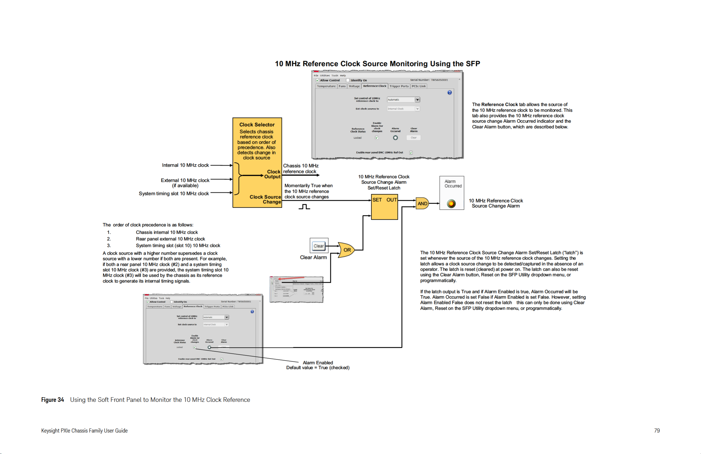
Page 80

Page 81

Page 82

82 Keysight PXIe Chassis Family User Guide
Page 83

PXIe Chassis Family
User Guide
8 Configuring the PXI Trigger Bus
Trigger management provides a systematic way for multiple applications to
share the eight PXIe backplane trigger lines without interfering with each other.
See the CAUTION below.
A generic trigger utility, KtMtrig (see page 101), is installed as part of the PXI
Chassis Family Driver for programmatic control of trigger management. It is a
“wrapper” around the PXI-9 Trigger Manager DLL specified in the PXI-9 Trigger
Management Specification. This is managed by the PXI Systems Alliance.
PXI-9-compliant trigger managers provide a way for applications, including
Keysight Connection Expert (part of the IO Libraries Suite), to dynamically query
to see if a trigger line is reserved, and if not, reserve it for use by that application.
In this way, multiple applications can coordinate their use of the shared chassis
trigger resources. It is the application programmer's responsibility to ensure that
all applications requiring trigger resources secure reservations and routes for
each client, and while in use, configure the instrument module drivers properly
so that only a single trigger source is driving any configured trigger line.
Many chassis backplane trigger lines don’t span the entire backplane, but
instead are split into two or three Trigger Bus Segments. Chassis with a
segmented trigger bus support the ability to route a trigger line from one
segment to another. This may be necessary if an application operates modules in
slots residing in multiple trigger bus segments. Trigger management provides a
way for applications to manage both trigger reservations and routes between
trigger bus segments.
- Ensure all your applications acquire trigger reservations prior
to asserting trigger events on a trigger line.
- Trigger signals can be generated by multiple modules, but
when multiple signals are placed on a trigger line
simul taneously, it can resul t in hard ware damage. The user is
responsible to ensure that multiple modules do not assert
triggers onto the same trigger line.
- When a trigger route is created in the chassis, the chassis
hardware drives the trigger line in the destination segment of
the route. Hardware damage can occur if modules in that
destination segment attempt to drive that same trigger line.
- The PXI-9-compatible chassis trigger manager makes it
possible to recover trigger reservations from other clients.
Improper use of this feature may take trigger lines away from
client applications that are depending on them.
83
Page 84

Configuring the PXI Trigger Bus Chassis Trigger Lines
Clients must also free their trigger resources when complete to
make them available again for use by other applications.
Chassis Trigger Lines
A PXI chassis backplane includes repeaters to route a trigger line across a bus
segment boundary. When the repeater is activated, via configuration, it relays
trigger signals asserted in the source trigger bus segment to the destination
trigger bus segment. The repeaters relay trigger signals between bus segments
in either direction, but not both directions at the same time (on a single trigger
line) – so one repeater allows a signal to be routed from bus segment 1 to bus
segment 2, and another repeater is used to route the other direction from bus
segment 2 to bus segment 1.
Viewing chassis trigger routes and reservations graphically can be done using
the Keysight IO Libraries Suit Connection Expert which provides the Chassis
Triggers View.
Figure 37 Keysight IO Libraries Connection Expert Chassis Triggers View (M9018B and M9019A)
84 Keysight PXIe Chassis Family User Guide
Page 85

Chassis Trigger Lines Configuring the PXI Trigger Bus
Trigger Bus Segments
The PXI chassis trigger bus consists of eight trigger lines spanning the chassis
backplane connectors.
– For the M9010A, the trigger lines are divided into two trigger bus
segments, labeled Segment 1 and Segment 2. Segment 1 covers chassis
slots 1 through 5 and Segment 2 covers slots 6 through 10.
– For the M9018B and M9019A, the trigger lines are divided into three
trigger bus segments, numbered 1 through 3. Segment 1 covers chassis
slots 1 through 6, Segment 2 covers slots 7 through 12, and Segment 3
covers slots 13 through 18.
By default, when you power-on the chassis, these trigger bus segments are
isolated from one another. Only the modules inside a given segment are able to
detect a trigger signal originating from another module in that same segment.
Attempting to drive a trigger bus line from two different trigger
bus segments may damage the trigger bridges between the
segments.
Trigger Line Reservations and Routing
Trigger Reservations: PXI chassis have trigger lines that are available to all of the
cards in a chassis. Sometimes, applications may need to reserve one or more of
the trigger lines, permanently or for a fixed time, for use by that application only.
This is a trigger reservation. Applications must heed the trigger reservations made
by other clients and avoid operating them.
Trigger Routes: Trigger lines in bus segments are independent unless the trigger
lines are explicitly connected between segments. This connection is a trigger
route. For each trigger line in a segment, you can enable buffers that to allow a
trigger signal on that line to flow out of one segment and into an adjacent
segment. A Trigger Route always has a source segment and a destination
segment.
Three trigger bus segments provide eight possible VALID trigger bus routes that
can be configured on any one trigger line. The following graphic shows all eight
trigger lines; each line is showing a different route so that all eight may be seen.
Any of these combinations can be applied to each of the eight trigger lines
PXI_TRIG[0:7].
Keysight PXIe Chassis Family User Guide 85
Page 86

Configuring the PXI Trigger Bus Chassis Trigger Lines
Figure 38 Example Showing the Eight Different Triggering Bus Routes
An example of an invalid Trigger Bus Route would be if the same trigger line in
both Segment 1 and Segment 3 tried to drive that Trigger Line line in Segment 2.
In the PXIe Family Chassis driver Soft Front Panel, trigger
reservations and trigger routes are not configurable. To configure
the Trigger Bus, use either the KtMTrig Trigger IVI driver or the IO
Libraries Suite Connection Expert. Connection Expert makes
Persistent Trigger Reservations with the Client ID of
Keysight_Persistent for a Graphical User Interface control
In past driver releases, chassis trigger routes were configurable
with the old, AgM9018 chassis driver for the M9018A. It
automatically made volatile Trigger Reservations with the Client
ID of AgM9018IviDriver_DefaultClient.
We strongly recommend that you make Trigger Bus Reservations
before you actually use the Trigger Lines in your application
programs.
.
86 Keysight PXIe Chassis Family User Guide
Page 87

Chassis Trigger Lines Configuring the PXI Trigger Bus
Some multi-slot PXI instruments, such as the Keysight M9381A PXIe Vector
Signal Generator, use peer-to-peer (module-to-module) triggering to function. If
you install these modules on the same trigger bus segment, no routes are
needed. But if you install them on different trigger bus segments, you must
configure trigger routes.
Persistent Versus Volatile Reservations
Volatile (dynamic) reservations will not persist through restarting (rebooting) the
host controller or the chassis. The PXIe Family Chassis Driver KtMTrig utility
creates volatile reservations and routes.
Persistent reservations, except in certain cases of conflicting reservations;
Persistent (or Static) reservations persist through restarting the host controller or
the chassis. Keysight IO Libraries Suite Connection Expert creates persistent
reservations and routes.
You can interactively create or remove persistent trigger reservations and routes
in Connection Expert's Chassis Triggers view. No changes are actually made to
the system until you click ACCEPT.
When you click ACCEPT, your changes are communicated to the underlying
Trigger Manager and thus to the chassis. At the same time, your changes are
also saved as persistent reservations. This means that they will be automatically
restored following a system restart (PC reboot or chassis power cycle).
Example: Persistent Versus Volatile Reservations
Suppose your system includes the reservations and routes shown below. The
Keysight Persistent reservations were made in the IO Libraries Suite Connection
Expert, and therefore they are Persistent reservations. The
AgM9018IviDriver_DefaultClient reservations were made programmatically and
are therefore volatile.
Figure 39 Trigger Routing with Persistent and Volatile Routing
Keysight PXIe Chassis Family User Guide 87
Page 88

Configuring the PXI Trigger Bus Chassis Trigger Lines
Close Connection Expert and reboot your PC. Then you restart Connection
Expert, and check the Trigger Routing, you see the following:
Figure 40 Trigger Routing after Reboot
The persistent reservations are still present (have persisted) after the reboot. The
volatile reservations are gone, and those trigger lines are available for new
reservations.
Configuring PXI Trigger Bus Connections
Volatile routes and reservations are made programmatically using the PXIe
Family Chassis Driver KtMTrig IVI driver. For information on using the KtMTrig IVI
driver, see the KtMTrig Help file:
Windows Start button > All Programs > Keysight > KtMTrig Help
Persistent routes and reservations can only be made through the Keysight
Connection Expert Chassis Triggers view. For detailed information on using
Connection Expert and the Chassis Triggers view, see the Keysight IO Libraries
help file.
88 Keysight PXIe Chassis Family User Guide
Page 89

Chassis Trigger Lines Configuring the PXI Trigger Bus
Front Panel Trigger Ports
In addition to the eight PXI trigger bus lines, the M9010A, M9018B and M9019A
chassis have two front panel 50 Ω SMB trigger connectors that you can assign to
any of the eight trigger lines of the PXI_TRIG [0:7] trigger bus.
These SMB trigger ports should be managed similarly to how PXI modules assert
or receive triggers on the trigger bus (see “Trigger Bus Segments” on page 85).
Figure 41 Chassis Front Panel Trigger Ports (M9019A chassis shown)
Make certain that your test application is not running when you
reconfigure these two trigger ports. Reconfiguring the ports from
input ports to output ports may cause unexpected noise on the
trigger port lines at the moment you make the change.
The M9010A 10-slot chassis backplane has two Trigger Bus Segments which are
numbered 1 and 2.
The M9018B and M9019A 18-slot chassis backplanes have three Trigger Bus
Segments which are numbered 1, 2, and 3.
Each front panel Trigger Port can be configured as Input or Output.
Trigger Port capability as a function of the firmware version
The front panel trigger port capability depends on the version of Trigger Bridge
firmware installed in your chassis. The Trigger Bridge firmware version 0, from
the 2017 firmware package, has less capability than the later version found in the
2018 firmware package. See “Updating Chassis Firmware” for instructions on
looking up your firmware version and updating the firmware.
Keysight PXIe Chassis Family User Guide 89
Page 90

Configuring the PXI Trigger Bus Chassis Trigger Lines
You can also determine which version you have by looking at your SFP Trigger
Ports tab. If the tab looks like the tab shown in the following example for the
M9019A, you have version 0.
Figure 42 M9019A SFP Trigger Ports when using Trigger Bridge firmware version 0.
Notice that with version 0, when the front panel trigger port is set to Input, the
front panel trigger port can only connect to a single PXI_TRIG line on trigger bus
segment 2. Also, with version 0, when the front panel trigger port is set to
Output, the front panel trigger port can only source the trigger signal from a
single PXI_TRIG line on trigger bus segment 2.
For the M9010A, the front panel trigger ports connect to trigger bus segment 1.
90 Keysight PXIe Chassis Family User Guide
Page 91

Chassis Trigger Lines Configuring the PXI Trigger Bus
If your SFP Trigger tab looks like the example shown in the following figure, you
have a later firmware version that provides the increased capability.
Figure 43 M9019A SFP Trigger Ports when using Trigger Bridge firmware after version 0.
Notice that with the later version, when the front panel trigger port is set to
Input, the front panel trigger port can connect to any and all PXI_TRIG lines on
either trigger bus segments 2 or 3 (or both). Also, with the later version, when
the front panel trigger port is set to Output, the front panel trigger port can
source the trigger signal from a single PXI_TRIG line on either trigger bus
segment 2 or 3.
The above description applies to both the M9018B and the M9019A, but with the
M9010A trigger bus segments 1 and 2 are used, instead of trigger bus segments
2 and 3.
Keysight PXIe Chassis Family User Guide 91
Page 92

Configuring the PXI Trigger Bus Chassis Trigger Lines
Trigger Port capability using Trigger Bridge 2018 firmware
The remainder of this chapter describes the front panel trigger port capability
when using the Trigger Bridge firmware from the 2018 firmware package. If you
need this capability and your chassis does not have the right firmware you can
update the firmware by downloading the 2018 firmware package from Keysight.
Please see “Updating Chassis Firmware” for instructions.
The M9010A 10-slot chassis backplane has two Trigger Bus Segments, which are
numbered 1 and 2. The M9010A front panel Trigger Ports can be configured to
connect to both segments using the SFP Trigger Ports screen or by using an IVI
software application.
The M9018B and M9019A 18-slot chassis backplanes have three Trigger Bus
Segments, which are numbered 1, 2, and 3. The front panel Trigger Ports can be
configured to connect to segments 2 and 3 using the SFP Trigger Ports screen or
by using an IVI software application.
Each front panel Trigger Port can be configured as an Input or an Output. When
configured as an Input, the incoming signal can be copied to multiple
PXI_TRIG[0:7] lines on both Trigger Bus Segments. When a front panel trigger
port is configured as an Output, the outgoing signal can sourced from only a
single PXI_TRIG[0:7] line from a single Trigger Bus Segment.
92 Keysight PXIe Chassis Family User Guide
Page 93

Chassis Trigger Lines Configuring the PXI Trigger Bus
Figure 44 M9010A SFP example configuration of the front panel Trigger Ports.
The preceding figure shows Trig Port 1 as an Output from PXI_TRIG4 on Trigger
Bus Segment 1 and Trig Port 2 as an Input to multiple PXI_TRIG lines on both
Segment 1 and 2.
Keysight PXIe Chassis Family User Guide 93
Page 94

Configuring the PXI Trigger Bus Chassis Trigger Lines
Figure 45 M9019A SFP example configuration of the front panel Trigger Ports.
The preceding figure shows Trig Port 1 as an Output from PXI_TRIG0 on Trigger
Bus Segment 2 and Trig Port 2 as an Input to multiple PXI_TRIG lines on both
Segment 2 and 3.
There can be only one source for a Trigger Signal.
When configuring either Trig 1 or Trig 2 as an Input Port:
- Do not configure PXI or PXIe modules in the same Trigger Bus
segment to generate trigger signals on the same trigger line.
- Do not route trigger signals from
the segment connected to Trig 1 and Trig 2 on the same
to
another Trigger Bus segment
trigger line.
94 Keysight PXIe Chassis Family User Guide
Page 95

Chassis Trigger Lines Configuring the PXI Trigger Bus
PXI TRIG0
Trigger Bus
Segment 1
Trigger Bus
Segment 2
Trigger Bus
Segment 3
PXI TRIG1
PXI TRIG2
PXI TRIG3
PXI TRIG4
PXI TRIG5
PXI TRIG6
PXI TRIG7
Trig 1
(Chassis Front Panel)
Trig 2
(Chassis Front Panel)
8 to 1
MUX
8 to 1
MUX
Input &
Push Pull
Output
Input &
Push Pull
Output
Figure 46 Wiring diagram illustration of an example front panel Trigger Port configuration.
The preceding figure illustrates a possible front panel Trigger Port configuration
using a wiring diagram. In this configuration, both Trigger Ports are connected to
Trigger Bus Segment 2.
The ports are always enabled; changing the drive type takes effect immediately.
Because it is possible that a configuration change can cause a signal to be
placed on a trigger line, it is recommended that you deactivate your test system
when making front panel Trigger Port configuration changes.
When the Trigger Port is set to Input, the default configuration is “none” for the
connection to PXI_TRIG[0:7] trigger signal lines.
When the front panel Trigger Port is set to Output, it is of type Push-Pull Output.
For the M9018B and M9019A, if you want to connect the front panel trigger
ports to Trigger Bus Segment 1, you must use Connection Expert to configure
trigger routes between Trigger Bus Segment 1 and Trigger Bus Segment 2.
Keysight PXIe Chassis Family User Guide 95
Page 96

Configuring the PXI Trigger Bus Front Panel Trigger Port Configuration Guidelines
Front Panel Trigger Port Configuration Guidelines
1 You may not configure more than one source for a trigger signal on a single
trigger line.
2 If you want the Trigger Port input signal to go to both segments, check
both boxes.
Note: The SFP Trigger Ports GUI and the IVI API do not enforce these guidelines.
However, if you ignore the guidelines, your trigger signal application might not
work.
1) You may not configure more than one source for a trigger
signal on a single trigger line.
Configuring more than one source for a trigger signal on a single trigger line can
damage trigger circuits and also block the generation of a trigger signal. When
you configure Trig 1 or Trig 2 as an input port, be careful to avoid configuring
modules or routes to use the same trigger lines on the same Trigger Bus
Segment.
If you configure Trig 1 or Trig 2 as an input port, follow these guidelines:
- Do not configure modules in that Trigger Bus Segment to drive trigger signals
on the same trigger line.
- Do not route trigger signals to that Trigger Bus Segment from an adjacent
Bus Segment on the same trigger line.
2) If you want the Trigger Port input signal to go to both
segments, check both boxes.
For Trigger Bridge firmware after version 0, be aware that if you want the input
Trigger Signal to go to both Bus Segments, you must check both boxes; you
cannot route the signal between segments. This guideline applies to Front Panel
Trigger Ports configured as Input and is not applicable to Trigger Ports that are
configured as Output. This guideline is not enforced by the SFP or by the IVI API.
See examples on the following pages.
96 Keysight PXIe Chassis Family User Guide
Page 97

Front Panel Trigger Port Configuration Guidelines Configuring the PXI Trigger Bus
The following figure is a section of the SFP Trigger Ports tab, showing both boxes
checked so that the front panel Trig 1 signal arrives on PXI_TRI0 on both Trigger
Bus Segments 2 and 3.
Figure 47 M9019A SFP example configuration of Trig 1 to PXI_TRIG0 on Segment 2 and 3.
You cannot use a route to propagate the Input Trigger signal between Bus
Segments 2 and 3. If you configure a route, the Front Panel Trigger Input trigger
signal is silently disabled.
Keysight PXIe Chassis Family User Guide 97
Page 98

Configuring the PXI Trigger Bus Front Panel Trigger Port Configuration Guidelines
When Trig 1 is configured as Input, you can select the set of PXI_TRIG[0:7] lines
that receive the incoming signal. This set can include all the PXI_TRIG[0] through
PXI_TRIG[7] on both Segments 2 and 3. The following figure shows a portion of
the SFP Trigger Ports tab, where the configuration of front panel Trig 1 goes to
all possible locations:
Figure 48 M9019A SFP example Trig 1 connected to all PXI_TRIG lines on Segments 2 and 3.
98 Keysight PXIe Chassis Family User Guide
Page 99

Front Panel Trigger Port Configuration Guidelines Configuring the PXI Trigger Bus
The following figure shows a simpler configuration, in which only PXI-TRIG0 on
Trigger Bus Segment 3 receives the incoming Trigger Port signal:
Figure 49 M9019A SFP example with Trig 1 only connected to PXI_TRIG0 on Segment 3..
This configuration is silently ignored in situations where you also configure a
route on the same trigger line from Trigger Bus Segment 3 to Trigger Bus
Segment 2, as shown in the following example of the Connection Expert Chassis
Trigger tab:
Figure 50 Connection Expert example showing a route on PXI_TRIG0 from Segment 3 to Segment 2.
If you have a route from Trigger Bus Segment 3, you cannot configure a Front
Panel Trigger Port signal on that trigger line on Bus Segment 3. If you attempt
such a configuration, the check box specification shown above is silently ignored
and the input trigger signal is not copied to PXI TRIG0 Bus Segment 3.
Keysight PXIe Chassis Family User Guide 99
Page 100

Configuring the PXI Trigger Bus Front Panel Trigger Port Configuration Guidelines
This configuration limitation applies to both directions between Bus 2 and Bus 3.
If you want an input trigger signal to go to both segments, you must check both
boxes. You cannot route the signal between Segment 2 and Segment 3.
This configuration limitation applies to both the GUI and programing interface
using IVI.
The M9018B and the M9019A chassis have three Trigger Bus Segments, which
are numbered 1, 2, and 3. However, the M9010A 10-slot chassis has two Trigger
Bus Segments, which are numbered 1 and 2. With the M9010A, if you want an
input trigger signal to go to both Segments 1 and 2, then you must check both
boxes. You cannot route them between Segments 1 and 2.
100 Keysight PXIe Chassis Family User Guide
 Loading...