

Page 1

User’s Guide
Keysight M8197A
Synchronization module for M8195A
Page 2

Notices
CAUTION
WARNING
Copyright Notice
© Keysight Technologies 2017
No part of this manual may be reproduced in any form or by any means
(including electronic storage and retrieval
or translation into a foreign language)
without prior agreement and written consent from Keysight Technologies, Inc. as
governed by United States and international copyright laws.
Manual Part Number
M8197-91020
Edition
Edition 4.0, October 2017
Published by:
Keysight Technologies
Deutschland GmbH,
Herrenberger Str. 130,
71034 Böblingen, Germany
Technology Licenses
The hardware and/or software described
in this document are furnished under a
license and may be used or copied only
in accordance with the terms of such
license.
ESD Sensitive Device
All front-panel connectors of the
M8195A are sensitive to Electrostatic
discharge (ESD). We recommend to
operate the instrument in an
electrostatic safe environment.
There is a risk of instrument malfunction
when touching a connector.
Please follow this instruction:
Before touching the front-panel
connectors, discharge yourself by
touching the properly grounded
mainframe.
U.S. Government
Rights
The Software is “commercial computer
software,” as defined by Federal Acquisition Regulation (“FAR”) 2.101. Pursuant
to FAR 12.212 and 27.405-3 and Department of Defense FAR Supplement
(“DFARS”) 227.7202, the U.S. government acquires commercial computer
software under the same terms by which
the software is customarily provided to
the public. Accordingly, Keysight provides the Software to U.S. government
customers under its standard commercial
license, which is embodied in its End
User License Agreement (EULA), a copy
of which can be found at http://
www.keysight.com/find/sweula. The li-
cense set forth in the EULA represents
the exclusive authority by which the U.S.
government may use, modify, distribute,
or disclose the Software. The EULA and
the license set forth therein, does not
require or permit, among other things,
that Keysight: (1) Furnish technical information related to commercial computer
software or commercial computer software documentation that is not customarily provided to the public; or (2) Relinquish to, or otherwise provide, the government rights in excess of these rights
customarily provided to the public to use,
modify, reproduce, release, perform, display, or disclose commercial computer
software or commercial computer software documentation. No additional government requirements beyond those set
forth in the EULA shall apply, except to
the extent that those terms, rights, or
licenses are explicitly required from all
providers of commercial computer software pursuant to the FAR and the DFARS
and are set forth specifically in writing
elsewhere in the EULA. Keysight shall be
under no obligation to update, revise or
otherwise modify the Software. With
respect to any technical data as defined
by FAR 2.101, pursuant to FAR 12.211
and 27.404.2 and DFARS 227.7102, the
U.S. government acquires no greater
than Limited Rights as defined in FAR
27.401 or DFAR 227.7103-5 (c), as applicable in any technical data.
Warranty
THE MATERIAL CONTAINED IN THIS
DOCUMENT IS PROVIDED “AS IS,”
AND IS SUBJECT TO BEING
CHANGED, WITHOUT NOTICE, IN
FUTURE EDITIONS. FURTHER, TO
THE MAXIMUM EXTENT PERMITTED
BY APPLICABLE LAW, KEYSIGHT
DISCLAIMS ALL WARRANTIES, EITHER EXPRESS OR IMPLIED, WITH
REGARD TO THIS MANUAL AND
ANY INFORMATION CONTAINED
HEREIN, INCLUDING BUT NOT LIMITED TO THE IMPLIED WARRANTIES
OF MERCHANTABILITY AND FITNESS FOR A PARTICULAR PURPOSE. KEYSIGHT SHALL NOT BE
LIABLE FOR ERRORS OR FOR INCIDENTAL OR CONSEQUENTIAL DAMAGES IN CONNECTION WITH THE
FURNISHING, USE, OR PERFORMANCE OF THIS DOCUMENT OR OF
ANY INFORMATION CONTAINED
HEREIN. SHOULD KEYSIGHT AND
THE USER HAVE A SEPARATE
WRITTEN AGREEMENT WITH WARRANTY TERMS COVERING THE MATERIAL IN THIS DOCUMENT THAT
CONFLICT WITH THESE TERMS,
THE WARRANTY TERMS IN THE
SEPARATE AGREEMENT SHALL
CONTROL.
Safety Information
A CAUTION notice denotes a hazard.
It calls attention to an operating
procedure, practice, or the like that,
if not correctly performed or adhered
to, could result in damage to the
product or loss of important data. Do
not proceed beyond a CAUTION
notice until the indicated conditions
are fully understood and met.
A WARNING notice denotes a hazard. It calls attention to an operating
procedure, practice, or the like that,
if not correctly performed or adhered
to, could result in personal injury or
death. Do not proceed beyond a
WARNING notice until the indicated
conditions are fully understood and
met.
Page 3

General Safety
Precautions
The following general safety precautions must be observed during all phases of
operation of this instrument. Failure to comply with these precautions or with
specific warnings elsewhere in this manual violates safety standards of design,
manufacture, and intended use of the instrument. For safe operation the general
safety precautions for the M9502A and M9505A AXIe chassis, must be followed.
See: http://www.keysight.com/find/M9505A Keysight Technologies Inc. assumes
no liability for the customer's failure to comply with these requirements. Before
operation, review the instrument and manual for safety markings and instructions.
You must follow these to ensure safe operation and to maintain the instrument in
safe condition.
Initial Inspection
Inspect the shipping container for damage. If there is damage to the container or
cushioning, keep them until you have checked the contents of the shipment for
completeness and verified the instrument both mechanically and electrically. The
Performance Tests give procedures for checking the operation of the instrument. If
the contents are incomplete, mechanical damage or defect is apparent, or if an
instrument does not pass the operator’s checks, notify the nearest Keysight
Technologies Sales/Service Office.
WARNING To avoid hazardous electrical shock, do not perform electrical tests
when there are signs of shipping damage to any portion of the outer enclosure
(covers, panels, etc.).
General
This product is a Safety Class 3 instrument. The protective features of this product
may be impaired if it is used in a manner not specified in the operation
instructions.
Environment
Conditions
This instrument is intended for indoor use in an installation category II, pollution
degree 2 environment. It is designed to operate within a temperature range of 0
°C – 40 °C (32 °F – 105 °F) at a maximum relative humidity of 80% and at altitudes
of up to 2000 meters.
This module can be stored or shipped at temperatures between -40 °C and +70 °C.
Protect the module from temperature extremes that may cause condensation
within it.
Before Applying Power
Verify that all safety precautions are taken including those defined for the
mainframe.
Line Power
Requirements
The Keysight M8197A operates when installed in an Keysight AXIe mainframe.
Do Not Operate in an
Explosive Atmosphere
Do not operate the instrument in the presence of flammable gases or fumes.
Do Not Remove the
Instrument Cover
Operating personnel must not remove instrument covers. Component replacement
and internal adjustments must be made only by qualified personnel. Instruments
that appear damaged or defective should be made inoperative and secured
against unintended operation until they can be repaired by qualified service
personnel.
Safety Summary
Page 4

Symbol
Description
Indicates warning or caution. If you see this symbol on a product, you must refer to the manuals for
specific Warning or Caution information to avoid personal injury or damage to the product.
C-Tick Conformity Mark of the Australian ACA for EMC compliance.
CE Marking to state compliance within the European Community: This product is in conformity with the
relevant European Directives.
General Recycling Mark
Symbol
Description
This product complies with the WEEE Directive (2002/96/EC) marketing requirements. The affixed label
indicates that you must not discard this electrical/electronic product in domestic household waste.
Product category: With reference to the equipment types in the WEEE Directive Annexure I, this product
is classed as a “Monitoring and Control instrumentation” product.
Do not dispose in domestic household waste.
To return unwanted products, contact your local Keysight office, or see
http://about.keysight.com/en/companyinfo/environment/takeback.shtml for more information.
Safety Symbols
Table 1 Safety Symbol
Table 2 Compliance and Environmental Information
Page 5

Contents
1 Introduction
2 M8197A Installation
Contents
1.1 Document History 11
1.2 Accessories 11
1.3 M8197A Front Panel 11
1.3.1 Front Panel LED 12
2.1 Introduction 16
2.1.1 Pre-Requisites 16
2.1.2 Installation Process 17
2.1.3 Post Installation Steps 25
2.1.4 How to Control the Instrument 26
2.2 AXI Chasis 26
2.2.1 ESM Front Panel Connector 26
3 System Configuration
4 M8197A Soft Front Panel
3.1 Introduction 30
3.1.1 Up to 4 M8195A AWG Channels in an M9502A 2-Slot
Chassis 31
3.1.2 Up to 16 M8195A AWG Channels in an M9505A 5-Slot
Chassis 31
3.1.3 Up to 16 M8195A AWG Channels in an M9514A 14-Slot
Chassis 31
3.2 Supported AXIe Frame Combinations 32
3.3 Controlling One AXIe Chassis 33
3.4 Synchronous System Cabling 35
3.5 Controlling the Synchronous System 36
3.5.1 Requirements for Controlling the Synchronous System 36
3.5.2 Synchronous System Operation Modes 36
3.5.3 Control Parameters 38
4.1 Introduction 42
4.2 Launching the M8197A Soft Front Panel 42
4.3 M8197A Soft Front Panel 43
4.3.1 Title Bar 44
4.3.2 Menu Bar 44
4.3.3 Status Bar 46
4.3.4 Tabs (Module/Clock/Trigger/Dynamic Control Tabs) 46
4.3.5 Numeric Control Usage 46
Keysight M8197A User’s Guide 5
Page 6

Contents
4.4 Driver Call Log Window 48
4.5 Errors List Window 49
4.6 Module Tab50
4.7 Clock Tab 52
4.8 Trigger Tab 53
4.9 Dynamic Control Tab 55
5 Remote Programming
5.1 Introduction 58
5.2 SCPI Programming 58
5.2.1 AgM8197SFP.exe 59
5.3 Programming Recommendations 61
5.4 System Related Commands (SYSTem Subsystem) 62
5.4.1 :SYSTem:ERRor[:NEXT]? 62
5.4.2 :SYSTem:HELP:HEADers? 62
5.4.3 :SYSTem:LICense:EXTended:LIST? 63
5.4.4 :SYSTem:SET[?] 63
5.4.5 :SYSTem:VERSion? 63
5.4.6 :SYSTem:COMMunicate:*? 64
5.4.7 :SYSTem:DYNPort:* 66
5.5 Common Command List 67
5.5.1 *IDN? 67
5.5.2 *CLS 67
5.5.3 *ESE 67
5.5.4 *ESR? 67
5.5.5 *OPC 67
5.5.6 *OPC? 67
5.5.7 *OPT? 68
5.5.8 *RST 68
5.5.9 *SRE[?] 68
5.5.10 *STB? 68
5.5.11 *TST? 68
5.5.12 *LRN? 68
5.5.13 *WAI 68
5.6 Status Model 69
5.6.1 :STATus:PRESet 71
5.6.2 Status Byte Register 71
5.6.3 Questionable Data Register Command Subsystem 72
5.6.4 Operation Status Subsystem 74
5.6.5 Run Status Subsystem 75
5.7 ARM/TRIGger Subsystem 76
5.7.1 :ABORt 76
5.7.2 :INITiate:CONTinuous:ENABle[?] SELF|ARMed 76
5.7.3 :INITiate:CONTinous[:STATe][?] OFF|ON|0|1 76
6 Keysight M8197A User’s Guide
Page 7

Contents
5.7.4 :INITiate:GATE[:STATe][?] OFF|ON|0|1 77
5.7.5 :INITiate:IMMediate 77
5.7.6 :ARM[:SEQuence][:STARt][:LAYer]:TRIGger:LEVel[?]
<level>|MINimum|MAXimum 78
5.7.7 :ARM[:SEQuence][:STARt][:LAYer]:TRIGger:SLOPe[?]
POSitive|NEGative|EITHer 78
5.7.8 :ARM[:SEQuence][:STARt][:LAYer]:TRIGger:SOURce[?]
TRIGger|EVENt|INTernal 79
5.7.9 :ARM[:SEQuence][:STARt][:LAYer]:TRIGger:FREQuency[?]
<frequency>|MINimum|MAXimum 79
5.7.10 :ARM [:SEQuence][:STARt][:LAYer]:TRIGger:OPERation[?]
ASYNchronous|SYNChronous 80
5.7.11 :ARM[:SEQuence][:STARt][:LAYer]:EVENt:LEVel[?]
<level>|MINimum|MAXimum 80
5.7.12 :ARM[:SEQuence][:STARt][:LAYer]:EVENt:SLOPe[?]
POSitive|NEGative|EITHer 80
5.7.13 :ARM[:SEQuence][:STARt][:LAYer]:DYNPort:WIDTh[?]
LOWerbits|ALLBits 81
5.7.14 :TRIGger[:SEQuence][:STARt]:SOURce:ENABle[?]
TRIGger|EVENt 81
5.7.15 :TRIGger[:SEQuence][:STARt]:ENABle:HWDisable[:STATe][?]
0|1|OFF|ON 82
5.7.16 :TRIGger[:SEQuence][:STARt]:BEGin:HWDisable[:STATe][?]
0|1|OFF|ON 82
5.7.17 :TRIGger[:SEQuence][:STARt]:ADVance:HWDisable[:STATe][?]
0|1|OFF|ON 83
5.8 TRIGger – Event/Trigger Input 84
5.8.1 :TRIGger[:SEQuence][:STARt]:SOURce:ADVance[?]
TRIGger|EVENt|INTernal 84
5.8.2 :TRIGger[:SEQuence][:STARt]:ENABle[:IMMediate] 84
5.8.3 :TRIGger[:SEQuence][:STARt]:BEGin[:IMMediate] 84
5.8.4 TRIGger[:SEQuence][:STARt]:BEGin:GATE[:STATe][?]
OFF|ON|0|1 85
5.8.5 :TRIGger[:SEQuence][:STARt]:ADVance[:IMMediate] 85
5.9 INSTrument Subsystem 86
5.9.1 :INSTrument:SLOT[:NUMBer]? 86
5.9.2 Multi-module configuration commands 86
5.10 MMEMory Subsystem 88
5.10.1 :MMEMory:CATalog? [<directory_name>] 89
5.10.2 MMEMory:CDIRectory [<directory_name>] 90
5.10.3 :MMEMory:COPY <string>,<string>[,<string>,<string>] 90
5.10.4 :MMEMory:DELete <file_name>[,<directory_name>] 91
5.10.5 :MMEMory:DATA <file_name>, <data> 91
5.10.6 :MMEMory:DATA? <file_name> 91
5.10.7 :MMEMory:MDIRectory <directory_name> 92
5.10.8 :MMEMory:MOVE <string>,<string>[,<string>,<string>] 92
5.10.9 :MMEMory:RDIRectory <directory_name> 92
5.10.10 :MMEMory:LOAD:CSTate <file_name> 93
5.10.11 :MMEMory:STORe:CSTate <file_name> 93
Keysight M8197A User’s Guide 7
Page 8

Contents
5.11 OUTPut Subsystem 94
5.11.1 :OUTPut: ROSCillator:SOURce[?]
INTernal|EXTernal|SCLK1|SCLK2 94
5.11.2 :OUTPut: ROSCillator:SCD[?] <sample_clock_divider> 94
5.11.3 :OUTPut: ROSCillator:RCD1[?] < reference_clock_divider1> 95
5.11.4 :OUTPut: ROSCillator:RCD2[?] <reference_clock_divider2> 95
5.12 Sampling Frequency Commands 95
5.12.1 [:SOURce]:FREQuency:RASTer[?]
<frequency>|MINimum|MAXimum 95
5.13 Reference Oscillator Commands 96
5.13.1 [:SOURce]:ROSCillator:SOURce[?] EXTernal|AXI|INTernal 96
5.13.2 [:SOURce]:ROSCillator:SOURce:CHECk?
EXTernal|AXI|INTernal 96
5.13.3 [:SOURce]:ROSCillator:FREQuency[?]
<frequency>|MINimum|MAXimum 96
5.13.4 [:SOURce]:ROSCillator:RANGe[?] RANG1| RANG2 97
5.13.5 [:SOURce]:ROSCillator:RNG1|RNG2:FREQuency[?]
<frequency>|MINimum|MAXimum 97
5.14 STABle Subsystem 98
5.14.1 [:SOURce]:STABle:DYNamic:SELect
<sequence_table_index> 98
6 Characteristics
5.15 TEST Subsystem 98
5.15.1 :TEST:PON? 98
5.15.2 :TEST:TST? 98
6.1 Performance Specification 100
6.2 General 100
6.3 Maintenance 101
6.3.1 ESD Protection 101
6.3.2 Power and Ventilation Requirements 101
6.3.3 Thermal Protection 102
6.3.4 Cleaning Recommendation 102
8 Keysight M8197A User’s Guide
Page 9

Keysight M8197A - Synchronization module for M8195A
User’s Guide
1 Introduction
1.1 Document History / 11
1.2 Accessories / 11
1.3 M8197A Front Panel / 11
Page 10

1 Introduction
Introduction
This chapter provides an overview of Keysight M8197A module.
The M8197A synchronization module is used together with 1 to 4 M8195A modules to build a fully
synchronous, phase coherent multi-channel generator system with up to 16 analog channels.
When running in synchronous mode, all of the M8195A modules work with the same sample clock and
start at the same time. The common system clock (Sys Clk) is derived either from the M8197A’s
internal clock synthesizer or from an external sample clock that is connected to the M8197A’s
reference clock input (REF CLK IN).
The skew between any two channels is guaranteed to be within +/- 75 ps (without system level
calibration) independent of the sample rate. Using the fine delay adjust capability of the M8195A with
50 fs resolution, the skew can be adjust to less than 1 ps between any two channels. Once adjusted,
the skew is maintained across loading new waveforms, changing sample rate and power cycles to
better than 1 ps.
A common trigger input is available on the synchronization module to trigger all the connected
M8195A modules simultaneously with deterministic latency. Triggered waveforms have the same
inter-channel skew as continuous waveforms. To achieve the lowest possible trigger delay
uncertainty, the trigger input can be synchronized externally to the REF CLK output.
Features and Benefits
M8197A provides following features and benefits:
Synchronization of up to 4 M8195A modules (= 16 channels)
One trigger input can trigger up to 4 M8195A modules with deterministic
latency
Skew repeatability of 1 ps between any two channels – independent of
sample rate
Skew resolution of 50 fs between any two M8195A of the synchronous
system
1U AXIe module for high port density
Additional Documents
Additional documentation can be found at:
http://www.keysight.com/find/M9505A for 5-slot chassis related
documentation.
http://www.keysight.com/find/M9502A for 2-slot chassis related
documentation.
http://www.keysight.com/find/M9048A for PCIe desktop adapter card
related documentation.
http://www.keysight.com/find/M9536A for embedded AXIe controller
related documentation.
http://www.keysight.com/find/M8195A for AXIe based AWG module
related documentation.
10 Keysight M8197A User’s Guide
Page 11

1.1 Document History
First Edition
(November 2015)
The first edition of the user guide describes the functionality of firmware version 2.5.
Second Edition
(April 2016)
The second edition of the user guide describes the functionality of firmware version
3.0.
Third Edition
(July 2016)
The third edition of the user guide describes the functionality of firmware version 3.1.
Fourth Edition
(Oct
2017)
1.2 Accessories
Introduction 1
The
fourth edition of the user guide describes the functionality of firmware version 3.1.
1.3 M8197A Front Panel
Inputs/Outputs
The M8197A is always delivered with four Sys clock cables. The Sys Clock cables are
matched pair cables. It is mandatory to use exactly the provided cables. Otherwise
the synchronous system will not operate as specified. To avoid using non-specified
cables, the Sys Clock cables are equipped with QMA to SMA connectors.
The following figure shows the front panel of the M8197A module:
Figure 1 Front Panel of M8197A
The inputs and outputs available on the front panel of the M8197A module are
described in Table 3.
Keysight M8197A User’s Guide 11
Page 12

1 Introduction
Input/Outputs
Description
Connector Type
DYNAMIC CONTROL IN /
OUT
Configured as parallel Input port: Used to control sequencing of
the synchronous system by external signals. This input is defined
in detail in the chapter Sequencing of the User’s Guide of the
M8195
Configured as parallel Output port: General purpose parallel
digital I/O.
Proprietary parallel connector
SYS CLK OUT
Connect to Trig In of each M8195A that is part of the synchronous
system
QMA
TRIG IN
The Trigger Input has a combined functionality as Trigger or Gate
and is used to start the synchronous system by an external signal.
This input is defined in detail in the chapter Sequencing of the
User’s Guide of the M8195
SMA
EVENT IN
The Event Input (EVENT IN) is used to e.g. step through segments
or scenarios by an external signals. This input is defined in detail
in the chapter Sequencing of the User’s Guide of the M8195.
SMA
REF CLK IN
The Reference Clock Input can be used to synchronize to an
external clock. The input frequency can vary between 10MHz and
17 GHz.
SMA
REF CLK OUT
The Reference Clock Output can be used to synchronize a DUT to
the M8197A and thus to the synchronous system. The adjustable
output frequency covers a large frequency range.
SMA
Two LEDs are available at the front panel to indicate the status of the M8197A
module:
The green “Access” LED indicates that the controlling PC exchanges data with the
M8197A module.
The red “Fail” LED has following functionality:
It is “ON” for about 30 seconds after powering the AXIe chassis.
After about 30 seconds, the LED is switched “OFF”. If an external PC is used
to control the AXIe chassis, this PC can be powered after this LED has
switched OFF.
During normal operation of the module this LED is “OFF”. In case of an error
condition e.g. a self-test error, the LED is switch “ON”.
In case the output relay has shut-off because of an external overload
condition, this LED flashes.
Table 3 Inputs and Outputs available on the front panel of the M8197A module
1.3.1 Front Panel LED
1.3.1.1 Status LED
12 Keysight M8197A User’s Guide
Page 13

This LED indicates that an externally applied signal matches the adjusted threshold
to be used as a Trigger or Event. The LED turns on for ~100 ms for each detected
edge of the correct polarity i.e. a rising edge turns the LED on for 100 ms if the
polarity is adjusted to rising.
If the polarity is adjusted to rising, and a falling edge is externally applied, the LED
remains OFF.
Notes:
In case the edges are applied faster than every 100 ms, the LED is
continuously ON.
In trigger mode ‘Gated’, the LED is turned on for 100 ms when the gate
signal becomes active i.e. when the polarity is set to positive, the LED turns
on for 100 ms after the rising edge. When the polarity is set to negative, the
LED turns on for 100 ms after the falling edge.
In trigger mode ‘Gated’, the polarity cannot be set to ‘Either’
Color
Meaning
Description
Off
No external Trigger (Event)
In case the trigger source is not set to external, this LED is OFF.
ON, green
Valid external Trigger (Event)
detected
In case the trigger mode is set to ‘asynchronous’, a Trigger (Event) is
always valid. Set-up or hold time violations do not exists.
Note: A ‘Force Trigger’ from the SFP or SCPI does not turn the LED ON
ON, red
Invalid external Trigger
(Event) detected
In case the trigger mode is set to ‘synchronous’, a Trigger (Event) can
be invalid because of a set-up or hold time violation. The LED turns On
red in case a set-up or a hold time violation has been detected.
Note A ‘Force Trigger’ from the SFP or SCPI does not turn the LED ON
1.3.1.2 Trigger IN and Event IN LED
Table 4: Trigger IN and Event IN LED
Introduction 1
Keysight M8197A User’s Guide 13
Page 14

1 Introduction
Color
Meaning
Description
Off
Applied clock cannot be used
In case the clock reference is not set to Ref CLK IN, this LED is OFF.
ON, green
Valid signal at Ref CLK IN detected
CDR has locked on Ref CLK In and
The externally applied frequency is correct and
Ref CLK In has been selected as the clock reference
ON, red
No valid signal at Ref CLK IN
Ref CLK In has been selected as the clock reference
The externally applied clock signal is not valid. E.g. the
frequency does not match the adjusted value or the
amplitude is outside the specified range
1.3.1.3 Ref CLK IN LED
Table 5: Ref CLK IN LED
14 Keysight M8197A User’s Guide
Page 15

Keysight M8197A - Synchronization module for M8195A
User’s Guide
2 M8197A Installation
2.1 Introduction / 16
2.2 AXI Chasis / 26
Page 16

2 M8197A Installation
This chapter explains the steps required to install M8197A module.
The following are the pre-requisites for installing Keysight M8197A software:
The supported operating systems are:
Windows 10 (32 bit or 64 bit)
Windows 8.1 (32 bit or 64 bit)
Windows 8 (32 bit or 64 bit)
Windows 7 (32 bit or 64 bit)
Ensure that you have Keysight IO Libraries Suite Version 16.3 or higher
installed on your system. The Keysight IO Libraries Suite can be found on
the CD that is part of shipment content or at
http://www.Keysight.com/find/iosuite.
2.1 Introduction
2.1.1 Pre-Requisites
16 Keysight M8197A User’s Guide
Page 17

Follow the given steps to install Keysight M8197A software on your system:
1. Double-click the executable (M8197_Setup.exe). This executable file is
available either on CD or Web.
2. The Keysight M8197A Setup will prepare the InstallShield Wizard for the
installation process. The following windows will appear.
2.1.2 Installation Process
M8197A Installation 2
Keysight M8197A User’s Guide 17
Page 18

2 M8197A Installation
3. Click Next.
4. We recommend you to read the document to check if your hardware
configuration is supported.
Click Next to proceed to the license agreements.
18 Keysight M8197A User’s Guide
Page 19

M8197A Installation 2
5. Accept the terms of ‘Keysight Software End-User License Agreement’.
6. Click Next.
Keysight M8197A User’s Guide 19
Page 20

2 M8197A Installation
7. Accept the ‘Keysight IVI Driver Source Code License Agreement Terms’.
8. Click Next.
20 Keysight M8197A User’s Guide
Page 21

M8197A Installation 2
9. Select Yes if you want to read the post-installation instructions.
Click Next to select setup type.
10. Select a setup type either Complete or Custom.
If you select Custom, you can specify which optional features will be installed.
Keysight M8197A User’s Guide 21
Page 22

2 M8197A Installation
11. Click Next.
22 Keysight M8197A User’s Guide
Page 23

M8197A Installation 2
12. Click Install to begin the installation. The Setup Wizard will now install
M8197A.
Keysight M8197A User’s Guide 23
Page 24

2 M8197A Installation
13. The following screen will appear once the Keysight M8197A software is
successfully installed on your system.
14. Click Finish to restart your system.
This completes the Keysight M8197A software installation.
24 Keysight M8197A User’s Guide
Page 25

2.1.3 Post Installation Steps
If M8197A is already powered up and connected to PC using the PCIe, just reboot
the PC, and start with step 5. No such reboot step is required in case of a USB
connection.
Follow the post installation steps as shown below:
1. Shut down PC and instrument.
2. Connect the instrument to the PC using a PCIe or USB cable.
3. Switch on instrument. Wait until the “Access” LED of the M8197A has
switched from red to green.
4. Switch on PC.
5. The PC should automatically recognize the instrument.
6. Check this in the device manager; e.g. via Start > Control Panel > Device
Manager, or right-click Computer > Manage > Device Manager:
In case of PCIe:
7. The instrument should be visible in the device tree as Keysight Technologies
Modular Devices > M8197A
In case of USB:
8. The instrument should be visible in the device tree as Keysight Modular
Platform (AMP/AXIe) > Keysight Technologies USB AMP/AXIe Chassis.
In case of PCIe, post installation steps must be followed strictly in the same order as
mentioned for successful connection of the PC with M8197A. However, in case of
USB no such restriction is applicable i.e. the PC can be powered before the M8197 is
turned ON.
Your PC might request a reboot. Reboot your PC, if requested.
9. (PCIe only) Check if the M8197 is also visible in the Keysight Connection
Expert:
e.g. via Start > All Programs > Keysight Connection Expert.
10. If something went wrong and the Instrument is not shown in the PXI section,
it may be necessary to reboot the PC once more.
11. Install Intel Network Drivers on Windows XP: The AXIe chassis contains an
Intel 82573L NIC as a PCIe endpoint. Refer to the AXIe chassis User’s Guide
at http://www.Keysight.com/find/M9505A for instructions how to install this
driver.
M8197A Installation 2
Keysight M8197A User’s Guide 25
Page 26

2 M8197A Installation
1. If you use a PCIe link to control the M8197A, the AXIe chassis must be
switched-on before you start the PC. If you use a USB link to control the
M8197A, it’s not mandatory that the AXIe chassis is powered and has
booted prior to turning on the PC.
2. Start the M8197A Soft Front Panel (Start > All Programs > Keysight M8197
> Keysight M8197 Soft Front Panel). The user interface will display the VISA
resource strings for different kinds of connection.
3. Using the appropriate VISA resource string you can:
Start the Soft Front Panel (Start > All Programs > Keysight M8197 >
Keysight M8197 Soft Front Panel).
Control the instrument with your own application using the M8197
IVI Drivers or add it as a LAN instrument in the Keysight Connection
Expert (TCPIP0::localhost::…) and control it using SCPI (with e.g. the
VISA Assistant or your own application).
4. You must start the M8197A Soft Front Panel in order to send SCPI commands
to the instrument.
The M8197 IVI Drivers start the M8197A Soft Front Panel automatically.
The detailed documentation for the AXIe chassis can be found at:
http://www.Keysight.com/find/M9505A for 5-slot chassis
http://www.Keysight.com/find/M9502A for 2-slot chassis.
The ESM Front Panel Connector is shown in the figure below:
1 2 3
4
5
6
7
8 9
2.1.4 How to Control the Instrument
2.2 AXI Chasis
2.2.1 ESM Front Panel Connector
26 Keysight M8197A User’s Guide
Page 27

M8197A Installation 2
1
PCle
Connects a host PC to the chassis via PCle.
PCIe is the only interface that can be used to control the M8197A
module.
2
Multiframe Input
Synchronizes timing signals with multiple daisy-chained chassis. These
signals are not needed to synchronize M8190A modules. The M8197A
synchronization module is needed instead.
3
Multiframe Output
4
Trigger In
External Trigger connections.
The Trigger In of the AXIe ESM cannot be used to trigger the M8197A.
The M8197A has its own Trigger In.
The Trigger Out of the AXIe ESM cannot be controlled by the M8197A.
5
Trigger Out
6
Clock In
External clock connections.
7
Clock Out
8
LAN
Connects the host PC to the chassis, via 10/100/1000 Ethernet.
In particular, the LAN connector is used for ESM configuration, but NOT
to communicate to the M8197A.
9
Status Light
Indicates the chassis status.
Keysight M8197A User’s Guide 27
Page 28

Page 29

Keysight M8197A - Synchronization module for M8195A
User’s Guide
3 System Configuration
3.1 Introduction / 30
3.2 Supported AXIe Frame Combinations / 32
3.3 Controlling One AXIe Chassis / 33
3.4 Synchronous System Cabling / 35
3.5 Controlling the Synchronous System / 36
Page 30

3 System Configuration
This chapter describes how to configure a synchronous system. The term
‘synchronous system’ describes multiple M8195A AWG modules that operate entirely
synchronous with respect to timing parameters including synchronous start,
synchronous sequencing, common trigger and common sample clock. A
synchronous system consists of:
One M8197A synchronization module
One or up to four M8195A AWG slave modules
One M9502A 2-slot AXIe chassis or one M9505A 5-slot AXIe chassis
An external PC to control the synchronous system
One clock cable M8197-61601 for each synchronized M8195A AWG slave
module
M8197A software that controls the synchronous operation of the system
M8195A software that controls the operation of the M8195A AWG modules
There are some generic rules to be considered for the configuration of a synchronous
system. The M8197A synchronization module must always be inserted in the lowest
slot number of the synchronous system. The M8197A and M8195A modules of the
synchronous system must be inserted in ascending slot numbers without leaving a
slot empty. In case a M9536A system controller module is used, the controller
module must be inserted in slot 1.
The M8197A synchronization module is designed to synchronize up to four M8195A
arbitrary waveform generator modules. The M8195A modules have to be located in
the same AXIe chassis as the M8197A in direct order above the M8197A.
A synchronous trigger signal to start the system synchronously is distributed via the
AXIe chassis backplane and a system clock signal is distributed using the clock
cables M8197-61601. These clock cables are connected on the front panel between
the M8197A synchronization module and the M8195A arbitrary waveform generator
modules.
All synchronous system configurations require an external desktop PC or laptop PC
with PCIe interface cable connection or USB cable connection to control the system.
As alternative to an external PC, a M9536A system controller module can be used to
control the system.
Any number of up to 16 Arbitrary Waveform Generator channels can be configured
using a combination of 1-channel, 2-channel and 4-channel M8195A Arbitrary
Waveform Generators (see section 3.2). Typical multi-channel configurations are
described in the following subchapters:
3.1 Introduction
30 Keysight M8197A User’s Guide
Page 31

To configure a synchronous system with up to 4 AWG-channels including high
resolution triggering and dynamic sequence control, use one 2-slot AXIe chassis
M9502A, one M8197A synchronization module, and one M8195A 4-channel Arbitrary
Waveform Generator module.
• The M8197A synchronization module must be inserted in slot 1,
• The M8195A AWG module must be inserted in slot 2.
To configure a synchronous system with up to 16 AWG-channels including high
resolution triggering and dynamic sequence control, use one 5-slot AXIe chassis
M9505A, one M8197A synchronization module, and up to four M8195A 4-channel
Arbitrary Waveform Generator modules.
The M8197A synchronization module must always be inserted in the lowest
slot number of the synchronous system.
The M8197A and M8195A modules of the synchronous system must be
inserted in ascending slot numbers without leaving a slot empty.
In case a M9536A system controller module is used, the controller module
must be inserted in slot 1.
Multiple (maximum two) synchronous systems can be built in one 5-slot chassis.
To configure a synchronous system with up to 16 AWG-channels including high
resolution triggering and dynamic sequence control, use one 14-slot AXIe chassis
M9514A, one M8197A synchronization module, and up to four M8195A 4-channel
Arbitrary Waveform Generator modules.
The M8197A synchronization module must always be inserted in the lowest
slot number of the synchronous system.
The M8197A and M8195A modules of the synchronous system must be
inserted in ascending slot numbers without leaving a slot empty.
A synchronous system must be either completely inserted left (slot 1s ..6) or
right (slots 8 …14) from the AXIe System Module (ASM).
In case a M9536A system controller module is used, the controller module
must be inserted in slot 1.
Multiple (maximum five) synchronous systems can be built in a 14-slot chassis.
3.1.1 Up to 4 M8195A AWG Channels in an M9502A 2-Slot Chassis
3.1.2 Up to 16 M8195A AWG Channels in an M9505A 5-Slot Chassis
System Configuration 3
3.1.3 Up to 16 M8195A AWG Channels in an M9514A 14-Slot Chassis
Keysight M8197A User’s Guide 31
Page 32

3 System Configuration
Besides the typical and most common synchronous system configurations described
in chapter 3.1 the synchronous system configuration is not limited to these example.
Number of
M8197A
Number of
M8195A
Supported AXIe Chassis Combinations
1 1 One M9502A 2-slot AXIe chassis
1 2 One M9505A 5-slot AXIe chassis
1 3 One M9505A 5-slot AXIe chassis
1 4 One M9505A 5-slot AXIe chassis
3.2 Supported AXIe Frame Combinations
Table 6 Valid Synchronous System Configurations
32 Keysight M8197A User’s Guide
Page 33

3.3 Controlling One AXIe Chassis
The basic configuration of a synchronous system with sixteen synchronous M8195A
AWG channels is shown in Figure 2:
M9048 PCIe
Adapter
External Host PC
A synchronous system with sixteen synchronous M8195A AWG channels consists of:
Four M8195A 4-channel arbitrary waveform generator modules
One M8197A synchronization module. The delivery content of the M8197A
synchronization module includes:
Four clock cables with a QMA connector at one end and a SMA
connector at the other end. See Figure 3.
One M9505A 5-Slot AXIe chassis
External controlling PC including PCIe IF card and PCIe cable or USB cable
Figure 2 One AXIe chassis connected to an external host PC
System Configuration 3
Keysight M8197A User’s Guide 33
Page 34

3 System Configuration
Figure 3 M8197-61601 QMA to SMA clock cable
34 Keysight M8197A User’s Guide
Page 35

3.4 Synchronous System Cabling
This section describes the cable connections of a sixteen channel synchronous
system. A sixteen channel synchronous system consists of:
Four M8195A 4-channel arbitrary waveform generator modules
One M8197A synchronization module. The delivery content of the M8197A
synchronization module includes:
Four clock cables with a QMA connector at one end and a SMA
connector at the other end.
One M9505A AXIe chassis
External controlling PC including PCIe IF card and PCIe cable or USB cable
Figure 4 depicts the sixteen channel synchronous system cabling.
5
6
1
2
3
4
External Trigger
from DUT
M9048 PCIe
Adapter
External Host PC
The highlighted cables in the synchronous system cabling are described in Table 7.
Cable
No.
Cable Type
Source
Destination
1 - 4
QMA to SMA
Sync module: SYS CLK OUT
AWG slave modules: REF CLK IN
5
SMA to SMA
Sync module: REF CLK OUT
Device Under Test (DUT) Clock Input
6
SMA to SMA
Device Under Test (DUT) Trigger Output
Sync module: TRIG IN
System Configuration 3
Figure 4 System level cabling of a sixteen channel synchronous system
Table 7 Cable Connections
Keysight M8197A User’s Guide 35
Page 36

3 System Configuration
This section describes the ways to control the synchronous system.
The requirements for controlling the synchronous system are as follows:
Any remotely controlled M8195A module that will become part of the
synchronous system must be made visible in KCE (Keysight Connection
Expert)
The M8195A firmware of each module of the synchronous system must be
started prior to configuring the synchronous system.
SYS CLK outputs of the M8197A may be used in any order. Example: For
four M8195A modules, SYSCLK OUT 1, SYSCLK OUT 2, SYSCLK OUT 3 and
SYSCLK OUT 4 must be connected.
The synchronous system has the following two modes of operation:
1. Configuration mode
2. Operation mode
3.5 Controlling the Synchronous System
3.5.1 Requirements for Controlling the Synchronous System
3.5.2 Synchronous System Operation Modes
36 Keysight M8197A User’s Guide
Page 37

3.5.2.1 Configuration Mode
The configuration mode is used while connecting external cables of the synchronous
system or during configuration of main parameters such as setting the common
sample clock frequency that affects the entire synchronous system. Specifically when
defining which M8195A found by Keysight Connection Expert (KCE) modules belong
to the synchronous system or when system parameters (see section 3.5.3.2) are
being changed, the system must be stopped and set in configuration mode:
The operation mode is used for data generation and to synchronously start the
system. To start data generation you must switch to operation mode.
Whenever the user switches from configuration mode to operation mode, following
system checks and actions are performed:
Verify that the firmware version of all M8195A AWG modules and the
M8197A synchronization module of the synchronous system is identical and
higher than V2.5.0 .
Verify that each M8195A of the synchronous system has a common set of
options.
a. M8195A Rev.1 modules must not be part of synchronous system.
b. In case all M8195A modules have installed the Fast Switching Mode
option –FSM, the system will operate in fast switching mode. In case
one or more M8195A modules of the synchronous system do not have
the option –FSM installed, the M8197A module and thus the entire
synchronous system behaves as not having the option –FSM installed.
Verify that each M8195A of the synchronous system operates with a valid
system clock. Thus correct cabling of the system clock cables is checked.
Verify that a trigger propagates from the M8197A synchronization module
to each M8195A module of the synchronous system. Thus correct trigger
distribution via backplane communication is checked.
Transfer the settings of sample frequency to the M8195A modules of the
synchronous system.
Perform accurate delay alignment among all M8195A channel in the
synchronous system.
3.5.2.2 Operation Mode
System Configuration 3
Keysight M8197A User’s Guide 37
Page 38

3 System Configuration
In a synchronous system, many parameters such as the common sample clock
frequency cannot be adjusted individually on each M8195A AWG module. Otherwise,
synchronous operation would not be possible. This section describes how to control
parameters that affect the entire synchronous system. This section describes as well
whether a specific system parameter is controlled by the M8197A or the M8195A.
The Soft Front Panel of the M8197A lists all M8195A that are available in the local PC
or in KCE in a table. Using this table the user can define that a certain M8195A will
be,
Part of the synchronous system marked as ‘Slave’
Or will not be part of the synchronous system marked as ‘None’
Following parameters can be controlled using the M8197A Soft Front Panel:
Sample frequency
Trigger mode (‘Continuous’, Triggered’ or ‘Gated’)
Arm mode (‘Self’ or ‘Armed’)
Trigger threshold
Trigger polarity (‘Positive’, ‘Negative’ or ‘Either’)
Trigger and Event operation (‘Synchronous’ or ‘Asynchronous’)
Event threshold
Event polarity (‘Positive’, ‘Negative’ or ‘Either’)
Internal trigger frequency
Mapping of Trigger In, Event In and Internal Trigger to ‘Trigger/Gate’,
‘Advance Event’ and ‘Enable Event’
Enable or Disable of ‘Trigger/Gate’, ‘Advance Event’ and ‘Enable Event’
Single trigger actions ‘Force Trigger’, ‘Force Gate’, ‘Force Event’ or ‘Force
Enable’
Synchronous start and stop of all M8195A modules in the system by
software
3.5.3 Control Parameters
3.5.3.1 Using M8197A Soft Front Panel
38 Keysight M8197A User’s Guide
Page 39

3.5.3.2 Using M8195A Soft Front Panel
The following parameters in the Clock tab menu are disabled in the M8195A slave
modules:
DAC Sample Frequency
Sample Clock Source (AXIe Backplane, Reference Clock In, Internal)
Reference Clock Frequency Range
All parameters in the Trigger tab menu are disabled in the M8195A slave modules,
only the ‘Force Trigger’-, ‘Force Gate’-, ‘Force Event’- and ‘Force Enable’-push
buttons are enabled for debugging purposes.
To modify all the above named, disabled parameters you need to switch to
configuration mode first and remove the M8195A slave modules from the
synchronous system by setting them from ‘Slave’- to ‘None’- mode.
Table 8 lists the common synchronous system parameters that can be controlled by
the M8197A or M8195A.
Functionality
M8197A Synchronization Module
M8195A Slave Module
Sample frequency
Controls all M8195A Slave
Modules. Modification is only
possible in configuration mode
Disabled
Arm mode
Controls all M8195A Slave
Modules. All M8195A operate in
the same arm mode (‘Self’ or
‘Armed’). Modification is only
possible in configuration mode
Disabled
Trigger mode
Controls all M8195A Slave
Modules. All M8195A operate in
the same trigger mode
(‘Continuous’, ‘Triggered’ or
‘Gated’). Modification is only
possible in configuration mode
Disabled
Trigger In Threshold
Affects all M8195A Slave Modules
Disabled
Trigger In Polarity
Affects all M8195A Slave Modules
Disabled
Trigger In and Event In
Operation
Affects all M8195A Slave Modules.
Modification is only possible in
configuration mode
Disabled
Internal Trigger Frequency
Controls all M8195A Slave
Modules. Modification is only
possible in configuration mode
Disabled
Event Threshold
Affects all M8195A Slave Modules
Disabled
Event Polarity
Affects all M8195A Slave Modules
Disabled
Force Trigger / Gate
Affects all M8195A Slave Modules
Locally available for debugging
Force Enable
Affects all M8195A Slave Modules
Locally available for debugging
Force Event
Affects all M8195A Slave Modules
Locally available for debugging
Mapping of Trigger In,
Event In and Internal Trigger to
‘Trigger/Gate’, ‘Advance Event’
and ‘Enable Event’
Controls all M8195A Slave
Modules.
Disabled
Run/Stop
Controls all M8195A Slave
Modules.
Disabled
Table 8 Parameters controlled from M8197A and M8195A
System Configuration 3
Keysight M8197A User’s Guide 39
Page 40

Page 41

Keysight M8197A - Synchronization module for M8195A
User’s Guide
4 M8197A Soft Front
Panel
4.1 Introduction / 42
4.2 Launching the M8197A Soft Front Panel / 42
4.3 M8197A Soft Front Panel / 43
4.4 Driver Call Log Window / 48
4.5 Errors List Window / 49
4.6 Module Tab / 50
4.7 Clock Tab / 52
4.8 Trigger Tab / 53
4.9 Dynamic Control Tab / 55
Page 42

4 M8197A Soft Front Panel
This chapter describes the M8197A Soft Front Panel (SFP).
From the Start menu, select All Programs > Keysight M8197 > Keysight M8197 Soft
Front Panel.
To control the instrument through SCPI:
From the Keysight Connection Expert, select the discovered M8197 module, click
“Send Commands To This Instrument”.
The following screen will appear:
4.1 Introduction
4.2 Launching the M8197A Soft Front Panel
Figure 5 M8197A connected to PC
42 Keysight M8197A User’s Guide
Page 43

M8197A Soft Front Panel 4
The instrument selection dialog shows the addresses of the discovered M8197A
modules. Select a module from the list and press “Connect”.
If no M8197A module is connected to your PC, you can check “Simulation Mode” to
simulate an M8197A module.
The M8197A Soft Front Panel allows you to:
Configure a multi-module group,
Control the M8197 trigger input parameters,
Synchronously start all channels of the multi-module group.
It includes the following GUI items:
Title Bar
Menu Bar
Status Bar
Tabs (Module, Clock, Trigger, and Dynamic Control)
The detailed information on these GUI items is described in the sections that follow.
Figure 6 M8197A connected in simulation mode
4.3 M8197A Soft Front Panel
Keysight M8197A User’s Guide 43
Page 44

4 M8197A Soft Front Panel
The title bar contains the standard Microsoft Windows elements such as the window
title and the icons for minimizing, maximizing, or closing the window.
The menu bar consists of various pull down menus that provide access to the
different functions and launch interactive GUI tools.
The menu bar includes the following pull down menu:
File
View
Utilities
Tools
Help
Each pull down menu and its options are described in the following sections.
The File menu includes the following selections:
File > Connect…
Opens the instrument selection dialog.
File > Save Configuration As…
Saves configuration as a text file.
File > Load Configuration…
Load the previously saved configuration file.
File > Exit
Exits the soft front panel.
4.3.1 Title Bar
4.3.2 Menu Bar
4.3.2.1 File
44 Keysight M8197A User’s Guide
Page 45

4.3.2.2 View
The View menu includes the following selections:
View > Refresh
Reads the instrument state and updates all fields.
View > Hide
Minimizes the Soft Front Panel to the system tray.
The Utility menu includes the following selections:
Utilities > Reset
Resets the instrument, reads the state, and updates all fields.
Utilities > Self Test…
Opens the “Self Test” window to start the self-test and display the result
after completion.
The Tools menu includes the following selections:
Tools > Monitor Driver Calls
Opens the “Driver Call Log” window.
The Help menu includes the following selections:
Help > Driver Help
Opens the IVI driver online help.
Help > Online Support
Opens the instrument’s product support web page.
Help > About
Displays revision information for hardware, software and firmware. Displays
the serial number of the connected module.
4.3.2.3 Utilities
M8197A Soft Front Panel 4
4.3.2.4 Tools
4.3.2.5 Help
Keysight M8197A User’s Guide 45
Page 46

4 M8197A Soft Front Panel
The Status Bar contains the following two fields from left to right:
Connection Status
“Not Connected” – No instrument is connected.
“Connected: <Instrument resource string>” – An instrument is
connected. The resource string, for example PXI36::0::0::INSTR is
displayed.
“Simulation Mode” – No real instrument is connected. The user
interface is in simulation mode.
Click this field to open the “Connect to Instrument” dialog.
Instrument status
Displays the instrument status, for example “Reset complete” after issuing a
reset command.
These tabs are used to configure the most important parameters of the M8197A
module. They are described in detail in the sections that follow.
The bottom part of the tab area contains the following controls from left to right:
Error status icon: See Errors List Window.
Configuration/Operation Mode button: This toggle button is used to switch
between “Configuration” and “Operation” mode. While in “Operation” mode
if signal generation is started this check box is disabled. You need to stop
the signal generation to switch to “Configuration” mode.
Run/Stop button: The Run/Stop button is used to switch between Run and
Program mode.
The numeric control is used to adjust the value and units. Whenever you bring the
mouse pointer over the numeric control, a tooltip appears which shows the possible
values in that range.
4.3.3 Status Bar
4.3.4 Tabs (Module/Clock/Trigger/Dynamic Control Tabs)
4.3.5 Numeric Control Usage
Figure 7 Tooltip showing possible values in the range
46 Keysight M8197A User’s Guide
Page 47

The numeric controls can be used in the following ways:
Use the up/down arrows to change the value. The control automatically
stops at the maximum/minimum allowed value.
You can increase or decrease the value starting at a specific portion of the
value. To do this, place the cursor to the right of the targeted digit and use
the up/down arrows. This is especially useful when changing a signal
characteristic that is immediately implemented, and observing the result in
another instrument. For example, you can change the signal generator’s
frequency by increments of 10 MHz and observe the measured result in a
signal analyzer:
Type directly into the field and press the Enter key. If you enter a value
outside the allowed range, the control automatically limits the entered
value to the maximum or minimum allowed value.
When you type the value, you can type the first letter of the allowed unit of
measure to set the units. For example, in the Frequency control you can use
"H", "K", "M", or "G" to specify hertz, kilohertz, megahertz, or gigahertz,
respectively. (The control is not case sensitive.)
The controls allow scientific notation if it is appropriate to the allowed range. Type
the first decimal number, enter an "E", and omit any trailing zeroes. For example, in
the Frequency control you can type 2.5e+9 and press Enter to set the frequency to
2.5 GHz. (The plus sign is automatically inserted if it is omitted.)
Figure 8 Typing directly into the field
M8197A Soft Front Panel 4
Keysight M8197A User’s Guide 47
Page 48
4 M8197A Soft Front Panel
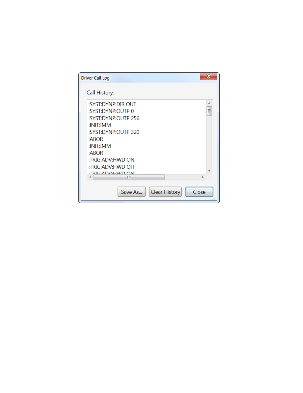
Use this window to inspect the sequence of SCPI commands used to configure the
M8197A module.
It has the following buttons:
Save As…
Saves the Driver Call Log as a text file.
Clear History
Clears the Driver Call Log.
Close
Exits the window.
4.4 Driver Call Log Window
Figure 9 Driver Call Log Window
48 Keysight M8197A User’s Guide
Page 49
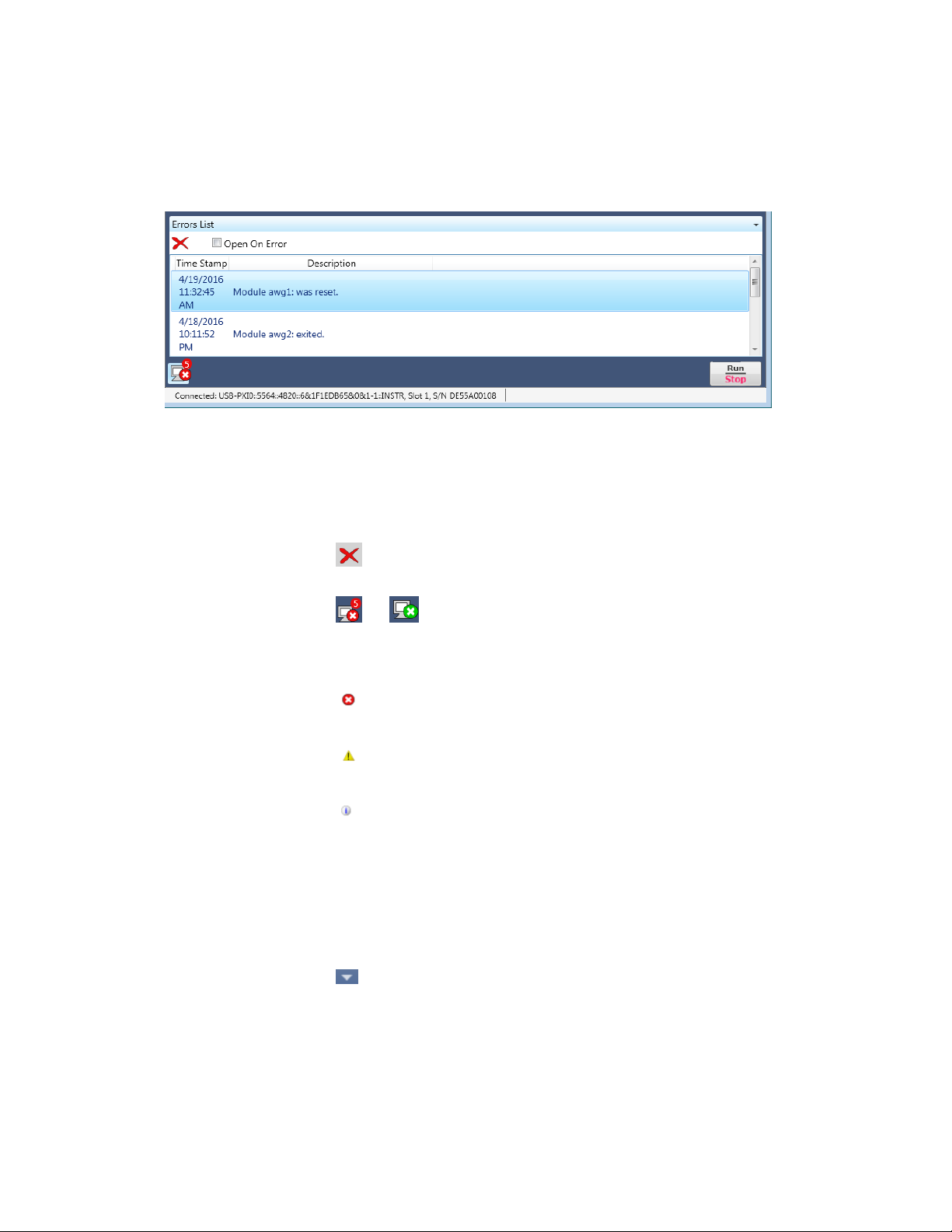
4.5 Errors List Window
Use this window to view errors, warnings, and information.
It has the following controls, signs, and columns:
1. Open On Error
Select this check box to automatically open the errors list window whenever an
error occurs. This window will show error details i.e time stamp and description.
2. (Clear All)
Use this option to clear all the errors from the errors list window.
3. or (Hide Errors List Window or Show Errors List Window)
Use this toggle option to respectively show or hide the errors list window. It also
shows total number of errors in the list. When the window has no errors, the green
tick icon will appear.
4. (Error)
This icon represents an error.
5. (Warning)
This icon represents a warning.
6. (Information)
This icon represents an information.
7. Time Stamp
This column lists the time stamp of individual errors in the format:
DD/MM/YYYY HH:MM:SS.
8. Description
This column provides the description of individual errors.
9. (Window Controls)
This drop down list provides window control options like:
Float
Dock
Auto Hide
Close
Figure 10 Errors List Window
M8197A Soft Front Panel 4
Keysight M8197A User’s Guide 49
Page 50

4 M8197A Soft Front Panel
The module panel allows you to discover available M8195A modules and to define a
multi-module group consisting of up to four slave modules. The VISA resource
strings for available M8195A modules are displayed in a list under column “VISA
Resource”. The drop down list under column “Mode” provides options to specify
whether a module will be part of multi-module group or not. Select “Slave” to add a
module to the multi-module group. The option “None” indicates that the module is
not part of the group. The module tab also allows you to switch between
“Configuration” and “Operation” mode using the “Configuration Mode” check box.
4.6 Module Tab
Figure 11 Module Tab
50 Keysight M8197A User’s Guide
Page 51

M8197A Soft Front Panel 4
It has the following controls:
Discover: Click this button to find the available M8195A modules. The
modules that are found are displayed in the list. The firmware of the
modules to be discovered must be running and the modules must be
entered into the Keysight Connection Expert.
M8195A Module Selection List: It has following columns:
VISA Resource: Displays the visa resource string of the M8195A
module.
Mode: The combo-box in this column can be used to set the multi-
module mode of the module. Select “Slave” to add a module to
synchronization group. The option “None” is used to indicate that the
module is not part of the synchronization group.
Serial Number: Displays the serial number of M8195A module.
Slot Number: Displays the slot number in AXIe chassis.
Chassis: Displays the AXIe chassis information.
Identify: The “Identify” button under this column is used to identify a
module. On clicking this button the access LED of the M8195A module
will be flashed for 10 seconds. This allows easy identification of module
in a setup consisting of multiple AXI frames and multiple modules.
It is recommended to follow the below order when exiting the application:
Stop the system.
Switch to Configuration Mode.
Exit the M8197 Soft Front Panel.
Exit any M8195 Soft Front Panel if necessary.
Exit the M8195 firmware instances if not required any more.
Keysight M8197A User’s Guide 51
Page 52

4 M8197A Soft Front Panel
Use this tab to configure the SYS Clock Out and the Reference Clock of the M8197A
module. It contains switches for internal clock selection and input fields to configure
the relevant frequencies.
Reference clock selection switch
This switch selects between the different reference clock sources.
o Internal: Reference from internal oscillator
o Internal Backplane 100 MHz: Reference from AXIe Backplane
Internal sample frequency
If internal sample clock is selected, this field specifies the frequency of the
internally generated sample clock.
4.7 Clock Tab
Figure 12 Clock Tab
52 Keysight M8197A User’s Guide
Page 53
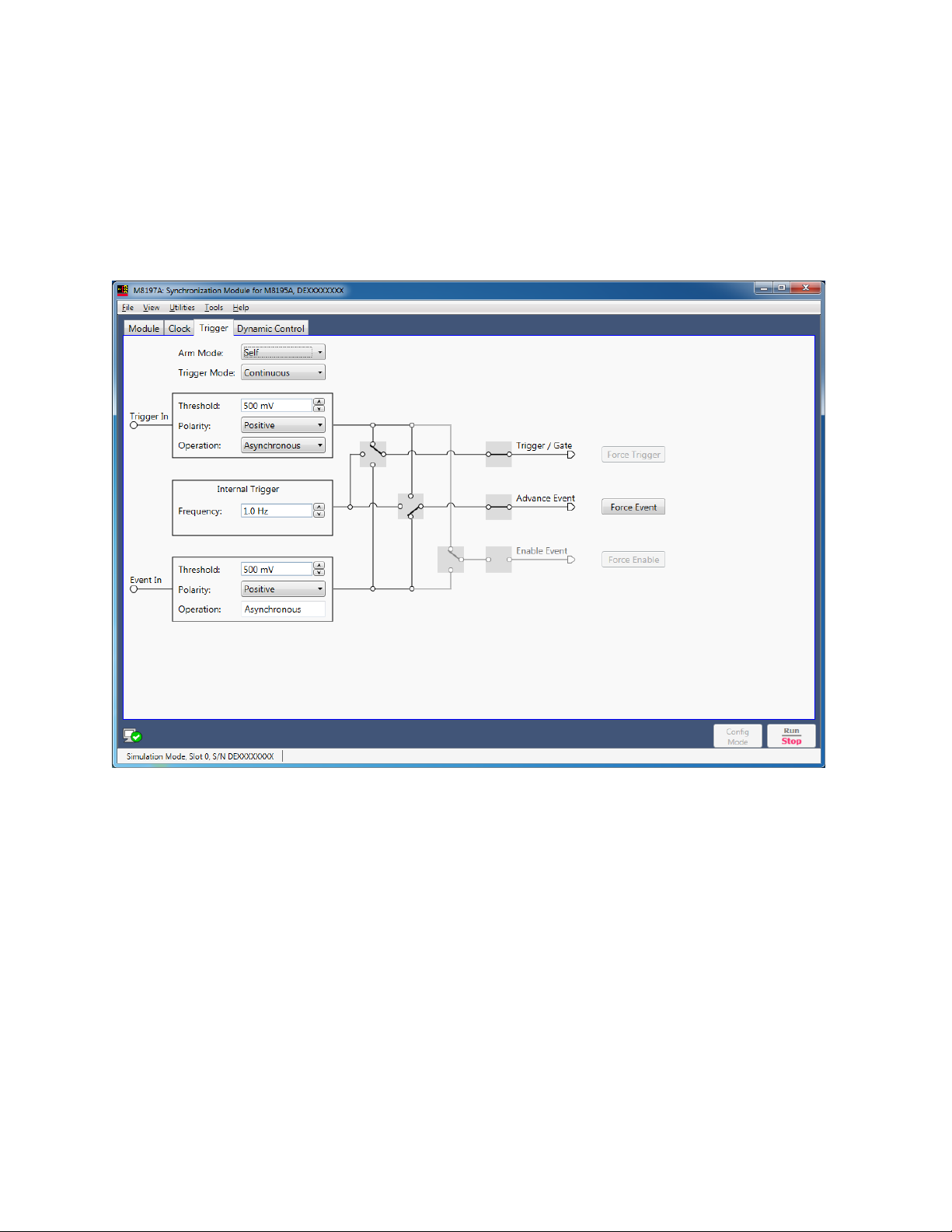
Use this tab to configure the trigger and event input parameters. It allows user to
send software triggers and events to the module.
4.8 Trigger Tab
M8197A Soft Front Panel 4
Figure 13 Trigger Tab
Keysight M8197A User’s Guide 53
Page 54

4 M8197A Soft Front Panel
This tab has the following configurable fields:
Arm mode
o Armed – Signal generation starts when an “enable” event is received.
o Self – Signal generation starts as defined by the trigger mode.
Trigger mode
o Continuous – Signal generation starts immediately after pressing the
Run button. No trigger needed.
o Triggered – Signal generation starts after a trigger is received.
o Gated – Signal generation starts when a rising edge is received on the
trigger input and pauses when a falling edge is received. Signal
generation restarts after the next rising edge.
Threshold
Specifies the threshold voltage for a software trigger or event.
Polarity
Specifies the polarity for a software trigger or event viz. Negative, Positive,
or Either.
Operation
Specifies whether the trigger or event operation is Synchronous or
Asynchronous. Operation mode is same for both trigger and event input.
Frequency
Specifies the frequency for internal trigger.
Force Trigger
Use this button to send a software trigger to a channel.
Force Event
Use this button to send a software event to a channel.
Force Enable
Use this button to send a software “enable” to a channel.
54 Keysight M8197A User’s Guide
Page 55

Use this tab to dynamically control the output by configuring the available set of 13
registers. Hex value of the enabled registers is displayed via the ‘Value’ field.
Registers can be individually enabled by a click, or a hex value can be directly
entered into the ‘Value’ field to enable the desired registers.
4.9 Dynamic Control Tab
M8197A Soft Front Panel 4
Figure 14 Dynamic Control Tab
Keysight M8197A User’s Guide 55
Page 56

4 M8197A Soft Front Panel
Dynamic control has three states:
1. Input
Enables dynamic control for the input.
2. Output
Enables dynamic control for the output.
3. Disabled
Disables dynamic control for both input and output.
Dynamic sequence control has following controls:
Valid Bits
Allows to select valid bits.
Select Sequence:
Allows to select a sequence.
56 Keysight M8197A User’s Guide
Page 57

Keysight M8197A - Synchronization module for M8195A
User’s Guide
5 Remote Programming
5.1 Introduction / 58
5.2 SCPI Programming / 58
5.3 Programming Recommendations / 61
5.4 System Related Commands (SYSTem Subsystem) / 62
5.5 Common Command List / 67
5.6 Status Model / 69
5.7 ARM/TRIGger Subsystem / 76
5.8 TRIGger – Event/Trigger Input / 84
5.9 INSTrument Subsystem / 86
5.10 MMEMory Subsystem / 88
5.11 OUTPut Subsystem / 94
5.12 Sampling Frequency Commands / 95
5.13 Reference Oscillator Commands / 96
5.14 STABle Subsystem / 98
5.15 TEST Subsystem / 98
Page 58

5 Remote Programming
This chapter describes the SCPI commands that are used to program M8197A
module.
The SCPI programming is supported by the following three LAN protocols:
VXI-11: The Visa Resource String is e.g. “TCPIP0::localhost::inst0::INSTR”.
HiSLIP: this protocol is recommended. It offers the functionality of VXI-11
protocol with better performance that is near socket performance. Visa
Resource Strings look like “TCPIP0::localhost::hislip0::INSTR”. The correct
resource string is shown in the M8197A Soft Front Panel’s “About” dialog
under “ VISA Resource String for…”. To use the HiSlip protocol an I/O
library such as the Keysight I/O Libraries Suite must be installed. Since the
protocol is new it might not be supported by the installed I/O library. The
Keysight I/O Libraries Suite 16.1 and above supports it. However, the
Keysight I/O Libraries Suite might be installed as secondary I/O library. In
this case, check if the primary I/O library supports HiSLIP. If it does not, the
socket protocol must be used.
Socket: this protocol can be used with any I/O library or using standard
operating system socket functionality connecting to port 5025. This
protocol must be used if the used I/O library is not supporting HiSLIP
protocol. Visa Resource string looks like
“TCPIP0::localhost::5025::SOCKET”, the exact resource string can be seen
in the M8197A Soft Front Panel’s “About” dialog under “ VISA Resource
String for…”.
AgM8197 Firmare.exe must be started prior to sending SCPI to the instrument. (See
AgM8197SFP.exe)
5.1 Introduction
5.2 SCPI Programming
58 Keysight M8197A User’s Guide
Page 59

5.2.1 AgM8197SFP.exe
The M8197A Software Front Panel and Firmware are one application. You need to
start M8197 Soft Front Panel (AgM8197SFP.exe) before sending SCPI commands to
the instrument. This can be done in the Windows Start menu (Keysight M8197
M8197 Soft Front Panel). You can open the “About” dialog from the M8197A Soft
Front Panel to see the VISA Resource String for the different connection types.
(See Communication for details about /Socket, /Telnet, /Inst, /HiSLIP, /AutoID,
/NoAutoID, /FallBack).
Option
Description
/Socket socketPort
Set the socket port at which the firmware waits for SCPI commands
/Telnet telnetPort
Set the telnet port at which the firmware waits for SCPI commands
/Inst instrumentNumber
Set the instrument number (instN, hislipN) at which the firmware waits for SCPI commands
/HiSLIP hislipNumber
Set the instrument number for HiSLIP SCPI communication. If not specified, the same number as for VXI-11.3
is used.
/AutoID
Automatically select ports and number for the connections (default behavior).
/NoAutoID
Disable the default behavior; i.e. do not automatically select ports and number for the connections.
/FallBack
Try to find unused ports and number if starting a server fails.
/NoSplash
Do not show the splash screen.
/Minimized
Start with the SFP window minimized to the Windows task bar.
/Title “title”
Additional information shown in the SFP window title.
/OutputDir
Set the output directory for the log file and temporary files.
/r resourceName
Visa PXI resource string of the module to connect to, e.g. PXI12::0::0::INSTR. If this is the last parameter on the
command line, the “/r” can be omitted.
/Slave slaveModule
Add an M8195 clock slave module (LAN VISA resource string, i.e. SOCKET, INST, or HiSLIP)
5.2.1.1 Command Line Arguments
Table 9 Command Line Arguments
Remote Programming 5
Keysight M8197A User’s Guide 59
Page 60

5 Remote Programming
Depending on the command line arguments /Socket, /Telnet, /Inst, /AutoID,
/NoAutoID, /FallBack the firmware starts several servers to handle SCPI commands.
(Refer to the table above.)
/Socket, /Telnet, /Inst: If -1, don’t start the respective servers
Defaults:
Socket port: 5025 (e.g. TCPIP0::localhost::5025::SOCKET)
Telnet port: 5024
HiSLIP: 0 (e.g. TCPIP0::localhost::hislip0::INSTR)
VXI-11.3: 0 (TCPIP0::localhost::inst0::INSTR)
/FallBack : If starting a server fails because of a conflict, try using another port or
number
HiSLIP, VXI-11.3: increase the index until a server can be started
successfully
Socket, Telnet: start with the port 60000, then increase it until the servers
can be started successfully. If neither socket nor telnet is disabled the
firmware tries to start the servers on two consecutive ports
(socket port = telnet port + 1)
/AutoID : Automatically select ports and number for the connections, which are
unique per instrument.
This is the default behavior; it is not necessary to specify this argument on
the command line.
If only one AXIe module is connected to this PC and it is an M8197 module,
first try to use the command line arguments /Socket, /Telnet, /Inst or their
respective default values if they are not specified. If starting the servers
fails, proceed with the steps below.
/Socket, /Telnet, /Inst are ignored (unless they are -1 and a server is
disabled)
If the firmware detects more than one AXIe module, use a special
mechanism to obtain a number for the HiSLIP and VXI-11.3 servers, which
makes sure that the firmware uses always the same VISA resource string
per module
The socket and telnet port are then calculated from the HiSLIP index:
telnet port = 60000 + 2 * <HiSLIP index>
socket port = 60000 + 2 * <HiSLIP index> + 1
/NoAutoID : Do not automatically select ports and number for the connections, use
the values specified with /Socket, /Telnet, /Inst or their respective default values
instead.
If both /NoAutoID and /AutoID are specified, /AutoID overrides /NoAutoID.
5.2.1.2 Communication
60 Keysight M8197A User’s Guide
Page 61

This section lists some recommendations for programming the instrument.
Start programming from the default setting. The common command for setting the
default setting is:
*RST
The SCPI standard defines a long and a short form of the commands. For fast
programming speed, it is recommended to use the short forms. The short forms of
the commands are represented by upper case letters. For example the short form of
the command to start/begin event to all channels of the multi-module group is:
: TRIG:BEG
To improve programming speed it is also allowed to skip optional subsystem
command parts. Optional subsystem command parts are depicted in square
brackets, e.g. :TRIGger[:SEQuence][:STARt]:BEGin[:IMMediate]
If it is important to know whether the last command is completed then send the
common query:
*OPC?
It is recommended to test the new setting which will be programmed on the
instrument by setting it up manually. When you have found the correct setting, then
use this to create the program.
In the program it is recommended to send the command for starting data generation
(:INIT:IMM) as the last command. This way intermediate stop/restarts are avoided
and optimum execution performance is achieved.
*RST # set default settings
... # other commands to set modes
... # and parameters
:ARM:TRIG:IMP HIGH # set trigger impedance to High
:INIT:IMM # start data generation.
5.3 Programming Recommendations
Remote Programming 5
Keysight M8197A User’s Guide 61
Page 62

5 Remote Programming
Command
:SYST:ERR?
Long
:SYSTem:ERRor?
Parameters
None
Parameter Suffix
None
Description
Read and clear one error from the instrument’s error queue.
A record of up to 30 command syntax or hardware errors can be stored in the error
queue. Errors are retrieved in first-in-first-out (FIFO) order. The first error returned is
the first error that was stored. Errors are cleared as you read them.
If more than 30 errors have occurred, the last error stored in the queue (the most
recent error) is replaced with “Queue overflow”. No additional errors are stored until
you remove errors from the queue.
If no errors have occurred when you read the error queue, the instrument responds
with 0,“No error”.
The error queue is cleared by the *CLS command, when the power is cycled, or
when the firmware is re-started.
The error queue is not cleared by a reset (*RST) command.
The error messages have the following format (the error string may contain up to 255
characters):
error number,”Description”, e.g.
-113,”Undefined header”.
Example
Query
:SYST:ERR?
Command
:SYST:HELP:HEAD?
Long
:SYSTem:HELP:HEADers?
Parameters
None
Parameter Suffix
None
Description
The HEADers? query returns all SCPI commands and queries and IEEE 488.2 common
commands and common queries implemented by the instrument. The response is a
<DEFINITE LENGTH ARBITRARY BLOCK RESPONSE DATA> element. The full path for
every command and query is returned separated by linefeeds. The syntax of the
response is defined as: The <nonzero digit> and sequence of <digit> follow the rules
in IEEE 488.2, Section 8.7.9. An <SCPI header> is defined as: It contains all the nodes
from the root. The <SCPI program mnemonic> contains the node in standard SCPI
format. The short form uses uppercase characters while the additional characters for
the long form are in lowercase characters. Default nodes are surrounded by square
brackets ([]).
Example
Query
:SYST:HELP:HEAD?
5.4 System Related Commands (SYSTem Subsystem)
5.4.1 :SYSTem:ERRor[:NEXT]?
5.4.2 :SYSTem:HELP:HEADers?
62 Keysight M8197A User’s Guide
Page 63

Command
:SYST:LIC:EXT:LIST?
Long
:SYSTem:LICense:EXTended:LIST?
Parameters
None
Parameter Suffix
None
Description
This query lists the licenses installed.
Example
Query
:SYST:LIC:EXT:LIST?
Command
:SYST:SET[?]
Long
:SYSTem:SET[?]
Parameters
<binary block data>
Parameter Suffix
None
Description
In query form, the command reads a block of data containing the instrument’s
complete set-up. The set-up information includes all parameter and mode settings,
but does not include the contents of the instrument setting memories or the status
group registers. The data is in a binary format, not ASCII, and cannot be edited.
In set form, the block data must be a complete instrument set-up read using the
query form of the command.
This command has the same functionality as the *LRN command.
Example
Command
:SYST:SET <binary block data>
Query
:SYST:SET?
Command
:SYST:VERS?
Long
:SYSTem:VERSion?
Parameters
None
Parameter Suffix
None
Description
This query returns a formatted numeric value corresponding to the SCPI version
number for which the instrument complies, for example “1999.0”.
Example
Query
:SYST:VERS?
5.4.3 :SYSTem:LICense:EXTended:LIST?
5.4.4 :SYSTem:SET[?]
Remote Programming 5
5.4.5 :SYSTem:VERSion?
Keysight M8197A User’s Guide 63
Page 64

5 Remote Programming
These queries return information about the instrument firmware’s available
connections. If a connection is not available the returned value is -1.
This is only useful if there is more than one Keysight module connected to a PC,
otherwise one would normally use the default connections (HiSLIP and VXI-11
instrument number 0, socket port 5025, telnet port 5024)
One can never be sure if a socket port is already in use, so one could e.g. specify a
HiSLIP number on the command line (AgM8197Firmware.exe /AutoID /i 5
/FallBack /r …) and let the firmware find an unused socket port. Then this
socket port can be queried using the HiSLIP connection.
Command
:SYST:COMM:INST?
Long
:SYSTem:COMMunicate:INSTr?
Parameters
None
Parameter Suffix
None
Description
This query returns the VXI-11 instrument number used by the firmware.
Example
Query
:SYST:COMM:INST?
Command
:SYST:COMM:HISL?
Long
:SYSTem:COMMunicate:HISLip?
Parameters
None
Parameter Suffix
None
Description
This query returns the HiSLIP number used by the firmware.
Example
Query
:SYST:COMM:HISL?
Command
:SYST:COMM:SOCK?
Long
:SYSTem:COMMunicate:SOCKet?
Parameters
None
Parameter Suffix
None
Description
This query returns the socket port used by the firmware.
Example
Query
:SYST:COMM:SOCK?
5.4.6 :SYSTem:COMMunicate:*?
5.4.6.1 :SYSTem:COMMunicate:INSTr[:NUMBer]?
5.4.6.2 :SYSTem:COMMunicate:HISLip[:NUMBer]?
5.4.6.3 :SYSTem:COMMunicate:SOCKet[:PORT]?
64 Keysight M8197A User’s Guide
Page 65

5.4.6.4 :SYSTem:COMMunicate:TELNet[:PORT]?
Command
:SYST:COMM:TELN?
Long
:SYSTem:COMMunicate:TELNet?
Parameters
None
Parameter Suffix
None
Description
This query returns the telnet port used by the firmware.
Example
Query
:SYST:COMM:TELN?
Remote Programming 5
Keysight M8197A User’s Guide 65
Page 66

5 Remote Programming
Command
:SYST:DYNP:DIR[?]
Long
:SYSTem:DYNPort:DIRection[?]
Parameters
DISabled|INPut|OUTPut
Parameter Suffix
None
Description
Set or query the signal direction of the dynamic control interface.
DISabled – interface is disabled
INPut – interface is used for dynamic control / GPIO in
OUTPut – interface is used for GPIO out
Example
Command
:SYST:DYNP:DIR OUTP
Query
:SYST:DYNP:DIR?
Command
:SYST:DYNP:OUTP[?]
Long
:SYSTem:DYNPort:OUTPut[?]
Parameters
<value>|MINimum|MAXimum
Parameter Suffix
None
Description
Set or query the state of the 13 data pins in the dynamic control interface.
Example
Command
:SYST:DYNP:OUTP 0x1234
Query
:SYST:DYNP:OUTP?
Command
:SYST:DYNP:OUTP:PIN[?]
Long
:SYSTEM:DYNPort:OUTPut:PIN[?]
Parameters
<pin>,0|1|OFF|ON
Parameter Suffix
None
Description
Set or query the state of a single data pin in the dynamic control interface.
Example
Command
:SYST:DYNP:OUTP:PIN 12,ON
Query
:SYST:DYNP:OUTP:PIN? 12
5.4.7 :SYSTem:DYNPort:*
5.4.7.1 :SYSTem:DYNPort:DIRection[?] DISabled|INPut|OUTPut
:
5.4.7.2 SYSTem:DYNPort:OUTPut[?] <value>|MINimum|MAXimum
5.4.7.3 :SYSTem:DYNPort:OUTPut:PIN[?] <pin>,0|1|OFF|ON
66 Keysight M8197A User’s Guide
Page 67

Read the instrument’s identification string, which contains four fields separated by
commas. The first field is the manufacturer’s name, the second field is the model
number, the third field is the serial number, and the fourth field is a revision code
which contains four numbers separated dots and a fifth number separated by a dash:
Keysight Technologies, M8197A,<serial number>, x.x.x.x-h
x.x.x.x= Firmware revision number, e.g. 2.0.0.0
h= Hardware revision number
Clear the event register in all register groups. This command also clears the error
queue and cancels a *OPC operation. It doesn’t clear the enable register.
Enable bits in the Standard Event Status Register to be reported in the Status Byte.
The selected bits are summarized in the “Standard Event” bit (bit 5) of the Status
Byte Register. The *ESE? query returns a value which corresponds to the binaryweighted sum of all bits enabled decimal by the *ESE command. These bits are not
cleared by a *CLS command. Value Range: 0–255.
Query the Standard Event Status Register. Once a bit is set, it remains set until
cleared by a *CLS (clear status) command or queried by this command. A query of
this register returns a decimal value which corresponds to the binary-weighted sum
of all bits set in the register.
Set the “Operation Complete” bit (bit 0) in the Standard Event register after the
previous commands have been completed.
Return “1” to the output buffer after the previous commands have been completed.
Other commands cannot be executed until this command completes.
5.5 Common Command List
5.5.1 *IDN?
5.5.2 *CLS
Remote Programming 5
5.5.3 *ESE
5.5.4 *ESR?
5.5.5 *OPC
5.5.6 *OPC?
Keysight M8197A User’s Guide 67
Page 68

5 Remote Programming
Read the installed options. The response consists of any number of fields separated
by commas.
Reset instrument to its factory default state.
Enable bits in the Status Byte to generate a Service Request. To enable specific bits,
you must write a decimal value which corresponds to the binary-weighted sum of the
bits in the register. The selected bits are summarized in the “Master Summary” bit
(bit 6) of the Status Byte Register. If any of the selected bits change from “0” to “1”, a
Service Request signal is generated. The *SRE? query returns a decimal value which
corresponds to the binary-weighted sum of all bits enabled by the *SRE command.
Query the summary (status byte condition) register in this register group. This
command is similar to a Serial Poll but it is processed like any other instrument
command. This command returns the same result as a Serial Poll but the “Master
Summary” bit (bit 6) is not cleared by the *STB? command.
Execute Self Tests. If self-tests pass, a 0 is returned. A number lager than 0
indicates the number of failed tests.
To get actual messages, use :TEST:TST?
Query the instrument and return a binary block of data containing the current
settings (learn string). You can then send the string back to the instrument to restore
this state at a later time. For proper operation, do not modify the returned string
before sending it to the instrument. Use :SYST:SET to send the learn string. See
section 5.4.4.
Prevents the instrument from executing any further commands until the current
command has finished executing.
5.5.7 *OPT?
5.5.8 *RST
5.5.9 *SRE[?]
5.5.10 *STB?
5.5.11 *TST?
5.5.12 *LRN?
5.5.13 *WAI
68 Keysight M8197A User’s Guide
Page 69

Introduction
This section describes the structure of the SCPI status system used by the M8197A.
The status system records various conditions and states of the instrument in several
register groups as shown on the following pages. Each of the register groups is made
up of several low level registers called Condition registers, Event registers, and
Enable registers which control the action of specific bits within the register group.
These groups are explained below:
A condition register continuously monitors the state of the instrument. The
bits in the condition register are updated in real time and the bits are not
latched or buffered. This is a read-only register and bits are not cleared
when you read the register. A query of a condition register returns a
decimal value which corresponds to the binary-weighted sum of all bits set
in that register.
An event register latches the various events from changes in the condition
register. There is no buffering in this register; while an event bit is set,
subsequent events corresponding to that bit are ignored. This is a read only
register. Once a bit is set, it remains set until cleared by query command
(such as STAT:QUES:EVEN?) or a *CLS (clear status) command. A query
of this register returns a decimal value which corresponds to the binaryweighted sum of all bits set in that register.
An enable register defines which bits in the event register will be reported
to the Status Byte register group. You can write to or read from an enable
register. A *CLS (clear status) command will not clear the enable register
but it does clear all bits in the event register. A STAT:PRES command
clears all bits in the enable register. To enable bits in the enable register to
be reported to the Status Byte register, you must write a decimal value
which corresponds to the binary weighted sum of the corresponding bits.
Transition Filters are used to detect changes of the state in the condition
register and set the corresponding bit in the event register. You can set
transition filter bits to detect positive transitions (PTR), negative transitions
(NTR) or both. Transition filters are read/write registers. They are not
affected by *CLS.
5.6 Status Model
Remote Programming 5
Keysight M8197A User’s Guide 69
Page 70

5 Remote Programming
Figure 15 Status Register Structure
70 Keysight M8197A User’s Guide
Page 71

5.6.1 :STATus:PRESet
Clears all status group event registers. Presets the status group enables PTR and
NTR registers as follows:
ENABle = 0x0000, PTR = 0xffff, NTR = 0x0000
The Status Byte summary register reports conditions from the other status registers.
Data that is waiting in the instrument’s output buffer is immediately reported on the
“Message Available” bit (bit 4) for example. Clearing an event register from one of the
other register groups will clear the corresponding bits in the Status Byte condition
register. Reading all messages from the output buffer, including any pending queries,
will clear the “Message Available” bit. To set the enable register mask and generate
an SRQ (service request), you must write a decimal value to the register using the
*SRE command.
Bit Number
Decimal Value
Definition
0 Not used
1
Not Used. Returns “0”
1 Not used
2
Not Used. Returns “0”
2 Error Queue
4
One or more error are stored in the Error Queue
3 Questionable Data
8
One or more bits are set in the Questionable Data Register (bits must be
enabled)
4 Message Available
16
Data is available in the instrument’s output buffer
5 Standard Event
32
One or more bits are set in the Standard Event Register
6 Master Summary
64
One or more bits are set in the Status Byte Register
7 Operational Data
128
One or more bits set in the Operation Data Register (bits must be enabled)
5.6.2 Status Byte Register
Table 10 Status Byte Register
Remote Programming 5
Keysight M8197A User’s Guide 71
Page 72

5 Remote Programming
The Questionable Data register group provides information about the quality or
integrity of the instrument. Any or all of these conditions can be reported to the
Questionable Data summary bit through the enable register.
Bit Number
Decimal Value
Definition
0 SYSClock Status warning
1
One or multiple system clock outputs have been switched off
(to protect themselves).
1 Not used
2
Returns “0”
2 Not used
4
Returns “0”
3 Not used
8
Returns “0”
4 Not used
16
Returns “0”
5 Not used
32
Returns “0”
6 Not used
64
Returns “0”
7 Not used
128
Returns “0”
8 Not used
256
Returns “0”
9 Not used
512
Returns “0”
10 Not used
1024
Returns “0”
11 Not used
2048
Returns “0”
12 Not used
4096
Returns “0”
13 Not used
8192
Returns “0”
14 Not used
16384
Returns “0”
15 Not used
32768
Returns “0”
The following commands access the questionable status group.
Reads the event register in the questionable status group. It’s a read-only register.
Once a bit is set, it remains set until cleared by this command or the *CLS
command. A query of the register returns a decimal value which corresponds to the
binary-weighted sum of all bits set in the register.
Reads the condition register in the questionable status group. It’s a read-only
register and bits are not cleared when you read the register. A query of the register
returns a decimal value which corresponds to the binary-weighted sum of all bits set
in the register.
5.6.3 Questionable Data Register Command Subsystem
Table 11 Questionable Data Register
5.6.3.1 :STATus:QUEStionable[:EVENt]?
5.6.3.2 :STATus:QUEStionable:CONDition?
72 Keysight M8197A User’s Guide
Page 73

5.6.3.3 :STATus:QUEStionable:ENABle[?]
Sets or queries the enable register in the questionable status group. The selected
bits are then reported to the Status Byte. A *CLS will not clear the enable register
but it does clear all bits in the event register. To enable bits in the enable register,
you must write a decimal value which corresponds to the binary-weighted sum of the
bits you wish to enable in the register.
Sets or queries the negative-transition register in the questionable status group. A
negative transition filter allows an event to be reported when a condition changes
from true to false. Setting both positive/negative filters true allows an event to be
reported anytime the condition changes. Clearing both filters disable event reporting.
The contents of transition filters are unchanged by *CLS and *RST.
Set or queries the positive-transition register in the questionable status group. A
positive transition filter allows an event to be reported when a condition changes
from false to true. Setting both positive/negative filters true allows an event to be
reported anytime the condition changes. Clearing both filters disable event reporting.
The contents of transition filters are unchanged by *CLS and *RST.
5.6.3.4 :STATus:QUEStionable:NTRansition[?]
Remote Programming 5
5.6.3.5 :STATus:QUEStionable:PTRansition[?]
Keysight M8197A User’s Guide 73
Page 74

5 Remote Programming
The Operation Status register contains conditions which are part of the instrument’s
normal operation.
Bit Number
Decimal Value
Definition
0 Not used
1
Returns “0”
1 Not used
2
Returns “0”
2 Not used
4
Returns “0”
3 Not used
8
Returns “0”
4 Not used
16
Returns “0”
5 Not used
32
Returns “0”
6 Not used
64
Returns “0”
7 Not used
128
Returns “0”
8 Run Status
256
Indicates if the multi-module group is in running/armed state
(:INIT:IMM was executed).
9 Not used
512
Returns “0”
10 Not used
1024
Returns “0”
11 Not used
2048
Returns “0”
12 Not used
4096
Returns “0”
13 Not used
8192
Returns “0”
14 Not used
16384
Returns “0”
15 Not used
32768
Returns “0”
The following commands access the operation status group.
Reads the event register in the operation status group. It’s a read-only register. Once
a bit is set, it remains set until cleared by this command or *CLS command. A query
of the register returns a decimal value which corresponds to the binary-weighted
sum of all bits set in the register.
Reads the condition register in the operation status group. It’s a read-only register
and bits are not cleared when you read the register. A query of the register returns a
decimal value which corresponds to the binary-weighted sum of all bits set in the
register.
5.6.4 Operation Status Subsystem
Table 12 Operation Status Register
5.6.4.1 :STATus:OPERation[:EVENt]?
5.6.4.2 :STATus:OPERation:CONDition?
74 Keysight M8197A User’s Guide
Page 75

Sets or queries the enable register in the operation status group. The selected bits
are then reported to the Status Byte. A *CLS will not clear the enable register but it
does clear all bits in the event register. To enable bits in the enable register, you
must write a decimal value which corresponds to the binary-weighted sum of the bits
you wish to enable in the register.
Sets or queries the negative-transition register in the operation status group. A
negative transition filter allows an event to be reported when a condition changes
from true to false. Setting both positive/negative filters true allows an event to be
reported anytime the condition changes. Clearing both filters disable event reporting.
The contents of transition filters are unchanged by *CLS and *RST.
Set or queries the positive-transition register in the operation status group. A positive
transition filter allows an event to be reported when a condition changes from false
to true. Setting both positive/negative filters true allows an event to be reported
anytime the condition changes. Clearing both filters disable event reporting. The
contents of transition filters are unchanged by *CLS and *RST.
The Run Status register contains the run status conditions of the multi-module
group.
The following SCPI commands and queries are supported:
:STATus:OPERation:RUN[:EVENt]?
:STATus:OPERation:RUN:CONDition?
:STATus:OPERation:RUN:ENABle[?]
:STATus:OPERation:RUN:NTRansition[?]
:STATus:OPERation:RUN:PTRansition[?]
Bit Number
Decimal Value
Definition
0 Run Status
1
Indicates if the multi-module group is in
running/armed state (:INIT:IMM was executed).
5.6.4.3 :STATus:OPERation:ENABle[?]
5.6.4.4 :STATus:OPERation:NTRansition[?]
Remote Programming 5
5.6.4.5 :STATus:OPERation:PTRansition[?]
5.6.5 Run Status Subsystem
Table 13 Run Status Register
Keysight M8197A User’s Guide 75
Page 76

5 Remote Programming
Command
:ABOR
Long
:ABORt
Parameters
None
Parameter Suffix
None
Description
Stop signal generation on all channels of the multi-module group.
Example
Command
:ABOR
Command
:INIT:CONT:ENAB[?]
Long
:INITiate:CONTinuous:ENABle[?]
Parameters
SELF|ARMed
Parameter Suffix
None
Description
Set or query the arming mode.
Example
Command
:INIT:CONT:ENAB SELF
Query
:INIT:CONT:ENAB?
Command
:INIT:CONT:[STAT][?]
Long
:INITiate:CONTinuous:[STATe][?]
Parameters
OFF | ON | 0 | 1
Parameter Suffix
None
Description
Set or query the continuous mode. This command must be used together with
INIT:GATE to set the trigger mode.
0/OFF – Continuous mode is off. If gate mode is off, the trigger mode is “triggered”,
else it is “gated”.
1/ON – Continuous mode is on. Trigger mode is “automatic”. The value of gate mode
is not relevant.
Example
Command
:INIT:CONT:STAT ON
Query
:INIT:CONT:STAT?
5.7 ARM/TRIGger Subsystem
5.7.1 :ABORt
5.7.2 :INITiate:CONTinuous:ENABle[?] SELF|ARMed
5.7.3 :INITiate:CONTinous[:STATe][?] OFF|ON|0|1
76 Keysight M8197A User’s Guide
Page 77

5.7.4 :INITiate:GATE[:STATe][?] OFF|ON|0|1
Command
:INIT:GATE:[STAT][?]
Long
:INITiate:GATE:[STATe][?]
Parameters
OFF | ON | 0 | 1
Parameter Suffix
None
Description
Set or query the gate mode. This command must be used together with INIT:CONT
to set the trigger mode.
0/OFF – Gate mode is off.
1/ON – Gate mode is on. If continuous mode is off, the trigger mode is “gated”.
Example
Command
:INIT:GATE:STAT ON
Query
:INIT:GATE:STAT?
INIT:CONT
INIT:GATE
Trigger Mode
0 0 Triggered
0 1 Gated 1 0
Continuous
1 1 Continuous
Command
:INIT:IMM
Long
:INITiate:IMMediate
Parameters
None
Parameter Suffix
None
Description
Set all channels of the multi-module group to an armed state. Signal generation is
started after a trigger is received.
Example
Command
:INIT:IMM
Table 14: Trigger mode settings
Remote Programming 5
5.7.5 :INITiate:IMMediate
Keysight M8197A User’s Guide 77
Page 78

5 Remote Programming
Command
:ARM[:SEQ][:STAR][:LAY]:TRIG:LEV[?]
Long
:ARM[:SEQuence][:STARt][:LAYer]:TRIGger:LEVel[?]
Parameters
<level>|MINimum|MAXimum
Parameter Suffix
Volt (V) or millivolt (mV)
Description
Set or query the threshold level of the M8197A trigger input.
<level> – Threshold level voltage.
Example
Command
:ARM:TRIG:LEV 3e-9
Query
:ARM:TRIG:LEV?
Command
:ARM[:SEQ][:STAR][:LAY]:TRIG:SLOP[?]
Long
:ARM[:SEQuence][:STARt][:LAYer]:TRIGger:SLOPe[?]
Parameters
POSitive|NEGative|EITHer
Parameter Suffix
None
Description
Set or query the trigger input slope.
POSitive – rising edge
NEGative – falling edge
EITHer – both
Example
Command
:ARM:TRIG:SLOP POS
Query
:ARM:TRIG:SLOP?
5.7.6 :ARM[:SEQuence][:STARt][:LAYer]:TRIGger:LEVel[?] <level>|MINimum|MAXimum
5.7.7 :ARM[:SEQuence][:STARt][:LAYer]:TRIGger:SLOPe[?] POSitive|NEGative|EITHer
78 Keysight M8197A User’s Guide
Page 79

Remote Programming 5
Command
:ARM[:SEQ][:STAR][:LAY]:TRIG:SOUR[?]
Long
:ARM[:SEQuence][:STARt][:LAYer]:TRIGger:SOURce[?]
Parameters
TRIGger|EVENt|INTernal
Parameter Suffix
None
Description
Set or query the source for the trigger function.
TRIGger - trigger input
EVENt - event input
INTernal – internal trigger generator
Example
Command
:ARM:TRIG:SOUR TRIG
Query
:ARM:TRIG:SOUR?
Command
:ARM[:SEQ][:STAR][:LAY]:TRIG:FREQ[?]
Long
:ARM[:SEQuence][:STARt][:LAYer]:TRIGger:FREQuency[?]
Parameters
<frequency>|MINimum|MAXimum
Parameter Suffix
None
Description
Set or query the frequency of the internal trigger generator.
<frequency> – internal trigger frequency
Example
Command
:ARM:TRIG:FREQ 1
Query
:ARM:TRIG:FREQ?
5.7.8 :ARM[:SEQuence][:STARt][:LAYer]:TRIGger:SOURce[?] TRIGger|EVENt|INTernal
5.7.9 :ARM[:SEQuence][:STARt][:LAYer]:TRIGger:FREQuency[?]
<frequency>|MINimum|MAXimum
Keysight M8197A User’s Guide 79
Page 80

5 Remote Programming
Command
:ARM[:SEQ][:STAR][:LAY]:TRIG:OPER[?]
Long
:ARM[:SEQuence][:STARt][:LAYer]:TRIGger:OPERation[?]
Parameters
ASYNchronous|SYNChronous
Parameter Suffix
None
Description
Set or query the M8197A’s trigger operation mode.
Example
Command
:ARM:TRIG:OPER SYNC
Query
:ARM:TRIG:OPER?
Command
:ARM[:SEQ][:STAR][:LAY]:EVEN:LEV[?]
Long
:ARM[:SEQuence][:STARt][:LAYer]:EVENt:LEVel[?]
Parameters
<level>|MINimum|MAXimum
Parameter Suffix
Volt (V) or millivolt (mV)
Description
Set or query the threshold level of the M8197A event input.
<level> – Threshold level voltage.
Example
Command
:ARM:EVEN:LEV 3e-9
Query
:ARM:EVEN:LEV?
Command
:ARM[:SEQ][:STAR][:LAY]:EVEN:SLOP[?]
Long
:ARM[:SEQuence][:STARt][:LAYer]:EVENt:SLOPe[?]
Parameters
POSitive|NEGative|EITHer
Parameter Suffix
None
Description
Set or query the event input slope.
POSitive – rising edge
NEGative – falling edge
EITHer – both
Example
Command
:ARM:EVEN:SLOP POS
Query
:ARM:EVEN:SLOP?
5.7.10 :ARM [:SEQuence][:STARt][:LAYer]:TRIGger:OPERation[?]
ASYNchronous|SYNChronous
5.7.11 :ARM[:SEQuence][:STARt][:LAYer]:EVENt:LEVel[?] <level>|MINimum|MAXimum
5.7.12 :ARM[:SEQuence][:STARt][:LAYer]:EVENt:SLOPe[?] POSitive|NEGative|EITHer
80 Keysight M8197A User’s Guide
Page 81

Remote Programming 5
Command
:ARM:DYNP:WIDT[?]
Long
:ARM:DYNPort:WIDTh[?]
Parameters
LOWerbits|ALLBits
Parameter Suffix
None
Description
Use this command to set or query the number of valid bits of the dynamic control input.
The input connector has 13 data pins Data_In[0..12], a Data_Select and a Load pin.
Internally, 24 bits of data are used, which are multiplexed using Data_Select.
Data_In[0..12] and Data_Select will be stored on rising edge of Load signal.
LOWerbits – 13 Bits are used to select a segment dynamically. Data_Select = Low:
Data[0..12] = Data_In[0..12]. Data[13..24] = 0.
ALLBits – 24 Bits are used to select a segment dynamically. Data_Select = Low:
Data[0..12] = Data_In[0..12]. Data_Select = High: Data[13..24] = Data_In[0..10].
Example
Command
:ARM:DYNP:WIDT ALLB
Query
:ARM:DYNP:WIDT?
Command
:TRIG[:SEQ][:STAR]:SOUR:ENAB[?]
Long
:TRIGger[:SEQuence][:STARt]:SOURce:ENABle[?]
Parameters
TRIGger|EVENt
Parameter Suffix
None
Description
Set or query the source for the enable event.
TRIGger - trigger input
EVENt - event input
Example
Command
:TRIG:SOUR:ENAB TRIG
Query
:TRIG:SOUR:ENAB?
5.7.13 :ARM[:SEQuence][:STARt][:LAYer]:DYNPort:WIDTh[?] LOWerbits|ALLBits
5.7.14 :TRIGger[:SEQuence][:STARt]:SOURce:ENABle[?] TRIGger|EVENt
Keysight M8197A User’s Guide 81
Page 82

5 Remote Programming
Command
:TRIG[:SEQ][:STAR]:ENAB:HWD[?]
Long
:TRIGger[:SEQuence][:STARt]:ENABle:HWDisable[?]
Parameters
0|1|OFF|ON
Parameter Suffix
None
Description
Set or query the hardware input disable state for the enable function. When the
hardware input is disabled, an enable event can only be generated using the
:TRIGger[:SEQuence][:STARt]:ENABle[:IMMediate] command. When the hardware
input is enabled, an enable event can be generated by command or by a signal present
at the trigger or event input.
Example
Command
:TRIG:ENAB:HWD ON
Query
:TRIG:ENAB:HWD?
Command
:TRIG[:SEQ][:STAR]:BEG:HWD[:STAT][?]
Long
:TRIGger[:SEQuence][:STARt]:BEGin:HWDisable[:STATe][?]
Parameters
0|1|OFF|ON
Parameter Suffix
None
Description
Set or query the M8197A’s hardware input disable state for the trigger function.
When the hardware input is disabled, a trigger can only be generated using the
:TRIGger[:SEQuence][:STARt]:BEGin[:IMMediate] command. When the hardware
input is enabled, a trigger can be generated by command or by a signal present at
the trigger input of the M8197A.
Example
Command
:TRIG:BEG:HWD ON
Query
:TRIG:BEG:HWD?
5.7.15 :TRIGger[:SEQuence][:STARt]:ENABle:HWDisable[:STATe][?]
0|1|OFF|ON
5.7.16 :TRIGger[:SEQuence][:STARt]:BEGin:HWDisable[:STATe][?] 0|1|OFF|ON
82 Keysight M8197A User’s Guide
Page 83

Command
:TRIG[:SEQ][:STAR]:ADV:HWD[?]
Long
:TRIGger[:SEQuence][:STARt]:ADVance:HWDisable[?]
Parameters
0|1|OFF|ON
Parameter Suffix
None
Description
Set or query the hardware input disable state for the advancement function. When the
hardware input is disabled, an advancement event can only be generated using the
:TRIGger[:SEQuence][:STARt]:ADVance[:IMMediate] command. When
the hardware input is enabled, an advancement event can be generated by command
or by a signal present at the trigger or event input.
Example
Command
:TRIG:ADV:HWD 0
Query
:TRIG:ADV:HWD?
5.7.17 :TRIGger[:SEQuence][:STARt]:ADVance:HWDisable[:STATe][?]
0|1|OFF|ON
Remote Programming 5
Keysight M8197A User’s Guide 83
Page 84

5 Remote Programming
Command
:TRIG[:SEQ][:STAR]:SOUR:ADV[?]
Long
:TRIGger[:SEQuence][:STARt]:SOURce:ADVance[?]
Parameters
TRIGger|EVENt|INTernal
Parameter Suffix
None
Description
Set or query the source for the advancement event.
TRIGger - trigger input
EVENt - event input
INTernal – internal trigger generator
Example
Command
:TRIG:SOUR:ADV TRIG
Query
:TRIG:SOUR:ADV?
Command
:TRIG[:SEQ][:STAR]:ENAB
Long
:TRIGger[:SEQuence][:STARt]:ENABle
Parameters
None
Parameter Suffix
None
Description
Send the enable event to a channel.
Example
Command
:TRIG:ENAB
Command
:TRIG[:SEQ][:STAR]:BEG[:IMM]
Long
:TRIGger[:SEQuence][:STARt]:BEGin[:IMMediate]
Parameters
None
Parameter Suffix
None
Description
Send the start/begin event to all channels of the multi-module group.
Example
Command
:TRIG:BEG
5.8 TRIGger – Event/Trigger Input
5.8.1 :TRIGger[:SEQuence][:STARt]:SOURce:ADVance[?] TRIGger|EVENt|INTernal
5.8.2 :TRIGger[:SEQuence][:STARt]:ENABle[:IMMediate]
5.8.3 :TRIGger[:SEQuence][:STARt]:BEGin[:IMMediate]
84 Keysight M8197A User’s Guide
Page 85

Command
:TRIG[:SEQ][:STAR]:BEG:GATE[?]
Long
:TRIGger[:SEQuence][:STARt]:BEGin:GATE[?]
Parameters
OFF|ON|0|1
Parameter Suffix
None
Description
In gated mode send a “gate open” (ON|1) or “gate close” (OFF|0) to a channel.
Example
Command
:TRIG:BEG:GATE ON
Query
:TRIG:BEG:GATE?
Command
:TRIG[:SEQ][:STAR]:ADV
Long
:TRIGger[:SEQuence][:STARt]:ADVance
Parameters
None
Parameter Suffix
None
Description
Send the advancement event to a channel.
Example
Command
:TRIG:ADV
5.8.4 TRIGger[:SEQuence][:STARt]:BEGin:GATE[:STATe][?] OFF|ON|0|1
5.8.5 :TRIGger[:SEQuence][:STARt]:ADVance[:IMMediate]
Remote Programming 5
Keysight M8197A User’s Guide 85
Page 86

5 Remote Programming
Command
:INST:SLOT[:NUMB]?
Long
:INSTrument:SLOT[:NUMBer]?
Parameters
None
Parameter Suffix
None
Description
Query the instrument’s slot number in its AXIe frame.
Example
Query
:INST:SLOT?
These commands and queries are used to identify reachable M8195A modules and to
define a multi-module group consisting of up to four slave modules.
Command
:INST:MDIS?
Long
:INSTrument:MDIScover?
Parameters
None
Parameter Suffix
None
Description
This query returns a comma-separated list of VISA resource strings of all M8195A
modules known by the VISA Resource Manager.
Example
Query
:INST:MDIS?
Command
:INST:IDEN
Long
:INSTrument:IDENtify
Parameters
<visa_resource_string>
Parameter Suffix
None
Description
This command toggles the green “Access” LED of the M8195 module with the passed
VISA resource string for 10 seconds. This allows easy identification of one module in a
setup consisting of multiple AXI frames and multiple modules.
Example
Command
:INST:IDEN “TCPIP0::localhost::hislip0::INSTR”
5.9 INSTrument Subsystem
5.9.1 :INSTrument:SLOT[:NUMBer]?
5.9.2 Multi-module configuration commands
5.9.2.1 :INSTrument:MDIScover?
5.9.2.2 :INSTrument:IDENtify <visa_resource_string>
86 Keysight M8197A User’s Guide
Page 87

5.9.2.3 :INSTrument: SLAVe:LIST?
Command
:INST:SLAV:LIST?
Long
:INSTrument:SLAVe:LIST?
Parameters
None
Parameter Suffix
None
Description
This query returns a comma-separated list of VISA resource strings of all M8195A
slave modules that belong to the multi-module group.
Example
Query
:INST:SLAV:LIST?
Command
:INST:MMOD:CONF[?]
Long
:INSTrument:MMODule:CONFig[?]
Parameters
0|1|OFF|ON
Parameter Suffix
None
Description
The command form enables (1|ON) or disables (0|OFF) the multi-module configuration
mode for the complete multi-module group. The command forms of the following
SCPIs for slave selection are only available in multi-module configuration mode. When
the multi-module configuration mode is disabled, the modifications become active.
The query form returns the state of the multi-module configuration mode.
Example
Command
:INST:MMOD:CONF ON
Query
:INST:MMOD:CONF?
Command
:INST:SLAV:ADD
Long
:INSTrument:SLAVe:ADD
Parameters
< visa_resource_string>
Parameter Suffix
None
Description
This command adds the M8195A module with the passed VISA resource string as slave
to the multi-module group.
Example
Command
:INST:SLAV:ADD “TCPIP0::localhost::hislip0::INSTR”
Command
:INST:SLAV:DEL
Long
:INSTrument:SLAVe:DELete
5.9.2.4 :INSTrument:MMODule:CONFig[?] 0|1|OFF|ON
Remote Programming 5
5.9.2.5 :INSTrument:SLAVe:ADD < visa_resource_string>
5.9.2.6 :INSTrument: SLAVe:DELete < visa_resource_string>
Keysight M8197A User’s Guide 87
Page 88

5 Remote Programming
Parameters
< visa_resource_string>
Parameter Suffix
None
Description
This command deletes the M8195A slave module with the passed VISA resource string
from the multi-module group.
Example
Command
:INST:SLAV:DEL “TCPIP0::localhost::hislip0::INSTR”
Command
:INST:SLAV:DEL:ALL
Long
:INSTrument:SLAVe:DELete:ALL
Parameters
None
Parameter Suffix
None
Description
This command deletes all M8195A slave modules from the multi-module group.
Example
Command
:INST:SLAV:DEL:ALL
MMEM commands requiring <directory_name> assume the current directory if a
relative path or no path is provided. If an absolute path is provided, then it is ignored.
5.9.2.7 :INSTrument: SLAVe:DELete:ALL
5.10 MMEMory Subsystem
88 Keysight M8197A User’s Guide
Page 89

Command
:MMEM:CAT?
Long
:MMEMory:CATalog?
Parameters
None
Parameter Suffix
None
Description
Query disk usage information (drive capacity, free space available) and obtain a list of
files and directories in a specified directory in the following format:
<numeric_value>,<numeric_value>,{<file_entry>}
This command returns two numeric parameters and as many strings as there are files
and directories. The first parameter indicates the total amount of storage currently
used in bytes. The second parameter indicates the total amount of storage available,
also in bytes. The <file_entry> is a string. Each <file_entry> indicates the name, type,
and size of one file in the directory list:
<file_name>,<file_type>,<file_size>
As the Windows file system has an extension that indicates file type, <file_type> is
always empty. <file_size> provides the size of the file in bytes. In case of directories,
<file_entry> is surrounded by square brackets and both <file_type> and <file_size>
are empty.
Example
Query
:MMEM:CAT?
5.10.1 :MMEMory:CATalog? [<directory_name>]
Remote Programming 5
Keysight M8197A User’s Guide 89
Page 90

5 Remote Programming
Command
:MMEM:CDIR
Long
:MMEMory:CDIRectory
Parameters
None
Parameter Suffix
None
Description
Changes the default directory for a mass memory file system. The <directory_name>
parameter is a string. If no parameter is specified, the directory is set to the *RST
value. At *RST, this value is set to the default user data storage area, that is defined
as System.Environment.SpecialFolder.Personal
e.g. C:\Users\Name\Documents
MMEMory:CDIRectory? — Query returns full path of the default directory.
Example
Command
:MMEM:CDIR “C:\Users\Name\Documents”
Query
:MMEM:CDIR?
Command
:MMEM:COPY
Long
:MMEMory:COPY
Parameters
<string>,<string>
Parameter Suffix
None
Description
Copies an existing file to a new file or an existing directory to a new directory. Two
forms of parameters are allowed. The first form has two parameters. In this form, the
first parameter specifies the source, and the second parameter specifies the
destination.
The second form has four parameters. In this form, the first and third parameters
specify the file names. The second and fourth parameters specify the directories. The
first pair of parameters specifies the source. The second pair specifies the
destination. An error is generated if the source doesn't exist or the destination file
already exists.
Example
Command
:MMEM:COPY "C:\data.txt", "C:\data_new.txt"
5.10.2 MMEMory:CDIRectory [<directory_name>]
5.10.3 :MMEMory:COPY <string>,<string>[,<string>,<string>]
90 Keysight M8197A User’s Guide
Page 91

Command
:MMEM:DEL
Long
:MMEMory:DELete
Parameters
<file_name>
Parameter Suffix
None
Description
Removes a file from the specified directory. The <file_name> parameter specifies the
file to be removed.
Example
Command
:MMEM:DEL "C:\data.txt"
Command
:MMEM:DATA
Long
:MMEMory:DATA
Parameters
<file_name>, <data>
Parameter Suffix
None
Description
The command form is MMEMory:DATA <file_name>,<data>. It loads <data>
into the file <file_name>. <data> is in 488.2 block format. <file_name> is string data.
Example
Command
:MMEM:DATA “C:\data.txt”, #14test
Command
:MMEM:DATA?
Long
:MMEMory:DATA?
Parameters
<file_name>
Parameter Suffix
None
Description
The query form is MMEMory:DATA? <file_name> with the response being the
associated <data> in block format.
Example
Query
:MMEM:DATA? "C:\data.txt"
5.10.4 :MMEMory:DELete <file_name>[,<directory_name>]
5.10.5 :MMEMory:DATA <file_name>, <data>
Remote Programming 5
5.10.6 :MMEMory:DATA? <file_name>
Keysight M8197A User’s Guide 91
Page 92

5 Remote Programming
Command
:MMEM:MDIR
Long
:MMEMory:MDIRectory
Parameters
<directory_name>
Parameter Suffix
None
Description
Creates a new directory. The <directory_name> parameter specifies the name to be
created.
Example
Command
:MMEM:MDIR "C:\data_dir"
Command
:MMEM:MOVE
Long
:MMEMory:MOVE
Parameters
<string>,<string>[,<string>,<string>]
Parameter Suffix
None
Description
Moves an existing file to a new file or an existing directory to a new directory. Two
forms of parameters are allowed. The first form has two parameters. In this form, the
first parameter specifies the source, and the second parameter specifies the
destination.
The second form has four parameters. In this form, the first and third parameters
specify the file names. The second and fourth parameters specify the directories. The
first pair of parameters specifies the source. The second pair specifies the
destination. An error is generated if the source doesn't exist or the destination file
already exists.
Example
Command
:MMEM:MDIR "C:\data_dir","C:\newdata_dir"
Command
:MMEM:RDIR
Long
:MMEMory:RDIRectory
Parameters
<directory_name >
Parameter Suffix
None
Description
Removes a directory. The <directory_name> parameter specifies the directory name
to be removed. All files and directories under the specified directory are also
removed.
Example
Command
:MMEM:RDIR "C:\newdata_dir"
5.10.7 :MMEMory:MDIRectory <directory_name>
5.10.8 :MMEMory:MOVE <string>,<string>[,<string>,<string>]
5.10.9 :MMEMory:RDIRectory <directory_name>
92 Keysight M8197A User’s Guide
Page 93

5.10.10 :MMEMory:LOAD:CSTate <file_name>
Command
:MMEM:LOAD:CST
Long
:MMEMory:LOAD:CSTate
Parameters
<file_name >
Parameter Suffix
None
Description
Current STate of instrument is loaded from a file.
Example
Command
:MMEM:LOAD:CST "C:\data.txt"
Command
:MMEM:STOR:CST
Long
:MMEMory:STORe:CSTate
Parameters
<file_name >
Parameter Suffix
None
Description
Current STate of instrument is stored to a file.
Example
Command
:MMEM:STOR:CST "C:\data.txt"
5.10.11 :MMEMory:STORe:CSTate <file_name>
Remote Programming 5
Keysight M8197A User’s Guide 93
Page 94

5 Remote Programming
Command
:OUTP:ROSC:SOUR[?]
Long
:OUTPut:ROSCillator:SOURce[?]
Parameters
INTernal|EXTernal|SCLK1|SCLK2
Parameter Suffix
None
Description
Select which signal source is routed to the reference clock output:
INTernal: the module internal reference oscillator
EXTernal: the external reference clock from REF CLK IN with two variable
dividers
SCLK1: DAC sample clock with variable divider and variable delay
SCLK2: DAC sample clock with fixed divider
Example
Command
:OUTP:ROSC:SOUR INT
Query
:OUTP:ROSC:SOUR?
Command
:OUTP:ROSC:SCD[?]
Long
:OUTPut:ROSCillator:SCD[?]
Parameters
sample_clock_divider
Parameter Suffix
None
Description
Set or query the divider of the DAC sample clock signal routed to the reference clock
output.
Example
Command
:OUTP:ROSC:SCD 1
Query
:OUTP:ROSC:SCD?
5.11 OUTPut Subsystem
5.11.1 :OUTPut: ROSCillator:SOURce[?] INTernal|EXTernal|SCLK1|SCLK2
5.11.2 :OUTPut: ROSCillator:SCD[?] <sample_clock_divider>
94 Keysight M8197A User’s Guide
Page 95

5.11.3 :OUTPut: ROSCillator:RCD1[?] < reference_clock_divider1>
Command
:OUTP:ROSC:RCD1[?]
Long
:OUTPut:ROSCillator:RCD1[?]
Parameters
reference_clock_divider1
Parameter Suffix
None
Description
Set or query the first divider of the reference clock signal routed to the reference clock
output.
Example
Command
:OUTP:ROSC:RCD1 2
Query
:OUTP:ROSC:RCD1?
Command
:OUTP:ROSC:RCD2[?]
Long
:OUTPut:ROSCillator:RCD2[?]
Parameters
reference_clock_divider2
Parameter Suffix
None
Description
Set or query the second divider of the external reference clock signal routed to the
reference clock output.
Example
Command
:OUTP:ROSC:RCD2 1
Query
:OUTP:ROSC:RCD2?
Command
[:SOUR]:FREQ:RAST[?]
Long
[:SOURce]:FREQuency:RASTer[?]
Parameters
<frequency>|MINimum|MAXimum
Parameter Suffix
None
Description
Set or query the sample frequency of the output DAC. Of
Example
Command
:FREQ:RAST MIN
Query
:FREQ:RAST?
5.11.4 :OUTPut: ROSCillator:RCD2[?] <reference_clock_divider2>
Remote Programming 5
5.12 Sampling Frequency Commands
5.12.1 [:SOURce]:FREQuency:RASTer[?] <frequency>|MINimum|MAXimum
Keysight M8197A User’s Guide 95
Page 96

5 Remote Programming
Command
[:SOUR]:ROSC:SOUR[?]
Long
[:SOURce]:ROSCillator:SOURce[?]
Parameters
EXTernal|AXI|INTernal
Parameter Suffix
None
Description
Set or query the reference clock source.
EXTernal: reference is taken from REF CLK IN.
AXI: reference is taken from AXI backplane.
INTernal: reference is taken from module internal reference oscillator.
Example
Command
:ROSC:SOUR AXI
Query
:ROSC:SOUR?
Command
[:SOUR]:ROSC:SOUR:CHEC?
Long
[:SOURce]:ROSCillator:SOURce:CHECk?
Parameters
EXTernal|AXI|INTernal
Parameter Suffix
None
Description
Check if a reference clock source is available. Returns 1 if it is available and 0 if not.
Example
Query
:ROSC:SOUR:CHEC? AXI
Command
[:SOUR]:ROSC:FREQ[?]
Long
[:SOURce]:ROSCillator:FREQuency[?]
Parameters
<frequency>|MINimum|MAXimum
Parameter Suffix
None
Description
Set or query the expected reference clock frequency, if the external reference clock
source is selected.
Example
Command
:ROSC:FREQ MIN
Query
:ROSC:FREQ?
5.13 Reference Oscillator Commands
5.13.1 [:SOURce]:ROSCillator:SOURce[?] EXTernal|AXI|INTernal
5.13.2 [:SOURce]:ROSCillator:SOURce:CHECk? EXTernal|AXI|INTernal
5.13.3 [:SOURce]:ROSCillator:FREQuency[?] <frequency>|MINimum|MAXimum
96 Keysight M8197A User’s Guide
Page 97

5.13.4 [:SOURce]:ROSCillator:RANGe[?] RANG1| RANG2
Command
[:SOUR]:ROSC:RANG[?]
Long
[:SOURce]:ROSCillator:RANGe[?]
Parameters
RANG1| RANG2
Parameter Suffix
None
Description
Set or query the reference clock frequency range, if the external reference clock source
is selected.
RANG1: 10…300 MHz
RANG2: 210MHz…17GHz
Example
Command
:ROSC:RANG RANG1
Query
:ROSC:RANG?
Command
[:SOUR]:ROSC:RNG1|RNG2:FREQ[?]
Long
[:SOURce]:ROSCillator:RNG1|RNG2:FREQuency[?]
Parameters
<frequency>|MINimum|MAXimum
Parameter Suffix
None
Description
Set or query the reference clock frequency for a specific reference clock range. Current
range remains unchanged.
RNG1: 10…300 MHz
RNG2: 210MHz…17GHz
Example
Command
:ROSC:RNG1:FREQ MIN
Query
:ROSC:RNG1FREQ?
5.13.5 [:SOURce]:ROSCillator:RNG1|RNG2:FREQuency[?]
<frequency>|MINimum|MAXimum
Remote Programming 5
Keysight M8197A User’s Guide 97
Page 98

5 Remote Programming
Command
:STAB:DYN:SEL
Long
:STABle:DYNamic:SELect
Parameters
<sequence_table_index>
Parameter Suffix
None
Description
When the dynamic mode for segments or sequences is active on the connected M8195
modules, set the sequence table entry to be executed next.
Example
Command
:STAB:DYN:SEL 0
Command
:TEST:PON?
Long
:TEST:PON?
Parameters
None
Parameter Suffix
None
Description
Return the results of the power on self-tests.
Example
Query
:TEST:PON?
Command
:TEST:TST?
Long
:TEST:TST?
Parameters
None
Parameter Suffix
None
Description
Same as *TST?, but the actual test messages are returned.
Example
Query
:TEST:TST?
Currently same as :TEST:PON?
5.14 STABle Subsystem
5.14.1 [:SOURce]:STABle:DYNamic:SELect <sequence_table_index>
5.15 TEST Subsystem
5.15.1 :TEST:PON?
5.15.2 :TEST:TST?
98 Keysight M8197A User’s Guide
Page 99

Keysight M8197A - Synchronization module for M8195A
User’s Guide
6 Characteristics
6.1 Performance Specification / 100
6.2 General / 100
6.3 Maintenance / 101
Page 100

6 Characteristics
The performance specification can be found in the data sheet available at:
http://www.keysight.com/find/M8197A
Characteristics
Description
Power consumption
60 W (nom)
Operating temperature
0 °C to 40 °C
Storage temperature
-40 °C to 70 °C
Operating humidity
5 % to 80 % relative humidity, non-condensing
Operating altitude
up to 2000 m
Safety designed to
IEC61010-1, UL61010, CSA22.2 61010.1 tested
EMC
tested to IEC61326-1
Interface to controlling PC
PCIe (see AXIe chassis specification)
Form factor
1-slot AXIe module
Dimensions (W x H x D)
351 mm x 29 mm x 310 mm
Weight
2.7 kg
Warm-up time
30 minutes
Calibration interval
2 years recommended
6.1 Performance Specification
6.2 General
Table 15 Characteristics
Cooling
Requirements
When operating the M8197A, choose a location that provides at least 80 mm of clearance at
rear, and at least 30 mm of clearance at each side for the AXIe chassis.
The instrument is not designed for outdoor use. Do not expose the instrument to rain
or other excessive moisture. Protect the instrument from humidity and temperature
changes, which could cause condensation within the instrument.
Do not operate the instrument in the presence of flammable gases, fumes or
powders. Operation of any electrical instrument in such an environment constitutes a
definite safety hazard.
100 Keysight M8197A User’s Guide
 Loading...