

Page 1

Keysight M8000 Series of BER
Test Solutions
M8040A High-Performance BERT
Getting Started
Guide
Page 2

Notices
CAUTION
WARNING
© Keysight Technologies 2017
No part of this manual may be reproduced
in any form or by any means (including
electronic storage and retrieval or translation into a foreign language) without prior
agreement and written consent from
Keysight Technologies as governed by
United States and international copyright
laws.
Trademarks
PCI Express® and PCIe® are registered
trademarks of PCI-SIG.
Manual Part Number
M8040-91020
Edition
Edition 4.0, June 2017
Printed in Germany
Keysight Technologies Deutschland GmbH
Herrenberger Strasse 130,
71034 Böblingen, Germany
Technology Licenses
The hard ware and/or software described in
this document are furnished under a
license and may be used or copied only in
accordance with the terms of such license.
U.S. Government Rights
The Software is “commercial computer
software,” as defined by Federal Acquisition
Regulation (“FAR”) 2.101. Pursuant to FAR
12.212 and 27.405-3 and Department of
Defense FAR Supplement
(“DFARS”) 227.7202, the U.S. government
acquires commercial computer software
under the same terms by which the software is customarily provided to the public.
Accordingly, Keysight provides the Software to U.S. government customers under
its standard commercial license, which is
embodied in its End User License Agreement (EULA), a copy of which can be found
at http://www.keysight.com/find/sweula.
The license set forth in the EULA represents
the exclusive authority by which the U.S.
government may use, modify, distribute, or
disclose the Software. The EULA and the
license set forth therein, does not require
or permit, among other things, that Keysight: (1) Furnish technical information
related to commercial computer software
or commercial computer software documentation that is not customarily provided
to the public; or (2) Relinquish to, or otherwise provide, the government rights in
excess of these rights customarily provided
to the public to use, mod ify, reproduce,
release, perform, display, or d isclose commercial computer software or commercial
computer software documentation. No
additional government requirements
beyond those set forth in the EULA shall
apply, except to the extent that those
terms, rights, or licenses are explicitly
required from all providers of commercial
computer software pursuant to the FAR and
the DFARS and are set forth specifically in
writing elsewhere in the EULA. Keysight
shall be under no obligation to update,
revise or otherwise modify the Software.
With respect to any technical data as
defined by FAR 2.101, pursuant to FAR
12.211 and 27.404.2 and DFARS 227.7102,
the U.S. government acquires no greater
than Limited Rights as defined in FAR
27.401 or DFAR 227.7103-5 (c), as applicable in any technical data.
Warranty
THE MATERIAL CONTAINED IN THIS DOCUMENT IS PROVIDED "AS IS," AND IS SUBJECT TO BEING CHANGED, WITHOUT
NOTICE, IN FUTURE EDITIONS. FURTHER,
TO THE MAXIMUM EXTENT PERMITTED BY
APPLICABLE LAW, KEYSIGHT DISCLAIMS
ALL WARRANTIES, EITHER EXPRESS OR
IMPLIED WITH REGARD TO THIS MANUAL
AND ANY INFORMATION CONTAINED
HEREIN, INCLUDING BUT NOT LIMITED TO
THE IMPLIED WARRANTIES OF MERCHANTABILITY AND FITNESS FOR A PARTICULAR PURPOSE. KEYSIGHT SHALL NOT
BE LIABLE FOR ERRORS OR FOR INCIDENTAL OR CONSEQUENTIAL DAMAGES IN
CONNECTION WITH THE FURNISHING,
USE, OR PERFORMANCE OF THIS DOCUMENT OR ANY INFORMATION CONTAINED
HEREIN. SHOULD KEYSIGHT AND THE
USER HAVE A SEPARATE WRITTEN AGREEMENT WITH WARRANTY TERMS COVERING THE MATERIAL IN THIS DOCUMENT
THAT CONFLICT WITH THESE TERMS, THE
WARRANTY TERMS IN THE SEPARATE
AGREEMENT WILL CONTROL.
Safety Notices
A CAUTION notice denotes a hazard.
It calls attention to an operating procedure, practice, or the like that, if
not correctly performed or adhered
to, could result in damage to the
product or loss of important data. Do
not proceed beyond a CAUTION
notice until the indicated conditions
are fully understood and met.
A WARNING notice denotes a hazard.
It calls attention to an operating procedure, practice, or the like that, if
not correctly performed or adhered
to, could result in personal injury or
death. Do not proceed beyond a
WARNING notice until the indicated
conditions are fully understood and
met.
2 Keysight M8040A High-Performance BERT Getting Started Guide
Page 3

Safety Summary
General This product is a Safety Class 1 instrument (provided with a protective earth terminal).
The following general safety precautions must be observed during all phases of operation
of this instrument. Failure to comply with these precautions or with specific warnings or
operating instructions in the product manuals violates safety standards of design,
manufacture, and intended use of the instrument. Keysight Technologies assumes no
liability for the customer's failure to comply with these requirements. Product manuals
are provided with your instrument on CD-ROM and/or in printed form. Printed manuals
are an option for many products. Manuals may also be available on the Web. Go to
www.keysight.com and type in your product number in the Search field at the top of the
page.
The protective features of this product may be impaired if it is used in a manner not
specified in the operation instructions.
All Light Emitting Diodes (LEDs) used in this product are Class 1 LEDs as per IEC
60825-1.
Environment Conditions
Before Applying Power
Ground the Instrument
Do Not Operate in an
Explosive Atmosphere
Do Not Remove the
Instrument Cover
This instrument is intended for indoor use in an installation category II, pollution degree 2
environment. It is designed to operate at a maximum relative humidity of 95% and at
altitudes of up to 2000 meters.
Refer to the specifications tables for the ac mains voltage requirements and ambient
operating temperature range.
Verify that all safety precautions are taken. The power cable inlet of the instrument serves
as a device to disconnect from the mains in case of hazard. The instrument must be
positioned so that the operator can easily access the power cable inlet. When the
instrument is rack mounted the rack must be provided with an easily accessible mains
switch.
To minimize shock hazard, the instrument chassis and cover must be connected to an
electrical protective earth ground. The instrument must be connected to the ac power
mains through a grounded power cable, with the ground wire firmly connected to an
electrical ground (safety ground) at the power outlet. Any interruption of the protective
(grounding) conductor or disconnection of the protective earth terminal will cause a
potential shock hazard that could result in personal injury.
Do not operate the instrument in the presence of flammable gases or fumes.
Operating personnel must not remove instrument covers. Component replacement and
internal adjustments must be made only by qualified personnel.
Instruments that appear damaged or defective should be made inoperative and secured
against unintended operation until they can be repaired by qualified service personnel.
Keysight M8040A High-Performance BERT Getting Started Guide 3
Page 4

Safety Symbols
Table 1 Safety Symbol
Symbol Description
Indicates warning or caution. If you see this symbol on a
product, you must refer to the manuals for specific
Warning or Caution information to avoid personal injury
or damage to the product.
Frame or chassis ground terminal. Typically connects to
the equipment’s metal frame.
KC is the Korean certification mark to demonstrate that
the equipment is Class A suitable for professional use
and is for use in electromagnetic environments outside
of the home.
Indicates that antistatic precautions should be taken.
Indicates the time period d uring which no hazardous or
toxic substance elements are expected to leak or
deteriorate during normal use. Forty years is the
expected useful life of the product.
The RCM Mark is a compliance mark to the ACMA
(Australian Spectrum Management Agency). This
indicates compl iance with all Australian EMC regulatory
information.
4 Keysight M8040A High-Performance BERT Getting Started Guide
Page 5

Symbol Description
CSA is the Canadian certification mark to demonstrate
compliance with the Safety requirements.
CE compliance marking to the EU Safety and EMC
Directives.
ISM GRP-1A classification according to the
international EMC standard.
ICES/NMB-001 compliance marking to the Canad ian
EMC standard.
This symbol on all primary and secondary packaging
indicates compliance to China standard GB
18455-2001.
Keysight M8040A High-Performance BERT Getting Started Guide 5
Page 6

Compliance and Environmental Information
Table 2 Compliance and Environmental Information
Safety Symbol Description
This product complies with WEEE Directive (2002/96/EC) marking requirements.
The affixed label ind icates that you must not discard this electrical/electronic
product in domestic household waste.
Product Category: With reference to the equipment types in WEEE Directive Annex I,
this product is classed as a “Monitoring and Control instrumentation” product.
Do not dispose in domestic household waste.
To return unwanted products, contact your local Keysight office, or see
http://about.keysight.com/en/companyinfo/environment/takeback.shtml for more
information.
6 Keysight M8040A High-Performance BERT Getting Started Guide
Page 7

About This Guide
NOTE
This guide provides high-level information for an initial setup of the Keysight J-BERT
M8040A High-Performance BERT. This guide focuses on setting up “bundled” systems
such as the M8040A-BU1 and M8040A-BU2.
The M8040A-BU1 system has the M8000 module(s), M9537A AXIe Embedded Host
Computer, M8070A software plus license, and module licenses pre-installed.
The M8040A-BU2 and M8030A-BU2 bundled systems has the M8000 module(s) and their
licenses pre-installed but will require host computer connection and M8070A software
plus license installation. These procedures are located in this guide.
Network licenses are not pre-installed on any system. If you plan to use the
M8040A system over a network, you must perform the network license
installation procedures in this guide.
If you ordered a system that requires on-site installation of individual M8000 modules or
the M9537A AXIe Embedded Host Computer into the M9505A AXIe Chassis, refer to the
Keysight M8000 Series of BER Test Solutions Installation Guide for detailed module-level
installation instructions.
Keysight M8040A High-Performance BERT Getting Started Guide 7
Page 8

Page 9

Contents
1 Introduction
Safety Summary 3
Compliance and Environmental Information 6
About This Guide 7
Introduction 14
Key Features 14
Applications 14
M8040A Modules 16
M9505A AXIe Chassis 17
AXIe Embedded System Module (USB ESM) 18
Keysight M9537A AXIe Embedded Controller Module 19
Host Computer 20
M8045A High-Performance BERT Pattern Generator-Clock
Module 21
M8045A Features 21
M8045A Module Components 21
M8045A Front Panel Input/Output Ports 23
M8046A High-Performance BERT Analyzer Module 25
M8046A Features 25
M8046A Module Components 25
M8046A Front Panel Inputs/Outputs Ports 26
M8057A Pattern Generator Remote Head 28
M8057A Remote Head Components 28
Keysight M8040A High-Performance BERT Getting Started Guide 9
Page 10

Contents
2 Basic Setup for M8040A
Step 1 - Unpack the Shipment 32
Return the Damaged/Defective Item to Keysight for
Repair/Replacement
33
Step 2 - Set up the M8040A 33
Step 3 - Set up the External Host Computer (not required for
M8040A-BU1) 33
Computer Hardware and Software Requirements 34
To connect via USB 35
To connect via PCIe 35
Step 4 - Connect the M9505A AXIe Chassis to a Power Supply 36
Step 5 - Power Up (if connecting via PCIe) 37
Step 6 - Verify Basic M8040A Operation 38
Step 7 - Install Keysight IO Libraries Suite (not required for
M8040A-BU1) 39
Step 8 - Install M8070A Software (not required for
M8040A-BU1) 39
Step 9 - Install the Licenses 40
Installing M8070A-0TP License (not required for M8040A-BU1) 41
Installing Temporary License (Trial License) for the M8000 Series 41
Installing M8070A-0NP Floating/Networked License 42
Installing the FlexNet License Manager 43
Installing Module Licenses (for upgrades only) 49
Transporting an M8070A License 50
Affix Option Label (optional) 50
Step 10 - Turning off the Chassis and Modules 52
Step 11 - Connect the M8040A to the Device Under Test (DUT) 52
Typical Test Setup Example 52
M9537A Embedded Controller Setup Example 53
Hard ware Connections 54
10 Keysight M8040A High-Performance BERT Getting Started Guide
Page 11

3 Using the M8040A High-Performance BERT
Locating Electronic Manuals and Onl ine Help 56
Routine Care 56
Starting the M8070A Software 57
Perform a Measurement 58
Updating Software Components 66
Contacting Keysight Service and Support 66
Quick Troubleshooting 66
Index
Contents
Keysight M8040A High-Performance BERT Getting Started Guide 11
Page 12

Page 13

Keysight M8040A High-Performance BERT
Getting Started Guide
1 Introduction
Introduction / 14
M8040A Modules / 16
M8045A High-Performance BERT Pattern Generator-Clock Module / 21
M8046A High-Performance BERT Analyzer Module / 25
M8057A Pattern Generator Remote Head / 28
This chapter introduces you to Keysight’s M8040A High-performance
BERT. It also introduces you to the concept of using a host computer to
communicate with the M8040A.
Page 14

1 Introduction
Introduction
The Keysight Technologies M8040A is a highly integrated BERT for
physical layer characterization and compliance testing.
With support for pulse amplitude modulation 4-level (PAM-4) and
non-return-to-zero (NRZ) signals, and symbol rates up to 64 GBaud
(corresponds to 112 Gbit/s) it covers all flavors of the emerging 400 GbE
and CEI-56G standards.
The M8040A BERT´ s true error analysis provides repeatable and accurate
results, optimizing the performance margins of your devices.
Key Features
The M8040A provides the following features:
• Data rates from 2 to 32 and 64 GBaud
• PAM-4 and NRZ selectable from M8070A user interface
• Built-in 4 tap de-emphasis to compensate loss
• Integrated and calibrated jitter injection: RJ, PJ1, PJ2, SJ, BUJ, and
even-odd jitter
• Two pattern generator channels per module to emulate aggressor
• Linearity tests with adjustable PAM-4 levels
• Short connections to the DUT with remote heads for the pattern
generator
• True PAM-4 error detection in real-time for low BER levels
• Graphical user interface and remote control via M8000 system software
• Scalable and upgradeable with options and modules
Applications
The M8040A is designed for R&D and test engineers who characterize
chips, devices, transceiver modules and sub-components, boards and
systems with serial I/O ports operating with data rates up to 32 GBaud and
64 GBaud in the data center and communications industries.
The M8040A can be used for receiver (input) testing for many popular
interconnect standards, such as:
• 400 Gigabit Ethernet (IEEE 802.3bs)
• 200/100/50 Gigabit Ethernet
• OIF CEI - 56G (NRZ and PAM-4 versions)
14 Keysight M8040A High-Performance BERT Getting Started Guide
Page 15

Introduction 1
• 64G/112G Fibre Channel
• Infiniband-HDR
• Proprietary interfaces for chip-to-chip, chip-to-module, backplanes,
repeaters, and active optical cables, operating up to 64 GBaud.
Keysight M8040A High-Performance BERT Getting Started Guide 15
Page 16

1 Introduction
M8046A Module
M8045A Module
(2 Channels)
M8085A Remote Head
M8040A Modules
The M8040A modules are recognized by the model number and name
located on their front panel.
Each of the supported modules has some standard hardware and software
features that are available with a standard license for that module. Some
upgraded features/components of a module are licensed and are only
available when you purchase and install a license for that option.
The M8040A supports the following modules.
• M8045A High-Performance BERT Pattern Generator-Clock
• M8046A High-Performance BERT Analyzer
• M8057A Pattern Generator Remote Head
The M8045A module occupies three slots of the 5-slot M9505A AXIe
chassis. It must be installed in slots 1 through 3 in the AXIe chassis unless
the M9537A AXIe Embedded Controller is installed. The M9537A AXIe
Embedded Controller must be installed in slot 1.
The M8046A module occupies a single slot of the 5-slot M9505A AXIe
chassis.
16 Keysight M8040A High-Performance BERT Getting Started Guide
The M8057A remote head is an external box which must be connected to
each channel of M8045A module. Three cables are fixed on the back side
of M8057A which need to be connected to M8045A remote head, P and N
connectors.
Figure 1 on page -16 shows a typical configuration of M8045A, M8046A
and M8057A.
Figure 1 M8045A, M8046A and M8057A configuration
Page 17

M9505A AXIe Chassis
NOTE
NOTE
Introduction 1
Details on the features and hardware components of each of the above
mentioned modules are further described in this chapter.
The M9505A AXIe chassis is a modular instrument chassis that supports
complex and high density testing. The chassis provides five slots for
installing multiple AXIe based instrument modules such as the M8045A,
M8046A, etc. Besides providing a frame for the installation of these
instrument modules, the M9505A AXIe chassis also provides power, a
cooling system, a PCIe Gen2 local data bus, a Gigabit LAN interconnect,
and a USB and PCIe connection for external host computer connectivity.
.
The USB connection is recommended when using a laptop or desktop PC
as an external controller. The PCIe connection is recommended for use
with a desktop PC as an external controller only.
PCIe connectivity between the M9505A AXIe Chassis and an external
desktop PC controller is recommended when full channel plus large
patterns need to be downloaded.
Refer to the Keysight M9505A AXIe Chassis Startup Guide to get detailed
information about the AXIe chassis.
Figure 2 M9505A 5-slot chassis
Keysight M8040A High-Performance BERT Getting Started Guide 17
Page 18

1 Introduction
PCIe Port
USB Port
AXIe Embedded System Module (USB ESM)
The bottom slot of the AXIe chassis is reserved for the Embedded System
Module (ESM) which is factory installed. The ESM has a USB 2.0 interface
as well as a PCIe x8, Gen1 and Gen2 compliant interface to connect an
external host computer to the chassis.
Figure 3 AXIe Embedded System Module
18 Keysight M8040A High-Performance BERT Getting Started Guide
Page 19

Introduction 1
The ESM:
• runs the chassis embedded operating system (Windows 7) which
manages all internal tasks and communications.
• tracks inserted modules and manages power requirements.
• monitors chassis temperature and controls variable- speed chassis
fans.
• monitors module sensors and reports component failures to a system
log.
• acts as a Gigabit Ethernet switch; forwards frames along the backplane.
• connects an external host computer to the chassis.
• synchronizes timing across all modules through the Keysight Trigger
Bus, using an internal or external clock source.
LAN connector on AXIe ESM is not used. Only use LAN connection on the
host computer.
Either the PCIe (desktop only) or USB (desktop or laptop) port can be used
in this ESM but not both simultaneously. When you use the PCIe port, the
USB port is automatically disabled until the PCIe port is no longer in use.
Keysight M9537A AXIe Embedded Controller Module
The M9537A AXIe Embedded Controller is a one slot module that you can
install in the M9505A AXIe chassis like any other instrument module. This
module acts as a host computer when installed in the M9505A AXIe
chassis. It is always installed in slot 1 of the M9505A AXIe chassis.
The following figure displays this module.
Figure 4 M9537A AXIe Embedded Controller Module
Keysight M8040A High-Performance BERT Getting Started Guide 19
Page 20

1 Introduction
Host Computer
A host computer is used to:
• host all the software components of the instrument modules needed to
control, configure, and use the modules.
• communicate with the ESM of the M9505A AXIe chassis to allow you to
monitor and control the chassis.
A host computer can be:
• the M9537A AXIe Embedded Controller module.
• a laptop with a USB port.
• a desktop PC with a USB port or x8 or wider PCIe slot for the cabled
PCIe adapter card.
Refer to the Computer Hardware and Software Requirements on page 34
for external host computer minimum requirements.
20 Keysight M8040A High-Performance BERT Getting Started Guide
Page 21

M8045A High-Performance BERT Pattern Generator-Clock Module
The M8045A is an instrument module that can be installed into the
M9505A 5-slot AXIe Chassis. This module occupies three slots.
M8045A Features
• Up to two Pattern Generator channels per 2-slot-module
• Symbol rate 2 to 64.8 GBaud
• NRZ and PAM-4 format is software-selectable
• Minimum data rate = 2 Gb/s
• PAM-4 up to 64 Gbaud
• Built in de-emphasis
• Built in and calibrated jitter generation
• External jitter modulation per channel
• Remote head to get close to the DUT
• Pattern memory, PRBS, pattern sequencing
• Sequencing control by external control signals
Introduction 1
Refer to the Online Help installed and integrated into the M8070A
software to learn about how to use this module.
M8045A Module Components
The following figure displays the front panel of the M8045A module:
Figure 5 M8045A module front panel
Keysight M8040A High-Performance BERT Getting Started Guide 21
Page 22

1 Introduction
As displayed in Figure 5 on page -21, the M8045A module has the
following components.
Table 3 Insertion/Extraction and Retaining
Component Description
Retaining screws The screws on both ends of the module are used to retain the module tightly
Module Insertion/Extraction
Handles
Table 4 Front Panel LEDs
Connector Name Active when... Color
Fail power-up fault condition red
Access power-up ready state green
Data Mod In 1/2 output is active green
Clk Out 1/2 output is active green
Ctrl Out 1/2 output is active green
Ctrl In 1/2 logic level is detected green
P & N 1/2 output is active green
Clk In signal is detected green
Ref Clk In signal is detected green
inside the M9505A AXIe Chassis slot once you have fully placed it inside the
chassis. To remove the module, you first need to loosen these screws ensuring
that these screws disengage completely.
The handles on both sides of the mod ule to insert or eject the module from the
slot of the M9505A AXIe Chassis.
Ref Clk Out not used green
Aux In not used n/a
Clk Out output is active green
Trig Out output is active green
22 Keysight M8040A High-Performance BERT Getting Started Guide
Page 23

Connector Name Active when... Color
CAUTION
Clk Mod In input is active green
Sys Out A/Sys Out B output is active green
Sys In A/Sys In B logic state is detected green
M8045A Front Panel Input/Output Ports
The inputs of the M8045A module are sensitive to static electricity.
Therefore, take necessary anti-static precautions, such as wearing a
grounded wrist strap, to minimize the possibility of electrostatic damage.
Table 5 M8045A Front Panel Input/Output Ports
Introduction 1
Component Description
CLK Out1 • Low Jitter (~150fs) Clk out. Baud-rate / 1,2,4,8,16
• Same Jitter as Data out or clean clk
• Typ 1.5 V pp
CLK Out2 • Low Jitter (~150fs) Clk out. Baud-rate / 1,2,4,8,16
• Same Jitter as Data out or clean clk
• Typ 1.5 V pp
P and N P and N must be connected to M8057A remote head.
REMOTE HEAD 1, 2 Remote Head Control. This output provides power and control signals for the
remote head amplifier
DATA MOD IN 1, 2 This input is used for data out delay modulation by an external source.
Keysight M8040A High-Performance BERT Getting Started Guide 23
Page 24

1 Introduction
Component Description
CTRL IN A, B The data mod ule has 2 control inputs at the front panel. The functionality of
CTRL OUT A, B The data module has 2 control output at the front panel. The functionality of this
SYNC OUT A,B This output is used to synchronize two or more mod ules to a common system
CLK IN Clock not used for M8045A.
REF CLK IN Reference clock input for applications that provide a host reference clock in the
each individual input can be selected.
• Error Add Input
Every rising edge at the input generates a single error in the output stream
by flipping a single bit. The maximum repetition rate is data rate d ivided by 4
times the vector size.
• Output Blanking
If the input level is above the threshold level pattern generation stops and
only 0’s are sent on data out. Normal operation resumes when the input
level is below the threshold.
• Electrical Idle
If the input level is above the threshold level the output amplifier enters
electrical idle. Normal operation resumes when the input level is below the
threshold.
output can be selected.
• Error Output
This signal can be used to trigger an external instrument to help in error
analysis. If an error occurs a single RZ pulse is generated with the wid th of
half a vector length. Continuous errors will result in a clock signal.
clock. It is connected to the SYNC IN of the other module or to the M8192A if
more than two modules are used.
range of 10 MHz … 16 GHz. It may be SSC modulated and is used as the
reference for the system clock of all TX and RX channels. A SSC tolerant PLL is
used to multiply the reference clock to the system clock.
REF CLK OUT The reference clock output is used to provide a 10 MHz or 100 MHz reference
AUX IN Port not in use.
CLK OUT Differential clock output.
TRIG OUT This output is used to send a trigger signal to another connected device, such as
CLK MOD IN Input for delay mod ulation of TRIG OUT and CLK OUT channel, always affects
SYS IN A, SYS IN B These are control inputs at system level and can be used to generate events for
SYS OUT A, SYS OUT B These are control outputs at system level and can be used to signal events to
24 Keysight M8040A High-Performance BERT Getting Started Guide
clock to the DUT or other test equipment.
an oscilloscope.
both outputs.
the sequencer. The granularity is the vector size.
the DUT or external instruments. The granularity is the vector size.
Page 25

M8046A High-Performance BERT Analyzer Module
NOTE
The M8046A is an instrument module that can be installed into the
M9505A 5- slot AXIe chassis. This module occupies two slots and requires
the M8045A module for proper operation.
The three or four channel configuration requires a cable (provided with
the M8046A) that connects the M8045A SYNC OUT to the M8046A SYNC
IN to synchronize the two modules to a common system clock.
The M8046A supports symbol rates up to 32 GBaud, the default is NRZ
format.
The analyzer module can be used for error analysis in conjunction with the
M8045A pattern generator, the M8195A/M8196A Arbitrary Waveform
generators or as stand-alone.
M8046A Features
• Symbol rates 2 to 32.4 GBaud
• One channel per 1-slot module
• 70mV input sensitivity
• Supports NRZ and PAM-4
• Real-time bit error and symbol error analysis
• Pattern independent PAM-4 clock recovery
Introduction 1
M8046A Module Components
The following figure displays the front panel of the M8046A module with its
various components:
Figure 6 M8046A module front panel
Keysight M8040A High-Performance BERT Getting Started Guide 25
Page 26

1 Introduction
CAUTION
As displayed in Figure 6 on page -25, the M8046A module has the
following components.
Table 6 Insertion/Extraction and Retaining
Component Description
Retaining screws The screws on both ends of the mod ule are used to retain the module tightly
Module Insertion/Extraction
Handles
Table 7 Front Panel LEDs
Connector Name Active when... Color
Fail power-up fault cond ition red
Access power-up ready state green
Clk In x on when output active and CLK detected green
Ctrl Out x on when output active green
Ctrl In x logic state is detected green
Data In data received green
inside the M9505A AXIe Chassis slot once you have fully placed it inside the
chassis. To remove the module, you first need to loosen these screws ensuring
that these screws disengage completely.
The handles on both sides of the module to insert or eject the module from the
slot of the M9505A AXIe Chassis.
M8046A Front Panel Inputs/Outputs Ports
26 Keysight M8040A High-Performance BERT Getting Started Guide
The inputs of the M8046A module are sensitive to static electricity.
Therefore, take necessary anti-static precautions, such as wearing a
grounded wrist strap, to minimize the possibility of electrostatic damage.
Page 27
Table 8 M8046A Front Panel Inputs/Outputs Ports
Component Description
Data In and /Data In Differential data inputs (3.5 mm, female)
Introduction 1
Clk In Clock input to sample the incoming data. Full/half and quarter-rate clock.
Single ended. CTRL IN can be used as sequence trigger or pattern capture
event.
Sync In This input is used to synchronize two or more modules to a common system
clock. It is connected to the Sync Out of the other module or to the clock
distribution module if more than two modules are installed. The sync cable is
required if M8046A is connected with M8045A Pattern Generator module. Not
needed if external clock is used.
Ctrl Out A Outputs a pulse in case of an error. Generates a pulse or static high/low if used
from sequencer.
Ctrl In A TBD
Keysight M8040A High-Performance BERT Getting Started Guide 27
Page 28

1 Introduction
NOTE
M8057A Pattern Generator Remote Head
The M8057A remote head is an external box which must be connected to
each channel of M8045A module. The three cables are fixed on the back
side of M8057A which need to be connected to M8045A remote head, P
and N connectors. It helps in minimizing signal degradations caused by
lossy channels.
Please note that it is mandatory to connect M8057A remote head with
each channel of M8045A module. Operation without M8057A remote
head will not allow you to receive data.
M8057A Remote Head Components
The following figure displays the front panel of the M8057A remote head
with its various components:
Figure 7 M8057A remote head front panel
As displayed in Figure 7 on page -28, the M8057A remote head has the
following components.
Table 9 Front Panel LEDs
Connector Name Active when... Color
Ready remote head is operation green
28 Keysight M8040A High-Performance BERT Getting Started Guide
Page 29
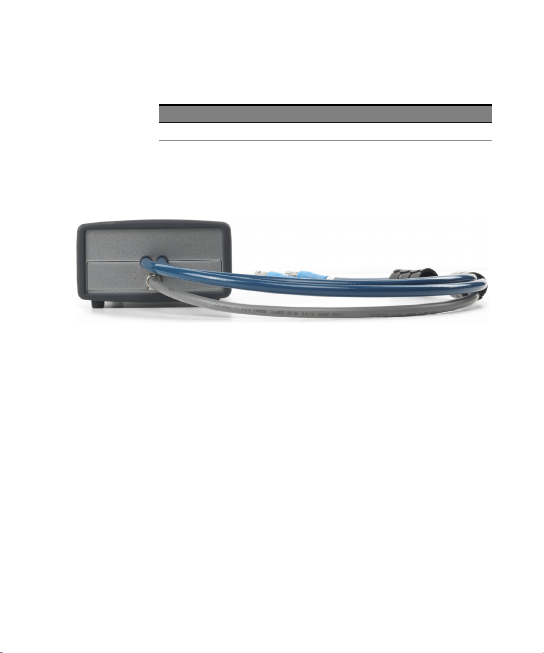
Table 10 M8057A Front Panel Inputs/Outputs Ports
Component Description
Data Out and /Data Out Connected to DUT
The following figure displays the back panel of the M8057A remote head
with its various components:
Introduction 1
Figure 8 M8057A remote head back panel
As displayed in Figure 8 on page -29, the back panel of M8057A remote
head has cables which connects with each channel of M8045A remote
head controls (P and N). The length of these cables are 85 cm.
Ensure that the chassis is NOT powered up or connected to a power
source while making connections to M8057A.
Also, make sure NOT to remove the M8057A connections when it is
powered on. However, if you wish to remove the M8057A connections,
ensure that the instrument is powered off.
Keysight M8040A High-Performance BERT Getting Started Guide 29
Page 30

Page 31

Keysight M8040A High-Performance BERT
Getting Started Guide
2 Basic Setup for
M8040A
Step 1 - Unpack the Shipment / 32
Step 2 - Set up the M8040A / 33
Step 3 - Set up the External Host Computer (not required for
M8040A-BU1)
Step 4 - Connect the M9505A AXIe Chassis to a Power Supply / 36
Step 5 - Power Up (if connecting via PCIe) / 37
Step 6 - Verify Basic M8040A Operation / 38
Step 7 - Install Keysight IO Libraries Suite (not required for M8040A-BU1)
/ 39
Step 8 - Install M8070A Software (not required for M8040A-BU1) / 39
Step 9 - Install the Licenses / 40
Step 10 - Turning off the Chassis and Modules / 52
Step 11 - Connect the M8040A to the Device Under Test (DUT) / 52
/ 33
Page 32

2 Basic Setup for M8040A
Step 1 - Unpack the Shipment
The M8040A-BU1 or M8040A-BU2 is shipped with the modules preinstalled in the M9505A AXIe Chassis.
Unpack and verify the shipment contents to check if you have received all
the items that you ordered. The shipment contents can vary depending on
the options that you ordered. Therefore, the shipping list delivered with the
shipment should supersede these lists.
Table 11 Typical contents of an M8040A instrument shipment
Item Description
M8040A-BU1 or
M8040A-BU2
Accessories The accessories will vary depending on the M8040A and the
M8070A CD-ROM with M8070A system software.
Start Here Document which provides instructions to be followed before
Tips for Preventing Damage
Guide
Getting Started Guide This document, M8040A Getting Started Guide. (Please check
The M8040A that you ordered. All modules are pre-installed in
the M9505A AXIe Chassis.
options that you ordered while purchasing the module.
Accessories include standard items that are shipped with the
M8040A as well as optional items that you ordered separately.
(Please check the M8040A product data sheet for the latest list
of default and optional accessories. Latest version can be
downloaded from www.keysight.com/find/M8040A)
operating the M8040A High-Performance BERT.
Document which provides tips for preventing damage to M8040A
High- Performance BERT.
the Keysight website:
www.keysight.com/find/M8040A for the latest guide.)
Carefully inspect all items in the shipment for any damage.
32 Keysight M8040A High-Performance BERT Getting Started Guide
Page 33

Return the Damaged/Defective Item to Keysight for Repair/Replacement
NOTE
Step 2 - Set up the M8040A
Basic Setup for M8040A 2
If anything is missing, defective, or damaged,
1 Review the warranty information shipped with your product or check
the warranty information on Keysight website.
• To check the warranty information on your module, go to
www.keysight.com/find/warranty and specify the module’s model
number (for example, M8045A) in the Product Number field, and
specify the serial number from the top of the module in the Serial
Number field.
2 Contact the nearest Keysight Sales Office. If you need assistance
finding Keysight contact information, go to
www.keysight.com/find/assist (worldwide contact information for
repair and service).
This step does not have to be performed while verifying the basic setup for
power up and connectivity. However, you will need to decide on a
benchtop or rack mounted usage of the M8040A after this basic
verification. For the procedures on how to set up the M8040A, refer to the
Installation Guide.
Step 3 - Set up the External Host Computer (not required for M8040A-BU1)
Perform this step if you are using a laptop or desktop computer as the
host computer.
The host computer communicates with the ESM and instrument modules
in the chassis and hosts all the software components needed to use the
instrument modules.
Keysight M8040A High-Performance BERT Getting Started Guide 33
Page 34

2 Basic Setup for M8040A
NOTE
NOTE
Computer Hardware and Software Requirements
The following are the hardware and software requirements that should be
met on the host computer before the installation of software components
on this computer:
Hardware requirements
• Pentium® processor 1 GHz or equivalent
• 16 GB available RAM
• USB 2.0 (Mini-B) recommended
• PCIe 2.0/8x (only for highest data throughput and desktop PC)
• VGA resolution 1024 x 768
• 1.5 GB or more free hard disc space
Software requirements
• The following operating systems are supported:
• Windows 8.1 (64 bit) SP1
• Windows 8 (64 bit)
• Windows 7 (64 bit)
• Keysight I/O libraries version 17.1
The M8070A software is required to control the M8040A. M8070A-0TP
or M8070A-0NP license is required for controlling hardware.
PCIe connectivity between the M9505A AXIe Chassis and an external
desktop PC controller is recommended when full channel plus large
patterns need to be downloaded.
34 Keysight M8040A High-Performance BERT Getting Started Guide
Page 35

To connect via USB
USB Port
PCIe Port
To connect via PCIe
Basic Setup for M8040A 2
If you are planning to use USB connectivity between the M9505A AXIe
Chassis and host computer, then you can use a laptop or desktop
computer with USB 3.0 support as the host computer.
Figure 9 USB port on the font panel of the AXIe ESM
In case of PCIe connectivity, the host computer can be a desktop PC with
an available x8 or wider PCIe slot.
Review the Keysight recommended list of host computers at
http://literature.cdn.keysight.com/litweb/pdf/5990-7632EN.pdf that are
compatible with the Keysight M9505A AXIe Chassis.
Figure 10 PCIe port on the front panel of the AXIe ESM
Keysight M8040A High-Performance BERT Getting Started Guide 35
Page 36

2 Basic Setup for M8040A
Step 4 - Connect the M9505A AXIe Chassis to a Power Supply
You can use an external power supply, typically AC power mains.
1 The instrument module uses the power supplied by the M9505A AXIe
Chassis in which it is installed. The M9505A AXIe Chassis power cord
comes with the chassis shipment. Insert the power cord into the inlet
at the rear of the chassis.
2 Connect the cord to an appropriate AC power main.
3 Push the circuit breaker to the right, which is the ON position.
Figure 11 Chassis circuit breaker
36 Keysight M8040A High-Performance BERT Getting Started Guide
Page 37

Step 5 - Power Up (if connecting via PCIe)
NOTE
Power up all the connected hardware components in the M9505A AXIe
Chassis.
1 Press the ON/Standby button on the front panel of the chassis to
power on the chassis.
Figure 12 Chassis ON/standby button
2 After powering up the chassis, wait until the Status LED of the ESM is
solid green. This ensures that the PCIe channel in the chassis is ready
for the successful connectivity of the chassis to the host computer.
3 Wait until the Access LED(s) of the module(s) in the chassis is/are solid
green.
4 Power up the host computer. By this time, the Status LED of the ESM
in the chassis and the Access LED(s) of the module(s) should have
been steady green indicating a power ready status of the setup.
Basic Setup for M8040A 2
The step to power up the host computer is not required if you are using
the M9537A AXIe Embedded Controller module as the host computer
because it gets powered on simultaneously with the chassis through
the chassis backplane.
If you plan to connect the M8040A to a corporate LAN and the M9537A
AXIe Embedded Controller is installed, you must use the Ethernet port
available on the M9537A AXIe Embedded Controller or the LAN port on
the external PC.
Keysight M8040A High-Performance BERT Getting Started Guide 37
Page 38

2 Basic Setup for M8040A
NOTE
To power down a chassis, first turn off the host computer and then power
down the chassis using the On/Standby button on its front panel.
If you are using the M9537A AXIe Embedded Controller module as the
host computer, ensure that you first shut down the controller by
executing the Windows shutdown process.
Do not use the circuit breaker for routine chassis turn off.
The module(s) are turned off automatically with the chassis.
Step 6 - Verify Basic M8040A Operation
After powering ON the connected hardware components, you can verify if
you have correctly set up the hardware if:
• a steady green status light is displayed on the ESM of the M9505A AXIe
Chassis indicating that the chassis has powered up successfully.
• the Access LED on the front panel of the instrument module turns on
indicating that the module is in a power- ready state.
• the Out of Service (OOS) LED on the front panel of the M9537A AXIe
Embedded Controller turns off. (Applicable only when you are using
M9537A AXIe Embedded Controller as the host computer).
If the chassis does not power up to a steady green Status light, or powers
up to a steady red light, the chassis has detected a failure and requires
service.
If the Fail LED on the front panel of the instrument module is steady red
and does not turn off, it indicates a power fault condition. In such a
situation, the instrument module may require repair/service.
Contact your Keysight representative to replace or service the
chassis/module.
38 Keysight M8040A High-Performance BERT Getting Started Guide
Page 39

Basic Setup for M8040A 2
NOTE
NOTE
NOTE
Step 7 - Install Keysight IO Libraries Suite (not required for M8040A-BU1)
IO Libraries Suite version 16.3 or later is required. Always use the latest
version of the Keysight IO Libraries.
Perform this step if you are setting up an M8040A-BU2 system or the
host computer you are using as part of the M8040A system requires I/O
library installation.
1 Disconnect any devices connected to the host computer.
2 If open, close all applications on the host computer.
3 Insert the Automation-Ready CD in your CD-ROM drive or download
and install the IO Libraries from www.keysight.com/find/iosuite.
4 Follow the instructions as prompted during the installation.
5 After installation, you will see the Keysight IO icon in the taskbar
notification area of the host computer screen.
Step 8 - Install M8070A Software (not required for M8040A-BU1)
Perform this step if you are setting up an M8040A-BU2 system or the
host computer you are using as part of the M8040A system requires I/O
library installation.
You will need to install the M8070A Software and license file to control the
M8040A.
A CD-ROM is shipped when ordering the M8070A (part of the M8040A
configuration).
Keysight M8040A High-Performance BERT Getting Started Guide 39
Page 40

2 Basic Setup for M8040A
NOTE
Step 9 - Install the Licenses
To install the software
1 Insert the CD ROM into the host computer or download the latest
M8070A software from www.keysight.com/find/M8040A.
2 Double-click the setup (.exe) file.
The InstallShield Wizard is displayed.
3 If displayed, click Install to continue or click Next if the system
controller meets the minimum system configuration requirements
displayed by the wizard.
4 When displayed, accept the license agreement and click Next.
5Click Install to start the installation then follow any on-screen
prompts/instructions.
6 In Windows click Start > All Programs > Keysight M8070A > Keysight
M8070A to verify software installation. The Startup screen of the
M8070A software should display.
All M8040A-BU1 licenses have been pre-installed (except for a
floating/networked license). All other system configurations require
license installation as described in this step.
The M8070A software requires a license to communicate with the M8040A
hardware. You either purchased an M8070A license to install on a
dedicated host computer (M8070A- 0TP) or one that can be installed on a
network server that will be used as a license server for operation over a
company network (M8070A-0NP, floating/networked).
In addition to the M8070A license, the M8040A, being a modular product,
includes different sets of modules hosted in an M9505A AXI chassis. Each
module has its own licenses corresponding to specific features. Module
licenses are pre-installed at the factory according to the specific options
that were ordered.
For more detailed information about licensing, refer to the M8070A User
Guide.
40 Keysight M8040A High-Performance BERT Getting Started Guide
Page 41

Installing M8070A-0TP License (not required for M8040A-BU1)
The following procedure shows how to redeem and install an M8070A
license on a dedicated host computer.
1 Locate the Software License Entitlement Certificate.
2 Follow the instructions on the Software License Entitlement
Certificate to redeem your license.
3 You will receive a license file (in an email). The file has the suffix .lic.
4 Follow the instructions in the email to complete the installation of the
license file.
5 In the M8070A software interface, verify that the license has been
installed by selecting Utilities > Licenses... then viewing the license
status in the Installed column.
Installing Temporary License (Trial License) for the M8000 Series
A temporary (trial) license differs from the perpetual license in a way that it
has an expiration date. These licenses are typically provided at no charge
for evaluation of new functionality that is licensed. Also, rental companies
may use the trial licenses to enable a certain functionality for a limited
time-frame.
A temporary (trial) license can be of the following two types:
• 30 days free trial license - The 30 days free trial license for the M8000
Series of BER Test Solutions can be downloaded using the following
weblink:
http://www.keysight.com/main/editorial.jspx?cc=IN&lc=eng&ckey=262
4767&nid=-32914.1100508&id=2624767
• 9 months DST license - The DST license can only be ordered by rental
companies and distributors.
The following procedure shows how to redeem and install a trial license on
a dedicated host computer.
1 Locate the Software License Entitlement Certificate.
2 Follow the instructions on the Software License Entitlement
Certificate to redeem your license.
3 You will receive a license file (in an email). The file has the suffix .lic.
4 Follow the instructions in the email to complete the installation of the
license file.
5 In the M8070A software interface, verify that the license has been
installed by selecting Utilities > Licenses... then viewing the license
status in the Installed column.
Basic Setup for M8040A 2
Keysight M8040A High-Performance BERT Getting Started Guide 41
Page 42
2 Basic Setup for M8040A
NOTE
Installing M8070A-0NP Floating/Networked License
An M8070A-0NP floating/networked license resides on a network server
and is accessible by multiple users. The user checks out a license each
time the software is accessed. The server tracks the number of licenses
checked out and the number of licenses available for use.
The server must be running license services. This server can be a
dedicated computer running the license server or it can run license
services and the M8070A software concurrently.
Firewall Configuration for Licensing
If your instrument or PC has a firewall installed and enabled, your system
administrator may need to allow certain executables and/or a limited
range of port numbers to go through the firewall. This topic discusses
those ports and configuration for three common firewalls.
Typically, the Licensing installer will do the necessary configuration of
the Windows firewall. These instructions are provided in case you need to
verify or modify the firewall configuration manually.
1 In Windows click Start > Control Panel > System and Security >
Windows Firewall.
2 In the left pane, click Allow a program or feature through Windows
Firewall. If this is not accessible, perform the following alternate
procedure:
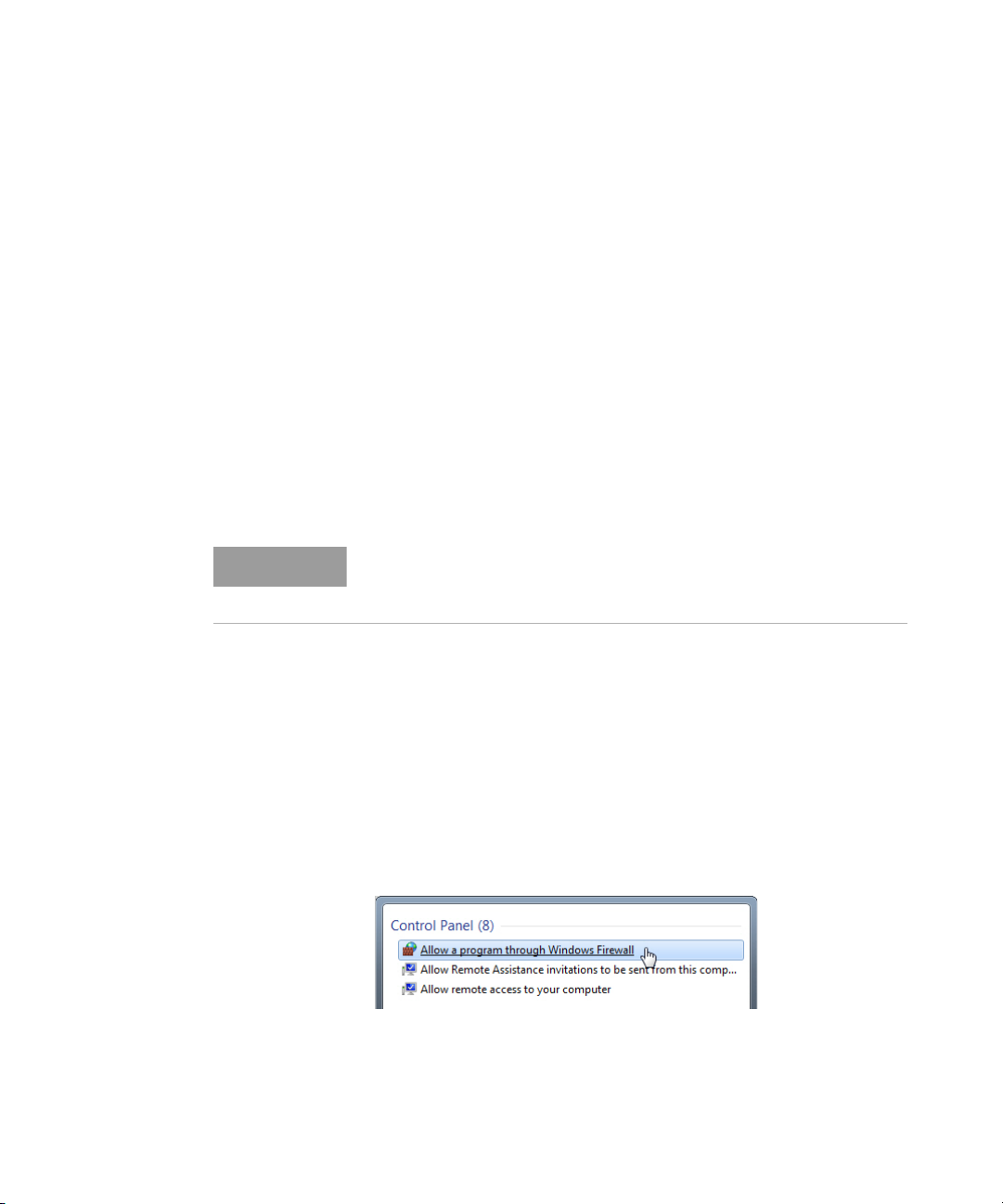
a In Windows, click the Start button and enter Allow a program
through Windows Firewall in the search field.
b In the Control Panel, select Allow a program through Windows
Firewall as shown in Figure 13 on page -42.
Figure 13 Control Panel
42 Keysight M8040A High-Performance BERT Getting Started Guide
Page 43
Basic Setup for M8040A 2
3Click Change Settings. You may need to provide an administrator
password or provide confirmation for this action.
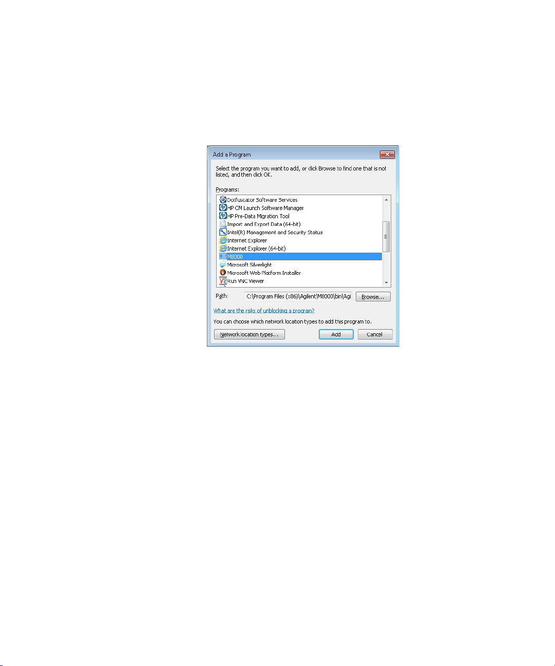
4Click on the Allow another program button.
Figure 14 Select program
5 Select M8000 then click Add.
6 Add program path:
C:\Program Files (x86)\FlexNet Publisher License Server Manager\
lmadmin.exe.
7 Repeat step 4 and step 5 to add the other programs.
8In the Allowed Programs dialog, click OK to save the settings.
Installing the FlexNet License Manager
The FlexNet License Manager tools associated with floating licenses are
available from Flexera at www.keysight.com/find/fnptools. You must use
version 11.11.1 or higher.
FlexNet provides two different license server executables: lmgrd.exe and
lmadmin.exe. You can use either one or the other.
Keysight M8040A High-Performance BERT Getting Started Guide 43
Page 44

2 Basic Setup for M8040A
Imadmin Installation
The following procedure describes how to install lmadmin.exe (server
side):
1Copy the agilent.lic file from the Keysight Licensing installation path
(typically found in, C:\Program Files\Agilent\ACCL\Licensing\bin or
C:\Program Files (x86)\Agilent\\ACCL\Licensing\bin) into the licensing
folder. (The license filename will change to agilent0.00.lic after
successful installation.)
2 Determine whether the target system has Java installed, if not, install
it from www.java.com. The Java virtual machine is required to run the
lmadmin.exe installer.
3 Run the lmadmin.exe. (Right-click the installer file and Run as
Administrator.) During the installation:
1 Accept the default installation path.
2 Check the box to Install Visual C++ 2005 SP1 Redistributable.
3 On the Service Configuration page, enter the HTTP Port Number:
‘8090’.
4 On the Service Configuration page, select the check-box to Run as
Service.
5 On the Start the Server page, select the check box to Start server
now. If you don't do it now, then you will need to start the lmadmin
service before configuring the license server.
4If the web browser does not shows the license configuration page, just
exit the browser and reboot the PC.
5 After reboot start the browser and use the use following
http://localhost:8090/ address again.Now you should see the web
configuration page of the lmadmin.
6 However, if you see the message ‘The page can’t be displayed …’ again
the firewall of windows has block the access. You may need to allow
certain executable and/or the port number to go through the firewall.
For firewall settings, refer to Firewall Configuration for Licensing on
page 42.
7 In the login page, if you have not previously set up a login, sign in as
“user admin” with password “admin”. You will then be required to
change the password.
8 Start the browser and use the use following http://localhost:8090/
address again.
9The lmadmin is installed as service. To check the state of the service,
right click on the Computer icon on the desktop and then select
Manage. Click on Services and check if service lmadmin is started.
44 Keysight M8040A High-Performance BERT Getting Started Guide
Page 45

10 Login to the lmadmin web configuration page. Add the agilent.lic and
the M8070A-0NP.
C:\Program Files (x86)\Agilent\ACCL\Licensing\bin\agilent.lic
…\1001562893_1166729.lic
11 On the client side, install the M8070A software on the client PC.
12 Install the edited license M8070A-0NP on the client (import license in
the Keysight License Manager).
13 In the Keysight License Manager, verify by opening the ‘Licenses list’
and ‘Feature Detail’ view. The following illustration displays the
‘Licenses list’ view.
14 Start the M8070A software. From the menu bar, select Utilities >
Licenses.... The M8070A license dialog will display the installed
licenses.
15 Request a floating license. For details, refer to Acquiring Floating
Licenses on page 46.
Lmgrd Installation
The following procedure describes how to install lmgrd.exe (server side).
1Copy the agilent.lic file from the license installation path
(typically found in, C:\Program Files\Agilent\ACCL\Licensing\bin or in
C:\Program Files (x86)\Agilent\ACCL\Licensing\bin into the licensing
folder. (The license file name will change to agilent0.00.lic after
successful installation).
2 Copy the appropriate version of lmgrd.exe (32-bit or 64-bit, depending
on your operating system) to the target system. It is recommended to
put lmgrd.exe in the Keysight Licensing installation path (see step 1 for
path information).
3 Install floating licenses to the licensing folder, C:\Program Files\
Agilent\Licensing.
4 Open a DOS prompt and change directory to the location of lmgrd.exe.
5 Launch lmgrd.exe with the following command:
lmgrd.exe -z -c "C:\Program Files\Agilent\licensing"
6 If the license server is running (lmgrd.exe) you will see the licenses in
the Keysight License Manager on the server.
7 On the client side, install the edited license M8070A-0NP (import
license in the Keysight License Manager)
8In the Keysight License Manager, verify by opening the ‘Licenses list’
and ‘Feature Detail’ view.
Basic Setup for M8040A 2
Keysight M8040A High-Performance BERT Getting Started Guide 45
Page 46

2 Basic Setup for M8040A
9 Start the M8070A software. From the menu bar, select Utilities >
Licenses.... The M8070A license dialog will display the installed
licenses.
10 Request a floating license. For details, refer to Acquiring Floating
Licenses on page 46.
Acquiring Floating Licenses
1 Contact your Keysight Technologies representative to purchase
licenses for your software. You will receive an order number and
certificate number, which you will use to request a license file in step 3.
2 Select and configure your license server machine as described above.
For more information, refer to the Flexera Software License
Administration Guide. You must install Keysight Licensing on the
license server computer, as described in Creating a New License
Service Using lmadmin.exe on page 47, before requesting a license file
in step 3.
3 Request a license file for your license server machine:
1 Determine the host name and serial number (10-digit alphanumeric
sequence, which is the second component of the host ID) of your
license server from Keysight License Notifier's About box.
2To display the About box, right-click the Keysight License Notifier
icon in the notification area (bottom right of your screen) and click
About Keysight License Notifier.
• You will need the highlighted items shown in the following figure:
• Visit the Keysight Software Manager website to request a license
file.
46 Keysight M8040A High-Performance BERT Getting Started Guide
Page 47

4 When you receive your license via e-mail from Keysight Technologies,
NOTE
NOTE
carefully read the instructions sent with the license. If the license is a
"served" or "floating" license, put it in the directory C:\Program Files\
Agilent\licensing on the license server.
Creating a New License Service Using lmadmin.exe
1 To access the lmadmin license server management interface, open a
Web browser and navigate to http://<server>:8080, where <server> is
the name of the computer on which the license server is running. For
this first-time configuration, you need to be logged on to the license
server computer, so you can just navigate to http://localhost:8080.
If the browser cannot find the web page, then the lmadmin service may
not be running on the server. Go to Start > Control Panel > Administrative
Tools > Services, find “lmadmin” and Start the service. After starting the
service, refresh or try navigating the browser to the Web page again.
2 Select the Administration tab.
3 Log in. If you have not previously set up a login, sign in as user "admin"
with password "admin". You will then be required to change the
password (don’t forget this password).
4 Select the Vendor Daemon Configuration tab.
5 Select Import License.
6 Browse to the new floating license file. You can only choose one file at
this step, so if you have more than one license file, then pick one of
them and click Import License.
Basic Setup for M8040A 2
To add more license files, perform the following steps.
7An Import Error and an Import Warning will be displayed indicating
that it can’t find the Agilent.exe file. Click OK.
8 Select the “Keysight” vendor daemon and click Administer.
9 Change the License File or Directory to “licenses\Agilent” instead of
the file you specified above. This will enable you to easily add more
license files.
Keysight M8040A High-Performance BERT Getting Started Guide 47
Page 48

2 Basic Setup for M8040A
NOTE
10 Change the Vendor Daemon Location (which is blank) to the location
of the Agilent.exe file:
a For 32- bit Windows, enter “C:\Program Files\Agilent\ACCL\
Licensing\bin\Agilent.exe”.
b For 64- bit Windows, enter “C:\PROGRA~2\Agilent\ACCL\
Licensing\bin\Agilent.exe”.
For 64-bit Windows, the file is in “C:\Program Files (x86)”, but the Web
page does not allow you to enter a file path containing an open or close
parenthesis, so you must instead enter the short file name
“C:\PROGRA~2” of the path.
11 Click Save.
12 Start the daemon by pressing Start.
13 To verify the status of the server, select the Dashboard tab and click
the Concurrent button. Wait for the Web page to refresh. If the
“Keysight” daemon is not selected in the vendor drop- down list in the
upper right side of the Licenses page, then select it. Click Select.
You will now see the list of floating licenses that are managed by
lmadmin.exe.
Installing and Setting up Client PC Floating Licenses
The following procedures show how to install and set up client PC floating
licenses. Repeat this procedure for each client PC.
1 Ensure that you have the Keysight Licensing Services and the M8000
software to be installed on the client PC.
2 Create the Client floating license files.
The Client floating license files redirect licensing requests to the
license server. Only one client floating license file needs to be created.
This client floating license file is copied and re- used by each client PC.
a Make a copy of the original license server floating license file.
Remove all line entries except these three lines, which you must
modified as shown.
• “SERVER” line: Keep original text
• “VENDOR” line: If the optional VENDOR line “port” number is
included in the original server license file, remove the optional
“Vendor” daemon TCP/IP port number from the line
• “USE_SERVER” line: Keep original text
48 Keysight M8040A High-Performance BERT Getting Started Guide
Page 49

Basic Setup for M8040A 2
3 Install the client floating license files.
a Start the Keysight License Manager by double clicking the Keysight
License Notifier icon or click Start > All Programs > Keysight
License Manager > Keysight License Manager.
b To install the license file, drag-and-drop the license file onto the
Keysight License Manager “License Features” window.
Alternatively, you can click the Keysight License Manager menu
File.
c Install and follow the prompts to install the license file. The license
files are stored in different folder locations depending on whether
the license Server and client reside on separate PCs or the same PC.
• License Server and Client reside on separate PCs: C:\Program
Files\Agilent\licensing
• License Server and Client reside on same PC: C:\Program Files\
Agilent\licensing\Remote Licenses
4 Verify the client PC configuration is correct.
When the license file is successful installed, The client floating licenses
that are available on the license server are listed in the Keysight
License Manager “License Products and Features” window. To view
the available licenses, select the Localhost tree, Remote Licenses
node. Ensure that your licensed options and features are shown.
Installing Module Licenses (for upgrades only)
Installing module licenses is only necessary if you add module options
onsite. Module licenses enable specific options in the modules of the
M8040A system. Once a module license has been installed using the
Keysight License Manager, the next time the M8070A software and
M8040A hardware are started, the license is recognized by the M8070A
software and compared to the module’s serial number. If the PC Host ID
and serial number match, the EEPROM in the module is programmed and
the option is enabled. Even if the M8070A software license is transported
to another host computer, the module option will remain enabled.
The following procedure shows how to redeem and install a module
license.
1 Locate the Software License Entitlement Certificate (email or paper
copy).
2 Follow the instructions on the Software License Entitlement Certificate
to redeem your license.
3 You will receive a license file (in an email). The file has the suffix .lic.
Keysight M8040A High-Performance BERT Getting Started Guide 49
Page 50

2 Basic Setup for M8040A
Transporting an M8070A License
4 Follow the instructions in the email to complete the installation of the
license file.
5 In the M8070A software interface, verify that the license has been
installed by selecting Utilities > Licenses then viewing the license
status in the Installed column.
Transportable licenses are licenses that can be moved from one host
controller to another using the Keysight License Manager. For detailed
information about transportable licenses, refer to the M8070A User Guide.
If you need to download and install the Keysight License Manager, go to
the following Web page: http://www.keysight.com/find/LicenseManager
1 Start the Keysight License Manager by double clicking the Keysight
License Notifier icon or click Start > All Programs > Keysight License
Manager > Keysight License Manager.
2In the Keysight License Manager, click on Help > Keysight License
Manager Help and perform the procedure in the Transporting
Licenses help topic.
50 Keysight M8040A High-Performance BERT Getting Started Guide
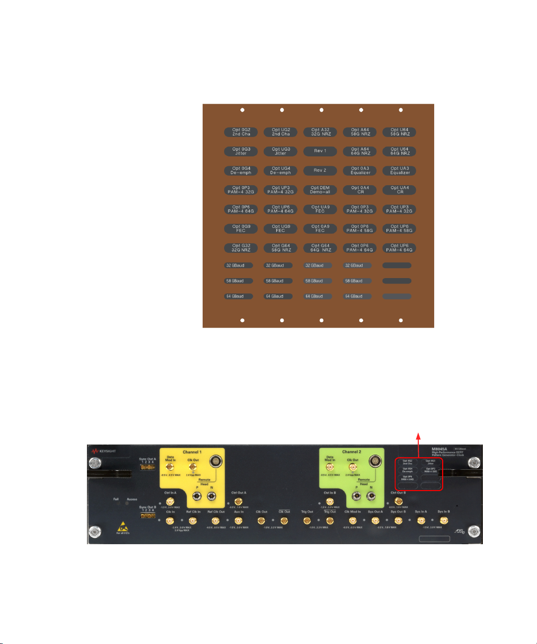
Affix Option Label (optional)
Whenever the M8040A is upgraded with additional options, it is
recommended that you affix the corresponding label(s) to the front panel
of the module. The option labels provide a quick view of which options are
installed in each module. Figure 15 on page -51 shows the option label
sheet provided with your M8040A system.
Page 51
Basic Setup for M8040A 2
Option Labels
Figure 15 Option label sheet
1 Locate the option label sheet shown in Figure 15 on page -51.
2 Affix the option labels as shown in Figure 16 on page -51.
Figure 16 Affix option labels
Keysight M8040A High-Performance BERT Getting Started Guide 51
Page 52

2 Basic Setup for M8040A
NOTE
USB
DUT
Loopback to ED
External Bandpass Filter
Step 10 - Turning off the Chassis and Modules
Turn off the chassis and module in the following sequence:
1 Turn off the host computer. If you are using the Keysight AXIe
Embedded Controller module as the host computer, ensure that you
shut down the controller by executing the Windows shutdown process.
2 Turn off the chassis by pressing the chassis ON/STANDBY switch on
the front panel of chassis. Do not use the circuit breaker for routine
turn off. The module(s) are turned off automatically with the chassis.
Step 11 - Connect the M8040A to the Device Under Test (DUT)
This section describes how you can connect the M8040A to a DUT.
If you are connecting M8040A over USB, make sure to disable the “Sleep
Mode” of the external PC or laptop. Failing to do so may cause you to
re-initialize the M8070A software.
52 Keysight M8040A High-Performance BERT Getting Started Guide
Typical Test Setup Example
Figure 17 on page -52 is an example of a common test setup for testing a
DUT.
Figure 17 Typical test setup example
Page 53

NOTE
In the CLK/2 mode, for symbol rates above 25 GBaud, an external
Loopback to ED
DUT
External Bandpass Filter
NOTE
bandpass filter has to be used on the clock input of M8046A. The filter
has to be removed for symbol rates below 25 GBaud. However, in the
CLK/1 mode, no external bandpass filter is required.
M9537A Embedded Controller Setup Example
Figure 18 on page -53 shows a basic setup using the M9537A Embedded
Controller. The embedded controller module must be installed in slot 1 of
the M9505A AXIe Chassis. The embedded controller module
communicates with the ESM through the chassis backplane. Therefore,
there is no need to establish any external PCIe/USB or LAN connection
between the embedded controller module and chassis.
Basic Setup for M8040A 2
Figure 18 M9537A embedded controller setup example
In the CLK/2 mode, for symbol rates above 25 GBaud, an external
bandpass filter has to be used on the clock input of M8046A. The filter
has to be removed for symbol rates below 25 GBaud. However, in the
CLK/1 mode, no external bandpass filter is required.
Keysight M8040A High-Performance BERT Getting Started Guide 53
Page 54

2 Basic Setup for M8040A
Hardware Connections
Make the hardware connections as described below:
• Connect the M8057A to M8045A channel 1 remote head control.
• Connect the M8057A to M8045A channel 1 remote head controls
(P and N).
• Ensure that the chassis is NOT powered up or connected to a power
source while making connections to M8057A.
• Terminate unused ports (TRG Out, Data Out and Clk Out) with 50 Ohm
to GND.
54 Keysight M8040A High-Performance BERT Getting Started Guide
Page 55

Keysight M8040A High-Performance BERT
Getting Started Guide
3 Using the M8040A
High-Performance
BERT
Locating Electronic Manuals and Online Help / 56
Routine Care / 56
Starting the M8070A Software / 57
Perform a Measurement / 58
Updating Software Components / 66
Contacting Keysight Service and Support / 66
Quick Troubleshooting / 66
Page 56

3 Using the M8040A High-Performance BERT
NOTE
CAUTION
CAUTION
Locating Electronic Manuals and Online Help
Various electronic manuals and the M8070A Online Help provide
information on how to configure and use the supported instrument
modules.
On installing the M8070A software, you will find documentation by clicking
Start > All Programs > Keysight M8070A > Keysight M8070A
Documentation.
You can also visit www.keysight.com/find/m8040a to find the latest
versions of various manuals and the data sheet for each M8040A module.
Routine Care
Except for performing initial chassis verification or troubleshooting, do
not operate the chassis with empty slots. Always insert a filler panel in
empty slots. This is especially important for the slots on either side of an
installed instrument module. This allows proper air flow and cooling, and
provides EMI shielding for the chassis and installed components. Leaving
slots empty can increase fan speed, raise ambient noise, overheat
components, and can cause the module to shut down.
56 Keysight M8040A High-Performance BERT Getting Started Guide
Do not block the vent holes on the chassis. This overheats and damages
their components. Leave a gap of at least 2” (50 mm) around all vent
holes.
Some instruments, such as M8057A, have an internal fan to keep the
components cooled to normal operating temperatures. Make sure that
there is enough clearance for adequate air-flow.
Page 57

Starting the M8070A Software
CAUTION
NOTE
Using the M8040A High-Performance BERT 3
The enclosure surface of the module may become hot during use. If you
need to remove the module, first power down the AXIe chassis, allow the
module to cool, and then pull the module out of the chassis.
For preventing damage, for usage tips, and for ESD information, read
and follow the instructions in the “Tips for Preventing Damage Guide”
(Document Part No. #M8000-91010).
1 Ensure that the system is powered up and ready to start as described
in the sections Basic Setup for M8040A on page 31.
2 On the host computer, click on Start > All Programs > Keysight
M8070A > Keysight M8070A.
3 When the Load Settings screen appears as shown in Figure 19 on
page -57, load the last used, factor preset, or new settings.
Keysight M8040A High-Performance BERT Getting Started Guide 57
Figure 19 Load Settings screen
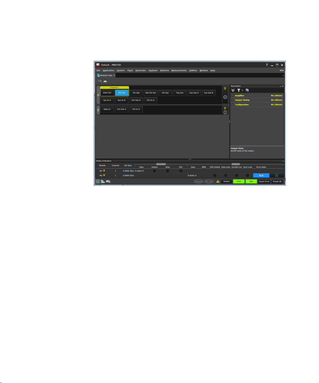
4The screen shown in Figure 20 on page -58 should now be displayed.
Page 58
3 Using the M8040A High-Performance BERT
Figure 20 M8070A user interface
Perform a Measurement
The following measurement example verifies a BER of 0 in channel 1 of the
M8045A, M8046A and M8057A.
1 Connect M8045A CLK OUT of Channel 1 to M8046A CLK IN.
2 Connect DATA OUT of Remote-Head M8057A, which is connected to
Channel 1 of M8045A, to the DATA IN of M8046A.
3 In the M8070A software interface, set the data rate to 10 Gb/s as
follows:
a Click on System > System View.
b Click on the PLL Synthesizer Internal block as shown in Figure 21
on page -59 to display the Synthesizer properties.
58 Keysight M8040A High-Performance BERT Getting Started Guide
Page 59
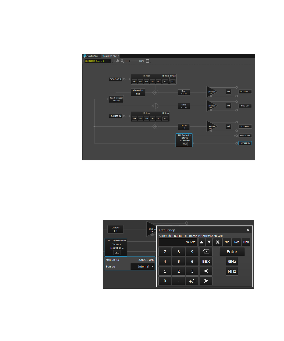
Figure 21 Synthesizer parameters
Using the M8040A High-Performance BERT 3
c In the Synthesizer parameters, click in the numeric field
corresponding to the Frequency setting.
d Using the numeric keypad, enter 10 then click on the GHz button as
shown in Figure 22 on page -59. If your system has a maximum data
rate of 8 Gb/s, leave the frequency setting at 5 GHz.
Figure 22 Set frequency to 10 GHz
Keysight M8040A High-Performance BERT Getting Started Guide 59
Page 60

3 Using the M8040A High-Performance BERT
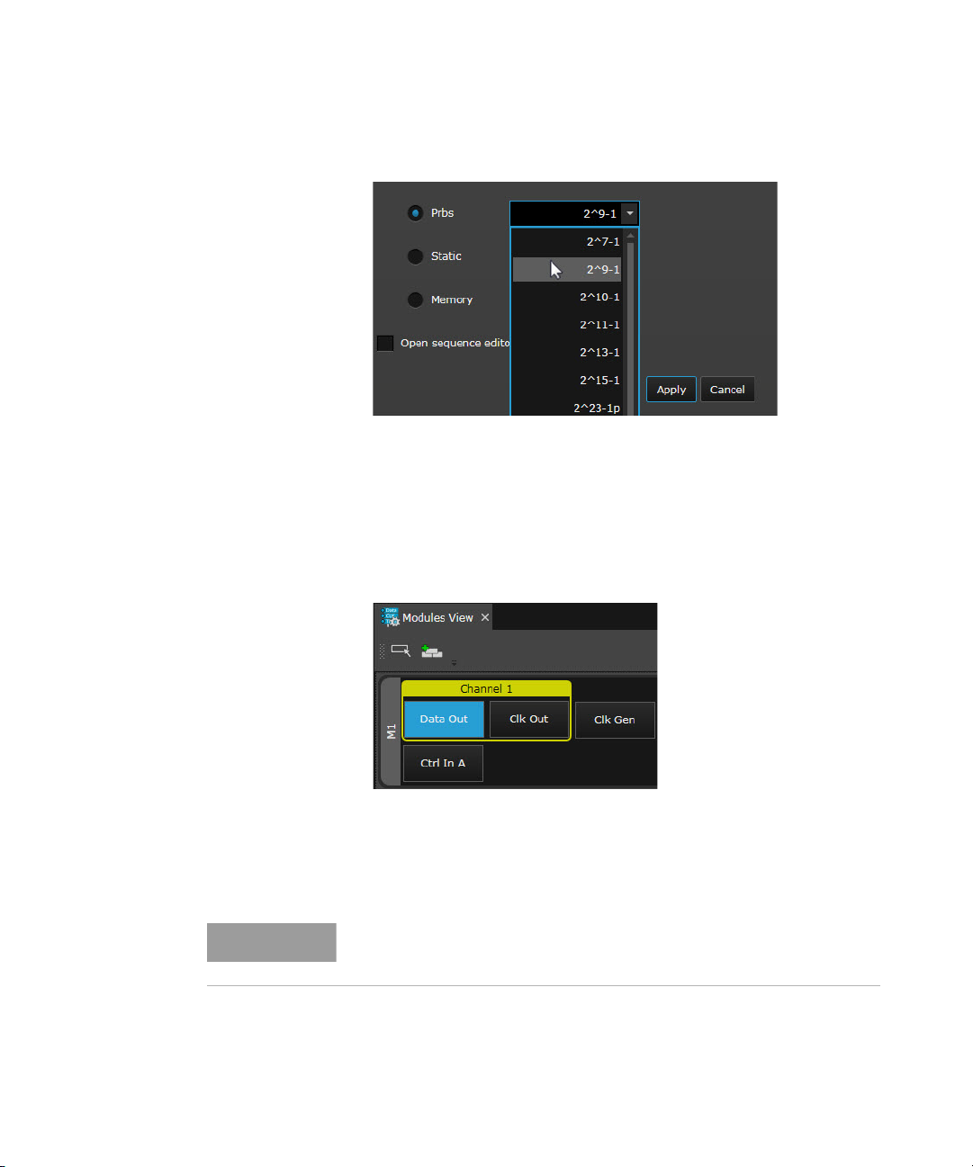
4 On the menu bar, click on Patterns > Select Pattern.... A Select
Sequence Pattern dialog will appear as shown in Figure 23 on
page -60.
Figure 23 Select Sequence Pattern Dialog
5In the Select Sequence Pattern dialog, select Prbs as the Pattern
Type and then select 2^9- 1 as the Polynomial as shown in Figure 24
on page -61.
60 Keysight M8040A High-Performance BERT Getting Started Guide
Page 61
Using the M8040A High-Performance BERT 3
NOTE
Figure 24 Select PRBS and Polynomial
6 Once done, click on Apply button.
7 Now, click on the Modules View tab.
8Click on Channel 1 > Data Out corresponding to the M8045A (M1) as
shown in Figure 25 on page -61.
Figure 25 Select Channel 1 DataOut
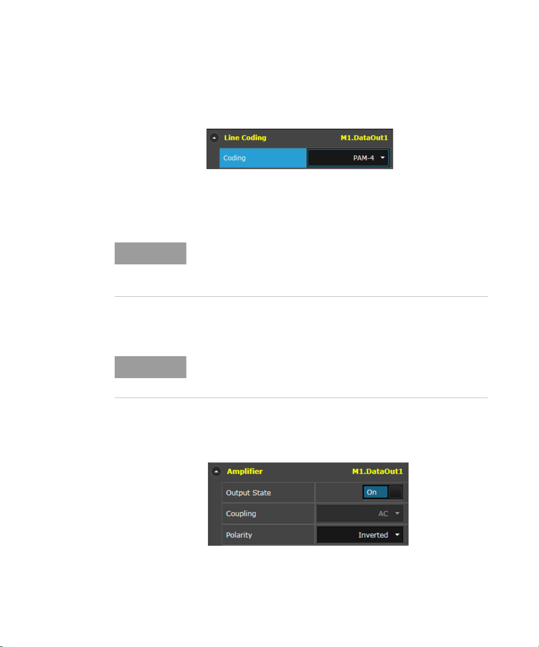
9 On the Properties Window, expand Amplifier.
10 Select the coupling type as AC Coupling.
You must select ‘AC Coupling’ when doing a loopback to the M8046A
error detector.
Keysight M8040A High-Performance BERT Getting Started Guide 61
Page 62
3 Using the M8040A High-Performance BERT
NOTE
NOTE
11 Click on Data Out corresponding to the M8045A (M1) and select the
Fi
12 Click on Clk Gen corresponding to the M8045A (M1) and set the
In the CLK/2 mode, for symbol rates above 25 GBaud, an external
bandpass filter has to be used on the clock input of M8046A. The filter
has to be removed for symbol rates below 25 GBaud. However, in the
CLK/1 mode, no external bandpass filter is required.
13 Click on Data In corresponding to the M8046A (M2) and select the line
line coding PAM-4.
gure 26 Select line coding
requency as 10 GHz.
f
coding PAM-4.
When the line cod ing “PAM-4” is selected for the loopback mode, it is
recommended to adjust the pattern generator data output de-emphasis
for the post cursor for error free operation (e.g. +0.05 at 25 Gbaud).
14 Enable the output of the pattern generator by clicking on the Output
State button as shown in Figure 27 on page -62.
Figure 27 Enable pattern generator output
62 Keysight M8040A High-Performance BERT Getting Started Guide
Page 63
Using the M8040A High-Performance BERT 3
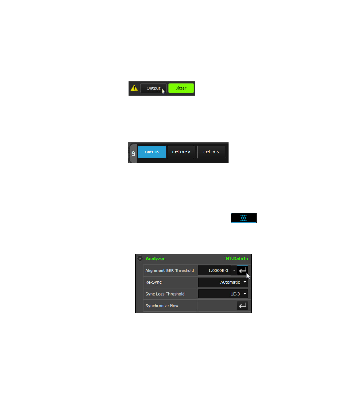
15 Enable the global outputs by clicking on the Output button present on
the Status Bar as shown in Figure 28 on page -63.
Figure 28 Enable global outputs
16 Click on Data In corresponding to the M8046A(M2) as shown in Figure
29 on page -63.
Figure 29 Select M8046A DataIn
17 On the Properties Window, expand Analyzer.
18 Click on the Alignment BER Threshold button to synchronize and align
the error analyzer as shown in Figure 30 on page -63.
Alternatively, you can also click on the Start BER
Threshold Auto Alignment button present on the Status Indicator to
synchronize and align the error analyzer.
Figure 30 Alignment BER Threshold
19 At any time you can click on the Hide Status Indicators Window icon
(bottom-left of display) to view/hide the module status including BER.
Keysight M8040A High-Performance BERT Getting Started Guide 63
Page 64

3 Using the M8040A High-Performance BERT
20 From the menu bar, click on Measurements > Error Ratio.
21 The default acquisition parameter settings are used as shown in Figure
31 on page -64.
Figure 31 Acquisition parameter settings
22 Click on the Start Measurement button to start the measurement as
shown in Figure 32 on page -64.
Figure 32 Start measurement
64 Keysight M8040A High-Performance BERT Getting Started Guide
Page 65
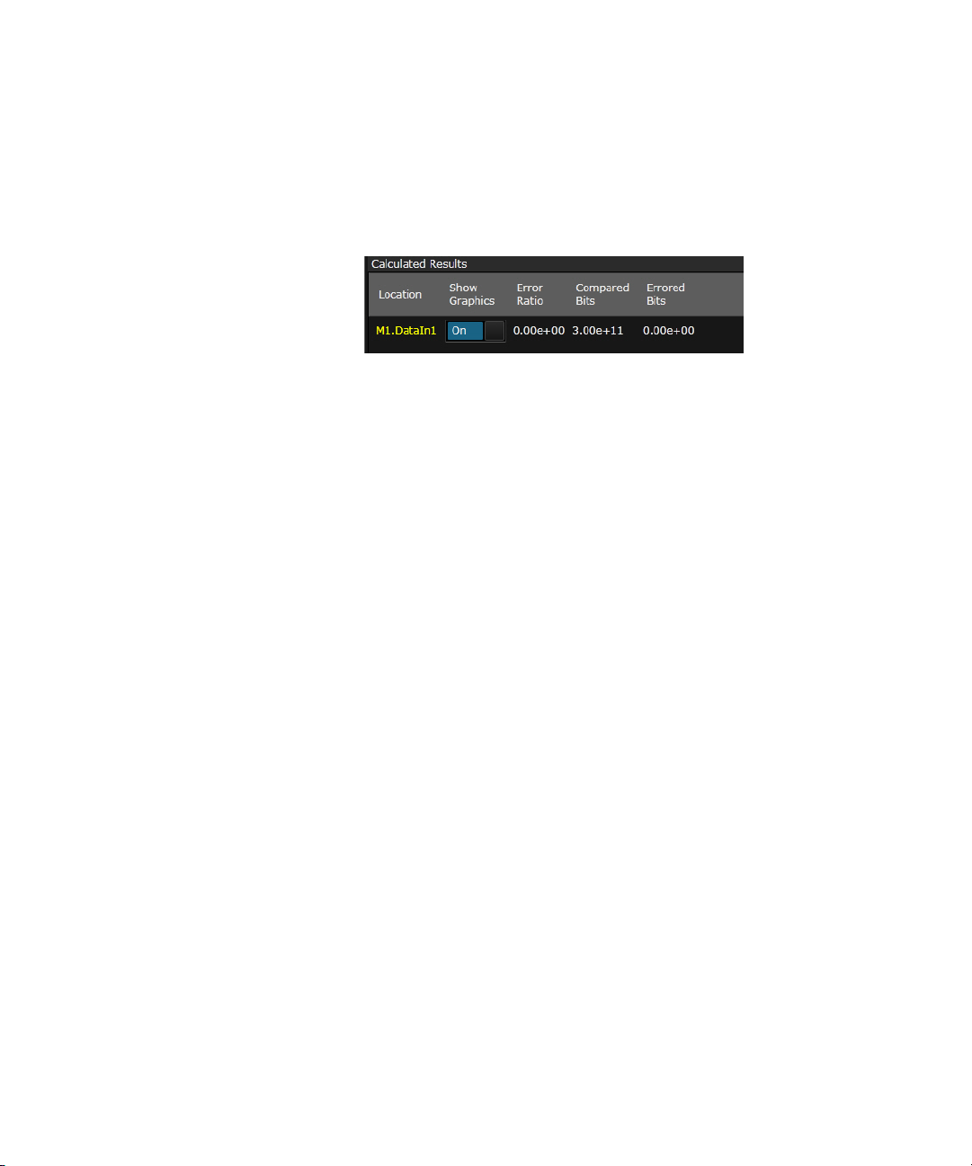
Using the M8040A High-Performance BERT 3
23 After the measurement has completed (60 sec), review the results
shown below the graph in the Calculated Results table as shown in
Figure 33 on page -65.
Figure 33 Calculated results
Keysight M8040A High-Performance BERT Getting Started Guide 65
Page 66

3 Using the M8040A High-Performance BERT
Updating Software Components
Updated versions of the M8070A and module specific software
components are available on the Keysight website.
These software components are available as .EXE files. To download a
software upgrade:
1Go to http://www.keysight.com/find/m8070a
2Click the Technical Support tab.
3Click Drivers and Software.
4 Type the model number of the instrument module for which software
update is needed and click Find. Model number is located on the front
panel of the module.
5Click the Driver and Software link on the module page.
6 Download the required software update from the list of available
updates.
Contacting Keysight Service and Support
To locate a sales or a service office near you, go to
www.keysight.com/find/contactus
Quick Troubleshooting
This section lists the basic troubleshooting steps that you might find useful
while setting up the M8040A.
The chassis does not power up
f the chassis or a module does not appear to power up, check the
following:
• The circuit breakers at the rear of the chassis are set to the right, which
is the ON position.
• The AC power cords are connected to a working power source.
• The electrical circuits are not overloaded. Check the combined power
requirements of all equipment on the same circuit.
• There are no empty slots in the chassis. Leaving slots empty can
overheat the inserted modules, causing them to shut down.
66 Keysight M8040A High-Performance BERT Getting Started Guide
Page 67

Using the M8040A High-Performance BERT 3
A module is exceptionally hot
• Check that the vent holes on the chassis are not blocked.
• Check that a filler panel module or an instrument module is installed
into empty slots on either side of an instrument module.
The host computer is not getting connected to the chassis via PCIe
• Install the instrument module in the chassis before trying to connect
the host computer to the chassis via PCIe. In the absence of an
installed module, an attached host computer will not be able to
connect to the chassis successfully.
• While powering up or restarting the host computer, make sure that you
first power up the chassis, wait until the LED turns solid green, and then
power up the host computer. This sequence is needed for the PCIe
channel in the chassis to be ready for successful PCIe connectivity
between the host and chassis.
• Windows may have failed to load the NIC drivers. This results in the
display of the NIC driver install dialog. If this situation occurs, exit the
NIC driver install dialog and install the NIC driver manually to achieve
PCIe connectivity between the chassis and host computer.
The Keysight AXIe Embedded Controller module performs poorly and
the operating system seems sluggish
This can happen if there are multiple hosts trying to communicate with the
chassis at once. In such a situation, the module’s embedded operating
system is affected by a low- level driver resource conflict.
To resolve this, ensure that there are no external remote host computers
still connected to the chassis and running.
Keysight M8040A High-Performance BERT Getting Started Guide 67
Page 68

Page 69

Index
Numerics
5-slot AXIe chassis, 17
A
AXIe chassis, 17
B
BER measurement example, 58
C
CEI-56G standards, 14
circuit breaker, M9505A, 36
D
Data In, 27, 29
DUT setup, 52
E
Embedded Controller Module, 19
Embedded System Module, 18
H
host computer types, 20
host computer, hardware/software
requirements, 34
host computer, set up external, 33
I
insertion/extraction handles, 22
IO Libraries, install, 39
L
labels, option, 50
LAN connection, 19
LEDs
Access, 22, 26
Aux In, 22
Clk In, 22
Clk Out, 22
Ctrl In A, 22
Ctrl In B, 22
Ctrl Out A, 22
Data In, 22, 26
Data Mod In, 26
Data Out, 22, 26
Delay Mod In, 23
Fail, 22, 26
Ref Clk In, 22
Ref Clk Out, 22
Sys Ctrl In A, 23
Sys Ctrl In B, 23
Sys Out A, 23
Sys Out B, 23
Trig Out, 22
license, install M8070A-0TP, 41
M
M8040A, 16
M8040A High-performance
BERT, 13
M8045A, 16
M8045A Module Components, 21
M8045A, M8046A and M8057A
configuration, 16
M8046A, 16
M8046A Module Components, 25
M8051A components, 25, 28
M8057A, 16
M8057A Remote Head
Components, 28
M8070A license transport, 50
M8070A Software, 57
M8070A Software, install, 40
M8070A Software, starting, 57
M8070A-0NP license, 42
M8070A-0TP license, 41
M9505-00230, 18
M9505A, 17
M9505A, power down, 52
M9505A, power up, 36
M9537A, 19
M9537A AXIe Embedded
Controller, 16, 19
measurement example, BER, 58
Module Insertion/Extraction
Handles, 26
module licenses, install, 49
N
NRZ, 14
O
operation, verify, 38
option labels, 50
P
PAM-4, 14
PCIe connectivity, 17, 35
PCIe, power up process, 37
R
retaining screws, 22, 26
Keysight M8040A High-Performance BERT Getting Started Guide 69
Page 70

Index
S
safety summary, 3
Sync In, 27
T
transport M8070A license, 50
U
USB connectivity, 17, 35
70 Keysight M8040A High-Performance BERT Getting Started Guide
Page 71

Page 72

This information is subject to
change without notice.
© Keysight Technologies 2017
Edition 4.0, June 2017
Printed in Germany
www.keysight.com
 Loading...