

Page 1

User Guide
Keysight L4490A/L4491A
RF Switch Platform
Page 2

Notices
© Keysight Technologies, Inc. 2015
No part of this manual may be reproduced in any form or by any means
(including electronic storage and retrieval
or translation into a foreign language)
without prior agreement and written consent from Keysight Technologies, Inc. as
governed by United States and international copyright laws.
Manual Part Number
L4490-90001
Edition
Sixth Edition, September 2015
Printed in
Malaysia
Published by
Keysight Technologies, Inc.
900 S. Taft Ave.
Loveland, CO 80537 USA
Trademarks
PICMG®, Compact PCI® are registered
trademarks of the PCI Industrial Computer Manufacturers Group.
AdvancedTCA
trademarks of the PCI Industrial Computer Manufacturers Group.
PCI-SIG®, PCI Express®, and PCIe
registered trademarks of PCI-SIG.
®
and ATCA are registered
®
are
Technology Licenses
The hardware and/or software described
in this document are furnished under a
license and may be used or copied only in
accordance with the terms of such
license.
Declaration of Conformity
Declarations of Conformity for this product and for other Keysight products may
be downloaded from the Web. Go to
http://keysight.com/go/conformity.
You can then search by product number
to find the latest Declaration of Conformity.
U.S. Government Rights
The Software is “commercial computer
software,” as defined by Federal Acquisition Regulation (“FAR”) 2.101. Pursuant
to FAR 12.212 and 27.405-3 and Department of Defense FAR Supplement
(“DFARS”) 227.7202, the U.S. government acquires commercial computer
software under the same terms by which
the software is customarily provided to
the public. Accordingly, Keysight provides the Software to U.S. government
customers under its standard commercial
license, which is embodied in its End
User License Agreement (EULA), a copy
of which can be found at http://
www.keysight.com/find/sweula. The
license set forth in the EULA represents
the exclusive authority by which the U.S.
government may use, modify, distribute,
or disclose the Software. The EULA and
the license set forth therein, does not
require or permit, among other things,
that Keysight: (1) Furnish technical information related to commercial computer
software or commercial computer software documentation that is not customarily provided to the public; or (2)
Relinquish to, or otherwise provide, the
government rights in excess of these
rights customarily provided to the public
to use, modify, reproduce, release, perform, display, or disclose commercial
computer software or commercial computer software documentation. No additional government requirements beyond
those set forth in the EULA shall apply,
except to the extent that those terms,
rights, or licenses are explicitly required
from all providers of commercial computer software pursuant to the FAR and
the DFARS and are set forth specifically
in writing elsewhere in the EULA. Keysight shall be under no obligation to
update, revise or otherwise modify the
Software. With respect to any technical
data as defined by FAR 2.101, pursuant
to FAR 12.211 and 27.404.2 and DFARS
227.7102, the U.S. government acquires
no greater than Limited Rights as defined
in FAR 27.401 or DFAR 227.7103-5 (c), as
applicable in any technical data.
Warranty
THE MATERIAL CONTAINED IN THIS
DOCUMENT IS PROVIDED “AS IS,” AND
IS SUBJECT TO BEING CHANGED,
WITHOUT NOTICE, IN FUTURE EDITIONS. FURTHER, TO THE MAXIMUM
EXTENT PERMITTED BY APPLICABLE
LAW, KEYSIGHT DISCLAIMS ALL WARRANTIES, EITHER EXPRESS OR IMPLIED,
WITH REGARD TO THIS MANUAL AND
ANY INFORMATION CONTAINED
HEREIN, INCLUDING BUT NOT LIMITED
TO THE IMPLIED WARRANTIES OF MERCHANTABILITY AND FITNESS FOR A
PARTICULAR PURPOSE. KEYSIGHT
SHALL NOT BE LIABLE FOR ERRORS OR
FOR INCIDENTAL OR CONSEQUENTIAL
DAMAGES IN CONNECTION WITH THE
FURNISHING, USE, OR PERFORMANCE
OF THIS DOCUMENT OR OF ANY INFORMATION CONTAINED HEREIN. SHOULD
KEYSIGHT AND THE USER HAVE A SEPARATE WRITTEN AGREEMENT WITH
WARRANTY TERMS COVERING THE
MATERIAL IN THIS DOCUMENT THAT
CONFLICT WITH THESE TERMS, THE
WARRANTY TERMS IN THE SEPARATE
AGREEMENT SHALL CONTROL.
Keysight Technologies does not warrant
third-party system-level (combination of
chassis, controllers, modules, etc.) performance, safety, or regulatory compliance unless specifically stated.
Safety Information
A CAUTION denotes a hazard. It calls
attention to an operating procedure
or practice that, if not correctly performed or adhered to, could result in
damage to the product or loss of
important data. Do not proceed
beyond a CAUTION notice until the
indicated conditions are fully understood and met.
A WARNING denotes a hazard. It
calls attention to an operating procedure or practice, that, if not correctly performed or adhered to,
could result in personal injury or
death. Do not proceed beyond a
WARNING notice until the indicated
conditions are fully understood and
met.
ii
Page 3

Page 4

Safety Information
The following general safety precautions must be observed during all
phases of operation of this instrument.
Failure to comply with these precautions or with specific warnings or operating instructions in the product
manuals violates safety standards of
design, manufacture, and intended use
of the instrument. Keysight Technologies assumes no liability for the customer's failure to comply with these
requirements.
General
Do not use this product in any manner not
specified by the manufacturer. The protective features of this product must not be
impaired if it is used in a manner specified in
the operation instructions.
Before Applying Power
Verify that all safety precautions are taken.
Make all connections to the unit before
applying power. Note the external markings
described under “Safety Symbols”.
Ground the Instrument
Keysight chassis’ are provided with a
grounding-type power plug. The
instrument chassis and cover must be
connected to an electrical ground to
minimize shock hazard. The ground pin
must be firmly connected to an electrical ground (safety ground) terminal at
the power outlet. Any interruption of
the protective (grounding) conductor
or disconnection of the protective
earth terminal will cause a potential
shock hazard that could result in personal injury.
Do Not Operate in an Explosive
Atmosphere
Do not operate the module/chassis in
the presence of flammable gases or
fumes.
Do Not Operate Near Flammable
Liquids
Do not operate the module/chassis in
the presence of flammable liquids or
near containers of such liquids.
Cleaning
Clean the outside of the Keysight module/chassis with a soft, lint-free,
slightly dampened cloth. Do not use
detergent or chemical solvents.
Do Not Remove Instrument Cover
Only qualified, service-trained personnel who are aware of the hazards
involved should remove instrument
covers. Always disconnect the power
cable and any external circuits before
removing the instrument cover.
Keep away from live circuits
Operating personnel must not remove
equipment covers or shields. Procedures involving the removal of covers
and shields are for use by servicetrained personnel only. Under certain
conditions, dangerous voltages may
exist even with the equipment
switched off. To avoid dangerous electrical shock, DO NOT perform procedures involving cover or shield removal
unless you are qualified to do so.
DO NOT operate damaged
equipment
Whenever it is possible that the safety
protection features built into this product have been impaired, either through
physical damage, excessive moisture,
or any other reason, REMOVE POWER
and do not use the product until safe
operation can be verified by servicetrained personnel. If necessary, return
the product to an Keysight Technologies Sales and Service Office for service and repair to ensure the safety
features are maintained.
DO NOT block the primary
disconnect
The primary disconnect device is the
appliance connector/power cord when
a chassis used by itself, but when
installed into a rack or system the disconnect may be impaired and must be
considered part of the installation.
Do Not Modify the Instrument
Do not install substitute parts or perform any unauthorized modification to
the product. Return the product to an
Keysight Sales and Service Office to
ensure that safety features are maintained.
In Case of Damage
Instruments that appear damaged or
defective should be made inoperative
and secured against unintended operation until they can be repaired by
qualified service personnel
Do NOT block vents and fan exhaust:
To ensure adequate cooling and ventilation, leave a gap of at least 50mm
(2") around vent holes on both sides of
the chassis.
Do NOT operate with empty slots: To
ensure proper cooling and avoid damaging equipment, fill each empty slot
with an AXIe filler panel module.
Do NOT stack free-standing chassis:
Stacked chassis should be rackmounted.
All modules are grounded through the
chassis: During installation, tighten
each module's retaining screws to
secure the module to the chassis and
to make the ground connection.
Operator is responsible to maintain
safe operating conditions. To ensure
safe operating conditions, modules
should not be operated beyond the
full temperature range specified in the
Environmental and physical specification. Exceeding safe operating conditions can result in shorter lifespan,
improper module performance and
user safety issues. When the modules
are in use and operation within the
specified full temperature range is not
maintained, module surface temperatures may exceed safe handling conditions which can cause discomfort or
burns if touched. In the event of a
module exceed ing the full temperature range, always allow the module
to cool before touching or removing
modules from the chassis.
iv
Page 5

Safety Symbols
A CAUTION denotes a hazard. It
calls attention to an operating
procedure or practice, that, if not
correctly performed or adhered to
could result in damage to the
product or loss of important data.
Do not proceed beyond a CAUTION notice until the indicated
conditions are fully understood
and met.
A WARNING denotes a hazard. It
calls attention to an operating
procedure or practice, that, if not
correctly performed or adhered to,
could result in personal injury or
death. Do not proceed beyond a
WARNING notice until the indicated conditions are fully understood and met.
Products display the following symbols:
Warning, risk of electric
shock
Refer to manual for additional safety information.
Earth Ground.
Chassis Ground.
Alternating Current (AC).
Standby Power. Unit is not
completely disconnected
from AC mains when
switch is in standby.
Antistatic precautions
should be taken.
The CSA mark is a registered trademark of the Canadian Standards Association and indicates compliance to
the standards laid out by them. Refer
to the product Declaration of Conformity for details.
Notice for European Community: This
product complies with the relevant
European legal Directives: EMC Directive (2004/108/EC) and Low Voltage
Directive (2006/95/EC).
The Regulatory Compliance Mark
(RCM) mark is a registered trademark.
This signifies compliance with the Australia EMC Framework regulations
under the terms of the Radio Communication Act of 1992.
ICES/NMB-001 indicates that this ISM
device complies with the Canadian
ICES-001.
This symbol represents the time period
during which no hazardous or toxic
substance elements are expected to
leak or deteriorate during normal use.
Forty years is the expected useful life
of this product.
South Korean Class A EMC Declaration. this equipment is Class A suitable
for professional use and is for use in
electromagnetic environments outside
of the home.
Waste Electrical and
Electronic
Equipment (WEEE)
Directive
2002/96/EC
This product complies with the WEEE
Directive (2002/96/EC) marking
requirement. The affixed product label
(see below) indicates that you must not
discard this electrical/electronic product in domestic household waste.
Product Category: With reference to
the equipment types in the WEEE
directive Annex 1, this product is classified as a “Monitoring and Control
instrumentation” product.
Do not dispose in domestic household
waste.
To return unwanted products, contact
your local Keysight office for more
information.
CAT I
CAT II
CAT III
CAT IV
For localized Safety Warnings, Refer
to Keysight Safety document (p/n
9320-6792).
IEC Measurement Category I, II, III, or IV
v
Page 6

vi
Page 7

1 About the Instrument
L4490A/L4491A Use Model . . . . . . . . . . . . . . . . . . . . . . . . . . . . . . . . . . . . . . . 12
Equipment Inventory . . . . . . . . . . . . . . . . . . . . . . . . . . . . . . . . . . . . . . . . . . . . . 13
Materials Included . . . . . . . . . . . . . . . . . . . . . . . . . . . . . . . . . . . . . . . . . . . . 13
Input Power and Operating Environment . . . . . . . . . . . . . . . . . . . . . . . . . . . . . 13
Recommended Accessories . . . . . . . . . . . . . . . . . . . . . . . . . . . . . . . . . . . . . . . 14
Installing Switches/Attenuators in the RF Switch Platform . . . . . . . . . . . . . . . 17
Removing the RF Platform Covers . . . . . . . . . . . . . . . . . . . . . . . . . . . . . . . . 17
Bracket-Switch Assembly . . . . . . . . . . . . . . . . . . . . . . . . . . . . . . . . . . . . . . 19
Y1170A and Y1171A Brackets. . . . . . . . . . . . . . . . . . . . . . . . . . . . . . . . . 19
Y1172 Bracket . . . . . . . . . . . . . . . . . . . . . . . . . . . . . . . . . . . . . . . . . . . . . 21
Y1173 Bracket . . . . . . . . . . . . . . . . . . . . . . . . . . . . . . . . . . . . . . . . . . . . . 22
Y1174 Bracket . . . . . . . . . . . . . . . . . . . . . . . . . . . . . . . . . . . . . . . . . . . . . 23
Y1175 Bracket . . . . . . . . . . . . . . . . . . . . . . . . . . . . . . . . . . . . . . . . . . . . . 24
L4490A/L4491A Switch Trays and Options . . . . . . . . . . . . . . . . . . . . . . . . . 25
L4490A Switch Tray. . . . . . . . . . . . . . . . . . . . . . . . . . . . . . . . . . . . . . . . . 25
. . . . . . . . . . . . . . . . . . . . . . . . . . . . . . . . . . . . . . . . . . . . . . . . . . . . . . . . . 26
L4491A Standard Mounting Bays (Option 005) . . . . . . . . . . . . . . . . . . . 26
L4491A Bottom Switch Tray (Option 006) . . . . . . . . . . . . . . . . . . . . . . . 28
L4491A Multiport Front Panel (Option 001) . . . . . . . . . . . . . . . . . . . . . . 30
L4490A/L4491A Bracket Layout Guidelines . . . . . . . . . . . . . . . . . . . . . . . . 32
2 Hardware Configuration
Network Configuration . . . . . . . . . . . . . . . . . . . . . . . . . . . . . . . . . . . . . . . . . . . 34
Selecting a LAN Network . . . . . . . . . . . . . . . . . . . . . . . . . . . . . . . . . . . . . . . 34
Private LAN Considerations. . . . . . . . . . . . . . . . . . . . . . . . . . . . . . . . . . . 34
Site LAN Considerations . . . . . . . . . . . . . . . . . . . . . . . . . . . . . . . . . . . . . 35
Instrument Configuration . . . . . . . . . . . . . . . . . . . . . . . . . . . . . . . . . . . . . . . . . 35
The 34945EXT Module . . . . . . . . . . . . . . . . . . . . . . . . . . . . . . . . . . . . . . . . . 37
The Y1156A Verification Board . . . . . . . . . . . . . . . . . . . . . . . . . . . . . . . . 37
Channel Numbering . . . . . . . . . . . . . . . . . . . . . . . . . . . . . . . . . . . . . . . . . . . 39
Module- and Bank-Level Commands . . . . . . . . . . . . . . . . . . . . . . . . . . . 39
Relay/Channel Relationship . . . . . . . . . . . . . . . . . . . . . . . . . . . . . . . . . . 40
Channel Pairing . . . . . . . . . . . . . . . . . . . . . . . . . . . . . . . . . . . . . . . . . . . . 40
Non-Paired Channels . . . . . . . . . . . . . . . . . . . . . . . . . . . . . . . . . . . . . . . 40
Internal/External Power Supply Considerations . . . . . . . . . . . . . . . . . . . . . 41
Internal Supply . . . . . . . . . . . . . . . . . . . . . . . . . . . . . . . . . . . . . . . . . . . . 41
External Supply . . . . . . . . . . . . . . . . . . . . . . . . . . . . . . . . . . . . . . . . . . . . 42
Keysight Switch/Attenuator Configuration. . . . . . . . . . . . . . . . . . . . . . . . . . . . 43
Keysight N1810 / N1811 / N1812 Series Coaxial Switches . . . . . . . . . . . . 44
Keysight 87104/87106/87406 - L7104/L7106/L7204/L7206 Coaxial Switches
45
Keysight 87204 / 87206/ 87606 Series Coaxial Switches. . . . . . . . . . . . . . 47
Keysight 8767/8/9M Microwave Single-Pole Multi-Throw Switches . . . . . 48
Keysight 84904/6/7 K/L and 84904/5/8M Programmable Step Attenuators50
Keysight L4490A/L4491A User’s Guide vii
Page 8

Keysight 8494/5/6/7 Programmable Step Attenuators. . . . . . . . . . . . . . . . 52
Keysight 849xG/H/K Programmable Step Attenuators Option 016 . . . . . . 54
Keysight 87222 and L7222 Coaxial Switches. . . . . . . . . . . . . . . . . . . . . . . . 56
Keysight 8762 / 8763 / 8764 Series Coaxial Switches . . . . . . . . . . . . . . . . 57
Keysight 8765 Series Coaxial Switches . . . . . . . . . . . . . . . . . . . . . . . . . . . . 58
Keysight 8766/7/8/9K Microwave Single-Pole Multi-Throw Switches. . . . 60
Keysight U9397A / U9397C FET Solid State Switches . . . . . . . . . . . . . . . . 62
3 Software Installation and Configuration
Software Requirements . . . . . . . . . . . . . . . . . . . . . . . . . . . . . . . . . . . . . . . . . . . 66
Installing the Keysight IO Libraries. . . . . . . . . . . . . . . . . . . . . . . . . . . . . . . . 67
Installing Instrument Drivers . . . . . . . . . . . . . . . . . . . . . . . . . . . . . . . . . . . . 68
Adding Instruments to the Interface . . . . . . . . . . . . . . . . . . . . . . . . . . . . . . . . . 69
Configuring the LAN Interface . . . . . . . . . . . . . . . . . . . . . . . . . . . . . . . . . . . 69
Locating the Instruments. . . . . . . . . . . . . . . . . . . . . . . . . . . . . . . . . . . . . 70
About IP Addresses and Host names . . . . . . . . . . . . . . . . . . . . . . . . . . . 73
Configuring the GPIB Interface. . . . . . . . . . . . . . . . . . . . . . . . . . . . . . . . . . . 74
GPIB Connections . . . . . . . . . . . . . . . . . . . . . . . . . . . . . . . . . . . . . . . . . . 74
Starting Keysight Connection Expert . . . . . . . . . . . . . . . . . . . . . . . . . . . 74
Adding Instruments to the GPIB Configuration. . . . . . . . . . . . . . . . . . . . 75
. . . . . . . . . . . . . . . . . . . . . . . . . . . . . . . . . . . . . . . . . . . . . . . . . . . . . . . . . 76
The GPIB Address String . . . . . . . . . . . . . . . . . . . . . . . . . . . . . . . . . . . . . 76
Changing the GPIB Address . . . . . . . . . . . . . . . . . . . . . . . . . . . . . . . . . . 76
The Web-Enabled Instrument Interface and Interactive IO . . . . . . . . . . 76
Using Interactive IO. . . . . . . . . . . . . . . . . . . . . . . . . . . . . . . . . . . . . . . . . . . . 77
Applying Power . . . . . . . . . . . . . . . . . . . . . . . . . . . . . . . . . . . . . . . . . . . . . . . . . 78
LAN Default Configuration . . . . . . . . . . . . . . . . . . . . . . . . . . . . . . . . . . . . . . 80
Firmware and Driver Updates . . . . . . . . . . . . . . . . . . . . . . . . . . . . . . . . . . . . . . 80
Downloading and Installing the Update Utility . . . . . . . . . . . . . . . . . . . . . . 80
Downloading the Firmware Update . . . . . . . . . . . . . . . . . . . . . . . . . . . . . . . 81
Installing the Firmware Update . . . . . . . . . . . . . . . . . . . . . . . . . . . . . . . . . . 81
Updating the L4491A with Option 002. . . . . . . . . . . . . . . . . . . . . . . . . . . . . 83
Downloading IVI-COM Driver and LabVIEW Driver Updates . . . . . . . . . . . . . . 85
4 Introduction to Programming
. . . . . . . . . . . . . . . . . . . . . . . . . . . . . . . . . . . . . . . . . . . . . . . . . . . . . . . . . . . . . . 88
Getting Started with the L4490A/L4491A Web-Enabled Interface . . . . . . . . . 88
Connecting to the Instrument and Viewing its Home Page. . . . . . . . . . . . . 89
Obtaining the Host Name or IP Address . . . . . . . . . . . . . . . . . . . . . . . . . 89
An Overview of the ‘Browser Web Control’ Page . . . . . . . . . . . . . . . . . . . . 89
Observe Only / Allow Full Control . . . . . . . . . . . . . . . . . . . . . . . . . . . . . . 91
Viewing Remote Modules . . . . . . . . . . . . . . . . . . . . . . . . . . . . . . . . . . . . 91
Remote Module (34945EXT) Configuration Window . . . . . . . . . . . . . . . 91
Switch/Attenuator Channel Configuration Window . . . . . . . . . . . . . . . . 92
Bank (Distribution Board) Configuration Window. . . . . . . . . . . . . . . . . . 93
viii Keysight L4490A/L4491A User’s Guide
Page 9

Legend . . . . . . . . . . . . . . . . . . . . . . . . . . . . . . . . . . . . . . . . . . . . . . . . . . . 94
Bank Diagram . . . . . . . . . . . . . . . . . . . . . . . . . . . . . . . . . . . . . . . . . . . . . 94
SCPI Command Interface. . . . . . . . . . . . . . . . . . . . . . . . . . . . . . . . . . . . . . . 94
Logging SCPI Commands . . . . . . . . . . . . . . . . . . . . . . . . . . . . . . . . . . . . . . 95
System Verification . . . . . . . . . . . . . . . . . . . . . . . . . . . . . . . . . . . . . . . . . . . . . . 97
Running the Verification Sequence. . . . . . . . . . . . . . . . . . . . . . . . . . . . . 98
Position Indicator Verification . . . . . . . . . . . . . . . . . . . . . . . . . . . . . . . 101
Switch and Attenuator Programming . . . . . . . . . . . . . . . . . . . . . . . . . . . . . . . 103
Keysight N1810/N1811/N1812 Series Switches. . . . . . . . . . . . . . . . . . . . 103
Presetting the Bank . . . . . . . . . . . . . . . . . . . . . . . . . . . . . . . . . . . . . . . . 103
Changing Settings and Enabling the Channel Drive . . . . . . . . . . . . . . 103
Keysight 87104/87106/87406 - L7104/L7106/L7204/L7206 Switches. . 106
Presetting the Bank . . . . . . . . . . . . . . . . . . . . . . . . . . . . . . . . . . . . . . . . 106
Changing Settings and Enabling the Channel Drive . . . . . . . . . . . . . . 106
Keysight 87204 / 87206 Series and 87606 Switches . . . . . . . . . . . . . . . . 108
Presetting the Bank . . . . . . . . . . . . . . . . . . . . . . . . . . . . . . . . . . . . . . . . 108
Changing Settings and Enabling the Channel Drive . . . . . . . . . . . . . . 108
Keysight 8490x Series / 849x Series Attenuators and 876xM Series Switches
110
Presetting the Bank . . . . . . . . . . . . . . . . . . . . . . . . . . . . . . . . . . . . . . . . 110
Changing Settings and Enabling the Channel Drive . . . . . . . . . . . . . . 110
Keysight 87222 Series and L7222C Switches . . . . . . . . . . . . . . . . . . . . . . 112
Presetting the Bank . . . . . . . . . . . . . . . . . . . . . . . . . . . . . . . . . . . . . . . . 112
Changing Settings and Enabling the Channel Drive . . . . . . . . . . . . . . 112
Keysight 876x Series and U9397A/C Switches . . . . . . . . . . . . . . . . . . . . . 115
Presetting the Bank . . . . . . . . . . . . . . . . . . . . . . . . . . . . . . . . . . . . . . . . 115
Changing Settings and Enabling the Channel Drive Source . . . . . . . . 115
Using other Keysight Switches with the Y1155A Distribution Board. . 115
Sequence Programming. . . . . . . . . . . . . . . . . . . . . . . . . . . . . . . . . . . . . . . 117
Defining a Sequence . . . . . . . . . . . . . . . . . . . . . . . . . . . . . . . . . . . . . . . 117
Using L4490A/L4491A Digital IO and Relay Driver Option 004 . . . . . . . . . . . 118
Connector Pin Definitions. . . . . . . . . . . . . . . . . . . . . . . . . . . . . . . . . . . . . . 119
Configuring the Digital IO and Relay Drive Lines . . . . . . . . . . . . . . . . . . . 123
Power-On, *RST, and SYSTem:CPON States . . . . . . . . . . . . . . . . . . . . . . . . . 123
The Web Interface ‘Reset All Remotes’ Button. . . . . . . . . . . . . . . . . . . 124
Restoring L4490A/L4491A Factory Settings . . . . . . . . . . . . . . . . . . . . . . . 124
5 Additional Operating Information
L4490A/L4491A SCPI Command Summary . . . . . . . . . . . . . . . . . . . . . . . . . . 128
Y1150A - Y1155A Switch Control Tables . . . . . . . . . . . . . . . . . . . . . . . . . . . . 132
Y1150A Switch Control. . . . . . . . . . . . . . . . . . . . . . . . . . . . . . . . . . . . . . . . 132
Y1151A Switch Control. . . . . . . . . . . . . . . . . . . . . . . . . . . . . . . . . . . . . . . . 132
Y1152A Switch Control. . . . . . . . . . . . . . . . . . . . . . . . . . . . . . . . . . . . . . . . 133
Y1153A Switch Control. . . . . . . . . . . . . . . . . . . . . . . . . . . . . . . . . . . . . . . . 134
Y1154A Switch Control. . . . . . . . . . . . . . . . . . . . . . . . . . . . . . . . . . . . . . . . 134
Y1155A Switch Control. . . . . . . . . . . . . . . . . . . . . . . . . . . . . . . . . . . . . . . . 135
Single (un-paired) Mode . . . . . . . . . . . . . . . . . . . . . . . . . . . . . . . . . . . . 135
Keysight L4490A/L4491A User’s Guide ix
Page 10

Paired Mode . . . . . . . . . . . . . . . . . . . . . . . . . . . . . . . . . . . . . . . . . . . . . . 136
Y1155A LED Connector Pins . . . . . . . . . . . . . . . . . . . . . . . . . . . . . . . . . 136
Drive Modes . . . . . . . . . . . . . . . . . . . . . . . . . . . . . . . . . . . . . . . . . . . . . . . . . . . 137
Using Single-Coil Switches and Attenuators . . . . . . . . . . . . . . . . . . . . . . . . . 138
Continuous Drive Mode . . . . . . . . . . . . . . . . . . . . . . . . . . . . . . . . . . . . . . . 138
Using Continuous Drive . . . . . . . . . . . . . . . . . . . . . . . . . . . . . . . . . . . . . 138
Single Coil with Separate Position Indicators Connection Diagram . . . . . 139
Using Dual-Coil Switches and Attenuators. . . . . . . . . . . . . . . . . . . . . . . . . . . 140
Pairing Channels . . . . . . . . . . . . . . . . . . . . . . . . . . . . . . . . . . . . . . . . . . . . . 141
Paired Drive With Separate Position Indicators . . . . . . . . . . . . . . . . . . . . . 141
Paired Drive With Combined Position Indicators . . . . . . . . . . . . . . . . . . . . 142
Pulsed Actuation Mode. . . . . . . . . . . . . . . . . . . . . . . . . . . . . . . . . . . . . . . . 143
Overcurrent Conditions . . . . . . . . . . . . . . . . . . . . . . . . . . . . . . . . . . . . . . . . . . 145
Overcurrent Conditions with External Supplies . . . . . . . . . . . . . . . . . . . . . 146
Command Execution Times . . . . . . . . . . . . . . . . . . . . . . . . . . . . . . . . . . . . . . . 146
Verifying Switch States . . . . . . . . . . . . . . . . . . . . . . . . . . . . . . . . . . . . . . . . . . 147
Enabling Verification . . . . . . . . . . . . . . . . . . . . . . . . . . . . . . . . . . . . . . . 147
Verification Line Polarity . . . . . . . . . . . . . . . . . . . . . . . . . . . . . . . . . . . . 148
Verifying the Switch State Independently . . . . . . . . . . . . . . . . . . . . . . . 148
Switch States Using Paired Channels . . . . . . . . . . . . . . . . . . . . . . . . . . 148
LED Drive Indicators . . . . . . . . . . . . . . . . . . . . . . . . . . . . . . . . . . . . . . . . . . . . 148
L4490A/L4491A Digital IO and Relay Driver Option 004 . . . . . . . . . . . . . . . . 149
Digital I/O Functions . . . . . . . . . . . . . . . . . . . . . . . . . . . . . . . . . . . . . . . . . . 149
Data Read Sequence . . . . . . . . . . . . . . . . . . . . . . . . . . . . . . . . . . . . . . . 149
Data Write Sequence. . . . . . . . . . . . . . . . . . . . . . . . . . . . . . . . . . . . . . . 150
Digital Read and Write Timing Diagrams . . . . . . . . . . . . . . . . . . . . . . . 150
6 L4490A/91A Service Information
System Diagnostics. . . . . . . . . . . . . . . . . . . . . . . . . . . . . . . . . . . . . . . . . . . . . 9
Performance Verification Tests. . . . . . . . . . . . . . . . . . . . . . . . . . . . . . . . . . . . 9
Self Test Procedures . . . . . . . . . . . . . . . . . . . . . . . . . . . . . . . . . . . . . . . . . . . 10
Replacement Parts . . . . . . . . . . . . . . . . . . . . . . . . . . . . . . . . . . . . . . . . . . . . 10
34945/ 34945EXT Module Specifications and Characteristics. . . . . . . . 10
x Keysight L4490A/L4491A User’s Guide
Page 11

1 About the Instrument
This manual contains component, configuration, and programming information
for the Keysight L4490A/L4491A RF Switch Platform.
The L4490A and L4491A control and monitor RF/microwave switches and
attenuators used in applications such as wireless communications, avionics,
medical electronics, and in test and measurement systems. The L4490A and
L4491A are optimized for use with the Keysight family of RF/microwave switches
and attenuators.
The L4490A is a 2U, and the L4491A is a 4U LXI Class C instrument. LXI, an
acronym for LAN eXtensions for Instrumentation is an instrumentation standard
for devices that use the Ethernet (LAN) as their primary communication interface.
The 2U and 4U references refer to the physical size of the L4490A and L4491A
relative to standard EIA rack cabinet dimensions.
About the Instrument
Refer to this chapter for specific information on:
- use model for the L4490A/L4491A product and documentation
- materials (cables, hardware, software) supplied with the L4490A/L4491A
- input power and operating/storage specifications
- supported Keysight RF/microwave switches and attenuators
- distribution boards and brackets required for using the switches and
attenuators in the RF switch platforms
- installing switches and attenuators in the platforms
Keysight L4490A/L4491A User’s Guide 11
Page 12

About the Instrument L4490A/L4491A Use Model
L4490A/L4491A Use Model
The use model for the L4490A and L4491A RF switch platform and for this
manual is:
1 Inventory and identification of standard L4490A/L4491A components and
recommended switch/attenuator accessories (Chapter 1).
2 Connecting switches/attenuators to their brackets and installation of the
switch/bracket assembly in the RF switch platform (Chapter 1).
3 Wiring the switches/attenuators to the distribution boards and installing the
distribution boards in the RF switch platform (Chapter 2).
4 Configuring the system software in preparation of switch/attenuator
configuration and control. Applying power to the switch platform
(Chapter 3).
5 Programming (configuration and control) of the switches and attenuators
(Chapter 4).
Reference information for selected topics in chapters 1-4 is located in
Chapter 5. Detailed information on the L4490A/L4491A command set, as well as
an on-line copy of this manual, instrument drivers, application notes, and
computer-aided design (CAD) models for building RF cables are included on the
Product Reference CD ROM.
When using this manual, note that chapters 1, 2, and 4 are organized by switch
and attenuator model and the same sequence is found throughout the chapters.
12 Keysight L4490A/L4491A User’s Guide
Page 13

About the Instrument
Equipment Inventory
The first step prior to using the L4490A/L4491A for switch and attenuator control
is to verify that all materials and accessories required for a given switch or
attenuator model are available. This section lists the materials that ship standard
with each L4490A/L4491A instrument.
Materials Included
The following materials are included with the L4490A and L4491A:
1 Power Cord
2 LAN cross-over cable
- for a direct LAN connection between the L4490A/L4491A and the PC
3 Keysight L4490A/L4491A Product Reference CD-ROM (p/n L4490-13601)
- manuals, instrument drivers, application notes, CAD models
4 Keysight E2094Q IO Libraries Media Suite
- VISA/VISA-COM libraries, Keysight Connection Expert
Input Power and Operating Environment
The input power, operating environment, and storage environment specifications
for the L4490A/L4491A are listed in Table 1-1. Refer to the instrument data sheet
for a complete listing of specifications. The data sheets can be found on the Web
at:
www.Keysight.com/find/L449xA
www.Keysight.com/find/L4490A
www.Keysight.com/find/L4491A
Keysight L4490A/L4491A User’s Guide 13
Page 14

About the Instrument Recommended Accessories
Table 1-1. L4490A and L4491A Instrument Input Power Specifications.
Description
Power Supply and Line
Frequency:
Power Consumption: 100 - 200 VA
Operating Environment: Full accuracy for 0°C to 55°C
Storage Environment: -40°C to 70°C
The L4490A/L4491A should be operated in an indoor environment where
temperature and humidity are controlled. Condensation can pose a potential
shock hazard. Condensation can occur when the modules are moved from a cold
to a warm environment, or if the temperature and/or humidity of the environment
changes quickly.
Recommended Accessories
Switches and attenuators interface to the L4490A/L4491A through distribution
boards. The Y1150A - Y1155A distribution boards are ordered separately based
on the switches/attenuators used in your application. Similarly, recommended
cables are included with the Y1170A-Y1175A series of mounting bracket kits,
and are available individually in the Y1157A - Y1159A cable kits. Like the
distribution boards, the bracket kits and cable kits are ordered separately.
100 - 240V ±10%
50/60 Hz
Full accuracy to 80% R.H. at
40°C
Table 1-2 lists some of the common Keysight switches/attenuators and the
distribution boards, bracket kits, and/or cable kits they require. Review Table 1-2
carefully to ensure that you have the appropriate accessories for your switches
and attenuators. This will save you time and frustration!
14 Keysight L4490A/L4491A User’s Guide
Page 15

About the Instrument
Table 1-2. Recommended Accessories for Keysight Switches/Attenuators.
Switch
Model
N1810UL
N1810TL
Reference
Document
Number
(1)
5968-9653E 124 402/403
Coil
Voltage
Option
Position
Indicator
Option
2)
DC Connector
Option
(
201
(DB9F)
N1811TL
N1812UL
87104A - C
87106A - C
87406B
87204A - C
87206A - C
87606B
5091-3366E
5965-7841E
5965-3309E
5965-7842E
024 standard 161
(16-pin DIP)
standard standard 161
(16-pin DIP)
87222C - E 5968-2216E standard standard 161
(16-pin DIP)
L7104A - C
L7106A - C
5989-6030EN 024 standard 161
(16-pin DIP)
L7204A - C
L7206A - C
Distribution Board
[number of switches
Bracket Kit
[Cable Kit]
per board]
Y1150A [8]
Y1152A [2]
Y1154A [6]
Y1170A: L4491A
Y1171A: L4490A
[Y1157A]
Y1151A [2] Y1172A
[Y1159A]
Y1152A [1] Y1172A
[Y1159A]
Y1154A [2] Y1173A
[Y1158A]
Y1151A [2] Y1172A
[Y1159A]
(3)
(3)
L7222C 5989-6084EN standard standard 161
(16-pin DIP)
8762A - C
8763A - C
8764A - C
8762F
8765A - D
5952-1873E
5964-3704E
5952-2231E
024 n/a solder
terminals
(standard)
324 n/a solder
terminals
8765F
8766K - 7K
5091-2679E
(with 324)
5959-7831 024 n/a 060
(12-pin Viking)
8768K - 9K
8767M - 9M 5988-2477EN 024 n/a 10-pin DIP
U9397A,C 5989-6088EN standard n/a solder
terminals
Y1154A [2] Y1173A
[Y1158A]
Y1155A [8] Y1170A:L4491A
Y1171A:L4490A
Y1155A [8] Y1170A:L4491A
Y1171A:L4490A
Y1155A [2]
Y1175A
Y1155A [1]
Y1175A
Y1153A [2]
[Y1158A]
Y1155A [8] Y1170A:L4491A
Y1171A:L4490A
Keysight L4490A/L4491A User’s Guide 15
Page 16

About the Instrument Recommended Accessories
Switch
Model
Reference
Document
Number
(1)
Coil
Voltage
Option
(1) For product and technical overviews, go to http://www.Keysight.com/find/accessories, select 'RF &
Microwave Test Accessories'. Additional information can also be found in the "RF and Microwave Test
Accessories Catalog" accessible from this site.
(2) Starting in June 2010, the current interrupt function (formerly Option 403) is a standard feature for these
switches. The serial number information below shows which switch units have the current interrupt function
included as standard.
N1810UL: Serial numbers MY07244672 and later
N1810TL: Serial numbers MY07247927 and later
N1811TL: Serial numbers MY07244660 and later
N1812UL: Serial numbers MY07240668 and later
(3) Bracket kits apply to the L4490A/L4491A. The kits include pre-assembled control cables and hard ware
for mounting switches/attenuators to the brackets and the bracket assemblies to the chassis. Each bracket
kit includes hardware for mounting five switches. The Y1173A kit allows you to mount up to six switches.
The Cable (only) kits are primarily used with the 34945A/L4445A, but can also be used with the
L4490A/L4491A. These cables must be assembled. Refer to Appendix A for cable assembly instructions.
Position
Indicator
Option
DC Connector
Option
Distribution Board
[number of switches
per board]
Bracket Kit
[Cable Kit]
(3)
(3)
16 Keysight L4490A/L4491A User’s Guide
Page 17

About the Instrument
Table 1-2. Recommended Accessories for Keysight Switches/Attenuators
(Cont’d).
Attenuator
Model
84904K - L
84906K - L
84907K - L
84904M
84905M
84908M
8494G - H
8495G - H
8496G - H
8495K
8497K
Reference
Document
Number
(1)
Coil
Voltage
Option
5963-6944E 24V
(standard)
024 standard 10-pin DIP
5988-2475EN
(4)
24V
(standard)
(1)For product and technical overviews, go to http://www.Keysight.com/find/accessories, select 'RF &
Microwave Test Accessories'. Additional information can also be found in the "RF and Microwave Test
Accessories Catalog" accessible from this site.
(3) Bracket kits apply to the L4490A/L4491A. The kits include pre-assembled control cables and hard ware
for mounting switches/attenuators to the brackets and the bracket assemblies to the chassis. Each bracket
kit includes hardware for mounting five switches. The Y1173A kit allows you to mount up to six switches.
The Cable (only) kits are primarily used with the 34945A/L4445A, but can also be used with the
L4490A/L4491A. These cables must be assembled. Refer to Appendix A for cable assembly
instructions.4445A, but can also be used with the L4490A and L4491A. These cables must be assembled.
Refer to Appendix A for cable assembly instructions.
Position
Indicator
DC Connector
Option
Option
standard 10-pin DIP
(standard) Y1153A [2]
(standard)
standard 12-pin Viking
(standard)
Distribution Board
[number of
Bracket Kit
[Cable Kit]
attenuators per
board]
Y1174A
[Y1158A]
Y1153A [2] Y1174A
[Y1158A]
Y1153A [2] Y1175A
(3)
(3)
(4) Information on these attenuators plus additional information on the other attenuators can be found in
the “RF and Microwave Test Accessories Catalog” accessible from this site.
Installing Switches/Attenuators in the RF Switch Platform
This section contains information on installing the switches and attenuators.
Removing the RF Platform Covers
Switch/attenuator installation and wiring requires removal of the top and bottom
covers of the switch platforms, and for the L4491A, removal of the side panels as
well.
Keysight L4490A/L4491A User’s Guide 17
Page 18

About the Instrument Installing Switches/Attenuators in the RF Switch Platform
L4491A RF Switch Platform
cover and side panel removal
L4490A RF Switch Platform
cover removal
(T-15 Torx)
(T-15 Torx)
Before removing the covers, disconnect the power cord from the instrument. The
covers (and L4491A side panels) are removed by loosening the screw securing
each cover and panel to the frame and sliding the cover/panel towards the back
of the instrument. It is not necessary to remove the feet from the bottom cover.
Use care when handling the L4490A and L4491A chassis with the top
and bottom covers removed as components within the chassis are
susceptible to damage from ESD.
Figure 1-1 shows the location of the screws.
Figure 1-1. Removing the RF Platform Covers and Side Panels.
18 Keysight L4490A/L4491A User’s Guide
Page 19

About the Instrument
Bracket-Switch Assembly
Table 1-2 identifies the bracket kits (available separately) required to install the
corresponding switches and attenuators in the RF switch platform. This section
contains information on attaching the switch and attenuator to the bracket prior
to installing the assembly in the platform.
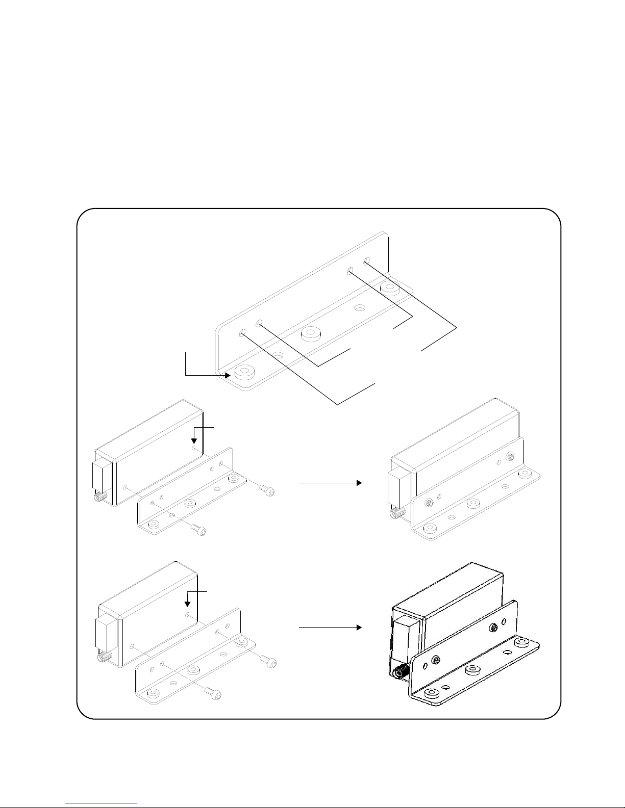
Y1170A and Y1171A Brackets
Figure 1-2 shows the brackets contained in the Y1170A and Y1171A mounting
kits and the mounting positions for the supported switches. The Y1170A bracket
(kit) is required for the L4491A platform and the Y1171A bracket (kit) is required
for the L4490A platform and the L4491A platform with Option 006.
The Y1170A and Y1171A kits contain hardware for installing five switches.
Keysight L4490A/L4491A User’s Guide 19
Page 20

About the Instrument Installing Switches/Attenuators in the RF Switch Platform
Y1170A
Y1171A
N1812
N1810
N1811
8762
8763
8764
8765
N1810
N1811
8762
8763
8765
N1812
8764
U937A, C
U937A,C
screw alignment is through switch and into bracket
screw alignment is through switch and into bracket
captive nut thread size = M4x0.7
switch mounting thread size = M3 x 0.5
Figure 1-2. Connecting Switches to the Y1170A and Y1171A Brackets.
20 Keysight L4490A/L4491A User’s Guide
Page 21

About the Instrument
Y1172A
87104A-C
87406B
87206A-C
87106A-C
87204A-C
87606B
screw alignment is through switch and into bracket
L7104A-C
L7106A-C
L7204A-C
L7206A-C
Allows viewing of switch path number
captive nut thread size = M4 x 0.7
Y1172 Bracket
Figure 1-3 shows the bracket contained in the Y1172A mounting kit and the
mounting position for the supported switches. The Y1172A bracket (kit) is used
with both the L4490A and L4491A platforms.
The Y1172A kit contains hardware for installing five switches.
Figure 1-3. Connecting Switches to the Y1172A Bracket.
Keysight L4490A/L4491A User’s Guide 21
Page 22

About the Instrument Installing Switches/Attenuators in the RF Switch Platform
Y1173A
87222C-E
screw alignment is through bracket and into switch
L7222C
bracket allows for two switches
captive nut thread size = M4 x 0.7
M2.5 x 0.45 x 6.5 deep
Y1173 Bracket
Figure 1-4 shows the bracket contained in the Y1173A mounting kit and the
mounting position for the supported switches. The Y1173A bracket (kit) is used
with both the L4490A and L4491A platforms.
The Y1173A kit contains hardware for installing six switches (two switches per
bracket).
Figure 1-4. Connecting Switches to the Y1173A Bracket.
22 Keysight L4490A/L4491A User’s Guide
Page 23
About the Instrument
Y1174A
84904K/L
screw alignment is through bracket and into switch
84904M
screw alignment is through bracket and into switch
84906K/L
84907K/L
84905M
84908M
captive nut thread size = M4 x 0.7
M3 x 0.5 x 6 deep
M3x0.5x6deep
Y1174 Bracket
Figure 1-5 shows the bracket contained in the Y1174A mounting kit and the
mounting positions for the supported attenuators. The Y1174A bracket (kit) is
used with both the L4490A and L4491A platforms.
The Y1174A kit contains hardware for installing five attenuators.
Figure 1-5. Connecting Switches to the Y1174A Bracket.
Keysight L4490A/L4491A User’s Guide 23
Page 24

About the Instrument Installing Switches/Attenuators in the RF Switch Platform
Y1175A
8494G/H
8767M
8495G/H
8766K
8767K
8768K
8769K
8769M*
8496G/H
8495K
8497K
8767M
8768M
mounting locations for L4490A
mounting Locations for L4491A
and L4491A with option 006
8769M*
*mounting location for 8769M in L4490A
and L4491A with option 006
captive nut (not shown) thread size = M4 x 0.7
L4490A/L4491A Opt. 006 Mounting
L4491A Mounting
mounting holes of switches = M3 x 0.5 x 5.1 deep
mounting holes of attenuators = 4-40 UNC x 5.1mm
mounting holes of switches = M3 x 0.5 x 5.1 deep
Y1175 Bracket
Figure 1-6 shows the bracket contained in the Y1175A mounting kit and the
mounting positions for the supported switches and attenuators. The Y1175A
bracket (kit) is used with both the L4490A and L4491A platforms.
The Y1175A kit contains hardware for installing five switches or attenuators.
Figure 1-6. Connecting Switches to the Y1175A Bracket.
24 Keysight L4490A/L4491A User’s Guide
Page 25

About the Instrument
34945EXT
L4490A Controller Box
switch tray (bracket mounting area)
DC Output Power Supplies
L4490A/L4491A Switch Trays and Options
The bracket-switch assemblies shown on the previous pages are mounted on the
switch trays within the L4490A and L4491A switch platforms. The Y1170A Y1175A bracket kits contain the required mounting hardware.
L4490A Switch Tray
Figure 1-7 shows the switch tray and bracket mounting location for the L4490A.
The switch tray is a grid with spacings of 45.72 mm x 45.72 mm between any two
holes in the ‘x’ and ‘y’ directions. Bracket mounting requires the L4490A top and
bottom covers to be removed (Figure 1-1). Screw alignment is upward through
the bottom of the tray and into the bracket’s captive nut.
Figure 1-8 shows example placement of switches and attenuators within the
L4490A.
Keysight L4490A/L4491A User’s Guide 25
Figure 1-7. L4490A Bracket Mounting Locations.
L4490A platforms with Digital IO and Relay Drive Option 004 reduces the
tray area available for switch and attenuator installation.
Page 26

About the Instrument Installing Switches/Attenuators in the RF Switch Platform
grid spacing = 45.72 mm x 45.72 mm
screw alignment is through bottom of tray and into bracket
Y1171A
Y1172A
Y1173A
(kit screws require T-20 Torx driver)
L4491A Standard Mounting Bays (Option 005)
Figure 1-9 show the switch bays and bracket mounting locations for the L4491A
with standard Option 005.
Figure 1-8. Example Switch and Attenuator Positioning within the L4490A.
26 Keysight L4490A/L4491A User’s Guide
Page 27

About the Instrument
34945EXT
L4491A Controller Box
switch bays
(bracket mounting area)
(2nd 34945EXT)
L4491A Opt. 002
rear mounting tray
mounting location for customer-provided fan
(60 mm tube axial fan, 50 mm hole to hole spacings)
L4491A Opt. 004 (digital IO and relay driver)
will restrict some brackets in the rear bay
Figure 1-9. L4491A Standard Option 005 Bracket Mounting Locations.
Bracket mounting within the switch bays requires the L4491A top, bottom, and
side covers to be removed (Figure 1-1). Screw alignment within the switch bays
is upward through the bay rail and into the bracket’s captive nut.
The rear mounting tray is a grid with spacings of 45.72 mm x 45.72 mm between
any two holes in the ‘x’ and ‘y’ directions. Screw alignment in the rear mounting
tray is downward through the bracket and into the captive nut on the tray.
Figure 1-10 shows example placement of switches and attenuators within the
L4491A.
Keysight L4490A/L4491A User’s Guide 27
Page 28
About the Instrument Installing Switches/Attenuators in the RF Switch Platform
Y1171A
Y1172A
Y1173A
Y1170A
Y1174A
Y1175A
grid spacing = 45.72 mm x 45.72 mm
captive nut thread size = M4x0.7
(kit screws require T-20 Torx driver)
Figure 1-10. Example Switch and Attenuator Positioning: L4491A with Option
005.
L4491A Bottom Switch Tray (Option 006)
Figure 1-11 shows the switch tray and bracket mounting location for L4491A
Option 006.
28 Keysight L4490A/L4491A User’s Guide
Page 29

About the Instrument
34945EXT
L4491A Controller Box
switch tray (bracket mounting area)
grid spacing = 45.72 mm x 45.72 mm
screw alignment is through bottom of tray and into bracket
L4491A Option 004
L4491A Option 002
(master)
(kit screws require T-20 Torx driver)
DC Output Power Supplies
The switch tray is a grid with spacings of 45.72 mm x 45.72 mm between any
two holes in the ‘x’ and ‘y’ directions. Bracket mounting with Option 006 requires
the L4491A top, bottom, and side covers to be removed (Figure 1-1). Screw
alignment is upward through the bottom of the tray and into the bracket’s
captive nut.
Example placement of switches and attenuators on the bottom tray is similar to
those shown in Figure 1-7 for the L4490A.
Figure 1-11. L4491A Bottom Switch Tray Option 006.
L4491A Option 006 platforms without Digital IO and Relay Drive Option
004 will have a small increase in the bracket mounting area.
Keysight L4490A/L4491A User’s Guide 29
Page 30

About the Instrument Installing Switches/Attenuators in the RF Switch Platform
L4491A Multiport Front Panel (Option 001)
Figure 1-12 shows L4491A multiport front panel Option 001. In order to use
Option 001 with standard switch bay Option 005, the rail assembly behind the
front panel must be removed. Figure 1-12 shows the assembly location and how
it is removed.
30 Keysight L4490A/L4491A User’s Guide
Page 31

About the Instrument
L4491A with multiport front panel Option 001
rail assembly removal required for
multiport switch installation
(remove screws from both sides)
back of front panel with rail assembly
removed and multiport switches installed
supported switches include:
87104A-C
87106A-C
87406B
87204A-C
87206A-C
87606B
L7104A-C
L7106A-C
L74204A-C
L74206A-C
Figure 1-12. Multiport Front Panel Option 001 with Standard Bay Option 005.
Keysight L4490A/L4491A User’s Guide 31
Page 32

About the Instrument Installing Switches/Attenuators in the RF Switch Platform
L4490A/L4491A Bracket Layout Guidelines
Switches installed in the L4490A platform or in the L4491A platform with Option
006 can be mounted in any orientation that optimizes or simplifies switch or
attenuator wiring.
For the L4491A with default Option 005, switches and attenuators may be
mounted in any of the "bays" and in any combination. Figure 1-13 shows the
typical number of given brackets (Y1170A - Y1175A) that can be installed in a
bay.
32 Keysight L4490A/L4491A User’s Guide
Figure 1-13. Bracket Layout Guidelines.
Page 33

2 Hardware Configuration
This chapter contains network, cabling, channel configuration, and switch wiring
information for the L4490A/L4491A RF Switch Platform and supported
switches/attenuators. Refer to this chapter for specific information on:
- choosing between a private LAN and site LAN network
- interconnections between the PC, RF switch platform, and the 34945EXT
- channel numbering and pairing
- internal/external power supply considerations
- connecting switches and attenuators to the distribution boards
Hardware Configuration
Keysight L4490A/L4491A User’s Guide 33
Page 34

Hardware Configuration Network Configuration
Network Configuration
This section contains information for choosing a network configuration (a private
or site LAN) in which to use the L4490A/L4491A.
Selecting a LAN Network
For the purposes of this manual, a private (isolated) LAN network is defined as a
network configuration in which instrument access is a direct connection between
the computer and the instrument, or to multiple instruments connected via a
dedicated router or switch. A site (company-wide) LAN is defined as a network in
which instrument access is available to many users at on-site and remote
locations.
The instrument’s application and/or your company’s IT (Information Technology)
department may have guidelines that help decide the type of network (private or
site) used. If a network configuration has not been determined, refer to the
following considerations concerning each type.
Private LAN Considerations
Among the basic parameters of a private LAN network to consider are security,
performance, reliability, and IP address availability.
Security: a private network generally involves a direct connection between the
PC and the instrument, or to multiple instruments using switches or routers.
Access to the instrument is limited to users on the private network, as opposed
to users on a site network that could locate and access the instrument from any
location. Private networks can reduce the possibility of tests being disrupted by
unplanned or unauthorized access. Code generation for test systems on a private
network is often simplified as provisions against unauthorized users may not be
required.
Performance: test systems where large amounts of data are transferred usually
have faster throughput on a private network. On a site network, heavy and
unpredictable LAN traffic affects each instrument (node) on the network. The
impact on a test system is that repeatability is difficult to achieve as latencies are
difficult to account for.
Reliability: private networks are fundamentally more reliable than site networks
as they host fewer users and are less complex than site networks. Private
networks are isolated from conditions that could bring down (crash) a site
network.
IP Address Availability: Every instrument (node) on a LAN (private or site) has an
IP (Internet Protocol) address. Due to the expanding use of the internet, the
number of site network IP addresses available is limited. By using a router with
Dynamic Host Configuration Protocol (DHCP) capability on a private network, the
router can assign an IP address to each instrument thus creating a sub-network
(subnet) that does not consume site IP addresses.
34 Keysight L4490A/L4491A User’s Guide
Page 35

Hardware Configuration
Site LAN Considerations
For applications requiring access by many users or by users at distributed sites, a
site LAN network is required. In addition to supporting multiple users, site LANs
often offer the advantage of being maintained by IT departments.
When using a site LAN, consult your IT department regarding LAN configuration
and security issues.
Instrument Configuration
Figure 2-1 shows the components and interconnections of the L4490A/L4491A
RF switch platform configuration.
Keysight L4490A/L4491A User’s Guide 35
Page 36

Hardware Configuration Instrument Configuration
CONTROL BUS
Agilent Technologies
34945 EXT
External uW Switch/Attenuator Driver
4321
4321
EXPANSIONBUS
PORT2
PORT1
NOTETHERNET
SEEMANUAL
!
+V
EXTERNAL
POWER INP UT
30VDC MAX
I/OACCESS
CONTROL BUS
Agile nt Te chn olog ies
34945 EXT
4321
4321
EXPANSIONBUS
PORT2
PORT1
NOTETHERNET
SEEMANUAL
!
+V
EXTERNAL
POWER INP UT
30VDC MAX
I/OACCESS
External uW Switch/Attenuator Driver
EXTERNAL
POW ER INPU
T
30 VD C M A X
+V
LAN cross-over cable for direct PC - L4490A/L4491A
+24V supplied from
34945EXT #1
34945EXT #2
(slave)
(master)
master 34945EXT connects to second 34945EXT
> external supply required for all 34945EXT (slave)
supply voltage applies to all
connection if PC is non Auto-MDIX (included)
L4491A Option 002
LAN
Hub/Switch
*
*
*
= standard LAN cables
or
> external supply voltages of 24V / 12V / 5V supported
through master’s Expansion Port 1; expansion ports
on slave modules are interchangeable
L4490A Option 004: digital IO and relay driver
modules external to the L4490A / L4491A
> up to seven slave 34945EXT modules allowed per
L4490A / L4491A
distribution board banks on
L4490A/L4491A
+24V supplied from
L4491A
slave 34945EXTs allowed external to
L4490A - require external power supply(s)
a given module
DC Output Power Supplies
5V: 1A
12V: 3A fused
24V: 0.6A
L4490A/L4491A
(user applications)
(42A Max.)
Figure 2-1. L4490A/L4491A RF Switch Platform Configuration.
36 Keysight L4490A/L4491A User’s Guide
Page 37

Hardware Configuration
PC to L4490A/L4491A. When connecting the PC directly to the
L4490A/L4491A, the LAN cross-over cable provided with the L4490A/L4491A is
used. If your PC supports Auto-MDIX or contains a LAN card with Gigabit data
transfer rates, the cross-over cable is not required. A standard LAN cable may be
used instead.
For network configurations (private or site) that include a LAN switch or router
between the PC and L4490A/L4491A, standard LAN cables are used. Do not use
the cross-over cable.
L4490A/L4491A to 34945EXT. The L4490A/L4491A controller box is
connected directly to the master 34945EXT and also to the second (slave)
34945EXT if installed in the L4491A (Option 002). +24V is supplied through this
connection. An external supply can also be used with the 34945EXTs for
applications requiring increased switching capacity.
34945EXT to 34945EXT. L4491A Option 002 adds a second (slave) 34945EXT
module. The second 34945EXT comes connected within the L4491A chassis to
the master 34945EXT using a standard LAN cable between the master’s
Expansion Bus Port 1 and Expansion Port 2 of the second EXT module. (The ports
of all slave 34945EXTs are interchangeable.) Up to eight 34945EXT modules
(including the master) can be used per L4490A or L4491A.
34945EXT to External Power Supplies. All slave 34945EXT modules external
to the L4490A or L4491A chassis must use an external power supply or supplies.
Note that the supply voltage (+24V, +12V, +5V) applies to all distribution board
banks on the 34945EXT.
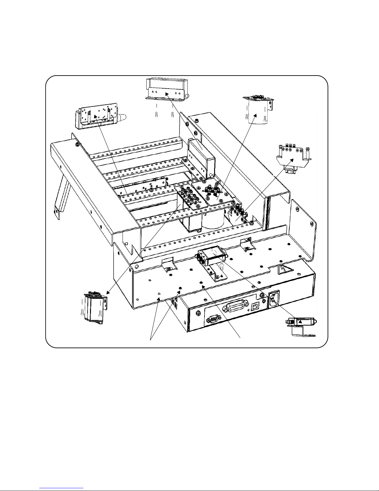
The 34945EXT Module
Microwave switches and attenuators are connected to the L4490A/L4491A
configuration through distribution boards (Y1150A - Y1155A) installed on the
34945EXT module (Figure 2-2).
The 34945EXT is divided into four banks organized by channel number. Any
distribution board may be installed in any bank, and multiple distribution boards
of the same type may be installed on the same 34945EXT module. Distribution
boards can be installed or removed with the L4490A/L4491A turned on;
however, the channel drive source (Figures 4-2, 4-3) must be off.
The “I/O ACCESS” LED on the EXT module indicates communication sequences
between the L4490A/L4491A controller box and the 34945EXT.
The Y1156A Verification Board
The optional Y1156A Verification board (not shown) is used to verify the signal
path from the PC to banks 1-4 on the 34945EXT. Verification of the path is
recommended before connecting switches or attenuators to the distribution
boards, or if a problem is suspected. See Chapter 4 for more information.
Keysight L4490A/L4491A User’s Guide 37
Page 38

Hardware Configuration Instrument Configuration
Y1150A
Y1153A
Y1154A
Y1151A
Y1152A
Y1155A
Bank 1
Ch 1101-1108
Ch 1111 - 111 8
Bank 3
Ch 1141-1148
Ch 1151-1158
Bank 4
Ch 1161-1168
Ch 1171-1178
Bank 1
Ch 1201-1208
Ch 1211-1218
Bank 2
Ch 1221-1228
Ch 1231-1238
Bank 3
Ch 1241-1248
Ch 1251-1258
Bank 4
Ch 1261-1268
Ch 1271-1278
Bank 2
Ch 1121-1128
Ch 1131-1138
34945EXT 1
34945EXT 2
Figure 2-2. The 34945EXT Module and Y1150A-Y1155A Distribution Boards.
38 Keysight L4490A/L4491A User’s Guide
Page 39

Hardware Configuration
Channel Numbering
The 34945EXT in the L4490A/L4491A RF switch platform uses the following
channel numbering scheme:
1<ext #><channel>
where:
ext # is the 34945EXT module and is a single digit in the range of 1 (master) to
2 (slave - a second 34945EXT in the L4491A). Note that up to seven slave EXT
modules may be used per master 34945EXT in the L4490A/L4491A.
channel is the channel number in the specified EXT module bank.
Channel numbers for two 34945EXT modules are shown in Figure 2-2 and also in
the table below.
34945EXT #1 (Master) 34945EXT #2 (Slave)
Bank Channels Channels Bank Channels Channels
Bank 1 1101 to
1108
Bank 2 1121 to
1128
Bank 3 1141 to1148 1151 to
Bank 4 1161 to
1168
1111 to
1118
1131 to
1138
1158
1171 to
1178
Bank 1 1201 to
1208
Bank 2 1221 to
1228
Bank 3 1241
to1248
Bank 4 1261 to
1268
1211 to
1218
1231 to
1238
1251 to
1258
1271 to
1278
An example of this syntax is:
ROUT:CLOS(@1141)
which closes channel 41 (bank 3) on 34945EXT module number 1 (Figure 2-1).
A range of channels is specified as:
ROUT:CLOS(@1101:1138)
which in this example closes channels 1 (bank 1) through 38 (bank 2) on 34945EXT
module number 1 (channel ranges can extend across banks).
Module- and Bank-Level Commands
Selected commands within the L4490A/L4491A SCPI command set contain
parameters that specify the 34945EXT itself, or a bank on the 34945EXT rather
than a channel list. These commands include:
Keysight L4490A/L4491A User’s Guide 39
Page 40

Hardware Configuration Instrument Configuration
ROUTe:RMODule:BANK:DRIVe:MODE
ROUTe:RMODule:BANK:LED:DRIVe:ENABle
ROUTe:RMODule:BANK:LED:DRIVe:LEVel
ROUTe:RMODule:BANK:PRESet
ROUTe:RMODule:DRIVe:LIMit
ROUTe:RMODule:DRIVe:SOURce:BOOT
ROUTe:RMODule:DRIVe:SOURce:IMMediate
For these commands, the 34945EXT address is in the form:
1<ext #><00>
where:
ext # is the 34945EXT module and is a single digit in the range of 1 (master) to 2
(a 2nd (slave) 34945EXT in the L4491A). For example,
ROUT:RMOD:BANK:PRES2,(@1200)
presets bank 2 on 34945EXT module 2.
Relay/Channel Relationship
The Keysight switches and attenuators listed in Table 1-2 are latching relays.
Therefore, there is a relay coil for each switch or attenuator position. In the
factory default configuration (
SYSTem:RMODule:RESet 1), a distribution board
channel is assigned to each relay coil. There are 16 channels per distribution
board.
Channel Pairing
Channel numbers on the distribution boards are arranged to facilitate channel
pairing for dual-coil switches and attenuators. In paired configurations, channels
1-8 are paired with 11-18 (bank 1), 21-28 with 31-38 (bank 2), 41-48 with 51-58
(bank 3), and 61-68 with 71-78 (bank 4). Paired channels are controlled by a
single command (e.g.
pair is specified. When a command (
OPEN or CLOSE) in which only the lower channel of the
OPEN or CLOSE) is sent, the operation
sends a drive pulse to either the first or second channel in the pair - either
opening or closing the channel.
For the channel pair 1/11, the following syntax:
ROUT:CLOS(@1101) - sends a drive pulse to the upper channel (1111)
ROUT:OPEN (@1101) - sends a drive pulse to the lower channel (1101)
Non-Paired Channels
When channel pairing is not enabled (e.g. for single-coil drive), the channel
numbers within the bank are not consecutive. The range of the 16 channels
remains 1-8/11-18 (bank 1) ... 61-68/71-78 (bank 4). See the previous page.
40 Keysight L4490A/L4491A User’s Guide
Page 41

Hardware Configuration
Internal/External Power Supply Considerations
As shown in Figure 2-1, the channel drive source for switches and attenuators in
the L4490A/L4491A RF Switch Platform is provided through the internal (or
external) power supply. The internal or external supply used must meet the
quiescent (steady-state) and switching current requirements of the switches in
your application. The following sections provide additional information on these
requirements and the recommended configuration of these supplies.
Internal Supply
The master 34945EXT (Figure 2-1) and optional second 34945EXT (Option 002)
can receive their power from either the internal +24V supply of the
L4490A/L4491A or from an external supply. When using the internal +24V supply
as the channel drive source, the switching current or the switching and quiescent
currents drawn from the supply must not exceed the supply’s specification of 600
mA continuous.
If this limit is exceeded, an overcurrent condition can occur which shuts down the
internal supply. When this happens, you must remove the device/condition
causing the overcurrent and cycle power on the L4490A or L4491A. See
“Overcurrent Conditions” in Chapter 5 for more information.
The quiescent current of 34945EXTs driven by the internal supply is accounted
for by the supply rating and is not included in quiescent current and switching
current calculations. Only the specified currents (quiescent, switching) of the
switch must be considered.
As an example, the Keysight 87104/87106A, B, C coaxial switches specify the
following:
Supply current (switching: pulse width =15 ms:Vcc = 24 VDC): 200 mA Nom
Supply current (quiescent): 50 mA Max
Using the L4490A/L4491A internal +24V supply, the current required for
actuating a 87104/87106 switch is:
[87104 / 87106 switch quiescent current] + [87104 / 87106 switching current]
[50 mA] + [200 mA]
= 250 mA (15 ms pulse, 50 mA quiescent)
The combination of switches and their power requirements often make it
difficult to determine if the capacity of the L4490A and L4491A internal
+24V supply will be exceeded. If overcurrent conditions occur repeatedly
regardless of recovery time (Chapter 5), the use of an external power
supply as the channel drive source may be required.
Keysight L4490A/L4491A User’s Guide 41
Page 42

Hardware Configuration Instrument Configuration
External Supply
Each 34945EXT can support up to 2A continuous using an externally connected
power supply (4.75V to 30V). The actual amount of power required by each EXT
module depends on the types of switches used.
When using an external power supply with either the master 34945EXT module
or second (slave) 34945EXT module or both, the supply must be able to provide
the quiescent current requirement of the EXT module(s), plus the quiescent and
switching currents of the switches themselves.
The power requirement of the 34945EXT is 1.2W. For supported external supply
voltages of 24V, 12V, and 5V, the current required for a single EXT module is as
follows:
current = power / voltage
24V: 1.2W / 24V = 50 mA
12V: 1.2W / 12V = 100 mA
5V: 1.2W / 5V = 240 mA
If multiple EXT modules are driven by a single external supply, the power
required from the supply increases by 1.2W for each EXT module present. Thus, if
two 34945EXT modules are driven by a single supply, the power value in the
previous equations becomes 2.4W.
The second consideration regarding the external supply are the quiescent current
and switching current specifications of the switch. Using the Keysight
87104/87106A, B, C coaxial switches from the internal supply example, the
switch specifications again are:
Supply current (switching: pulse width =15 ms:Vcc = 24 VDC): 200 mA Nom
Supply current (quiescent): 50 mA Max
The quiescent current required when switching does not occur is:
[34945EXT quiescent current from 24V] + [87104 / 87106 switch quiescent current]
[24V: 1.2W / 24V = 50 mA] + [50 mA] = 100 mA
For a single 34945EXT driven by an external supply, the current required for
actuating a 87104/87106 switch is:
[34945EXT quiescent current from 24V] + [switch quiescent current] + [switching
current]
[24V: 1.2W / 24V = 50 mA] + [50 mA] + [200 mA] = 300 mA (15 ms pulse, 100 mA
qui.)
42 Keysight L4490A/L4491A User’s Guide
Page 43

Hardware Configuration
In summary, quiescent current calculations must include the quiescent current of
the 34945EXT, plus the quiescent current requirement of each switch connected
to the module.
Similarly, switching current calculations must include the quiescent currents of
the EXT module and the switch, plus the switching (actuation pulse) current.
Keysight Switch/Attenuator Configuration
This section contains pin definitions and orientation to assist in connecting the
Keysight switches/attenuators listed in Table 1-2 to their corresponding Y115x
distribution boards.
Only general information is provided. Refer to the reference documents listed in
Table 1-2 for more information on the individual switches. Refer also to Table 1-2
for the number of switches allowed per distribution board.
Keysight L4490A/L4491A User’s Guide 43
Page 44
Hardware Configuration Keysight Switch/Attenuator Configuration
X864 2
97531
13579
2468
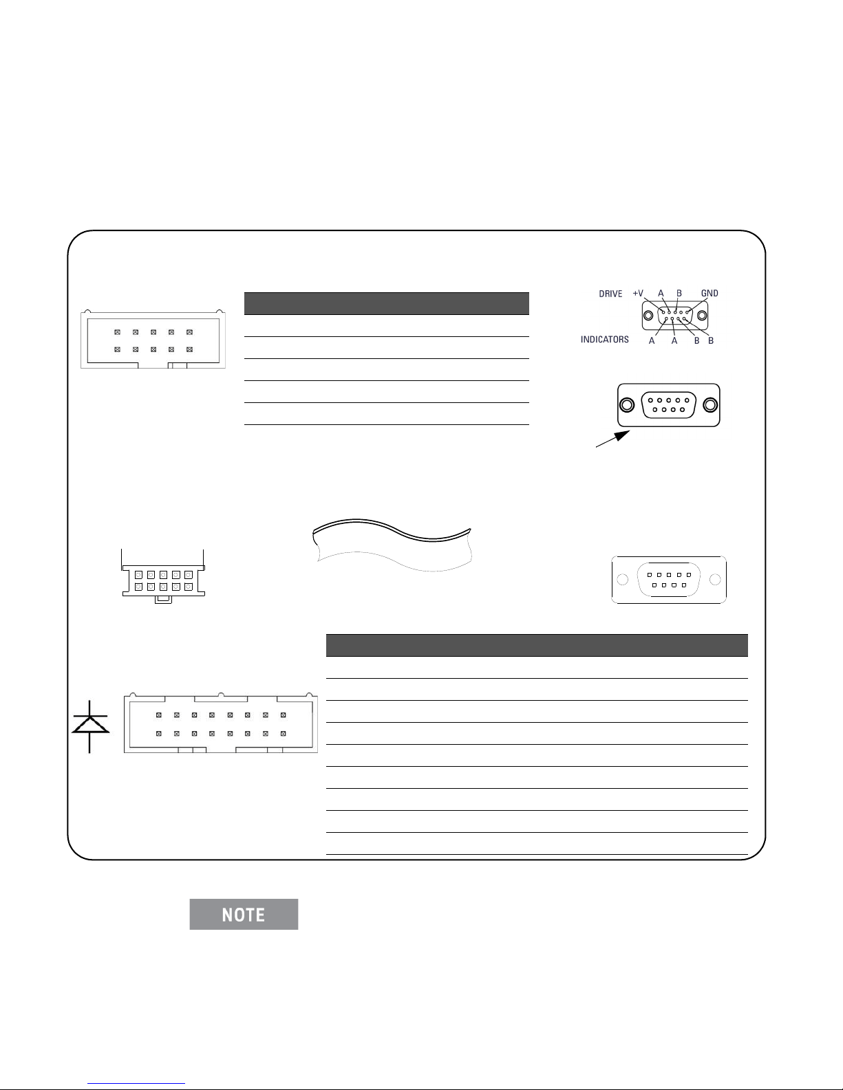
Pin Definition Pin Definition
1GND 2 Indicator B
3 No connection 4 +VI (LED indicator)
5 Drive B 6 Indicator A
7 Drive A 8 +VI (LED indicator)
9 +VR (relay drive voltage) 10 No connection
Keysight N1810/1/2
DC Connector Pin Out
9 7 5 3 1
8 6 4 2
Pin numbers are defined as shown -
not as printed on the connector
Y1150A/Y1152A/Y1154A
Distribution Board Connector
(N1810 / N1811 / N1812)
Y1170A/Y1171A Bracket Kit Cable
or
Y1157A Cable
(distribution board end)
LED1 Connector LED2 Connector
Pin Definition Pin Definition Pin Definition Pin Definition
1 +VI 2 SW1 - A 1 +VI 2 SW5 - A
3 +VI 4 SW1 - B 3 +VI 4 SW5 - B
5 +VI 6 SW2 - A 5 +VI 6 SW6 - A
7 +VI 8 SW2 - B 7 +VI 8 SW6 - B
9 +VI 10 SW3 - A 9 +VI 10 SW7 - A
11 +VI 12 SW3 - B 11 +VI 12 SW7 - B
13 +VI 14 SW4 - A 13 +VI 14 SW8 - A
15 +VI 16 SW4 - B 15 +VI 16 SW8 - B
Y1150A/Y1154A Distribution Board
LED Connector Pins
Y1150A/Y1152A/Y1154A Distribution Board
N181x Connector Pins
Distribution Board LED Connector
Y1170A/Y1171A Bracket Kit Cable
or
Y1157A Cable
(switch connector end)
1
2
9
10
1
2
15
16
Keysight N1810 / N1811 / N1812 Series Coaxial Switches
Figure 2-3 shows the pin definitions and orientation for the Y1150A, Y1152A, and
Y1154A distribution board connectors and the Keysight N181x series switches.
44 Keysight L4490A/L4491A User’s Guide
Figure 2-3. Keysight N1810 / N1811 / N1812 Pin Definition and Orientation.
The pin information for the Keysight switches shown in Figure 2-3
was taken from the reference documents listed in Table 1-2. Refer
to Table 1-2 for information on accessing these documents from
the Keysight web-site.
Page 45

Hardware Configuration
13 11 9 7 5 3 1
15
14 12 10 8 6 4 216
Keysight 87104 / 87106 / 87406
Keysight
Y1151A
Distribution Board Connector
(87104 / 87106 / 87406)
(L7104 / L7106 / L7204 / L7206)
Y1172A Bracket Kit Cable
or
87104 / 87106
L7104 / L7106 / L7204 / L7206
* Paths 1 and 4 of the 87104, L7104,
and L7204 are not connected
LED1 Connector LED2 Connector
Pin Definition Pin Definition Pin Definition Pin Definition
1 +VI 2 SW1 - Path 1 1 +VI 2 SW2 - Path 1
3 +VI 4 SW1 -Path 2 3 +VI 4 SW2 - Path 2
5 +VI 6 SW1 - Path 3 5 +VI 6 SW2 - Path 3
7 +VI 8 SW1 - Path 4 7 +VI 8 SW2 - Path 4
9 +VI 10 SW1 - Path 5 9 +VI 10 SW2 - Path 5
11 +VI 12 SW1 - Path 6 11 +VI 12 SW2 - Path6
13 +VI 14 Not Used 13 +VI 14 Not Used
15 +VI 16 Not Used 15 +VI 16 Not Used
Y1151A Distribution Board
LED Connector Pins
1
2
15
16
1
2
15
16
87406
Pin Definition Pin Definition
1+VR 2Indicator
Common
3 Drive Path 1 4 Ind icator 1
5 Drive Path 2 6 Ind icator 2
7 Drive Path 3 8 Ind icator 3
9 Drive Path 4 10 Indicator 4
11 Drive Path 5 12 Ind icator 5
13 Drive Path 6 14 Ind icator 6
15 GND 16 Open All Paths
Keysight 87104/87106/87406 - L7104/L7106/L7204/L7206 Coaxial
Switches
Figure 2-4 shows the pin definitions and orientation for the Y1151A distribution
board, the Keysight 87104, 87106, and 87406 series switches, and the L7104,
L7106, L7204, and L7206 L series switches.
Keysight L4490A/L4491A User’s Guide 45
Figure 2-4. Keysight 871x / 874x / L71x / L72x Pin Definition and Orientation.
Page 46

Hardware Configuration Keysight Switch/Attenuator Configuration
The pin information for the Keysight switches shown in Figure 2-4
was taken from the reference documents listed in Table 1-2. Refer
to Table 1-2 for information on accessing these documents from
the Keysight web-site.
46 Keysight L4490A/L4491A User’s Guide
Page 47

Hardware Configuration
13 11 9 7 5 3 1
15
14 12 10 8 6 4 216
Pin Definition Pin Definition
1+VR 2NC
3 Close 1 4 Open 1
5 Close 2 6 Open 2
7 Close 3 8 Open 3
9Close 4 10Open 4
11 Close 5 12 Open 5
13 Close 6 14 Open 6
15 GND 16 NC
Keysight 87204 / 87206 /
87606
Y1152A
Distribution Board Connector
(87204 / 87206 / 87606)
87606
87204* / 87206
* Paths 1 and 4 are not connected
for the 87204
LED 1 Connector LED 2 Connector
Pin Definition Pin Definition Pin Definition Pin Definition
1 +VI 2 SW1 - Close 1 1 +VI 2 SW1 - Close 5
3 +VI 4 SW1 -Open 1 3 +VI 4 SW1 -Open 5
5 +VI 6 SW1 - Close 2 5 +VI 6 SW1 - Close 6
7 +VI 8 SW1 - Open 2 7 +VI 8 SW1 - Open 6
9 +VI 10 SW1 - Close 3 9 +VI 10 SW2 - Ind A
11 +VI 12 SW1 - Open 3 11 +VI 12 SW2 - Ind B
13 +VI 14 SW1 - Close 4 13 +VI 14 SW3 - Ind A
15 +VI 16 SW1 - Open 4 15 +VI 16 SW3 - Ind B
Y1152A Distribution Board
LED Connector Pins
Pins 10, 12, 14, 16 of connector
LED2 are used for the N181x series
switches. See Figure 2-3 for N181x
connector pin definitions.
Y1172A Bracket Kit Cable
or
Y1159A Cable
1
2
15
16
1
2
15
16
Keysight 87204 / 87206/ 87606 Series Coaxial Switches
Figure 2-5 shows pin definitions and orientation for the Keysight Y1152A
distribution board and the 87204, 87206, and 87606 series switches.
Keysight L4490A/L4491A User’s Guide 47
Figure 2-5 Keysight 87204 / 87206 / 87606 Pin Definition and Orientation.
Page 48

Hardware Configuration Keysight Switch/Attenuator Configuration
The pin information for the Keysight switches shown in Figure 2-5
was taken from the reference documents listed in Table 1-2. Refer
to Table 1-2 for information on accessing these documents from
the Keysight web-site.
Keysight 8767/8/9M Microwave Single-Pole Multi-Throw Switches
Figure 2-6 identifies the terminals of the 8767/8/9M switches and typical
connections to the Y1153A distribution board (* 8767M shown).
48 Keysight L4490A/L4491A User’s Guide
Page 49

Hardware Configuration
Y1153A
Signal Path Control Data - 8767M (SP4T)
Port 1 2 3 +V
Supply
Port state Select Bypass Select Bypass Select Bypass
Switch actuating pin 8 5 9 4 2 1 10
11764-60001 wire color Gray Green White Yellow Red Brown Black
Signal Path Control Data - 8769M (SP6T)
Port 1 2 3 4 5 +V
Supply
Port state Select Bypass Select Bypass Select Bypass Select Bypass Select Bypass
Switch actuating pin 9 8 10 7 11 6 4 3 13 14 12
Pin dip wire color White Gray Black Violet Brn/Wht Blue Yellow Orange Org/Wht Yel/Wht Red/Wht
8767M*
8768M
8769M
8767M / 8768M connector
Distribution Board Connector
(876xM series)
108642
97531
Use Y1175A Bracket
and
Note: this is a 14-pin connector. Thus, the screw
terminals of the Y1153A (or Y1155) distribution board
must be used to connect the switch.
see Figure 2-7 for Y1153A LED connector pin definitions
1
2
9
10
Signal Path Control Data - 8768M (SP5T)
Port 1 2 3 4 +V
Supply
Port state Select Bypass Select Bypass Select Bypass Select Bypass
Switch
actuating
pin
76 85 9 4 21 10
11764-60
001 wire
color
Violet Blue Gray Green White Yellow Red Brown Black
Keysight L4490A/L4491A User’s Guide 49
Figure 2-6. Keysight 8767/8/9M Port Definitions and Connections.
Page 50

Hardware Configuration Keysight Switch/Attenuator Configuration
The terminal information for the Keysight switches shown in
Figure 2-6 was taken from the reference documents listed in Table
1-2. Refer to Table 1-2 for information on accessing these
documents from the Keysight web-site.
Keysight 84904/6/7 K/L and 84904/5/8M Programmable Step
Attenuators
Figure 2-7 identifies the pins of the 84904/6/7 K/L and 84904/5/8M step
attenuators and their connections to the Y1153A distribution board.
50 Keysight L4490A/L4491A User’s Guide
Page 51

Hardware Configuration
Pin Definition Pin Definition
1 Section 1 Thru Line 2 Section 1 Atten
3 No connection 4 Section 3 Thru Line
5 Section 2 Thru Line 6 Section 4 Thru Line
7 Section 4 Atten 8 Section 2 Atten
9 Section 3 Atten 10 +VR (relay drive voltage)
Distribution Board Connector
(8490x series)
Y1153A
8490x series
connector and pin
locations
8490x Series Pin and Attenuation Guide
Section 1 2 3 4 +V
Suppl
yThru
Line
Attn
Card
Thr
u
Lin
e
Attn
Card
Thr
u
Lin
e
Atte
n
Card
Thr
u
Lin
e
Atte
n
Car
d
Actuating pin 1 2 5 8 4 9 6 7 10
Attenuation (dB) 84904K/L 0 1 0 2 0 4 0 4
Attenuation (dB) 84906K/L 0 10 0 20 0 30 0 30
Attenuation (dB) 84907K/L 0 10 0 20 0 40
LED1 Connector LED2 Connector
Pin Definition Pin Definition Pin Definition Pin Definition
1 +VI 2 P101 Atten 1 1 +VI 2 P102 Atten 1
3 +VI 4 P101 Thru 1 3 +VI 4 P102 Thru 1
5 +VI 6 P101 Atten 2 5 +VI 6 P102 Atten 2
7 +VI 8 P101 Thru 2 7 +VI 8 P102 Thru 2
9 +VI 10 P101 Atten 3 9 +VI 10 P102 Atten 3
11 +VI 12 P101 Thru 3 11 +VI 12 P102 Thru 3
13 +VI 14 P101Atten 4 13 +VI 14 P102 Atten 4
15 +VI 16 P101 Thru 4 15 +VI 16 P102 Thru 4
Y1153A Distribution Board LED Connector Pins
Distribution Board LED Connector
108642
97531
Y1174A Bracket Kit Cable
or
1
2
9
10
1
2
15
16
Keysight L4490A/L4491A User’s Guide 51
Figure 2-7. Keysight 84904/6/7 K/L Attenuator Pin Definitions and Connections.
Page 52

Hardware Configuration Keysight Switch/Attenuator Configuration
The terminal information for the Keysight switches shown in
Figure 2-7 was taken from the reference documents listed in Table
1-2. Refer to Table 1-2 for information on accessing these
documents from the Keysight web-site.
Keysight 8494/5/6/7 Programmable Step Attenuators
Figure 2-8 identifies the pins of the 8494/5/6/7 step attenuators and typical
connections to the Y1153A distribution board.
52 Keysight L4490A/L4491A User’s Guide
Page 53

Hardware Configuration
849x Series Pin and Attenuation Guide
Section 1 2 3 4 +V
Suppl
ySoleniod Coil Thru
Line
Attn
Card
Thr
u
Lin
e
Attn
Card
Thru
Line
Atte
n
Card
Thru
Line
Atte
n
Car
d
Cable wire color code pur
ple
yellowblackgreenorangeblue brownwhiteRed
Actuating pin 5 6 7 8 9 10 11 12 1
Attenuation (dB) 8494G/H 0 1 0 2 0 4 0 4
Attenuation (dB) 8495G/H/K 0 10 0 20 0 40
Attenuation (dB) 8496G/H 0 10 0 20 0 40 0 40
Y1153A
red
black
green
orange
blue
brown
white
purple
yellow
849x series plug
and pin locations
Use Y1175A Bracket Kit
Figure 2-8. Keysight 8494 /5 / 6 / 7 Attenuator Pin Definitions and Connections.
The terminal information for the Keysight switches shown in
Figure 2-8 was taken from the reference documents listed in Table
1-2. Refer to Table 1-2 for information on accessing these
documents from the Keysight web site.
Keysight L4490A/L4491A User’s Guide 53
Page 54

Hardware Configuration Keysight Switch/Attenuator Configuration
Keysight 849xG/H/K Programmable Step Attenuators Option 016
Figure 2-9 identifies the pins of the 8494/5/6/7 Option 016 Step Attenuators and
typical connections to the Y1153A distribution board.
54 Keysight L4490A/L4491A User’s Guide
Page 55

Hardware Configuration
Pin Definition Pin Definition
1 Section 1 Thru Line 2 Section 1 Atten
3 No connection 4 Section 3 Thru Line
5 Section 2 Thru Line 6 Section 4 Thru Line
7 Section 4 Atten 8 Section 2 Atten
9 Section 3 Atten 10 +VR (relay drive voltage)
Distribution Board Connector
(8490x, 849x Opt. 016 series)
Y1153A
849x series Opt. 016
connector and pin
locations
849x Series Opt. 016 Pin and Attenuation Guide
Section 1 2 3 4 +V Supply
Soleniod Coil Thru
Line
Attn
Card
Thr
u
Lin
e
Attn
Card
Thru
Line
Atte
n
Card
Thru
Line
Atte
n
Car
d
Cable wire color code pur
ple
yellowblackgreenorangeblue brownwhiteRed
Actuating pin 1 2 5 8 4 9 6 7 10
Attenuation (dB) 8494G/H 0 1 0 2 0 4 0 4
Attenuation (dB) 8495G/H/K 0 10 0 20 0 40
Attenuation (dB) 8496G/H 0 10 0 20 0 40 0 40
LED1 Connector LED2 Connector
Pin Definition Pin Definition Pin Definition Pin Definition
1 +VI 2 P101 Atten 1 1 +VI 2 P102 Atten 1
3 +VI 4 P101 Thru 1 3 +VI 4 P102 Thru 1
5 +VI 6 P101 Atten 2 5 +VI 6 P102 Atten 2
7 +VI 8 P101 Thru 2 7 +VI 8 P102 Thru 2
9 +VI 10 P101 Atten 3 9 +VI 10 P102 Atten 3
11 +VI 12 P101 Thru 3 11 +VI 12 P102 Thru 3
13 +VI 14 P101Atten 4 13 +VI 14 P102 Atten 4
15 +VI 16 P101 Thru 4 15 +VI 16 P102 Thru 4
Y1153A Distribution Board LED Connector Pins
Distribution Board LED Connector
108642
97531
Y1158A Cable
1
2
9
10
1
2
15
16
The Y1153A module
works with 849x series
attenuators even
though the module
silkscreen does not
show it.
Keysight L4490A/L4491A User’s Guide 55
Figure 2-9. Keysight 8494 /5 / 6 / 7 Attenuator Pin Definitions and Connections.
Page 56

Hardware Configuration Keysight Switch/Attenuator Configuration
14 12 10 8 6 4 2
131197531
108642
97531
Pin Definition Pin Definition
1 +VR 2 +VI
3 Drive A 4 Indicator A
5 Drive B 6 Indicator B
7N.C. 8N.C.
9GND 10N.C.
11 N.C. 12 N.C.
13 N.C. 14 N.C.
Keysight 87222 / L7222
DC Connector Pin Out
Y1154A
Distribution Board Connector
(87222 / L7222)
LED1 Connector LED2 Connector
Pin Definition Pin Definition Pin Definition Pin Definition
1 +VI 2 SW1 - A 1 +VI 2 SW5 - A
3 +VI 4 SW1 - B 3 +VI 4 SW5 - B
5 +VI 6 SW2 - A 5 +VI 6 SW6 - A
7 +VI 8 SW2 - B 7 +VI 8 SW6 - B
9 +VI 10 SW3 - A 9 +VI 10 SW7 - A
11 +VI 12 SW3 - B 11 +VI 12 SW7 - B
13 +VI 14 SW4 - A 13 +VI 14 SW8 - A
15 +VI 16 SW4 - B 15 +VI 16 SW8 - B
Y1150A/Y1154A Distribution Board
LED Connector Pins
Distribution Board LED Connector
The N181x series switches can also
be used with the Y1154A distribution
board. See Figure 2-3 for N181x
connector pin definitions.
Y1173A Bracket Kit Cable
or
Y1158A Cable
(distribution board end)
Y1173A Bracket Kit Cable
or
Y1158A Cable
(switch connector end)
1
2
13
14
1
2
15
16
Keysight 87222 and L7222 Coaxial Switches
Figure 2-9 shows the pin definitions and orientation for the Y1154A distribution
board and the Keysight 87222 and L7222 coaxial transfer switches.
56 Keysight L4490A/L4491A User’s Guide
Figure 2-9. Keysight 87222 / L7222 Pin Definition and Orientation.
The pin information for the Keysight switches shown in Figure 2-9
was taken from the reference documents listed in Table 1-2. Refer
to Table 1-2 for information on accessing these documents from
the Keysight web-site.
Page 57

Hardware Configuration
8762A/B/C
8763A/B/C
8764A/B/C
‘Diagram shows 8762 and 8764 connected
with position indication.
8762F
Y1155A
LED1 Connector LED2 Connector
Pin Definition Pin Definition Pin Definition Pin Definition
1 +VI 2 SW1 - A 1 +VI 2 SW1 - B
3 +VI 4 SW2 - A 3 +VI 4 SW2 - B
5 +VI 6 SW3 - A 5 +VI 6 SW3 -B
7 +VI 8 SW4 - A 7 +VI 8 SW4 - B
9 +VI 10 SW5 - A 9 +VI 10 SW5 -B
11 +VI 12 SW6 - A 11 +VI 12 SW6 - B
13 +VI 14 SW7 - A 13 +VI 14 SW7 - B
15 +VI 16 SW8- A 15 +VI 16 SW8 - B
Y1155A Distribution Board LED Connector Pins
(SW# - B)
(SW# - A)
L4491A: use Y1170A bracket
L4490A: use Y1171A bracket
(paired)
Keysight 8762 / 8763 / 8764 Series Coaxial Switches
Figure 2-10 identifies the 8762/8763/8764 switch terminals and typical
connections to the Y1155A distribution board (w/ position indication).
Figure 2-10. Keysight 8762 / 8763 / 8764 Terminal Connections.
Keysight L4490A/L4491A User’s Guide 57
Page 58

Hardware Configuration Keysight Switch/Attenuator Configuration
The terminal information for the Keysight switches shown in
Figure 2-10 was taken from the reference documents listed in
Table 1-2. Refer to Table 1-2 for information on accessing these
documents from the Keysight web-site.
Keysight 8765 Series Coaxial Switches
Figure 2-11 identifies the terminals of the 8765 switches and typical connections
to the Y1155A distribution board (with position indication).
58 Keysight L4490A/L4491A User’s Guide
Page 59

8765F
8765A/B/C/D
The’ common negative’ and
‘polarity reversal’ configurations
of the 8765 series switch are not
supported.
Y1155A
LED1 Connector LED2 Connector
Pin Definition Pin Definition Pin Definition Pin Definition
1 +VI 2 SW1 - A 1 +VI 2 SW1 -B
3 +VI 4 SW2 - A 3 +VI 4 SW2 - B
5 +VI 6 SW3 - A 5 +VI 6 SW3 -B
7 +VI 8 SW4 - A 7 +VI 8 SW4 - B
9 +VI 10 SW5 - A 9 +VI 10 SW5 - B
11 +VI 12 SW6 - A 11 +VI 12 SW6 - B
13 +VI 14 SW7 - A 13 +VI 14 SW7 - B
15 +VI 16 SW8 - A 15 +VI 16 SW8 - B
Distribution Board LED Connector
(SW# - B)
(SW# - A)
L4491A: use Y1170A bracket
L4490A: use Y1171A bracket
(paired)
( ) = solder terminal pins
1
2
15
16
Y1155A Distribution Board LED Connector Pins
Hardware Configuration
Keysight L4490A/L4491A User’s Guide 59
Figure 2-11. Keysight 8765 Terminal Connections.
The terminal information for the Keysight switches shown in
Figure 2-11 was taken from the reference documents listed in
Table 1-2. Refer to Table 1-2 for information on accessing these
documents from the Keysight web-site.
Page 60

Hardware Configuration Keysight Switch/Attenuator Configuration
Keysight 8766/7/8/9K Microwave Single-Pole Multi-Throw Switches
Figure 2-12 identifies the terminals of the 8766/7/8/9K switches and typical
connections to the Y1155A distribution board (* 8767K shown).
60 Keysight L4490A/L4491A User’s Guide
Page 61

Signal Path Control Data - 8766K (SP3T) + V Supply
Switching section 1 2
Section state Select Bypass Select Bypass
Std. Viking pin 6 5 8 7 1
Std. Viking wire color Yellow Violet Green Black Red
Signal Path Control Data - 8767K (SP4T) +V Supply
Switching section 1 2 3
Section state Select Bypass Select Bypass Select Bypass
Std. Viking pin 8 7 10 9 6 5 1
Std. Viking wire color Green Black Blue Orange Yellow Violet Red
Signal Path Control Data - 8769K (SP6T)
Switching section 1 2 3 4 5
Section state Select Bypass Select Bypass SelectBypass Select Bypass Select Bypass
Std. Viking pin 12 11 8 7 10 9 6 5 3 4
Std. Viking wire color White Brown Green Black Blue Orange Yellow Violet Gray Wht/Red
Signal Path Control Data - 8768K (SP5T)
Switching section 1 2 3 4
Section state Select Bypass Select Bypass Select Bypass Select Bypass
Std. Viking pin 12 11 8 7 10 9 6 5
Std. Viking wire color White Brown Green Black Blue Orange Yellow Violet
8766K
8767K*
8768K
8769K
Pin 1 (red wire) connected to +24V
Y1155A
Use Y1175A Bracket Kit
Pin 1 (red wire) connected to +24V
*
Green
Black
Blue
Orange
Yellow
Violet
Red
Hardware Configuration
Keysight L4490A/L4491A User’s Guide 61
Figure 2-12. Keysight 8766/7/8/9K Section Definitions and Connections.
Page 62

Hardware Configuration Keysight Switch/Attenuator Configuration
Y1155A
LED1 Connector LED2 Connector
Pin Definition Pin Definition Pin Definition Pin Definition
1+VI 2SW1 1+VI 2 SW11
3+VI 4SW2 3+VI 4SW12
5+VI 6SW3 5+VI 6SW13
7+VI 8SW4 7+VI 8SW14
9 +VI 10 SW5 9 +VI 10 SW15
11 +VI 12 SW6 11 +VI 12 SW16
13 +VI 14 SW7 13 +VI 14 SW17
15 +VI 16 SW8 15 +VI 16 SW18
Y1155A Distribution Board LED Connector Pins
Distribution Board LED Connector
Use Y1170A or Y1171A Bracket Kit
(no cables)
(un-paired)
1
2
15
16
The terminal information for the Keysight switches shown in
Figure 2-12 was taken from the reference documents listed in
Table 1-2. Refer to Table 1-2 for information on accessing these
documents from the Keysight web-site.
Keysight U9397A / U9397C FET Solid State Switches
Figure 2-13 identifies the terminals of the U9397A/C switches and typical
connections to the Y1155A distribution board (with position indication).
62 Keysight L4490A/L4491A User’s Guide
Figure 2-13. Keysight U9397A / U9397C Connector Definitions and Connections.
Page 63

Hardware Configuration
The terminal information for the Keysight switches shown in
Figure 2-13 was taken from the reference documents listed in
Table 1-2. Refer to Table 1-2 for information on accessing these
documents from the Keysight web-site.
Keysight L4490A/L4491A User’s Guide 63
Page 64

Hardware Configuration Keysight Switch/Attenuator Configuration
64 Keysight L4490A/L4491A User’s Guide
Page 65

Software Installation and Configuration
3 Software Installation and
Configuration
This chapter contains information on IO libraries and drivers required to program
the L4490A/L4491A from selected development environments. The chapter also
provides information on configuring the instrument’s LAN and GPIB interfaces
and on updating the instrument firmware.
Refer to this chapter for specific information on:
- development environments and IO library/driver requirements
- installing the Keysight IO Libraries
- installing IVI (instrument) drivers
- LAN and GPIB configuration using Keysight Connection Expert
- updating the L4490A/L4491A firmware and IVI Drivers
Keysight L4490A/L4491A User’s Guide 65
Page 66

Software Installation and Configuration Software Requirements
Software Requirements
The manner and environments available to program the L4490A/L4491A are
dependent upon the IO libraries and drivers installed. The IO software included
with the L4490A/L4491A is contained on the following CDs:
- Keysight Automation-Ready CD: Keysight IO Libraries Suite 15.0
- Keysight L4490A/L4491A Product Reference CD-ROM:
IVI-C, IVI-COM Drivers
National Instrument LabVIEW
Table 3-1 summarizes the environments, IO driver recommendations, and the
location (media) where the specific drivers and libraries can be found.
Table 3-1. L4490A/L4491A Development Environments and Drivers.
Interface Development Environment IO Driver Recommendations
LAN Web-enabled instrument interface
> SCPI Command Interface window
LAN, GPIB Keysight Connection Expert
> Interactive IO window
LAN, GPIB Microsoft® Visual Studio® 6.0
> Visual C++
LAN, GPIB Microsoft® Visual Studio® 6.0
> Visual Basic
LAN, GPIB Microsoft® Visual Studio® .NET
> CSharp, C++, Visual Basic 7.0
LAN, GPIB Keysight VEE
LAN, GPIB National Instruments LabVIEW
LAN, GPIB National Instruments LabWindows/CVI
Java-enabled Web browser
(available from www.java.com)
Keysight KeysightIO Libraries
VISA - Keysight IO Libraries CD
or
IVI-C - Product Reference CD
VISA-COM - Keysight IO Libraries
or
IVI-COM - Product Reference CD
VISA-COM - Keysight IO Libraries
or
IVI-COM - Product Reference CD
IVI-COM - Product Reference CD
LabVIEW Plug&Play (with L44xx
native mode driver)
IVI-C - Product Reference CD
IVI-C - Product Reference CD
66 Keysight L4490A/L4491A User’s Guide
Page 67

Software Installation and Configuration
Installing the Keysight IO Libraries
The Keysight IO Libraries include the VISA and VISA-COM libraries used for programming the L4490A/L4491A in Microsoft development environments (Table
3-1). The VISA and VISA-COM libraries allow you to send commands from the
L4490A/L4491A SCPI command set to the instrument (see “L4490A/L4491A
Programmers Reference Help” on the Product Reference CD-ROM). The IO
libraries also include the ‘Configuration Expert’ utility described later in this
chapter.
Programming the L4490A/L4491A from the instrument’s Web interface
requires a Web-browser but no additional (i.e. user-installed) instrument
drivers or libraries. The Web interface provides full access to RF switch
platform functionality and its IO command log feature logs (SCPI)
commands sent to the instrument via interface dialog boxes. The
commands can then be copied and transferred to other development
environments. Refer to Chapter 4 for more information on programming
using the Web interface.
The Keysight IO Libraries must be installed prior to installing drivers (e.g.
IVI-C, IVI-COM) from the L4490A/L4491A Product Reference CD or from
any other source.
The IO Libraries are contained on the Keysight Automation-Ready CD or may be downl
oaded from the Keysight website at:
http://www.Keysight.com/find/iosuite
Before installing the IO libraries, review Table 3-2 to verify that your computer
meets the specifications required for the software.
Table 3-2. Keysight IO Libraries Suite System Requirements.
Processor 450 MHz Intel Pentium® II or higher
Operating System Windows XP Professional or Home Edition (Service Pack 1 or later)
Windows 2000 Professional (Service Pack 4 or later)
Web Browser Microsoft Internet Explorer 5.01 or greater (recommended)
Available Memory 128 MB (256 MB or greater recommended)
Keysight L4490A/L4491A User’s Guide 67
Page 68

Software Installation and Configuration Software Requirements
Available Disk Space 225 MB required for installation:
- 160 MB for Microsoft .NET Framework
- 65 MB for Keysight IO Libraries Suite
175 MB required for operation:
- 110 MB for Microsoft .NET Framework
- 65 MB for Keysight IO Libraries Suite
Video Super VGA (800x600) with 256 colors
Close all applications on your computer. Insert the Keysight Automation-Ready
CD into the CD-ROM drive. Follow the instructions as prompted for a typical
installation. Accept all default directories specified.
If the IO libraries installation does not start automatically, select Start > Run from
the Windows Start menu and type <drive>:\autorun\auto.exe where <drive> is
the designator of the CD-ROM drive.
If another vendor’s implementation of VISA (Virtual Instrument Software
Architecture) is currently installed on your computer, continue
installation of the Keysight IO Libraries by installing Keysight VISA in
side-by-side mode. More information on side-by-side operation can be
found in the “IO Libraries Suite Help” (available after installation is
complete) under “Using Keysight’s and Other Vendors’ Products
Together”.
After the IO libraries have been successfully installed, you have the option of
starting ‘Connection Expert’ or closing the installation wizard. If you choose to
start Connection Expert, continue with the ”Interface Configuration” section of
this chapter. Otherwise, continue with instrument driver installation as described
below.
Installing Instrument Drivers
Interchangeable Virtual Instrument (IVI) drivers are available for programming
the L4490A/L4491A using Microsoft development environments, Keysight VEE,
or National Instruments LabVIEW (see Table 3-1). Insert the Keysight
L4490A/L4491A Product Reference CD-ROM into your computer. The installation program will open the window shown in Figure 3-1.
68 Keysight L4490A/L4491A User’s Guide
Page 69

Software Installation and Configuration
Installing the Keysight IO Libraries also installs the Interchangeable
Virtual Instrument (IVI) Shared Components. The IVI Shared Components
are required before IVI drivers (e.g. IVI-COM, IVI-C) can be installed from
the L4490A/L4491A Product Reference CD.
Figure 3-1. Product Reference CD-ROM Software (& Driver) Menu.
Install the appropriate driver based on the development environment you are
using. Accept all default directories specified during installation if prompted.
Setup type “Typical” is applicable for most users. (As previously noted, installing
the Keysight IO Libraries installs the IVI Shared Components.)
Adding Instruments to the Interface
This section contains information for configuring the L4490A/L4491A LAN and
GPIB interfaces using the Keysight IO Libraries ‘Connection Expert’ utility.
Configuring the LAN Interface
With the L4490A/L4491A turned on and connected to the PC (Chapter 2: Figure
2-1), start the Connection Expert utility by clicking the ‘IO (control)’ icon and
selecting “Keysight Connection Expert” from the pop up menu as shown in Figure
3-2.
Keysight L4490A/L4491A User’s Guide 69
Page 70

Software Installation and Configuration Adding Instruments to the Interface
clicking the icon opens the
pop-up menu
The procedure for using Keysight Connection Expert to locate and
configure the L4490A/L4491A is independent of the type of network you
are using (private or site) and the network devices present (switches or
routers).
Figures of the following Keysight Connection Expert windows represent
Keysight IO Libraries Suite 15.0.
Figure 3-2. Starting Connection Expert.
Locating the Instruments
Keysight Connection Expert opens with a “welcome screen” and window similar to
that shown in Figure 3-3. The computer interfaces available are configured during
installation of the Keysight IO Libraries and are displayed in the left column
70 Keysight L4490A/L4491A User’s Guide
Page 71

Software Installation and Configuration
Explorer Pane
Properties Pane
(Explorer pane), the properties of the configured interface are displayed in the right
column (Properties pane).
Figure 3-3. Keysight Connection Expert (ACE) Opening Window.
To search the network for instruments, click on “Add Instrument” located on the
Connection Expert tool bar. From the “Add Instrument” window, select the LAN
(TCPIP0) interface and click on ‘OK’. See Figure 3-4.
Keysight L4490A/L4491A User’s Guide 71
Page 72

Software Installation and Configuration Adding Instruments to the Interface
Figure 3-4. Keysight Connection Expert “Add Instrument” Window.
After clicking ‘OK’, Keysight Connection Expert (version 15) performs an automatic find (search) of all instruments on the same subnet as the computer. An
example of instruments found on a subnet is shown in Figure 3-5.
The “Add LAN Instruments” window identifies the instrument’s IP address, MAC
address, host name, and product number. In the example of Figure 3-5, the
instrument is connected to the PC via a LAN switch with no DHCP server present.
Thus, the host name is not registered and access to the instrument is through its
IP address.
“Select” the desired instruments from the list and then click ‘OK’. Communication
paths to the instruments are verified and the instruments are added to the configured interface. The instruments appear in the Keysight Connection Expert
Explorer pane (Figure 3-3). Selecting the instrument in the Explorer pane displays its properties in the Properties pane.
72 Keysight L4490A/L4491A User’s Guide
Page 73

Software Installation and Configuration
Click to add selected instrument
to the configured interface
Figure 3-5. Instruments Found on a Local Subnet.
About IP Addresses and Host names
Dynamic Host Configuration Protocol (DHCP) and Automatic IP are enabled on
the L4490A/L4491A when shipped from Keysight. This allows the instrument to
automatically obtain an address on the network. If there is a DHCP server on the
network, the server will assign the address to the instrument.
If there is not a DHCP server on the network, the L4490A/L4491A will automatically determine the address to use. The address will be in the range 169.254.1.1
to 169.254.255.255. If available, the instrument will try to acquire its default setting of 169.254.44.88.
Host Names The L4490A/L4491A has a default host name. The format of the
host name is:
a-l449xa-yyyyy
where ‘yyyyy’ are the last five digits of the instrument’s serial number.
The instrument host name is reported by Keysight Connection Expert for network
Keysight L4490A/L4491A User’s Guide 73
Page 74

Software Installation and Configuration Adding Instruments to the Interface
servers that support Dynamic Domain Name Service (DNS). For network servers
that do not support Dynamic DNS, only the IP address is reported.
Instrument Addressing During programming, the L4490A/L4491A is accessed
through its address string which consists of an IP address:
TCPIP0::169.254.44.88::inst0::INSTR
or host name:
TCPIP0::A-L449XA-00118.Keysight.com::inst0::INSTR
A powerful tool for programming the L4490A/L4491A is the instrument’s
Web interface. The Web interface provides full access to
L4490A/L4491A functionality and its IO command log feature logs (SCPI)
commands sent to the instrument via interface dialog boxes. The
commands can then be copied and transferred to other development
environments. Chapter 4 contains detailed information on accessing and
using the Web interface.
Configuring the GPIB Interface
The following information assumes a GPIB interface card has been
installed in your computer.
The L4490A/L4491A is an Keysight web-enabled instrument that offers a
user interface which requires no user-installed IO drivers. Access to the
instrument via the Web interface, however, is only available through the
LAN connection.
Programming access to the L4490A/L4491A is also available through the
instrument’s optional GPIB interface. The GPIB connector is located on the rear
panel of the instrument. Simultaneous LAN and GPIB connections to the
instrument are allowed. The following information describes how instruments on
the GPIB interface are configured using Keysight Connection Expert.
GPIB Connections
GPIB cables can be connected to the PC in a “star” (all cables connect directly to
the computer) or “linear” (instrument to instrument) configuration.
Starting Keysight Connection Expert
Start Connection Expert by clicking the Keysight Control icon and selecting “Key-
74 Keysight L4490A/L4491A User’s Guide
Page 75

Software Installation and Configuration
GPIB interface present
sight Connection Expert” from the pop-up menu (Figure 3-2). If a GPIB card is
installed in your computer, the (GPIB) interface was configured during installation of the Keysight IO libraries and is displayed in the left column (Explorer pane)
of the “welcome” screen (Figure 3-6).
Figure 3-6. Adding Instruments to the GPIB Interface.
Adding Instruments to the GPIB Configuration
In the Connect Expert window, select “Add Instrument” on the tool bar. Select
the GPIB interface in the “Add Instrument” window and click ‘OK’ (Figure 3-6).
In the ‘New GPIB Instrument’ window, select the L4490A/L4491A’s GPIB address
(note: factory-set address = 9) and click ‘OK’.
Connection Expert will attempt to establish a communication path to the instrument. If the L4490A/L4491A is at the address specified, the instrument will be
added to the list of GPIB-configured instruments.
Keysight L4490A/L4491A User’s Guide 75
Page 76

Software Installation and Configuration Adding Instruments to the Interface
If the L4490A/L4491A GPIB address is unknown, the address can be
queried from the LAN interface by sending the following command from
the ‘Interactive IO’ or ‘SCPI Command Interface’ window:
SYSTEM:COMMunicate:GPIB:ADDRess?
See “Using Interactive IO” for more information.
The GPIB Address String
When programming the L4490A/L4491A over GPIB, the instrument’s GPIB
address is included in the address string as shown below:
GPIB0::9::INSTR
Changing the GPIB Address
The L4490A/L4491A GPIB address can only be changed programmatically. The
command used to set the GPIB address is:
SYSTem:COMMunicate:GPIB:ADDRess < address >
The command can be abbreviated by including only the upper-case letters in the
command syntax. The command can be sent from the ‘Interactive IO’ window, or
from the ‘SCPI Command Interface’ window - via a LAN connection.
When the address is changed, the new GPIB address IS NOT updated in Connection Expert if the instrument was previously configured.
From the Connection Expert window, highlight the instrument whose address
was changed and then select ‘Change Properties ...”. Within the configurable
properties window, change the address to the new address setting and select
‘OK’ (Figure 3-6).
The Web-Enabled Instrument Interface and Interactive IO
The Web-enabled instrument interface featured in Chapter 4 is not available
from the GPIB interface.
For GPIB operations, the Connection Expert ‘Interactive IO’ utility can be used to
send SCPI commands from the L4490A/L4491A command set to the instrument.
See the section “Using Interactive IO” for more information.
76 Keysight L4490A/L4491A User’s Guide
Page 77

Software Installation and Configuration
select instrument
select Interactive IO
Using Interactive IO
The Connection Expert ‘Interactive IO’ utility provides another method (Table 3-1)
of sending commands to the L4490A/L4491A. Similar to the ‘SCPI Command
Interface’ window of the web-enabled interface, Interactive IO allows you to send
any command in the L4490A/L4491A SCPI command set to the instrument.
Interactive IO can be used to:
- troubleshoot communication problems
- issue a “device clear”
- learn the instrument's command set
- prototype commands and verify (instrument) responses before writing code
Interactive IO is available via the instrument’s GPIB interface. Figure 3-7 shows
how Interactive IO is started from Connection Expert.
Keysight L4490A/L4491A User’s Guide 77
Figure 3-7. Selecting an Instrument and Starting Interactive IO.
Page 78

Software Installation and Configuration Applying Power
If the Interactive IO window is used to send the self-test (*TST?)
command to the L4490A/L4491A, the “timeout” period may have to be
increased to allow the results to be returned. This is done using the
‘Options’ link on the Interactive IO window.
Applying Power
When power is applied to the L4490A/L4491A, the instrument enters its
power-on sequence which requires several seconds to complete. The front panel
LEDs:
ATTN
LAN
PWR
provide information on the state of the instrument during power-on and during
upgrades of the instrument firmware. Table 3-3 identifies the instrument states
based on the color and functioning of the LEDs.
Table 3-3. L4490A / L4491A LED Definitions and Instrument States.
LED Color Instrument State
ATTN
LAN
PWR
ATTN
LAN
PWR
ATTN
LAN
PWR
ATTN
LAN
PWR
ATTN
LAN
PWR
Off
Green
Green
Off
Off
Off
flashing
flashing
Green
Off
Red
Green
Green (flashing)
Green
Green
Instrument in “ready” state
LAN connection established
- instrument has an IP address
Firmware download complete
Instrument is not turned on, and may or may not be
connected to line power.
Power-on/boot-up. ATTN and LAN will flash red and
then green during the power-on self-test.
No LAN connection due to:
- disconnected LAN cable
- failure to acquire an IP address
- waiting for DHCP-assigned address
Instrument Busy State
- firmware download (LAN LED red if download
over GPIB)
- lengthy instrument operation in progress
ATTN
LAN
PWR
78 Keysight L4490A/L4491A User’s Guide
Red (flashing)
Green
Green
Instrument programming error or self-test error.
Error queue is read using
SYSTem:ERRor?
Page 79

Software Installation and Configuration
LED Color Instrument State
ATTN
LAN
PWR
Off
Green (flashing)
Green
Instrument identification. Activated from instrument
Web interface:
ON: Turn on Front Panel Interface Indicator
OFF: Turn off Front Panel Interface Indicator
Keysight L4490A/L4491A User’s Guide 79
Page 80

Software Installation and Configuration Firmware and Driver Updates
LAN Default Configuration
If necessary, pressing the recessed ‘LAN Reset’ button on the front or rear panel
of the L4490A/L4491A will restore the instrument’s default LAN configuration.
Table 3-4 lists the default LAN configuration settings.
Table 3-4. Default LAN Configuration Settings.
LAN Parameter
DHCP
Automatic IP Addressing
IP Settings if DHCP Server
Unavailable
DNS Server
Host Name (registered with
DDNS if available)
Net BIOS
LAN Keep Alive
Ethernet Connection Monitoring
Password
Firmware and Driver Updates
Default (Reset) Setting
ON
ON
IP Address: 169.254.44.88 (default)
Subnet Mask: 255.255.0.0
Default Gateway: 0.0.0.0
0.0.0.0 (may be assigned by the DHCP server)
A-product number-last 5 digits of serial number
ON
1800 (seconds)
ON - instrument monitors its LAN connection;
will attempt to automatically reconnect if disconnected from network.
None (disabled)
Firmware and driver updates (when available) for the L4490A/L4491A are avail-
able via the Web. This section contains information for locating and downloading
the updates to your computer, and then installing the updates in the instrument.
Downloading and Installing the Update Utility
L4490A/L4491A firmware updates are installed in the instrument using the Keysight Firmware Update Utility. The utility and firmware update can be found on
the Web at either:
www.Keysight.com/find/L449xA
www.Keysight.com/find/L4490A
www.Keysight.com/find/L4491A
80 Keysight L4490A/L4491A User’s Guide
Page 81

Software Installation and Configuration
Once this page is displayed, highlight ‘Technical Support’ and from the Technical
Support window select ‘Drivers and Software’. Within the drivers and software
list, scroll to and select:
L449xA Firmware Update revision <revision number>
From this window, go to ‘Documents and Downloads’ and select:
Keysight L449xA Firmware Update Utility
When prompted, select ‘Run’ to install the utility. The default installation directory is C:\Program Files\Keysight\Firmware Update Utility. The utility will also be
added to the ‘start’ menu under “Keysight”.
Downloading the Firmware Update
Return to the Web page and under “Documents & Downloads and select:
Keysight L449xA Firmware Revision <revision number>
When prompted, select ‘Run’ to extract and download the file to your PC. Note
the directory location as you will need to specify the path to the firmware file
when you run the update utility.
Depending on the interface to the L4490A/L4491A, the firmware update
utility will require the instrument’s LAN or GPIB address. Note this
address before starting the utility.
Installing the Firmware Update
Updating the L4490A/L4491A firmware involves updating firmware in the
instrument controller box and in the 34945EXT module. For L4491A instruments
with Option 002 - a second 34945EXT module, the update procedure must be
repeated for that module.
1. From the installation directory or ‘start’ menu, start the utility and select ‘Next’
until the window shown in Figure 3-8 appears.
2. Using the ‘Browse’ button, specify the path to the firmware file. Once specified,
the instrument model number will appear in the ‘Applicable Model’ window along
with the revision and instrument description. Select ‘Next’.
Keysight L4490A/L4491A User’s Guide 81
Page 82

Software Installation and Configuration Firmware and Driver Updates
Figure 3-8. Firmware Update Utility File Selection Window.
The ‘Applicable Model’ window lists the instruments which may be
updated by the specified firmware (.xs) image. The window is not used to
select the instrument receiving the firmware update.
3. Select the I/O interface between the PC and the instrument and then select
‘Next’. Enter the machine name/IP address or GPIB address as prompted (Figure
3-9). Select ‘Update’ to start the update process.
4. The update process takes several minutes to complete. The front panel ‘ATTN’
LED (Table 3-3) will flash green during this time. DO NOT cycle power on the
instrument during the process.
When there is no longer instrument activity as indicated by the front panel LEDs
(Table 3-3), cycle power on the instrument.
To verify that the L4490A/L4491A controller box and the 34945EXT have the
same firmware revision, the following commands can be sent from the Interactive
IO utility within Keysight Configuration Expert:
SYST:CTYPE? 1 !returns firmware revision of the controller box
SYST:CTYPE:RMOD? (@1100) !returns firmware revision of the 34945EXT
82 Keysight L4490A/L4491A User’s Guide
Page 83

Software Installation and Configuration
Figure 3-9. Specifying the Instrument Address.
Following a firmware update, Keysight Connection Expert may report
that the L4490A/L4491A configuration has changed. This is represented
by a yellow triangle and an exclamation point (!) next to the updated
instrument. Select the instrument name, select ‘Change Properties’, and
then select either ‘Test Connection’ or ‘Identify Instrument’ to update
Connection Expert.
Updating the L4491A with Option 002
For L4491As with Option 002 - a second 34945EXT module, steps 1-4 of the
firmware update procedure must be repeated with the L4491A controller box
connected via ribbon cable to the “Control Bus” port of the second 34945EXT.
Steps 5-7 describe how to access the cable and move it to the second
34945EXT.
5. Turn off the L4491A and disconnect the power cord. Remove the top and
bottom covers of the L4491A as shown in Figure 1-1.
6. Facing the back of the instrument, locate the ribbon cable leading from the
controller box to the “Control Bus” port of the master (right side) 34945EXT.
Remove the two screws connecting the ribbon cable to the port (Figure 3-10).
Keysight L4490A/L4491A User’s Guide 83
Page 84

Software Installation and Configuration Firmware and Driver Updates
L4491A rear view
34945EXT #1 (master)
34945EXT #2 (L4491A Option 002)
ribbon cable connector
bottom screw access
Control Bus port
ribbon cable routing
(behind)
connect ribbon cable to 34945EXT #2
(Control Bus port is inverted relative to 34945EXT #1)
7. Remove the ribbon cable from the plastic clamps, then route the cable to the
second (left side) 34945EXT and connect it to the Control Bus port. Note that the
port terminals are inverted relative to the terminals of the right 34945EXT. Insure
the ribbon cable is securely connected to the left side 34945EXT port. It is not
necessary to insert the screws.
Figure 3-10. Removing the Ribbon Cable from the “Master” 34945EXT.
8. Place the L4491A in a stable position and reconnect the power cord and LAN
cable (if removed). Turn on the L4491A.
9. Repeat steps 1-4 to update the firmware on the second 34945EXT. Once the
update completes (step 4), turn off the L4491A and disconnect the power cord.
Remove the ribbon cable from the second 34945EXT and reconnect it to the
master (right side) 34945EXT. Re-insert the excess cable in the clamps and
re-insert and tighten the cable connector screws.
84 Keysight L4490A/L4491A User’s Guide
Use care when handling the L4491A chassis with the top and bottom
covers removed as components within the chassis are susceptible to
damage from ESD.
Page 85

Software Installation and Configuration
10. Re-install the top and bottom covers, connect the power cord, and turn on
the instrument.
To verify that the second 34945EXT has the same firmware revision as the controller box and the master 34945EXT, the following command can be sent from
the Interactive IO utility within Keysight Configuration Expert:
SYST:CTYPE:RMOD? (@1200) !returns firmware revision of 2nd 34945EXT
For L4490A and L4491A systems with 34945EXT modules external to
the chassis, the firmware update procedure must be repeated for each
34945EXT. Connect the external 34945EXT (one at a time) directly to the
L4490A or L4491A controller box with the ribbon cable that is used to
connect to the master 34945EXT (see Figure 2-1).
Downloading IVI-COM Driver and LabVIEW Driver Updates
IVI-COM and LabVIEW drivers for the L4490A/L4491A are provided on the Product Reference CD-ROM that ships with the product. Updates to these drivers can
be found on the Web at either:
www.Keysight.com/find/L449xA
www.Keysight.com/find/L4490A
www.Keysight.com/find/L4491A
Once this page is displayed, highlight ‘Technical Support’ and from the Technical
Support window select ‘Drivers and Software’. The drivers and associated
‘readme’ files are located within this list.
Keysight L4490A/L4491A User’s Guide 85
Page 86

Software Installation and Configuration Downloading IVI-COM Driver and LabVIEW Driver Updates
86 Keysight L4490A/L4491A User’s Guide
Page 87

Introduction to Programming
4 Introduction to Programming
This chapter contains information on using the L4490A/L4491A built-in Web
interface for switch and attenuator control.
Refer to this chapter for specific information on:
- opening the instrument’s Web interface
- the instrument’s home Web page
- logging SCPI commands for transfer to other programming environments
- L4490A/L4491A signal path verification
- using the Web interface to configure the 34945EXT and distribution boards,
and to control channels
- using programming sequences
- using L4490A/L4491A Option 004
- power-on and reset settings
Keysight L4490A/L4491A User’s Guide 87
Page 88

Introduction to Programming
Web page menu
“Advanced Information” shown
click to toggle front panel ‘LAN’ indicator
Figure 4-1. The L4490A/L4491A Programming Home Page.
Getting Started with the L4490A/L4491A Web-Enabled Interface
By far, the easiest way to begin programming the L4490A/L4491A RF Switch
Platform is through the instrument’s built-in Web server. As mentioned in
Chapter 3 (Table 3-1), the Web server’s instrument interface requires a
Java
-enabled Web browser, but no additional user-installed drivers or
libraries. Full access to the instrument’s functionality is available through the
interface.
This section describes the Web pages and windows primarily used
to program the 34945EXT module within the RF switch platform.
Refer to “Help with this Page” associated with each Web page for
additional information on functions or pages not covered in this
manual.
88 Keysight L4490A/L4491A User’s Guide
Page 89

Introduction to Programming
Connecting to the Instrument and Viewing its Home Page
With the RF switch platform and 34945EXT(s) connected as shown in Figure 2-1,
connect the switch platform to the PC using one of the options shown. Note that
a LAN cross-over cable is only required for a direct connection between the
instrument and the PC, and only if the PC does not have Auto-MDIX (Gigabit
Ethernet).
Obtaining the Host Name or IP Address
In order to connect a Web browser to the instrument, the L4490A/L4491A host
name or IP address is required. The host name set at the factory has the format:
a-l449xa-yyyyy
where ‘yyyyy’ are the last five digits of the instrument’s serial number
number of the L4490A/L4491A is located on the back of the instrument.
The L4490A/L4491A IP address can be determined using ‘Keysight Connection
Expert ’ as described in the section “Adding Instruments to the Interface” in
Chapter 3.
Start the computer’s web browser and enter the host name or IP address in the
browser’s address window. The L4490A/L4491A home page should appear as
shown in Figure 4-1.
The instrument home page displays IO information, can be used to identify a
connected instrument, and contains the menu tabs for accessing other Web
pages and additional instrument functionality.
An Overview of the ‘Browser Web Control’ Page
Configuration of the 34945EXT, distribution boards, and switch/attenuator
channels occurs through the ‘Browser Web Control’ page. Clicking the ‘Browser
Web Control’ tab on the home page opens the page shown in Figure 4-2.
. The serial
Keysight L4490A/L4491A User’s Guide 89
Page 90

Introduction to Programming Getting Started with the L4490A/L4491A Web-Enabled Interface
Distribution board configuration
Switch/Attenuator channel configuration
switches per distribution board
selects the 34945EXT (1-2)
distribution board installed
34945EXT configuration
bank
diagram
SCPI command logging
SCPI programming interface
SYST:CPON 1
Figure 4-2. 34945EXT, Distribution Board, and Channel Configuration.
90 Keysight L4490A/L4491A User’s Guide
Page 91

Introduction to Programming
Observe Only / Allow Full Control
These settings disable/enable control of the 34945EXT from the Web interface.
When ‘Observe Only’ is set, many of the features programmable from the dialog
boxes (Configure Bank 1..., Configure Module..., etc.) are disabled.
Viewing Remote Modules
The remote module is the 34945EXT module within the L4490A/L4491A (Figure
2-1). L4491A Option 002 adds a second 34945EXT to the L4491A platform. The
L4490A/L4491A can support up to eight 34945EXT modules external to the switch
platform. The remote module currently selected is the one configured by the
interface.
Remote Module (34945EXT) Configuration Window
The remote module (34945EXT) configuration window provides settings that apply
to all banks (i.e. distribution boards) on the EXT module.
These settings include:
- channel drive source - this is the source of the power supply for the EXT
module. For the master 34945EXT, valid sources are off, internal, and external.
For all slave 34945EXTs, valid sources are off and external.
Note that the channel drive source must be off prior to configuring individual
switches or attenuators (see “Switch/Attenuator Channel Configuration
Window”).
- number of simultaneous operations - this sets the number of simultaneous
channel activations (open/close) per command. For example, given a list of four
channels and a specified number of four operations, a single open or close
command will attempt to open/close all four channels simultaneously.
Keysight L4490A/L4491A User’s Guide 91
Figure 4-3. The Remote Module Configuration Window.
Page 92

Introduction to Programming Getting Started with the L4490A/L4491A Web-Enabled Interface
This feature is limited to external channel drive sources (power supplies) with
the capability to drive multiple channels.
- boot/reset channel drive - this parameter specifies the channel drive source
setting following a re-boot (power-up) or reset of the instrument.
Switch/Attenuator Channel Configuration Window
The switch/attenuator channel configuration window is opened by right-clicking
near the ‘IsOpen’ or ‘IsClosed’ labels on the ‘programming diagram’.
Figure 4-4. The Switch/Attenuator Channel Configuration Window.
The configuration window applies to the individual channels on the distribution
board. The parameters of this window include:
- operation mode - enables channel pairing for dual-coil devices.
- channel state after boot or Reset - specifies the channel state (opened, closed)
following power-on or reset (assumes boot/reset channel drive state is set).
- activation type - specifies pulsed or continuous drive current.
- pulse width - specifies the pulse width of the drive current.
- recovery time - specifies the period between activation pulses
92 Keysight L4490A/L4491A User’s Guide
Page 93

Introduction to Programming
- settle time - specifies the time allowed for the switch/attenuator operation to
- verification - enables and disables electronic verification of the programmed
- verification polarity - set the logic polarity of the expected switch position
Bank (Distribution Board) Configuration Window
The distribution board bank configuration window provides settings for the
individual banks on the 34945EXT.
complete.
switch state.
indicator signal.
Figure 4-5. The Bank (Distribution Board) Configuration Window.
These settings include:
- LED drive control - enables and disables the distribution board LED drives
(LEDs not included) which reflect the position indicator states of the connected
switches or attenuators.
- LED drive level - sets the amount of current which controls LED brightness.
- channel drive type - sets the current drive mode (TTL or Open Collector) for the
specified channels.
- Preset Bank - this command sets the bank configuration to conform to the
switches supported by the distribution board installed. The programming of any
switch or attenuator must begin by presetting the bank.
Keysight L4490A/L4491A User’s Guide 93
Page 94

Introduction to Programming Getting Started with the L4490A/L4491A Web-Enabled Interface
Legend
When enabled, channel verification [V] and pairing ]P] (channel/attenuator
configuration window) are indicated in the channel “bar”. Switch actuation is
either continuous or pulsed. Pulsed operation is either open collector (falling
edge) or TTL (rising edge).
Bank Diagram
The Bank diagram provides direct switch control (open, close), and identifies
channel numbering within the bank and switch status. The channel configuration
can also be changed from the preset state as required.
Position Indicator The ‘Position Indicator’ column indicates the state of each
switch after the position has been electronically verified. The Keysight switches
and attenuators listed in Table 1-2 are latching relays and, therefore, there is a
relay coil (channel) for each switch position.
IsOpen/IsClosed This indicator identifies which operation (open or close) was
last selected using the channel’s ‘Open’ or ‘Close’ button on the programming
diagram. It may not indicate the actual switch state as the switch position is not
electronically verified.
SCPI Command Interface
The SCPI programming interface window (Figures 4-2 and 4-6) enables you to
send any command in the L4490A/L4491A (34945EXT) SCPI command set to the
instrument.
94 Keysight L4490A/L4491A User’s Guide
Page 95

Introduction to Programming
Figure 4-6. Sending Commands from the SCPI Command Interface.
Once the command is entered, selecting ‘Write’ sends the command to the
instrument. As mentioned before, commands sent from this interface are also
logged (except query commands) and can be copied to other environments.
Logging SCPI Commands
The System Overview window (Figures 4-2 and 4-7) is used to view SCPI
commands sent to the instrument as it is configured using the windows of the
‘Browser Web Control Page’. Once the desired configuration is set, the
corresponding (logged) commands can be copied and pasted into other
development environments.
Commands sent from any IO environment (e.g. Web windows, Keysight
Connection Expert Interactive IO, Microsoft development environments) to the
instrument are logged. Query commands (those which return data) sent from any
Web interface window are not logged.
Keysight L4490A/L4491A User’s Guide 95
Page 96

Introduction to Programming Getting Started with the L4490A/L4491A Web-Enabled Interface
Figure 4-7. Logging SCPI Commands within the System Overview Window.
To view commands, select “Read/Clear Remote I/O Traffic Log” and then select
“Generate Report” after the desired configuration has been set. Logged
commands are listed in the order received by the instrument. Commands may be
listed individually or as part of a command string.
Note that when changing the (34945EXT) module, bank, or channel
configuration using the windows shown in Figure 4-2, the SCPI commands
associated with all parameters set by the given window are logged. For example,
changing the channel settling time to 15 ms using the bank 2 channel
configuration window causes the following string of commands to be logged and
sent to the instrument:
ROUT:CHAN:LAB "SW 1",(@1121);:ROUT:CHAN:DRIV:PAIR:MODE
ON,(@1121);:ROUT:CHAN:VER:ENAB ON,(@1121);:ROUT:CHAN:VER:POL
NORM,(@1121);:ROUT:CHAN:DRIV:TIME:REC 0.0,(@1121);SETT
0.015,(@1121);:ROUT:CHAN:DRIV:PULS:MODE ON,(@1121);WIDTH
0.015,(@1121);:ROUT:CHAN:DRIV:OPEN:DEF (@1121)
96 Keysight L4490A/L4491A User’s Guide
Page 97

Introduction to Programming
If sent individually they would appear as:
ROUT:CHAN:LAB "SW 1",(@1121)
ROUT:CHAN:DRIV:PAIR:MODE ON,(@1121)
ROUT:CHAN:VER:ENAB ON,(@1121)
ROUT:CHAN:VER:POL NORM,(@1121)
ROUT:CHAN:DRIV:TIME:REC 0.0,(@1121)
ROUT:CHAN:DRIV:TIME:SETT 0.015,(@1121)
ROUT:CHAN:DRIV:PULS:MODE ON,(@1121)
ROUT:CHAN:DRIV:PULS:WIDTH 0.015,(@1121)
ROUT:CHAN:DRIV:OPEN:DEF (@1121)
Again, even though only one parameter (one command) was changed, each of
the commands in the string above is sent to the instrument.
System Verification
The most common defects associated with switches and attenuators connected
to the 34945EXT through the Y1150A - Y1155A distribution boards are related to
switch/attenuator cables.
The optional Y1156A Verification Board is used to provide visual confirmation of
the signal path from the PC to distribution board banks 1-4 on the 34945EXT
module. Verifying the signal to a selected bank can help isolate suspected
problems in the path from the PC to the switch. The diagnostic board also verifies
functioning of the electronic position indicator circuitry within the 34945EXT
relative to position indicator signals received from the switch.
To begin using the L4490A/L4491A RF switch platform as quickly as possible or
to minimize troubleshooting, it is highly recommended that the path to each
34945EXT bank be verified prior to installing the distribution board and any
switches or attenuators.
Keysight L4490A/L4491A User’s Guide 97
Page 98

Introduction to Programming System Verification
Running the Verification Sequence
The verification sequence is executed from the L4490A/L4491A Web interface.
As mentioned in Chapter 3, the L4490A/L4491A must be connected to the PC
through one of the LAN configurations shown in Figure 2-1. The Web interface is
not available from the GPIB interface. To use the Verification Board:
1 Turn off the L4490A/L4491A.
2 Install the verification board in bank 1 (or the desired bank) of the 34945EXT.
Securely fasten the verification board within the bank using the terminal
screws.
3 Turn on the L4490A/L4491A and open the web interface. Select the ‘Browser
Web Control’ page. See “Getting Started with the L4490A/L4491A
Web-Enabled Interface” for instructions on opening the Web page.
4 Select ‘Allow Full Control’ and in the ‘Browser Web Control’ window, locate
the bank and Y1156A programming diagram. An example of the diagram is
shown in Figure 4-8.
5 From the bank configuration window, select ‘
to turn off the channel drive (module configuration window) before ‘
Bank
’ is active.
6 From the remote module configuration window, set the
Preset Bank’. It may be necessary
Preset
Channel Drive source
to “Internal” or “External” depending on the 34945EXT supply and select
‘
Apply’. The Y1156A is designed to use +24V supply.
7 Click the “Create Verification Sequence” button. This button defines the
verification sequence for the bank and opens the “Sequences...” window. With
the defined sequence highlighted, select ‘Execute Sequence’ to start the
sequence. The sequence will pass through the channel list three times. If the
signal path to the bank and each channel is complete, the LEDs located on
the board will illuminate as each channel in the list is closed.
8 Once the sequence completes, set the
Channel Drive source to “Off”. Move the
Y1156A to the next bank. Click the “Update View” button located in the
upper-right corner of the ‘Browser Web Control’ window to refresh the Web
page with the new location of the Y1156A. Repeat steps 5-7 to test the signal
path to the channels in the next bank.
98 Keysight L4490A/L4491A User’s Guide
Page 99

Introduction to Programming
The “Create Verification Sequence” button that appears next to the
Y1156 programming diagram is provided only when the Y1156A
verification board is installed. The button does not appear with any
other distribution board.
Once the verification sequence successfully completes, the
sequence can be deleted. The (verification) sequence is defined for
the bank each time the “Create Verification Sequence” button is
selected.
Keysight L4490A/L4491A User’s Guide 99
Page 100

Introduction to Programming System Verification
ROUT:RMOD:DRIV:SOUR INT,(@1100)
ROUT:RMOD:BANK:PRES 1,(@1100)
ROUT:SEQ:DEF AG_Y1156A_VERIFY_RM1_BANK1
100 Keysight L4490A/L4491A User’s Guide
 Loading...