

Keysight Technologies M8000 Series, J-BERT M8020A High-Performance BERT, M8030A Multi-Channel BERT, M8040A High-Performance BERT User Manual
Page 1

Keysight M8000 Series of BER
Test Solutions
J-BERT M8020A High-Performance BERT
M8030A Multi-Channel BERT
M8040A High-Performance BERT
User Guide
Page 2

CAUTION
WARNING
Notices
© Keysight Technologies 2018
No part of this manua
in any form or by any means (including
electronic storage and retrieval or translation into a foreign language) without prior
agreement and written consent from
Keysight Technologies as governed by
United States and international copyright
laws.
l may be reproduced
Trademarks
PCI Express® and PCIe® are registered
trademarks of PCI-SIG.
Manual Part Number
M8020-91030
Edition
Edition 13.0, August 2018
Keysight Technologies Deutschland GmbH
Herrenberger Strasse 130,
71034 Böblingen, Germany
Technology Licenses
The hardware and/or software described in
this document are furnished under a
license and may be used or copied only in
accordance with the terms of such license.
U.S. Government Rights
The Software is “commercial computer
software,” as defined by Federal Acquisition
Regulation (“FAR”) 2.101. Pursuant to FAR
12.212 and 27.405-3 and Department of
Defense FAR Supplement
(“DFARS”) 227.7202, the U.S. government
acquires commercial computer software
under the same terms by which the software is customarily provided to the public.
Accordingly, Keysight provides the Software to U.S. government customers under
its standard commercial license, which is
embodied in its End User License Agree-
t (EULA), a copy of which can be found
men
at http://www.keysight.com/find/sweula.
The license set forth in the EULA represents
the exclusive authority by which the U.S.
government may use, modify, distribute, or
disclose the Software. The EULA and the
license set forth therein, does not require
or permit, among other things, that Keysight: (1) Furnish technical information
related to commercial computer software
or commercial computer software documentation that is not customarily provided
to the public; or (2) Relinquish to, or otherwise provide, the government rights in
excess of these rights customarily provided
to the public to use, modify, reproduce,
release, perform, display, or disclose commercial computer software or commercial
computer software documentation. No
additional government requirements
beyond those set forth in the EULA shall
apply, except to the extent that those
terms, rights, or licenses are explicitly
required from all providers of commercial
computer software pursuant to the FAR and
the DFARS and are set forth specifically in
writing elsewhere in the EULA. Keysight
shall be under no obligation to update,
revise or otherwise modify the Software.
With respect to any technical data as
defined by FAR 2.101, pursuant to FAR
12.211 and 27.404.2 and DFARS 227.7102,
the U.S. government acquires no greater
than Limited Rights as defined in FAR
27.401 or DFAR 227.7103-5 (c), as applicable in any technical data.
Warranty
THE MATERIAL CONTAINED IN THIS DOCUMENT IS PROVIDED "AS IS," AND IS SUBJECT TO BEING CHANGED, WITHOUT
NOTICE, IN FUTURE EDITIONS. FURTHER,
TO THE MAXIMUM EXTENT PERMITTED BY
APPLICABLE LAW, KEYSIGHT DISCLAIMS
ALL WARRANTIES, EITHER EXPRESS OR
IMPLIED WITH REGARD TO THIS MANUAL
AND ANY INFORMATION CONTAINED
HEREIN, INCLUDING BUT NOT LIMITED TO
THE IMPLIED WARRANTIES OF MERCHANTABILITY AND FITNESS FOR A PARTICULAR PURPOSE. KEYSIGHT SHALL NOT
BE LIABLE FOR ERRORS OR FOR INCIDENTAL OR CONSEQUENTIAL DAMAGES IN
CONNECTION WITH THE FURNISHING,
USE, OR PERFORMANCE OF THIS DOCUMENT OR ANY INFORMATION CONTAINED
HEREIN. SHOULD KEYSIGHT AND THE
USER HAVE A SEPARATE WRITTEN AGREEMENT WITH WARRANTY TERMS COVERING THE MATERIAL IN THIS DOCUMENT
THAT CONFLICT WITH THESE TERMS, THE
WARRANTY TERMS IN THE SEPARATE
AGREEMENT WILL CONTROL.
Safety Notices
A CAUTION notice denotes a hazard.
It calls attention to an operating procedure, practice, or the like that, if
not correctly performed or adhered
to, could result in damage to the
product or loss of important data. Do
not proceed beyond a CAUTION
notice until the indicated conditions
are fully understood and met.
A WARNING notice denotes a hazard.
It calls attention to an operating procedure, practice, or the like that, if
not correctly performed or adhered
to, could result in personal injury or
death. Do not proceed beyond a
WARNING notice until the indicated
conditions are fully understood and
met.
2
Keysight M8000 Series of BER Test Solutions User Guide
Page 3

Safety Summary
General This product is a Safety Class 1 instrument (provided with a protective earth terminal).
The following general safety precautions must be observed during all phases of operation
of this instrument. Failure to comply with these precautions or with specific warnings or
operating instructions in the product manuals violates safety standards of design,
manufacture, and intended use of the instrument. Keysight Technologies assumes no
liability for the customer's failure to comply with these requirements. Product manuals
are provided with your instrument on CD-ROM and/or in printed form. Printed manuals
are an option for many products. Manuals may also be available on the Web. Go to
www.keysight.com and type in your product number in the Search field at the top of the
page.
The protective features of this product may be impaired if it is used in a manner not
specified in the operation instructions.
All Light Emitting Diodes (LEDs) used in this product are Class 1 LEDs as per IEC
60825-1.
Environment Conditions
Before Applying Power
Ground the Instrument
Do Not Operate in an
Explosive Atmosphere
Do Not Remove the
Instrument Cover
This instrument is intended for indoor use in an installation category II, pollution degree 2
environment. It is designed to operate at a maximum relative humidity of 95% and at
altitudes of up to 2000 meters.
Refer to the specifications tables for the ac mains voltage requirements and ambient
operating temperature range.
Verify that all safety precautions are taken. The power cable inlet of the instrument serves
as a device to disconnect from the mains in case of hazard. The instrument must be
positioned so that the operator can easily access the power cable inlet. When the
instrument is rack mounted the rack must be provided with an easily accessible mains
switch.
To minimize shock hazard, the instrument chassis and cover must be connected to an
electrical protective earth ground. The instrument must be connected to the ac power
mains through a grounded power cable, with the ground wire firmly connected to an
electrical ground (safety ground) at the power outlet. Any interruption of the protective
(grounding) conductor or disconnection of the protective earth terminal will cause a
potential shock hazard that could result in personal injury.
Do not operate the instrument in the presence of flammable gases or fumes.
Operating personnel must not remove instrument covers. Component replacement and
internal adjustments must be made only by qualified personnel.
Instruments that appear damaged or defective should be made inoperative and secured
against unintended operation until they can be repaired by qualified service personnel.
Keysight M8000 Series of BER Test Solutions User Guide 3
Page 4
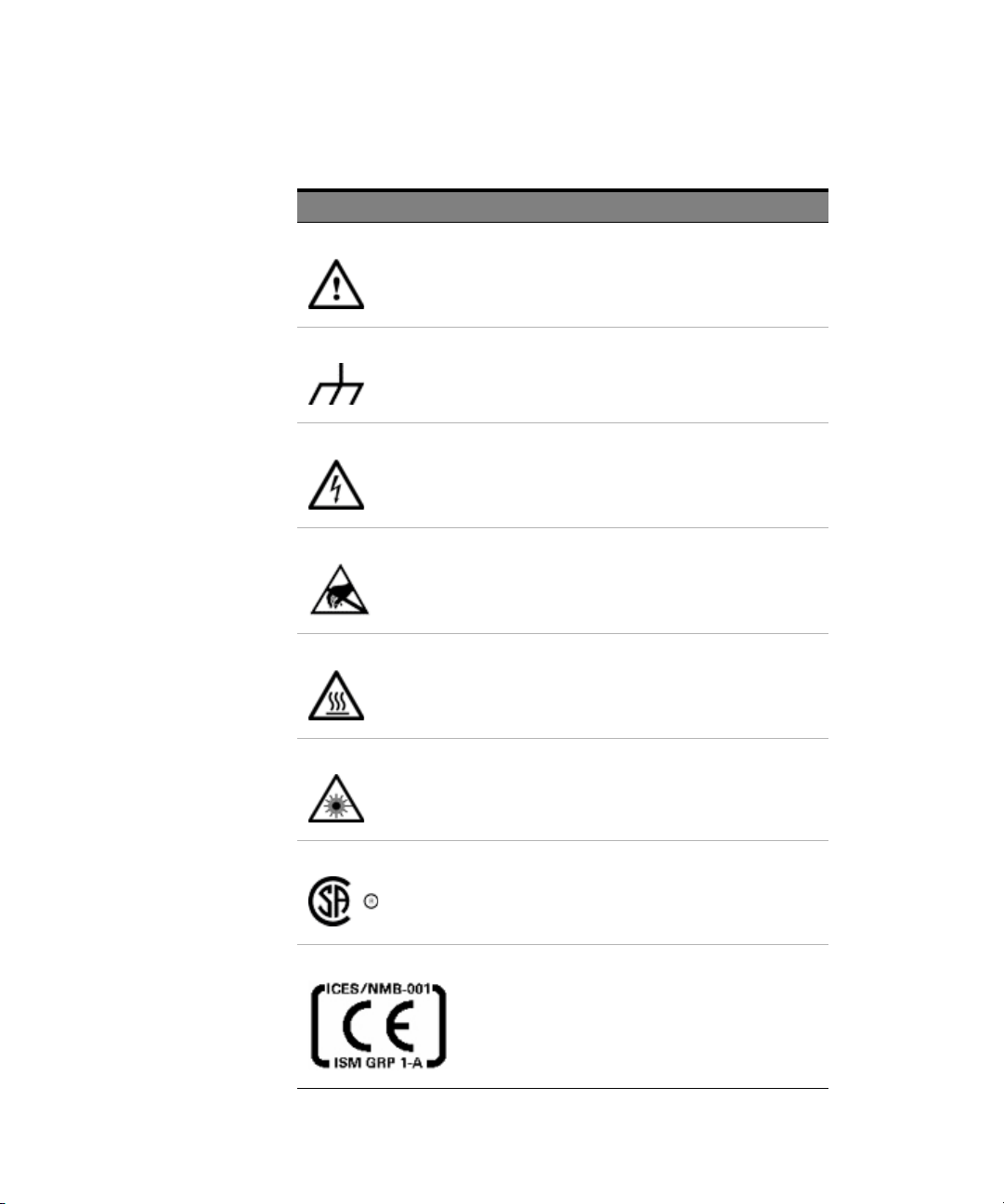
Safety Symbols
Table 1 Safety Symbol
Symbol Description
Indicates warning or caution. If you see this symbol on a
product, you must refer to the manuals for specific
Warning or Caution information to avoid personal injury
or damage to the product.
Frame or chassis ground terminal. Typically connects to
the equipment’s metal frame.
Indicates hazardous voltages and potential for electrical
shock.
Indicates that antistatic precautions should be taken.
Indicates hot surface. Please do not touch.
Indicates laser radiation turned on.
CSA is the Canadian certification mark to demonstrate
compliance with the Safety requirements.
CE compliance marking to the EU Safety and EMC
Directives.
ISM GRP-1A classification according to the
international EMC standard.
ICES/NMB-001 compliance marking to the Canadian
EMC standard.
4 Keysight M8000 Series of BER Test Solutions User Guide
Page 5

Compliance and Environmental Information
Table 2 Compliance and Environmental Information
Safety Symbol Description
This product complies with WEEE Directive (2002/96/EC) marking requirements.
The affixed label indicates that you must not discard this electrical/electronic
product in domestic household waste.
Product Category: With reference to the equipment types in WEEE Directive Annex I,
this product is classed as a “Monitoring and Control instrumentation” product.
Do not dispose in domestic household waste.
To return unwanted products, contact your local Keysight office, or see
http://about.keysight.com/en/companyinfo/environment/takeback.shtml for more
information.
Keysight M8000 Series of BER Test Solutions User Guide 5
Page 6

About This Guide
Here is how the information in this document is organized.
Introduction
This chapter provides an overview of this manual.
Know Your Hardware
This chapter provides an information on the various modules of
M8020A/M8030A/M8040A, their setup and the provided accessories.
Exploring M8070A User Interface
This chapter describes the M8070A user interface and the functionality provided by its
common GUI elements.
Configuring Your System
This chapter describes how to configure the M8020A/M8030A/M8040A system using the
Module View, Group View and System View.
Setting up Generator
This chapter provides information on settings provided by the M8020A/M8030A/M8040A
Generator.
Setting up Analyzer
This chapter provides information on settings provided by the M8020A/M8030A/M8040A
Analyzer.
Setting up Patterns
This chapter describes the functionality provided by the M8070A Pattern Editor and
Sequence Editor.
Working with Measurements
This chapter describes the setup, execution, monitoring and results of the measurements
supported by M8070A system software.
Utilities
This chapter describes the utilities provided by the M8070A system software.
Licenses
This chapter provides information on the M8020A/M8030A/M8040A and M8070A
licenses and their installation procedure.
Appendix
This chapter provides information about basic troubleshooting and factory patterns.
6 Keysight M8000 Series of BER Test Solutions User Guide
Page 7

Contents
1 Introduction
Safety Summary 3
Compliance and Environmental Information 5
About This Guide 6
Overview 24
J-BERT M8020A high-performance BERT 24
M8030A Multi-Channel BERT 25
M8040A High-Performance BERT 26
Document History 28
Related Documents 29
Abbreviations used in this Document 29
2 Know Your Hardware
M8020A Overview 32
M9505A AXIe Chassis 33
AXIe Embedded System Module (USB ESM) 34
Host Computer 35
M8030A Overview 36
M9514A AXIe Chassis 37
AXIe System Module (ASM) 38
Keysight M9537A AXIe Embedded Controller Module 39
M8020A / M8030A Modules 40
J-BERT M8041A Generator-Analyzer-Clock Module 40
M8041A Front Panel Connector Inputs/Outputs 43
Keysight M8000 Series of BER Test Solutions User Guide 7
Page 8

Contents
J-BERT M8051A Generator-Analyzer 45
M8061A 32 Gb/s Multiplexer with De-emphasis Module 48
M8061A Front Panel Connector Inputs/Outputs 50
M8062A 32Gb/s Front-end for J-BERT M8020A High-Performance
BERT
M8062A Features 51
M8062A Module Components 52
M8062A Front Panel Pattern Generator Connectors 53
M8062A Front Panel Analyzer Connectors 54
51
M8020A Module Setup 55
Setting up a Single Channel System 55
Setting up a Multi-Channel System 55
M8030A Module Setup 57
M8030A Modules Arrangement Example 58
M8040A Overview 59
M8040A Modules 60
M8045A High-Performance BERT Pattern Generator-Clock Module 60
M8046A High-Performance BERT Analyzer Module 64
M8057A Pattern Generator Remote Head 66
M8040A Module Setup 69
AWG Modules Supported by M8070A System Software 70
M8195A 65 GSa/s Arbitrary Waveform Generator 70
M8196A 92 GSa/s Arbitrary Waveform Generator 71
Other Supported Hardware(s) 72
Keysight N1076A/N1077A DCA-M Clock Recovery 72
Keysight Real Time Oscilloscopes 73
Hardware Setup for M8046A and M8062A Modules 74
Limitations 75
ESD Protection 76
8 Keysight M8000 Series of BER Test Solutions User Guide
Page 9

3 Quick Tour with M8070A User Interface
Overview 82
Launching M8070A User Interface 83
Messages while launching M8070A GUI 83
Load Setting 85
Get Module Information 87
Exploring M8070A User Interface 89
Title Bar 89
Menu Bar 89
Main Window 109
Status Bar 110
Other GUI Features 115
Recall/Save Instrument State 122
Recall Instrument State 122
Save Instrument State 123
4 User Interface - M8070A Display Views
Contents
Overview 126
Module View 127
How to Launch Module View 127
Input and Output Ports 130
Show Module Information 136
Selecting Single/Multiple Ports 137
Parameters Window 137
Creating Groups in the Module View 155
System View 156
Using the Zoom Tool 157
Understanding the System View 158
System View with M8061A Integration 162
System View with M8062A Integration 169
M8040A System View 173
Keysight M8000 Series of BER Test Solutions User Guide 9
Page 10

Contents
Impairment Setup View 175
How to Access the Impairment Setup View 175
Features of the Impairment Setup View 176
Viewing Options in the Impairment Setup View 178
How to set parameters in Impairment Setup View 180
How to Use Filters 182
Group View 185
How to Launch Group View 185
Setup View 191
How to Access the Setup View 191
Understanding Setup View 192
GUI Elements Description 195
How to perform a basic measurement 197
Adjustable Intersymbol Interference 198
Using System View for ISI Configuration 198
How to Launch Adjustable ISI Window: 199
Toolbar 200
Adjustable ISI Graph 201
ISI Parameters 201
Intersymbol Interference (ISI) Setup 202
Controlling AWG(s) from M8070A User Interface 203
AWG(s) in Module View 203
M819xA Configuration 204
Configuring AWG(s) Parameters 207
Simultaneous Injection of CMSI and DMSI Using M819xA AWGs 209
AWG as External Level Interference (RI/SI) Source 211
System View with AWG(s) Integration 213
Signal Generation in AWG 214
Using AWG Frequency Response Calibration for Improved Signal
Performance
Selecting Line Coding 215
10 Keysight M8000 Series of BER Test Solutions User Guide
215
Page 11

Creating Patterns for AWG(s) 217
Sequence Settings for AWG(s) 217
Settings to Generate Data and Clock Signals in AWG 219
Jitter Setting in AWG(s) 219
Extended Sequencing Capabilities in AWGs 221
Basic Sequencing 221
Extended Sequencing 221
Block Settings 223
Event Configuration 225
SCPI Commands 225
Controlling N1076A/77A from M8070A 226
One Time Preparation 226
Using N1076A/77A from within M8070A 228
FlexDCA and N1076A/77A Documentation 230
Offline Usage 230
Controlling a Real-Time Oscilloscope from M8070A 233
Required preparation steps 234
Setting up a LAN controlled real-time oscilloscope for usage by
M8070A
Understanding BER measurement with the real-time oscilloscope 238
Real-time oscilloscope in Module View 241
Differences to a hardware based error detector 242
Best practices 243
Remote controlling the real-time oscilloscope based error
detector
235
244
Contents
5 Setting up Generator
Overview 250
M8020A/M8030A Generator Ports 251
M8040A Generator Ports 253
Understanding the Output Protection Circuit 254
Understanding the Output Level Parameters 255
Keysight M8000 Series of BER Test Solutions User Guide 11
Page 12

Contents
Why Incorrect Terminations Could Damage Your Device 258
AC Coupling and Bias Tees 258
Setting up Terminations 261
DC Check (Unbalanced/Balanced Termination) for M8040A 262
Adjust Output Levels (optional) 265
De-Emphasis Signal Generator 266
M8045A De-Emphasis 269
Setting Up Data Out Port Parameters 272
Setting up Output Timing 274
Line Coding 275
Bit Rate 277
When to Use an External Clock Source? 277
Bit Rate Range 277
Spread Spectrum Clocking 279
Setting the Bit Rate 280
External Clock Divider 281
External PLL Clock Divider and Multiplier 281
Trigger Output 282
FEC Error Insertion 284
Error Insertion 288
FEC Error Insertion 290
Interference 294
Common Mode Interference (CMI) 294
Differential Mode Interference (DMI) 295
Jitter Setup 296
High Frequency Jitter (HF Jitter) 296
Low Frequency Jitter (LF Jitter) 296
Global Jitter State On/Off Switch 296
How to Enable Global Jitter State 297
Set Jitter Configuration 297
12 Keysight M8000 Series of BER Test Solutions User Guide
Page 13

6 Setting up Analyzer
Overview 310
M8020A/M8030A/M8040A Analyzer Ports 311
Data In Port Termination 312
Why Can Wrong Terminations Damage Your Device? 312
Setting Up Termination 313
Clock Setup 318
How does Clock Data Recovery Work? 318
Phase Locked Loop 318
CDR Setup in M8020A/M8030A 320
CDR Setup for M8040A 321
Sampling Point Setup 323
How Does the Sampling Point Setup Work? 323
Auto Alignment 323
Threshold Center Alignment 324
Delay Center Alignment 325
Canceling Auto Align 326
Alignment BER Threshold 326
Sampling Point Setup Window 326
Contents
Equalization 332
Equalization in M8041A/M8051A Data In 332
Equalization in M8062A Data In 333
Equalization in M8046A Data In 334
Pattern Synchronization 344
Introduction to Pattern Synchronization 344
What Type of Synchronization Should You Use? 347
What is False Synchronization? 348
How Can You Tell if Your Synchronization is False? 349
How to Synchronize an Incoming Pattern 351
Keysight M8000 Series of BER Test Solutions User Guide 13
Page 14

Contents
Bit Recovery Mode 352
Understanding Bit Recovery Mode (BRM) 352
Setting up Bit Recovery Mode 353
Line Coding 354
Alignment Results 355
7 Setting up Patterns
Pattern Overview 358
Sequence Editor 359
Overview 359
When to Use a Sequence 359
How a Sequence is Defined 359
How to Launch a Sequence Editor 360
Toolbar 361
Creating New Sequence 362
Importing a Sequence 363
Exporting a Sequence 365
Creating a Loop 365
Loop Within Sequences 366
Modifying the Existing Sequences 366
Sequence Setting Window 367
Editing a Pattern in a Sequence Editor 387
Sharing Sequences 388
User-Defined Sequences 389
Sequence Block Display 389
Sequence Block Parameters 389
Select Pattern Dialog 390
Application Specific Patterns 393
OIF CEI 393
IEEE 802.3 393
14 Keysight M8000 Series of BER Test Solutions User Guide
Page 15

Pattern Editor 395
How to Launch Pattern Editor 395
Toolbar 396
Settings Window 412
Pattern Edit Pane 414
Bit Coding 419
8B/10B Coding 421
128B/130B Coding 423
128B/132B Coding 425
Pattern Capture 428
How to Launch Pattern Capture Window 428
Toolbar 429
Parameters Window 430
How to Capture a Pattern 431
Pattern Capture Pane 432
Saving a Captured Pattern 433
Capture Results Pane 433
Interactive Link Training 435
PCI Express 3.0/4.0 Testing 435
Link Training PCIe 3.0 and PCIe 4.0 Parameters 440
Link Training for USB 3.0 and USB 3.1 443
Contents
Using M8062A Data Out Squelch Feature 455
Limitations 455
Hardware Requirements 455
Hardware Setup 455
Software Usage 455
8 Working with Measurements
Overview 460
Exploring Measurement User Interface 461
Launching the Measurement User Interface 461
Toolbar 462
Keysight M8000 Series of BER Test Solutions User Guide 15
Page 16

Contents
Status Indicator 463
Measurement History Window 463
Copy Measurement History Properties 464
Measurement Graph 464
Parameters Window 465
Calculated Results Pane 465
Error Ratio Measurement 467
Overview 467
Launching Error Ratio Measurement 467
Acquisition and Evaluation Parameters for Error Ratio 469
How to Run a Measurement 470
Error Ratio Measurement with PAM4 Symbols 471
How to Stop a Measurement 472
Measurement Graph 472
Test Times and Confidence Levels 473
Calculated Results 474
Error Ratio Measurement for a Group of Analyzers 477
Output Timing Measurement 479
Overview 479
Output Timing Characteristics 479
Jitter Characteristics 479
Example Results 479
Understanding the Jitter Calculation 480
Explanation of the Fast Total Jitter Measurement 483
Evaluation Parameters 485
Launching the Output Timing Measurement 487
Parameters Pane 488
How to Run Output Timing Measurement 489
How to Stop Output Timing Measurement 489
Measurement Graph 490
How an Output Timing Measurement Works 490
Calculated Results 491
Fast Total Jitter Measurement Results 493
Calculated Results for Fast Total Measurement 493
16 Keysight M8000 Series of BER Test Solutions User Guide
Page 17

Output Level Measurement 495
Overview 495
Launching the Output Level Measurement 495
Parameters Window 496
Changing the Measurement Setting 499
Available Views 499
How to Execute Output Level Measurement 500
How to Stop Output Level Measurement 500
Measurement Graph 500
How to Improve the Output Levels Display 502
How to Change the Output Levels Properties 502
Calculated Results 503
Jitter Tolerance Measurement 508
Overview 508
Understanding Jitter Tolerance 508
Types of Jitter 510
BER Setup 511
Graph Setup 511
Instrument Setup 512
Measurement Setup 512
Launching Jitter Tolerance Measurement 518
How to Run Jitter Tolerance Measurement 519
How to Stop/Abort Jitter Tolerance Measurement 519
Measurement Graph 520
Viewing the Jitter Tolerance Results 521
Saving Jitter Tolerance Measurement Results 522
Using the Jitter Tolerance Template Editor 522
Template Editor Toolbar 523
Template Editor Functions 524
Contents
Keysight M8000 Series of BER Test Solutions User Guide 17
Page 18

Contents
Eye Diagram Measurement 525
What is an Eye Diagram? 525
Methods of Representation of Eye Diagram 526
Eye Diagram Measurement Parameters 528
Launching the Eye Diagram Measurement 530
How to Start/Abort an Eye Diagram Measurement 530
How to Change the Default Settings 531
Calculated Eye Diagram Results 532
Parameter Sweep Plugin 534
Launching Parameter Sweep Plugin 534
Parameter Sweep Plugin Parameters 535
How to Run Parameter Sweep Measurement 537
How to Stop Parameter Sweep Measurement 537
Measurement Graph for Parameter Sweep 537
Measurement Data for Parameter Sweep 539
9 Utilities
Overview 542
Script Editor 543
Launching the Script Editor 544
Toolbar 545
Editor Pane 547
Output Pane 548
Console 549
Settings Window 549
Find and Replace 551
Creating a Script 552
Saving a Script 552
Importing a Script 552
Exporting a Script 553
Running a Script 553
Stopping a Script 554
Adding Duplicate Row/Selection in the Code 554
18 Keysight M8000 Series of BER Test Solutions User Guide
Page 19

DUT Control Interface 556
Launching the DUT Control Interfacer 556
Toolbar 558
Editor Pane 560
Output Pane 562
Console 562
Insert Code Window 563
Settings Window 563
Find and Replace 565
Creating a New Script 566
Open a Script 566
Saving a Script 566
Importing a Script 566
Exporting a Script 567
Running a Script 568
Stopping a Script 568
Adding Duplicate Row/Selection in the Code 568
Effects on M8070A GUI on Installing a DUT Control Script 569
Writing a Script Code for DUT Control Interface 571
Communication with the M8070A Instrument Layer 578
Contents
SCPI Editor 588
SCPI Basics 588
Executing SCPI Commands 592
SCPI Recorder 593
Self Test Utility 596
Launching the Self Test Utility 596
Toolbar 597
Self Test History 597
Self Test Results Window 598
Executing Self Test 598
Aborting Self Test 599
Saving Self Test Results 599
Deleting Self Test Results 600
Keysight M8000 Series of BER Test Solutions User Guide 19
Page 20

Contents
Licenses Window 601
Launching the Licenses Window 601
Settings Window 602
Display Tab 603
Channel Tab 603
Hints Tab 604
Logger Window 605
SCPI Server Information 606
Plug-in Manager 607
How to Launch Plug-in Manager 607
How to Install a Plug-in 608
How to Uninstall a Plug-in 609
How to Update a Plug-in 610
How to Access an Installed Plug-in Through M8070A User
Interface
612
10 Licenses
Overview 614
Supported Licenses 615
Node-Locked (Uncounted) Licenses 615
Floating Licenses 617
Module-Specific Licenses 617
M8020A/M8030A Licenses 618
M8070A System Software for M8000 Series of BER Test Solutions 618
M8041A - High-Performance BERT Module 618
M8041A - License Upgrades for M8041A High-Performance BERT
Module
M8051A - High-Performance BERT Module 622
M8051A - License Upgrades for M8051A High-Performance BERT
Module
20 Keysight M8000 Series of BER Test Solutions User Guide
620
623
Page 21

M8061A Multiplexer 2:1 with De-emphasis 624
M8062A 32Gb/s Front-end for J-BERT M8020A High-Performance
BERT
624
M8040A Licenses 626
M8045A Pattern generator and clock module, 32/64 Gbaud 626
M8046A Analyzer Module, 32/64 Gbaud 627
Keysight License Manager 628
Keysight License Service 629
Installing the Licenses 630
Software Requirements 630
Installing M8070A-OTP License (not required for M8020A-BU1 and
M8030A-BU1)
Installing Temporary License (Trial License) for the M8000 Series 630
Installing M8070A-ONP Floating/Networked License 631
Installing the FlexNet License Manager 633
Creating a New License Service using lmadmin.exe 642
Installing and Setting up Client PC Floating Licenses 643
Installing Module Licenses (not required for M8020A-BU1 and
M8030A-BU1)
Transporting an M8070A License 645
630
644
Contents
11 Appendix
Basic Troubleshooting 648
Updating software components 648
The chassis does not power up 648
Module is exceptionally hot 648
Contacting Keysight Technologies 648
M8070A Factory Patterns 649
Index
Keysight M8000 Series of BER Test Solutions User Guide 21
Page 22

Page 23

Keysight M8000 Series of BER Test Solutions
User Guide
1 Introduction
J-BERT M8020A high-performance BERT / 24
M8030A Multi-Channel BERT / 25
M8040A High-Performance BERT / 26
Document History / 28
Related Documents / 29
Abbreviations used in this Document / 29
Page 24

1 Introduction
Overview
J-BERT M8020A high-performance BERT
The Keysight J-BERT M8020A high-performance BERT enables fast,
accurate receiver characterization of single-and multi-lane devices
running up to 16 or 32 Gb/s.
With today’s highest level of integration, the M8020A streamlines your test
setup. In addition, automated in situ calibration of signal conditions
ensures accurate and repeatable measurements.
Figure 1 Typical base M8020A instrument configuration
Key Features
• Data rates up to 8.5 and 16 Gb/s expandable to 32 Gb/s
• 1 to 4 BERT channels in a 5-slot AXIe chassis
• Integrated and calibrated jitter injection: RJ, PJ1, PJ2, SJ, BUJ,
sinusoidal level interference (common-mode and differential-mode),
SSC (triangular and arbitrary, residual) and Clock/2
• 8 tap de-emphasis, positive and negative
• Integrated and adjustable Intersymbol Interference
• Interactive link training for PCI Express
• Built-in clock recovery and equalization
• All options and modules are upgradeable
24 Keysight M8000 Series of BER Test Solutions User Guide
Page 25

M8020A Applications
The J-BERT M8020A is designed for R&D and test engineers who
characterize and verify compliance of chips, devices, boards and systems
with serial I/O ports up to 16 Gb/s and 32 Gb/s in the consumer,
computer, mobile computing, data center and communications industry.
Introduction 1
The J-BERT M8020A can be used to test popular serial bus standards,
such as PCI Express
M-PHY, SD UHS-II, Fibre Channel, QPI, memory buses , backplanes,
repeaters, active optical cables, Thunderbolt, 10/40 GbE/SFP+/QSFP,
100 GbE/CFP2.
M8030A Multi-Channel BERT
The M8030A Multi-Channel BERT extents the J-BERT M8020A platform to
a real multi-channel BERT solution supporting up to 10 pattern generators
and 10 error detectors (EDs) to allow multi-channel application tests like,
PCIe and PON. Wherever multi-channel measurements are required in
order to speed up throughput or test under real application conditions, the
M8030A is a perfect solution.
®
, SATA/SAS, DisplayPort, USB Super Speed, MIPI
Figure 2 Typical base M8030A instrument configuration
Keysight M8000 Series of BER Test Solutions User Guide 25
Page 26

1 Introduction
Key Features
• Data rates up to 8.5 and 16 Gb/s
• 1 to 10 BERT pattern generator and analyzer and channels in a 14-slot
AXIe chassis
• Clock synchronization between all modules
• 8 tap de-emphasis, positive and negative
• Integrated and adjustable ISI
• Built-in clock recovery and equalization
M8030A Applications
The M8030A multi-channel BERT is designed for R&D and test engineers
who characterize and verify compliance for electronic chips, devices,
boards, systems with multiple I/O ports (up to 16 Gb/s) in various industry
segments dealing with basic consumer goods, computer devices,
communication equipments, etc. Typical applications are:
• PCIe multi-channel test
• PON applications
• XAUI and GAUI multi-lane test
M8040A High-Performance BERT
The Keysight Technologies M8040A is a highly integrated BERT for
physical layer characterization and compliance testing.
With support for pulse amplitude modulation 4-level (PAM4) and
non-return-to-zero (NRZ) signals, and symbol rates up to 64 Gbaud
(corresponds to 112 Gbit/s) it covers all flavors of the emerging 400 GbE
and CEI-56G standards.
The M8040A BERT´ s true error analysis provides repeatable and accurate
results, optimizing the performance margins of your devices.
Key Features
The M8040A provides the following features:
• Data rates from 2 to 32 and 64 Gbaud
• PAM4 and NRZ selectable from M8070A user interface
• Built-in 4 tap de-emphasis to compensate loss
• Integrated and calibrated jitter injection: RJ, PJ1, PJ2, SJ, BUJ, and
Clk/2 Jitter
26 Keysight M8000 Series of BER Test Solutions User Guide
Page 27

• Two pattern generator channels per module to emulate aggressor
• Linearity tests with adjustable PAM4 levels
• Short connections to the DUT with remote heads for the pattern
generator
• True PAM4 error detection in real-time for low BER levels
• Graphical user interface and remote control via M8000 system software
• Scalable and upgradeable with options and modules
• Clock recovery with N1076A and N1077A
M8040A Applications
The M8040A is designed for R&D and test engineers who characterize
chips, devices, transceiver modules and sub-components, boards and
systems with serial I/O ports operating with data rates up to 32 Gbaud and
64 Gbaud in the data center and communications industries.
The M8040A can be used for receiver (input) testing for many popular
interconnect standards, such as:
• 400 Gigabit Ethernet (IEEE 802.3bs)
• 200/100/50 Gigabit Ethernet
• OIF CEI - 56G (NRZ and PAM4 versions)
• 64G/112G Fibre Channel
• Infiniband-HDR
•CDAUI-8
• Proprietary interfaces for chip-to-chip, chip-to-module, backplanes,
repeaters, and active optical cables, operating up to 64 Gbaud.
Introduction 1
Figure 3 Typical M8040A instrument configuration
Keysight M8000 Series of BER Test Solutions User Guide 27
Page 28

1 Introduction
Document History
Table 3 Document History
Edition Description
Edition 1.0, June 2014 Edition 1.0 of the M8000 Series User Guide is in accordance to the
Edition 2.0, October 2014 Edition 2.0 of the M8000 Series User Guide is in accordance to the
Edition 3.0, March 2015 Edition 3.0 of the M8000 Series User Guide is in accordance to the
Edition 4.0, August 2015 Edition 4.0 of the M8000 Series User Guide is in accordance to the
Edition 4.1, September 2015 Edition 4.1 of the M8000 Series User Guide is in accordance to the
Edition 4.2, January 2016 Edition 4.2 of the M8000 Series User Guide is in accordance to the
Edition 5.0, February 2016 Edition 5.0 of the M8000 Series User Guide is in accordance to the
Edition 5.1, March 2016 Edition 5.1 of the M8000 Series User Guide is in accordance to the
Edition 6.0, July 2016 Edition 6.0 of the M8000 Series User Guide is in accordance to the
Edition 7.0, August 2016 Edition 7.0 of the M8000 Series User Guide is in accordance to the
Edition 8.0, December 2016 Edition 8.0 of the M8000 Series User Guide is in accordance to the
M8070A version 1.0.
M8070A version 1.5.
M8070A version 2.0.
M8070A version 2.5.
M8070A version 2.6.
M8070A version 2.7.
M8070A version 3.0.
M8070A version 3.1.
M8070A version 3.4 (PG release).
M8070A version 3.4 (ED release).
M8070A version 3.5.
Edition 9.0, June 2017 Edition 9.0 of the M8000 Series User Guide is in accordance to the
Edition 9.1, August 2017 Edition 9.1 of the M8000 Series User Guide is in accordance to the
Edition 10.0, October 2017 Edition 10.0 of the M8000 Series User Guide is in accordance to the
28 Keysight M8000 Series of BER Test Solutions User Guide
M8070A version 3.6.
M8070A version 3.7.
M8070A version 4.0.
Page 29

Edition Description
Introduction 1
Related Documents
Edition 11.0, December 2017 Edition 11.0 of the M8000 Series User Guide is in accordance to the
M8070A version 4.5.
Edition 12.0, June 2018 Edition 12.0 of the M8000 Series User Guide is in accordance to the
M8070A version 5.0.
Edition 13.0, July 2018 Edition 13.0 of the M8000 Series User Guide is in accordance to the
M8070A version 5.1.
Table 4 Related Documents
Document Part No. Document Title
M8000-91010 Tips for Preventing Damage
M8000-91020 M8020A Start Here Document
M8030-91010 M8030A Start Here Document
M8020-91010 M8000 Series BER Test Solutions Installation Guide
M8020-91020 M8020A/M8030A Getting Started Guide
M8020-91030 M8000 Series BER Test Solutions User Guide
M8020-91040 M8000 Series BER Test Solutions Programming Guide
M8070-91010 M8000 Series BER Test Solutions Plug-ins
M8040-91010 M8040A Start Here Document
M8040-91020 M8040A Getting Started Guide
Abbreviations used in this Document
Table 5 Abbreviations
Abbreviation Extended Form
AXIe AdvancedTCA Extensions for Instrumentation and Test
AWG Arbitrary Waveform Generator
BER Bit Error Ratio
Keysight M8000 Series of BER Test Solutions User Guide 29
Page 30

1 Introduction
Abbreviation Extended Form
CDR Clock Data Recovery
CTLE Continuous-Time Linear Equalizer
DUT Device Under Test
ESD Electrostatic Discharge
ESM Embedded System Module
GB Gigabyte
GUI Graphical User Interface
J-BERT Jitter-Bit Error Ratio Tester
LED Light-Emitting Diode
MB Megabyte
MIPI Mobile Industry Processor Interface
PC Personal Computer
PCIe Peripheral Component Interconnect Express
30 Keysight M8000 Series of BER Test Solutions User Guide
PLL Phase Locked Loop
PRBS Pseudorandom Binary Sequence
PXI PCI eXtensions for Instrumentation
R & D Research & Development
SAS Serial Attached SCSI
SATA Serial Advanced Technology Attachment
SCPI Standard Commands for Programmable Instruments
SMA SubMiniature Version A
SSC Spread Spectrum Clock
TCP Transmission Control Protocol
USB Universal Serial Bus
VCO Voltage Controlled Oscillator
Page 31

Keysight M8000 Series of BER Test Solutions
User Guide
2 Know Your Hardware
M8020A Overview / 32
M9505A AXIe Chassis / 33
Host Computer / 35
M8030A Overview / 36
M9514A AXIe Chassis / 37
M8020A / M8030A Modules / 40
M8020A Module Setup / 55
M8030A Module Setup / 57
M8040A Overview / 59
M8040A Modules / 60
M8040A Module Setup / 69
AWG Modules Supported by M8070A System Software / 70
Other Supported Hardware(s) / 72
Hardware Setup for M8046A and M8062A Modules / 74
ESD Protection / 76
Page 32

2 Know Your Hardware
NOTE
M8020A Overview
The Keysight’s J-BERT M8020A High-Performance BERT is a modular
instrument which supports the following modules:
• M8041A high-performance BERT generator-analyzer-clock 8/16 Gb/s.
• M8051A high-performance BERT generator-analyzer
8/16 Gb/s.
• M8061A multiplexer 2:1 with de-emphasis 32 Gb/s.
• M8062A 32Gb/s Front-end for J-BERT M8020A High-Performance
BERT
• In addition to above J-BERT modules, it also supports M8195A and
M8196A Arbitrary Waveform Generator modules. Details of these
modules can be found at www.keysight.com/find/m8195a and
www.keysight.com/find/m8196a
M8020A being a modular product includes different sets of modules which
are hosted in an AXI chassis. Each module and its features have their own
license. You need to install these options in your instrument in order to use
the modules or features. For details, refer to the chapter Licenses on
page 613. However, if you have ordered M8020A-BU1, no license is
required.
The M8041A module must be installed in slots 1 through 3 in the AXIe
chassis unless the M9536A AXIe Embedded Controller is installed. The
following configurations are possible in an M9505A 5-slot chassis:
• 1 or 2-channel, 16 Gb/s - (1) M8041A
• 3 or 4-channel, 16 Gb/s - (1) M8041A + (1) M8051A
• 1-channel, 32 Gb/s (Pattern Generator only) - (1) M8041A +
(1) M8061A
• 1-channel, 32 Gb/s (Pattern Generator only or full BERT) - (1)
M8041A + (1) M8062A
• M8195A/M8196A module can more or less arbitrarily be added into the
5 slot module
Additionally, the M8061A, M8062A and M8195A/M8196A modules can be
installed and operated in a 2 slot frame.
In case an AWG module (M8195A/M8196A) is used in a combined system
with M8020A modules, ensure that the AWG modules should be always be
mounted in a slot number higher that M8020A modules in the AXIe
chassis. In other words, an AWG module always has to mounted last in the
chassis.
32 Keysight M8000 Series of BER Test Solutions User Guide
Page 33

M9505A AXIe Chassis
NOTE
Know Your Hardware 2
For details on the features and hardware components of each of the
above-mentioned modules, refer to M8020A / M8030A Modules on
page 40.
The M9505A AXIe Chassis is a modular instrument chassis that supports
complex and high density testing. The chassis provides slots for installing
multiple AXIe based instrument modules such as the M8041A, M8051A,
M8061A and M8062A modules. Besides providing a frame for the
installation of these instrument modules, the M9505A AXIe Chassis also
provides power, a cooling system, a PCIe Gen2 local data bus, a Gigabit
LAN interconnect, and a cabled USB (USB option required) and PCIe
connection for external host computer connectivity.
The following model of the M9505A AXIe Chassis supports the M8020A
modules:
• M9505A - a 5-Slot AXIe chassis
The USB connection is recommended when using a laptop or desktop PC
as an external controller. The PCIe connection is recommended for use
with a desktop PC as an external controller only.
Refer to the Keysight M9505A AXIe Chassis Startup Guide to get detailed
information about the AXIe chassis.
Keysight M8000 Series of BER Test Solutions User Guide 33
Page 34

2 Know Your Hardware
AXIe Embedded System Module (USB ESM)
The bottom slot of the AXIe chassis is reserved for the Embedded System
Module (ESM) which is factory-installed. The ESM has a USB 2.0 interface
as well as a PCIe x8, Gen1 and Gen2 compliant interface to connect an
external host computer to the chassis. The following figure shows the PCIe
Port and USB Port in ESM.
The ESM:
• runs the chassis embedded operating system which manages all
internal tasks and communications.
• tracks inserted modules and manages power requirements.
• monitors chassis temperature and controls variable-speed chassis fans.
• monitors module sensors and reports component failures to a system
log.
• acts as a Gigabit Ethernet switch; forwards frames along the backplane.
• connects an external host computer to the chassis.
• synchronizes timing across all modules through the Keysight Trigger
Bus, using an internal or external clock source.
• LAN connector on AXIe ESM is not used. Only use LAN connection on
the host computer.
• Either the PCIe (desktop only) or USB (desktop or laptop) port can be
used in this ESM but not both simultaneously. When you use the PCIe
port, the USB port is automatically disabled until the PCIe port is no
longer in use.
34 Keysight M8000 Series of BER Test Solutions User Guide
Page 35

Host Computer
Know Your Hardware 2
A host computer is used to:
• host all the software components of the instrument modules needed to
control, configure, and use the modules.
• communicate with the ESM of the M9505A AXIe Chassis to allow you to
monitor and control the chassis.
A host computer can be:
• the M9537A AXIe Embedded Controller module.
• a laptop with a USB port or with PCIe port.
• a desktop PC with a USB port or x8 or wider PCIe slot for the cabled
PCIe adapter card.
Keysight M9537A AXIe Embedded Controller Module
The M9537A AXIe Embedded Controller is a one slot module that you can
install in the M9505A AXIe Chassis like any other instrument module. This
module acts as a host computer when installed in the M9505A AXIe
Chassis. It is always installed in slot 1 of the M9505A AXIe Chassis.
The following figure displays this module.
Keysight M8000 Series of BER Test Solutions User Guide 35
Page 36

2 Know Your Hardware
M8030A Overview
The M8030A is a modular instrument which supports the following
modules.
• M8041A high-performance BERT generator-analyzer-clock 8/16 Gb/s
• M8051A high-performance BERT generator-analyzer 8/16 Gb/s
• M8092A Multi-channel synchronization module
The modules must be installed in the M9514A AXIe 14-slot chassis in the
following way:
Table 6 M8030A Modules Arrangement
Slot Number Module
# 1 M8030A-BU1 AXIe embedded controller. For M8030A-BU2 this slot is empty
# 2, 3 & 4 M8041A module
# 5 & 6 M8051A module
# 7 M9521A AXIe system module, always included in M8030A-BU1 or
and covered with filler front-plane
M8030A-BU2, must be in this slot
# 8 & 9 M8051A module
# 10 & 11 M8051A module
# 12 & 13 M8051A module
# 14 M8192A multi-channel synchronization module, always required in this slot
For details on the features and hardware components of each of the above
mentioned modules, refer to M8020A and M8030A Getting Started Guide.
36 Keysight M8000 Series of BER Test Solutions User Guide
Page 37

M9514A AXIe Chassis
NOTE
NOTE
Know Your Hardware 2
The Keysight M9514A AXIe 14-slot chassis (one slot for the AXIe System
Module plus 13 instrument module slots) is a modular instrument chassis
fully compatible with the AXIe 1.0 Hardware specifications. It allows
multiple application-specific instrument modules to share a common
chassis frame, power supply, cooling system, PCI Express (PCIe) Gen 2
data bus, Gigabit LAN hub, local bus for module-to-module signaling, and
host PC connections.
Multiple chassis may be interconnected for scalability. The chassis
provides 13 general purpose peripheral slots that accept 1U AXIe
instrument modules. Each module slot has a Gen 2 x4 link (maximum of
2 GB/s data rate per module) to the chassis primary data ‘fabric’ hub—a x8
PCIe switch and data bus.
The chassis requires a full module height AXIe System Module (ASM) such
as the Keysight M9521A, to manage chassis functions.
.
The USB connection is recommended when using a laptop or desktop PC
as an external controller. The PCIe connection is recommended for use
with a desktop PC as an external controller only.
PCIe connectivity between the M9514A AXIe Chassis and an external
desktop PC controller is recommended when full channel plus large
patterns need to be downloaded.
Refer to the Keysight M9514A AXIe Chassis Startup Guide to get detailed
information about the AXIe chassis.
Keysight M8000 Series of BER Test Solutions User Guide 37
Page 38

2 Know Your Hardware
AXIe System Module (ASM)
The M9521A AXIe System Module (ASM) is installed in the system slot of
the M9514A (slot 7). It provides the system communication and
synchronization functions required in an AXIe chassis including:
• Trigger bus and clock routing.
• Managing clocks, including internal or external reference sources.
• Gigabit LAN switching with front panel RJ45 LAN connections.
• AXIe Fabric 1 switching (Gen 2 x4 lanes to each module slot).
38 Keysight M8000 Series of BER Test Solutions User Guide
Page 39

Keysight M9537A AXIe Embedded Controller Module
The M9537A AXIe Embedded Controller is a one slot module that you can
install in the M9505A/M9514A AXIe Chassis like any other instrument
module. This module acts as a host computer when installed in the
M9505A/M9514A AXIe Chassis. It is always installed in slot 1 of the
M9505A AXIe Chassis. It may be installed in any slot of the M9514A AXIe
chassis except for Slot 7 which is reserved for the ASM. However, to
eliminate interference with the local bus used for E-Keying (if your AXIe
modules use E-Keying), you should install the controller in one of the
outside slots; e.g., 1 or 14 first, then 2 or 13, etc.
The following figure displays this module:
Know Your Hardware 2
The ESM:
• runs the chassis embedded operating system which manages all
internal tasks and communications.
• tracks inserted modules and manages power requirements.
• monitors chassis temperature and controls variable- speed chassis
fans.
• monitors module sensors and reports component failures to a system
log.
• acts as a Gigabit Ethernet switch; forwards frames along the backplane.
• connects an external host computer to the chassis.
• synchronizes timing across all modules through the Keysight Trigger
Bus, using an internal or external clock source.
LAN connector on AXIe ESM is not used. Only use LAN connection on the
host computer.
Either the PCIe (desktop only) or USB (desktop or laptop) port can be used
in this ESM but not both simultaneously. When you use the PCIe port, the
USB port is automatically disabled until the PCIe port is no longer in use.
Keysight M8000 Series of BER Test Solutions User Guide 39
Page 40
2 Know Your Hardware
M8020A / M8030A Modules
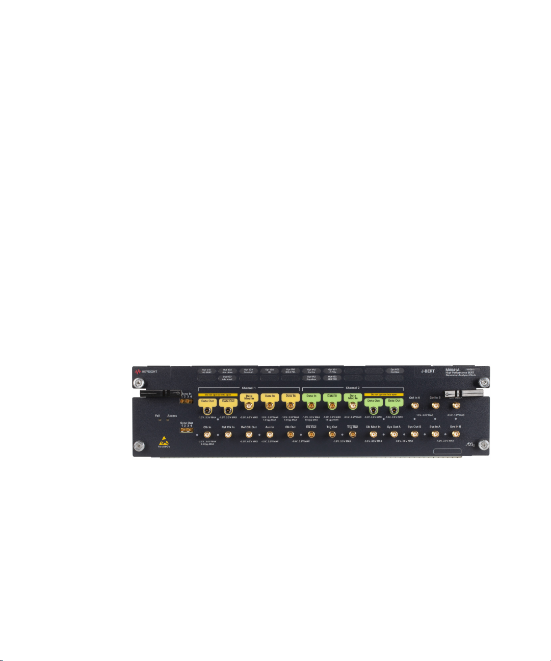
J-BERT M8041A Generator-Analyzer-Clock Module
The M8020A/M8030A modules are recognized by the model number and
name located on their front panel.
Each BERT module can be configured for 8 Gb/s or 16 Gb/s operation, as
generator-only or as full BERT. Some upgraded features/components of a
module are licensed and are only available when you purchase a license
for that option. The M8062A module supports 32 Gb/s and the M8195A as
a BERT module can support higher speeds than 16 Gb/s. The M8195A
cannot be used as a full BERT. It has no analyzer.
The following sections describe each of the M8020A/M8030A instrument
modules in detail.
The J-BERT M8041A is a BERT module that can be installed into an
Keysight M9505A 5-slot AXIe chassis. This module occupies three slots.
The M8041A is a two channel bit error ratio tester with built-in clock and
data generator for performing compliance and characterization
measurements. The second channel requires a license.
M8041A Features
The M8041A module provides the following features:
• Two channel pattern generator (option 0G2) and two channel error
detector (option 0A2)
• Data rate from 256 Mb/s to 16.2 Gb/s (option G16 or C16) for pattern
generation and error detection
• Built in jitter injection (option 0G3)
40 Keysight M8000 Series of BER Test Solutions User Guide
Page 41

• Adjustable ISI offered for M8041A and M8051A (option 0G5), software
Retaining Screws
Module Insertion/
Extraction Handles
Channel 1 Data
Inputs/Outputs
Channel 2 Data
Inputs/Outputs
Control Inputs/
Output
System Inputs/
Outputs
Clock Inputs/
Outputs
Front Panel LEDs
Sync In/Out
2.0 and serial number >= DE55300500
• Built in 8 tap de-emphasis (option 0G4)
• Built in receiver equalization (CTLE, option 0A3)
• Built in reference clock multiplier for pattern generator (option 0G6)
• Simultaneous common mode and differential mode level interference
(option 0G7)
• Interactive link training (option 0S1, Software 1.5)
• Four universal control inputs with adjustable threshold
• Three universal control outputs with adjustable levels
• 2 Gb pattern memory per channel (requires software 1.5)
M8041A Module Components
The following figure displays the front panel of the M8041A module with its
various components labeled.
Know Your Hardware 2
Keysight M8000 Series of BER Test Solutions User Guide 41
Page 42

2 Know Your Hardware
Component Description
The M8041A module has the following components.
Table 7 Insertion/Extraction and Retaining
Retaining screws The screws on both ends of the module are used to retain the module tightly inside the M9505A AXIe
Module Insertion/Extraction
Handles
Connector Name Active when... Color
Fail power-up fault condition red
Access power-up ready state green
Data In x input is overloaded red
Data Out x output is overloaded red
Data Mod In x input is active green
Ctrl In A/Ctrl In B logic level is detected green
Ctrl Out A output is active green
Clk In signal is detected green
Ref Clk In signal is detected green
Ref Clk Out output is active green
Chassis slot once you have fully placed it inside the chassis. To remove the module, you first need to
loosen these screws ensuring that these screws disengage completely.
The handles on both sides of the module to insert or eject the module from the slot of the M9505A AXIe
Chassis.
Table 8 Front Panel LEDs
Aux In not used n/a
Clk Out output is active green
Trig Out output is active green
Clk Mod In input is active green
Sys Out A/Sys Out B output is active green
Sys Ctrl In A/Sys Ctrl In B logic level is detected green
42 Keysight M8000 Series of BER Test Solutions User Guide
Page 43

M8041A Front Panel Connector Inputs/Outputs
CAUTION
The inputs of the M8041A module are sensitive to static electricity.
Therefore, take necessary anti-static precautions, such as wearing a
grounded wrist strap, to minimize the possibility of electrostatic damage.
Table 9 Channel x Data Inputs/Outputs
Component Description
Data Out and /Data Out Differential data outputs (3.5 mm, female).
Data In and /Data In Differential data inputs (3.5 mm, female).
Data Mod In Accepts an external source for data out delay modulation (SMA, female).
Table 10 Clock Inputs/Outputs
Component Description
Know Your Hardware 2
Clk In External clock input in the range of 8.1 to 16.2 GHz. This input is used as a direct clock for all
Ref Clk In Reference clock input for applications that provide a host reference clock in the range of 10 MHz to
Ref Clk Out The reference clock output is used to provide a 10 MHz or 100 MHz reference clock to the DUT or
Clk Out and /Clk Out Differential clock output (3.5 mm, female).
Trig Out and /Trig Out This output is used to send a trigger signal to another connected device, such as an oscilloscope (3.5
Clk Mod In Input for delay modulation of the Trig Out and Clk Out channel. Both outputs are always affected
Keysight M8000 Series of BER Test Solutions User Guide 43
channels in forwarded clock applications (SMA, female).
16 GHz. The clock signal may be SSC modulated and is used as the reference for the system clock of
all Tx and Rx channels. A SSC tolerant PLL is used to multiply the reference clock to the system clock
(SMA, female).
other test equipment (SMA, female).
mm, female). It can also be used as a sub rate clock.
(SMA, female).
Page 44

2 Know Your Hardware
Table 11 Sync In/Sync Out
Component Description
Sync In This input is used to synchronize two or more modules to a common system clock. It is connected to
Sync Out This output is used to synchronize two or more modules to a common system clock. It is connected
Component Description
Sys Out A/Sys Out B System level control outputs used to signal events to the DUT or external instruments (SMA, female).
Sys In A/Sys In B System level control inputs used to generate sequencer events (SMA, female).
Component Description
Ctrl In A/Ctrl In B The module has two control inputs at the font panel each with the following selectable functionality
the Sync Out of the other module.
to the Sync In of the other module.
Table 12 System Inputs/Outputs
Table 13 Control Inputs/Output
(SMA, female):
Error Add Input
Every rising edge at the input generates a single error in the output data stream by flipping a single
bit. The maximum repetition rate is data rate divided by 4 times the vector size.
Output Blanking
If the input level is above the threshold level the pattern generator stops and only 0’s are sent on
data output. Normal operation resumes when the input level is below the threshold.
Electrical Idle
If the input level is above the threshold level the output amplifier enters electrical idle. Normal
operation resumes when the input level is below the threshold.
Gating Input
If a logical high is applied to the gating input the error detector will ignore the incoming bits during a
BER measurement. The ignored bit sequence is always a multiple of the vector size. For measuring
data in bursts of bits, rather than a continuous stream of bits, a special operating mode is used. This
mode is the burst sync mode. In this case, the signal at the gating input controls the synchronization
and the error counting for each burst.
Ctrl Out A The module has one control output at the front panel with the following functionality (SMA, female):
44 Keysight M8000 Series of BER Test Solutions User Guide
Error Output
This signal can be used to trigger an external instrument to help in error analysis. If an error occurs,
a single RZ pulse is generated. Continuous errors will result in a clock signal.
Page 45

J-BERT M8051A Generator-Analyzer
Retaining Screws
Module Insertion/
Extraction Handles
Channel 1 Data
Inputs/Outputs
Channel 2 Data
Inputs/Outputs
Control Inputs/
Output
Front Panel LEDs
Sync In
Know Your Hardware 2
The J-BERT M8051A
the M9505A 5-slot AXIe Chassis. This module occupies two slots and
requires the M8041A module for proper operation.
The M8051A is a two channel Generator and two channel Analyzer for
performing compliance and characterization measurements.
M8051A Features
The main M8051A features are the same as the M8041A features. For
details, refer to J-BERT M8041A Generator-Analyzer-Clock Module on
page 40.
M8051A Module Components
The following figure displays the front panel of the M8051A module with its
various components labeled.
is an instrument module that can be installed into
Keysight M8000 Series of BER Test Solutions User Guide 45
Page 46

2 Know Your Hardware
CAUTION
Component Description
The M8051A module has the following components.
Table 14 Insertion/Extraction and Retaining
Retaining screws The screws on both ends of the module are used to retain the module tightly inside the M9505A AXIe
Module Insertion/Extraction Handles The handles on both sides of the module to insert or eject the module from the slot of the M9505A AXIe
Connector Name Active when... Color
Fail power-up fault condition red
Access power-up ready state green
Data In x input is overloaded red
Data Out x output is overloaded red
Data Mod In x input is active green
Ctrl In A/Ctrl In B logic level is detected green
Chassis slot once you have fully placed it inside the chassis. To remove the module, you first need to
loosen these screws ensuring that these screws disengage completely.
Chassis.
Table 15 Front Panel LEDs
M8051A Front Panel Connector Inputs/Outputs
46 Keysight M8000 Series of BER Test Solutions User Guide
The inputs of the M8051A module are sensitive to static electricity.
Therefore, take necessary anti-static precautions, such as wearing a
grounded wrist strap, to minimize the possibility of electrostatic damage.
Page 47

Table 16 Channel x Data Inputs/Outputs
Component Description
Data Out and /Data Out Differential data outputs (3.5 mm, female).
Data In and /Data In Differential data inputs (3.5 mm, female).
Data Mod In Accepts an external source for data out delay modulation (SMA, female).
Table 17 Sync In
Component Description
Know Your Hardware 2
Sync In This input is used to synchronize two or more modules to a common system clock. It is connected to
the Sync Out of the other module or to the clock distribution module if more than two modules are
installed. The sync cable is required if M8051A is connected with M8041A module.
Table 18 Control Inputs/Output
Component Description
Ctrl In A/Ctrl In B The module has two control inputs at the font panel each with the following selectable functionality
(SMA, female):
Error Add Input
Every rising edge at the input generates a single error in the output data stream by flipping a single
bit. The maximum repetition rate is data rate divided by 4 times the vector size.
Output Blanking
If the input level is above the threshold level the pattern generator stops and only 0’s are sent on
data output. Normal operation resumes when the input level is below the threshold.
Electrical Idle
If the input level is above the threshold level the output amplifier enters electrical idle. Normal
operation resumes when the input level is below the threshold.
Gating Input
If a logical high is applied to the gating input the error detector will ignore the incoming bits during a
BER measurement. The ignored bit sequence is always a multiple of the vector size. For measuring
data in bursts of bits, rather than a continuous stream of bits, a special operating mode is used. This
mode is the burst sync mode. In this case, the signal at the gating input controls the synchronization
and the error counting for each burst.
Ctrl Out A The module has one control output at the front panel with the following functionality (SMA, female):
Error Output
This signal can be used to trigger an external instrument to help in error analysis. If an error occurs,
a single RZ pulse is generated with the width of half a vector length. Continuous errors will result in
a clock signal.
Keysight M8000 Series of BER Test Solutions User Guide 47
Page 48

2 Know Your Hardware
M8061A 32 Gb/s Multiplexer with De-emphasis Module
The M8061A
M9502A 2-slot or M9505A 5-slot AXIe Chassis. This module occupies two
slots.
The M8061A is used to characterize serial interfaces of up to 32 Gb/s. The
M8061A provides four calibrated de-emphasis taps, which can be
extended to eight taps, built-in superposition of level interference, and
Clock/2 jitter injection.
M8061A Features
• Expands data rate of M8041A and M8051A generators up to 32 Gb/s
enabling accurate and complete receiver stress testing
• Integrated and calibrated 4-tap de-emphasis, expandable to 8 taps
• Internal superposition of interference for common mode and differential
mode
• Transparent to jitter generated by the J-BERT M8020A, Clock/2 jitter
can be added
• Supports electrical idle
• Control from J-BERT M8020A user interface via USB.
is an instrument module that can be installed into the
M8061A Module Components
The following figure displays the front panel of the M8061A module with its
various components labeled.
48 Keysight M8000 Series of BER Test Solutions User Guide
Page 49

The M8061A module has the following components.
Table 19 Insertion/Extraction and Retaining
Component Description
Know Your Hardware 2
Retaining screws The screws on both ends of the module are used to retain the module tightly inside the M9505A AXIe
Chassis slot once you have fully placed it inside the chassis. To remove the module, you first need to
loosen these screws ensuring that these screws disengage completely.
Module Insertion/Extraction Handles The handles on both sides of the module to insert or eject the module from the slot of the M9505A AXIe
Chassis.
Table 20 Front Panel LEDs
Connector Name Active when... Color
Fail power-up fault condition red
Access power-up ready state green
Keysight M8000 Series of BER Test Solutions User Guide 49
Page 50

2 Know Your Hardware
CAUTION
M8061A Front Panel Connector Inputs/Outputs
The inputs of the M8061A module are sensitive to static electricity.
Therefore, take necessary anti-static precautions, such as wearing a
grounded wrist strap, to minimize the possibility of electrostatic damage.
Table 21 Electrical Idle Input
Component Description
Electrical Idle In This input is used to enable/disable the output signal by an external control signal. If the input level
Component Description
Clk Out Reference clock output used in clean clock mode to provide the synthesizer signal to the J-BERT
Clk In Reference clock input used in clean clock mode, the synthesizer should be connected to this port
Aux Clk In External clock input in the range of 150 MHz to 14.2 GHz. This input is used with the J-BERT’s
Component Description
DMI In Differential mode interference input independent of ground (SMA, female).
CMI In Common mode interference input relative to ground (SMA, female).
Component Description
is above the threshold level the module enters electrical idle. Normal operation resumes when the
input level is below the threshold (SMA, female).
Table 22 Clock Inputs/Output
without external splitter (3.5 mm, female).
(3.5 mm, female).
internal clock. In presence of jitter, this provides the same jitter as the data outputs (3.5 mm,
female).
Table 23 DMI/CMI Inputs
Table 24 Data Inputs/Outputs
Data Out and /Data Out Differential or single-ended data output (2.4 mm, female).
Data In x Single-ended data input (3.5 mm, female).
50 Keysight M8000 Series of BER Test Solutions User Guide
Page 51

M8062A 32Gb/s Front-end for J-BERT M8020A High-Performance BERT
NOTE
NOTE
The M8062A extends the data rate of the J-BERT M8020A Bit Error Ratio
Tester to the speeds required for testing devices with lane rates in the
25-28 Gb/s range. When combined with a two channel M8041A, the
system provides data pattern generation and full-rate error analysis for
users and systems with lane rates up to 32.4 Gb/s.
M8062A Features
• Extends maximum data rate of J-BERT M8020A up to 32.4 Gb/s
• Seamless control of pattern generator and error analyzer
• Integrated 8-tap de-emphasis
• Built in ISI generator for channel emulation
• Analyzer equalization eliminates errors resulting from closed eyes in
loop back path
• Built in CDR for data rates up to 32 Gb/s
Know Your Hardware 2
The CDR license (M8062A-0A4) is required to enable the CDR feature.
M8062A modules with serial numbers < MY55400300 may also require a
hardware upgrade in order to enable this feature.
Refer to the Online Help installed and integrated into the M8070A
software to learn about how to use this module.
Phase-matched cables must be used when connecting the M8041A data
and clock outputs to the M8062A data and clock inputs. The provided
cable set, Keysight M8062-61643, meets this requirement.
Keysight M8000 Series of BER Test Solutions User Guide 51
Page 52

2 Know Your Hardware
Front Panel LEDs
Sync In
Retaining Screws
Clean Clk Out
M8062A Front
Panel Error
Analyzer Connectors
M8062A Front
Panel Pattern
Generator
Connectors
CAUTION
M8062A Module Components
The following figure displays the front panel of the M8062A module with its
various components labeled.
The M8062A module has the following components.
Table 25 Insertion/Extraction and Retaining
Component Description
Retaining screws The screws on both ends of the module are used to retain the module tightly inside the M9505A AXIe
Chassis slot once you have fully placed it inside the chassis. To remove the module, you first need to
loosen these screws ensuring that these screws disengage completely.
Module Insertion/Extraction Handles The handles on both sides of the module to insert or eject the module from the slot of the M9505A AXIe
Connector Name Active when... Color
Fail power-up fault condition red
Access power-up ready state green
52 Keysight M8000 Series of BER Test Solutions User Guide
Chassis.
Table 26 Front Panel LEDs
The inputs and outputs of the M8062A module are sensitive to static
electricity. Therefore, take necessary anti-static precautions, such as
wearing a grounded wrist strap, to minimize the possibility of
electrostatic damage.
Page 53

Connector Name Description
Know Your Hardware 2
Table 27 Sync In/Clean Clk Out
Sync In This input is used to synchronize two or more modules to a common system clock. It is connected to the Sync
Out of the other module. The sync cable is required if M8062A is connected with M8041A module.
Clean Clk Out Half-rate, or divided, clock output with no applied jitter.
M8062A Front Panel Pattern Generator Connectors
Table 28 Electrical Idle Input
Component Description
Electrical Idle In This input is used to enable/disable the output signal by an external control signal. If the input level is above the
threshold level the module enters electrical idle. Normal operation resumes when the input level is below the
threshold (SMA, female).
Table 29 Pattern Generator Clock Inputs/Output
Component Description
Clk Out Half-rate Pattern Generator clock output. Carries the same jitter as the full-rate data output.
Clk In Pattern Generator clock input (half-rate). Connect to clock output of M8041A.
Aux Clk In Alternate Pattern Generator clock input (half-rate). Typically unused.
Table 30 DMI/CMI Inputs
Component Description
DMI In Differential Mode Interference input. Applies a single-ended, external interference source differentially to the
CMI In Common Mode Interference input. Applies a single-ended, external interference source to both the normal and
Keysight M8000 Series of BER Test Solutions User Guide 53
data output (SMA, female).
complement data output signals (SMA, female).
Page 54

2 Know Your Hardware
Ω
Ω
Component Description
Table 31 Pattern Generator Data Inputs/Outputs
Data Out and /Data Out Differential or single-ended, full-rate data output to the device under test. Unused outputs must be
Data In 1 and Data In 2 Single-ended, half-rate data inputs from the M8041A module (3.5 mm, female).
terminated into 50 . (2.4 mm, female).
M8062A Front Panel Analyzer Connectors
Table 32 Error Analyzer Data Inputs/Outputs
Component Description
Data In and /Data In Differential or single-ended, full-rate data input from the device under test. Unused input should be terminated
Data Out 1 and Data Out 2 Single-ended, half-rate data outputs to the M8041A module (3.5 mm, female).
into 50 . (2.4 mm, female). These ports are AC coupled.
Table 33 Error Analyzer Clock Inputs/Output
Component Description
Clk Out Half-rate Error Analyzer clock output, synchronous with analyzer sampling.
Clk In Half-rate, Error Analyzer clock input. Allows external clocking of the Error Analyzer.
54 Keysight M8000 Series of BER Test Solutions User Guide
Page 55

M8020A Module Setup
Setting up a Single Channel System
Setting up a Multi-Channel System
Know Your Hardware 2
M8020A being a modular product includes different sets of modules which
are hosted in an AXI chassis. It comprises of exactly one M8041A
generator-analyzer-clock module and optionally one additional M8051A
generator-analyzer module. The M8041A generator-analyzer-clock
module is a true superset of the M8051A generator-analyzer module.
The single channel system is the smallest configuration consisting of one
M8041A generator-analyzer-clock module within a 5-slot frame. You can
upgrade it to a 2 channel system by adding the two channel options
(second channel generator and second channel analyzer).
The multi-channel system is comprised of exactly one clock / data module
and one or more data channels mounted in an AXIe frame.
The multi-channel system can be:
2-Channel System
A two-channel system consists of one clock/data module.
The following figure illustrates a two-channel system.
Keysight M8000 Series of BER Test Solutions User Guide 55
Page 56

2 Know Your Hardware
4-Channel System
A four-channel system consists of one clock module and one data
modules.
The following figure illustrates a four-channel system.
56 Keysight M8000 Series of BER Test Solutions User Guide
For more details on how to establish connections between the M8020A
modules, refer to the M8020A/M8030A Installation Guide.
Page 57

M8030A Module Setup
Know Your Hardware 2
The M8030A is a modular test solution which can be tailored to your
specific needs from two channels with one M8041A to up to 10 channels.
The modules must be installed in the M9514A AXIe 14-slot chassis as
described in Tab le 34 on page -57:
Table 34 M8030A Modules Configuration
Slot Number Module
# 1 M8030A-BU1 AXIe embedded controller.
# 2, 3 & 4 M8041A module
# 5 & 6 M8051A module
# 7 M9521A AXIe system module
# 8 & 9 M8051A module
# 10 & 11 M8051A module
# 12 & 13 M8051A module
# 14 M8192A multi-channel synchronization module
Keysight M8000 Series of BER Test Solutions User Guide 57
Page 58

2 Know Your Hardware
Slot#1Slot
#2
Slot
#3
Slot
#4
Slot
#5
Slot
#6
Slot
#7
Slot#8Slot
#9
Slot
#10
Slot
#11
Slot
#12
Slot
#13
Slot
#14
M9537A
AXIe
Embed-
ded
Controll-
er
M8041A J-BERT
High-Performance BERT
Module
M8051A J-BERT
High-Performance
BERT Module
M9521A
$;,H
6\VWHP
0RGXOH
M8192A
AXIe
Clock
Sync
Module
M8051A J-BERT
High-Performance
BERT Module
M8051A J-BERT
High-Performance
BERT Module
M8051A J-BERT
High-Performance
BERT Module
M8030A Modules Arrangement Example
The following figure shows the M8030A modules arrangement in the
M9514A AXIe 14-slot chassis:
58 Keysight M8000 Series of BER Test Solutions User Guide
Page 59

M8040A Overview
NOTE
Know Your Hardware 2
The M8040A is a modular instrument which supports the following
modules:
• M8045A High-Performance BERT Pattern Generator-Clock
• M8046A High-Performance BERT Analyzer
• M8057A Pattern Generator Remote Head
M8040A being a modular product includes different sets of modules which
are hosted in an AXI chassis. Each module and its features have their own
license. You need to install these options in your instrument in order to use
the modules or features. For details, refer to the chapter Licenses on
page 613. However, if you have ordered M8040A-BU1, no license is
required.
For details on the features and hardware components of each of the above
mentioned modules, refer to M8040A Getting Started Guide.
In case an AWG module (M8195A/M8196A) is used in a combined system
with M8040A modules, ensure that the AWG modules should be always be
mounted in a slot number higher that M8040A modules in the AXIe
chassis. In other words, an AWG module always has to mounted last in the
chassis.
Keysight M8000 Series of BER Test Solutions User Guide 59
Page 60

2 Know Your Hardware
M8040A Modules
M8045A High-Performance BERT Pattern Generator-Clock Module
The M8045A module can be a one or two data channel system (a second
channel can be added with license). A one channel instrument has to be
returned to the factory for installing the second channel (hardware) and
license. It occupies three slots of the 5-slot M9505A AXIe chassis.
M8045A Features
• Up to two Pattern Generator channels per 3-slot-module
• Symbol rate 2 to 64 Gbaud
• NRZ and PAM4 format is software-selectable
• PAM4 up to 64 Gbaud
• Built in de-emphasis
• Built in and calibrated jitter generation
• External jitter modulation per channel
• Remote head to get close to the DUT
• Pattern memory, PRBS, pattern sequencing
• Sequencing control by external control signals
Refer to the Online Help installed and integrated into the M8070A
software to learn about how to use this module.
M8045A Module Components
The following figure displays the front panel of the M8045A module
(2 data channel system):
60 Keysight M8000 Series of BER Test Solutions User Guide
Page 61

The M8045A module has the following components.
Table 35 Insertion/Extraction and Retaining
Component Description
Know Your Hardware 2
Retaining screws The screws on both ends of the module are used to retain the module tightly
Module Insertion/Extraction
Handles
Table 36 Front Panel LEDs
Connector Name Active when... Color
Fail power-up fault condition red
Access power-up ready state green
Data Mod In 1/2 signal is detected green
Clk Out 1/2 output is active green
Ctrl Out 1/2 output is active green
Ctrl In 1/2 logic level is detected green
P & N 1/2 output is active green
Clk In signal is detected green
Ref Clk In signal is detected green
inside the M9505A AXIe Chassis slot once you have fully placed it inside the
chassis. To remove the module, you first need to loosen these screws ensuring
that these screws disengage completely.
The handles on both sides of the module to insert or eject the module from the
slot of the M9505A AXIe Chassis.
Ref Clk Out Outputs a 10 and 100 MHz clock, 1 Vpp single ended
into 50 Ohm
Aux In not used n/a
Clk Out output is active green
Trig Out output is active green
Keysight M8000 Series of BER Test Solutions User Guide 61
green
Page 62

2 Know Your Hardware
CAUTION
Connector Name Active when... Color
Clk Mod In input is active green
Sys Out A/Sys Out B output is active green
Sys In A/Sys In B logic state is detected green
M8045A Front Panel Input/Output Ports
The inputs/outputs of the M8045A module are sensitive to static
electricity. Therefore, take necessary anti-static precautions, such as
wearing a grounded wrist strap, to minimize the possibility of
electrostatic damage.
Connector Name Description
Clk Out 1, 2 • Low Jitter (~150fs) Clk out. Baud-rate / 1,2,4,8,16
P and N P and N must be connected to M8057A remote head.
Remote Head 1, 2 Remote Head Control. This output provides power and control signals for the
Data Mod In 1, 2 This input is used for data out delay modulation by an external source.
62 Keysight M8000 Series of BER Test Solutions User Guide
Table 37 M8045A Front Panel Input/Output Ports
• Same Jitter as Data out or clean clk
• Typ 1.5 V pp
• Used for Analyzer as external clock
remote head amplifier
Page 63

Connector Name Description
Know Your Hardware 2
Ctrl In A, B The data module has 2 control inputs at the front panel. The functionality of
each individual input can be selected.
• Error Add Input
Every rising edge at the input generates a single error in the output stream
by flipping a single bit. The maximum repetition rate is data rate divided by 4
times the vector size.
• Output Blanking
If the input level is above the threshold level pattern generation stops and
only 0’s are sent on data out. Normal operation resumes when the input
level is below the threshold.
• Electrical Idle
If the input level is above the threshold level the output amplifier enters
electrical idle. Normal operation resumes when the input level is below the
threshold.
Ctrl Out A, B The data module has 2 control output at the front panel. The functionality of this
output can be selected.
• Error Output
This signal can be used to trigger an external instrument to help in error
analysis. If an error occurs a single RZ pulse is generated with the width of
half a vector length. Continuous errors will result in a clock signal.
Sync Out A, B This output is used to synchronize two or more modules to a common system
clock. It is connected to the SYNC IN of the other module or to the M8192A if
more than two modules are used.
Clk In Clock not used for M8045A.
Ref Clk In Reference clock input for applications that provide a host reference clock in the
range of 10 MHz … 16 GHz. It may be SSC modulated and is used as the
reference for the system clock of all TX and RX channels. A SSC tolerant PLL is
used to multiply the reference clock to the system clock.
Ref Clk Out The reference clock output is used to provide a 10 MHz or 100 MHz reference
Aux In Port not in use.
Clk Out Differential clock output.
Trig Out This output is used to send a trigger signal to another connected device, such as
Clk Mod In Input for delay modulation of TRIG OUT and CLK OUT channel, always affects
Sys In A, Sys In B These are control inputs at system level and can be used to generate events for
Sys Out A, Sys Out B These are control outputs at system level and can be used to signal events to
Keysight M8000 Series of BER Test Solutions User Guide 63
clock to the DUT or other test equipment.
an oscilloscope.
both outputs.
the sequencer. The granularity is the vector size.
the DUT or external instruments. The granularity is the vector size.
Page 64

2 Know Your Hardware
NOTE
M8046A High-Performance BERT Analyzer Module
The M8046A is an instrument module that can be installed into the
M9505A 5- slot AXIe chassis. This module occupies one slot.
The M8046A supports symbol rates up to 32.4 Gbaud, the default is NRZ
format.
The analyzer module can be used for error analysis in conjunction with the
M8045A pattern generator, the M8195A/M8196A Arbitrary Waveform
generators or as stand-alone.
With M8070A software version 5.0, the M8046A can also be used in
conjunction with M8041A + M8062A.
The three or four channel configuration requires a cable (provided with
the M8046A) that connects the M8045A Sync Out to the M8046A
Sync In to synchronize the two modules to a common system clock.
The M8046A Analyzer module can also be used with an external clock
coming from CR (e.g. N1076A) or Generator output (M8045A
channel 1/2 Clock Output or M8195A/M8196A Data Output).
64 Keysight M8000 Series of BER Test Solutions User Guide
M8046A Features
• Symbol rates 2 to 32.4 Gbaud
• One channel per 1-slot module
• 70 mV input sensitivity
• Supports NRZ and PAM4
• Built-in equalization
• Real-time bit error and symbol error analysis
M8046A Module Components
The following figure displays the front panel of the M8046A module with its
various components:
Page 65

The M8046A module has the following components.
Table 38 Insertion/Extraction and Retaining
Component Description
Know Your Hardware 2
Retaining screws The screws on both ends of the module are used to retain the module tightly
Module Insertion/Extraction
Handles
Table 39 Front Panel LEDs
Connector Name Active when... Color
Fail power-up fault condition red
Access power-up ready state green
Clk In on when output active and CLK detected green
Ctrl Out on when output active green
Ctrl In logic state is detected green
Data In data received green
inside the M9505A AXIe Chassis slot once you have fully placed it inside the
chassis. To remove the module, you first need to loosen these screws ensuring
that these screws disengage completely.
The handles on both sides of the module to insert or eject the module from the
slot of the M9505A AXIe Chassis.
Keysight M8000 Series of BER Test Solutions User Guide 65
Page 66

2 Know Your Hardware
CAUTION
NOTE
M8046A Front Panel Inputs/Outputs Ports
The inputs of the M8046A module are sensitive to static electricity.
Therefore, take necessary anti-static precautions, such as wearing a
grounded wrist strap, to minimize the possibility of electrostatic damage.
Table 40 M8046A Front Panel Inputs/Outputs Ports
Connector Name Description
Data In and /Data In Differential data inputs (3.5 mm, female)
Clk In Clock input to sample the incoming data. Full/half and quarter-rate clock.
Sync In This input is used to synchronize two or more modules to a common system
M8057A Pattern Generator Remote Head
Ctrl Out A Outputs a pulse in case of an error. Generates a pulse or static high/low if used
Ctrl In A This input can be used as sequence trigger or pattern capture event.
The M8057A remote head is an external box which must be connected to
each channel of M8045A module. The three cables are fixed on the back
side of M8057A which need to be connected to M8045A remote head, P
and N connectors. It helps in minimizing signal degradations caused by
lossy channels.
Single ended.
clock. It is connected to the Sync Out of the other module or to the clock
distribution module if more than two modules are installed. The sync cable is
required if M8046A is connected with M8045A Pattern Generator module. Not
needed if external clock is used.
from sequencer.
Please note that it is mandatory to connect M8057A remote head with
each channel of M8045A module. Operation without M8057A remote
head will not allow you to receive data.
66 Keysight M8000 Series of BER Test Solutions User Guide
Page 67
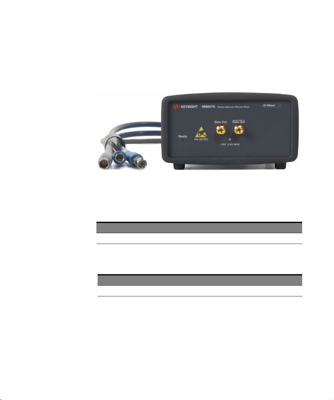
M8057A Remote Head Components
The following figure displays the front panel of the M8057A remote head
with its various components:
The M8057A remote head has the following components.
Know Your Hardware 2
Table 41 Front Panel LEDs
Connector Name Active when... Color
Ready remote head is operation green
Table 42 M8057A Front Panel Inputs/Outputs Ports
Connector Name Description
Data Out and /Data Out Connected to DUT
Keysight M8000 Series of BER Test Solutions User Guide 67
Page 68

2 Know Your Hardware
The following figure displays the back panel of the M8057A remote head
with its various components:
The back panel of M8057A remote head has cables which connects with
each channel of M8045A remote head controls (P and N). The length of
these cables are 85 cm.
Ensure that the chassis is NOT powered up or connected to a power
source while making connections to M8057A.
Also, make sure NOT to remove the M8057A connections when it is
powered on. However, if you wish to remove the M8057A connections,
ensure that the instrument is powered off.
68 Keysight M8000 Series of BER Test Solutions User Guide
Page 69

M8040A Module Setup
M8046A Module
M8045A Module
(2 Channels)
M8057A Remote Head
Know Your Hardware 2
The M8040A 64Gbaud BERT is based on individual modules that are
controlled by the M8070A software. The modules must be hosted in the
5-slot AXI chassis as described below:
• The M8045A module occupies three slots of the 5-slot M9505A AXIe
chassis. It must be installed in slots 1 through 3 in the AXIe chassis
unless the M9537A AXIe Embedded Controller is installed. The M9537A
AXIe Embedded Controller must be installed in slot 1.
• The M8046A module occupies a single slot of the 5-slot M9505A AXIe
chassis.
• The M8057A remote head is an external box which must be connected
to each channel of M8045A module. Three cables are fixed on the back
side of M8057A which need to be connected to M8045A remote head, P
and N connectors.
The following figure shows a typical setup of M8045A, M8046A and
M8057A.
Keysight M8000 Series of BER Test Solutions User Guide 69
Page 70

2 Know Your Hardware
NOTE
AWG Modules Supported by M8070A System Software
In addition to the BERT modules, the M8070A system software also
supports the following AWG modules:
• M8195A 65 GSa/s Arbitrary Waveform Generator - Currently supported
by M8070A Rev 3.5.104.4 or above and M8195A Rev 3.2.0.0 or above.
• M8196A 92 GSa/s Arbitrary Waveform Generator - Currently supported
by M8070A Rev 3.5.104.4 or above and M8196A Rev 2.0.39.0. or above.
In case an AWG module (M8195A/M8196A) is used in a combined system
with either M8020A or M8040A modules, ensure that the AWG modules
are always mounted in a slot number, higher that M8020A or M8040A
modules in the AXIe chassis. In other words, an AWG module always has
to be mounted, last in the chassis.
M8195A 65 GSa/s Arbitrary Waveform Generator
The Keysight M8195A is a 65 GSa/s Arbitrary Waveform Generator with
highest bandwidth and channel density. Flexible signal generation at up to
32 Gbaud. Clean and distorted signal to stress the device to the limits.
High speed AWG with up to 65 GSa/s sample rate and 20 GHz bandwidth
on up to 4 channels per module. The M8195A arbitrary waveform
generator offers an output amplitude of up to
2 Vpp (diff.) and adjustable DC offset.
The M8195A module has 4 channels and up to 5 modules can be inserted
in a 5 slot AXI chassis to provide the maximum of 20 channels. This is valid
for channels which are not synchronized across module boundaries. To
synchronize these modules, a sync module is added in the frame. Since the
sync module occupies a single slot, only 4 AWG modules can now be
added thereby providing a maximum of 16 channels in a frame.
The M8195A AWG gives you the versatility to create the signals you need
for digital applications, optical and electrical communication and
advanced research.
The basic functionality of the M8195A is controlled from a soft front panel
application running on the AXIe embedded controller or external PC or
laptop. However, the M8195A can also be integrated into the M8070A
system software for M8000 Series of BER test solutions.
Details of M8195A module can be found at
www.keysight.com/find/M8195A.
70 Keysight M8000 Series of BER Test Solutions User Guide
Page 71

M8196A 92 GSa/s Arbitrary Waveform Generator
The Keysight M8196A is a 92 GSa/s Arbitrary Waveform Generator with
highest bandwidth and channel density. It offers up to 4 x 512 kSa
waveform memory. It is a high speed AWG with up to 96 GSa/s sample
rate and 32 GHz bandwidth on up to 4 channels per module. The M8196A
arbitrary waveform generator offers an output amplitude of up to 2 Vpp
(diff.) and adjustable DC offset.
The M8196A provides high speed, precision, and flexibility which is ideally
suited for digital applications, optical, aerospace/defense, and electrical
communication.
The basic functionality of the M8196A is controlled from a soft front panel
application running on the AXIe embedded controller or external PC or
laptop. However, the M8196A can also be integrated into the M8070A
system software for M8000 Series of BER test solutions.
Details of M8196A module can be found at
www.keysight.com/find/M8196A.
Know Your Hardware 2
Keysight M8000 Series of BER Test Solutions User Guide 71
Page 72

2 Know Your Hardware
N1076A Electrical Clock Recovery
N1077A Optical/Electrical Clock Recovery
Other Supported Hardware(s)
Keysight N1076A/N1077A DCA-M Clock Recovery
The N1076A electrical clock recovery and N1077A electrical/optical clock
recovery provide necessary clock signals to trigger an 86100D,
N109x-series DCA-M oscilloscopes, or the error detector in a M8070A.
72 Keysight M8000 Series of BER Test Solutions User Guide
You can use an N1076/7A when:
• Access to appropriate clock signals from the Device Under Test (DUT) is
not possible. The clock is recovered from the data stream.
• The existing clock has excessive intrinsic jitter that prevents accurate
measurements. The N1076/7A can act as clean-up PLL for the clock.
• Input data is between 50 MBd and 16 GBd (32 GBd with option 232).
Detailed description of N1076A/N1077A can be found at:
www.keysight.com/find/N1076A
www.keysight.com/find/N1077A
Page 73

Keysight Real Time Oscilloscopes
NOTE
The M8070A system software (version 4.0 and above) supports certain
real-time oscilloscopes to measure BER of NRZ signals and BER as well as
SER of PAM4 signals. The real-time oscilloscope is completely controlled
from M8070A to capture a signal and convert into a pattern stream that is
then uploaded into the M8070A for comparison with an expected pattern
and provide BER/SER measurements.
Nevertheless, it is possible to stop measuring BER on the integrated
oscilloscope and therefore allow interactive tweaking of oscilloscope
settings before continuing the BER measurements.
Currently, the following oscilloscopes are supported:
• DSOZ634A
• DSAZ634A
• DSOX96204Q
• DSAX96204Q
• DSAZ594A
• DSOZ594A
Detailed description of the above oscilloscopes can be found at:
http://www.keysight.com/find/oscilloscopes
The following licenses are required on the oscilloscope:
• N5384A Serial Data Analysis (SDA)
• N8827A PAM4 Measurement (PM4)
• N5461A Equalization (DEQ)
Know Your Hardware 2
The minimum supported Infiniium version is 06.10.00616.
For details on how to control a real-time scope from M8070A, refer to the
section Controlling a Real-Time Oscilloscope from M8070A on page 233.
Keysight M8000 Series of BER Test Solutions User Guide 73
Page 74

2 Know Your Hardware
Hardware Setup for M8046A and M8062A Modules
The M8046A module and the M8062A module can be used in the same
setup. The following are the supported configurations:
1 Two M9505A 5-slot AXIe chassis controlled via USB
Chassis 1:
• Slot 1: M8041A
• Slot 4: M8062A
Chassis 2:
• Slot 1: M8046A
USB control ports of both chassis connected to the controlling PC
2 Two M9505A 5-slot AXIe chassis using an embedded controller
Chassis 1:
• Slot 1: M8041A
• Slot 4: M8062A
Chassis 2:
• Slot 1: Embedded Controller (M9536A or M9537A)
• Slot 2: M8046A
USB control port of chassis 1 is connected to a USB 2.0 port of the
embedded controller
3 M9514A 14-slot chassis controlled from external computer
• Slot 1: M8041A
• Slot 4: M8062A
• Slot 6: M8046A
• Slot 7: M9521A AXIe System Module
4 M9514A 14-slot chassis controlled from embedded controller
• Slot 1: Embedded Controller (M9536A or M9537A)
• Slot 2: M8041A
• Slot 5: M8062A
• Slot 7: M9521A AXIe System ModuleSlot 8: M8046A
The M8046A may be used with a N1076A external clock recovery.
74 Keysight M8000 Series of BER Test Solutions User Guide
Page 75

Limitations
Know Your Hardware 2
The following are the limitations while using the M8046A and M8062A
modules in the same setup:
• The M8046A does not support all sequencer word width settings of a
M8041A/M8062A combination.
• Even though M8041A/M8062A and M8046A support a common
sequencer word width of 1, they internally work with a different
granularity and therefore cannot be used in the same sequence. Instead
individual sequences need to be defined for M8062A Data Out, Data In
and M8046A.
• In order to run the M8062A Data Out and M8046A Data In at the same
symbol rate, the CLK IN frequency of M8046A needs to be specified
manually. To do this, disable 'Follow SYS CLK' under Clock and specify
CLK IN frequency and multiplier as required for the setup.
Keysight M8000 Series of BER Test Solutions User Guide 75
Page 76

2 Know Your Hardware
CAUTION
ESD Protection
Electrostatic discharge (ESD) can damage the circuits of the components
on M8020A/M8030A/M8040A modules (M8041A, M8051A, M8061A,
M8062A, M8045A, M8046A and M8057A). Avoid applying static
discharges to the front-panel connectors. Before connecting any coaxial
cable to the connectors, momentarily short the center and outer
conductors of the cable together. Avoid touching the front-panel
connectors without first touching the frame of the instrument. Be sure
the instrument and all connected devices (DUT, etc.) are properly
earth-grounded (to a common ground) to prevent buildup of static
charge and electrical over-stress. Take necessary anti-static
precautions, such as wearing a grounded wrist strap, to minimize the
possibility of electrostatic damage.
Electrostatic discharge (ESD) can damage or destroy electronic
components. All work on electronic assemblies should be performed at a
static-safe work station. The following list and figure shows an example of
a static-safe work station using two types of ESD protection. Purchase
acceptable ESD accessories from your local supplier.
• Conductive table-mat and wrist-strap combination.
• Conductive floor-mat and heel-strap combination.
76 Keysight M8000 Series of BER Test Solutions User Guide
Page 77

Know Your Hardware 2
WARNING
Both types, when used together, provide a significant level of ESD
protection. Of the two, only the table-mat and wrist-strap combination
provides adequate ESD protection when used alone. To ensure user safety,
the static-safe accessories must provide at least 1 MW of isolation from
ground.
These techniques for a static-safe work station should not be used when
working on circuitry with a voltage potential greater than 500 volts.
Keysight M8000 Series of BER Test Solutions User Guide 77
Page 78

2 Know Your Hardware
Discharging Cables
Loose cables are like a capacitor and can hold electrostatic charges. The
free end of a cable touching surfaces that have voltage levels will cause
product damage. Before connecting any cable to product connector, short
the center and outer conductors of the cable together to ground
momentarily.
You should use the cable discharger provided with the initial product
shipment and shown in the following figures.
78 Keysight M8000 Series of BER Test Solutions User Guide
Page 79

Know Your Hardware 2
While discharging a cable, make sure to ground the box appropriately, via
the “GND” connector of the box, to the ground connector of the AXIe
chassis as shown in the figure.
That is either directly using the accessories provided with the discharger
like the grounding cable, or via an ESD mat, which is connected to the
ground connector of the AXIe chassis.
Discharge your cables using the matching connector e.g. 2.40 mm (also
for 1.85 mm), 3.50 mm (also for 2.92 mm) and Mini-Coax. You may stick
the cable discharger box to your instrument/AXIe chassis e.g. using the
fastener tape provided.
Fixture made of plastic can store charges, and probing powered devices
can subject inputs to damaging voltage and power levels. Poor AC power
supply connected to product or DUT may create AC transients, insufficient
grounding, floating neutral lines which cause damaging currents to flow
into or out of the instrument.
For more information about electrostatic discharge, contact the
Electrostatic Discharge Association www.esda.org.
Keysight M8000 Series of BER Test Solutions User Guide 79
Page 80

Page 81

Keysight M8000 Series of BER Test Solutions
User Guide
3 Quick Tour with
M8070A User
Interface
Overview / 82
Launching M8070A User Interface / 83
Exploring M8070A User Interface / 89
Other GUI Features / 115
Recall/Save Instrument State / 122
Page 82

3 Quick Tour with M8070A User Interface
NOTE
Overview
The M8070A system software for the M8000 Series of BER Test Solutions
is required to control M8020A/M8030A/M8040A modules (M8041A,
M8051A, M8061A, M8062A, M8045A, M8046A and M8057A) and other
modules from M8000 family (M8190A, M8195A and M8196A). It provides a
user-friendly experience that can be used with standard or touchscreen
enabled computers. It is fully supported by the Microsoft Windows 7 (64
bit) SP1, Windows 8 (64 bit), Windows 8.1 (64 bit) and Windows 10
(Version 1607, Anniversary Update or newer) operating systems. The
M8070A software also supports an off-line version, that does not require
any license to operate.
The M8070A user interface provides an interactive graphical display in
multiple windows containing controls, that enable you to perform the
tasks. The GUI components include menus, tool bars, dialog boxes, toggle
buttons, standard windows buttons, drop-down lists, sliders, and many
more which are further discussed in this manual.
Depending upon the M8020A/M8030A/M8040A bundle with of
chassis/controller pre-installation, you may have to install the M8070A
software. Refer to Installation Guide and follow the given instructions to
install the M8070A software.
82 Keysight M8000 Series of BER Test Solutions User Guide
Page 83

Launching M8070A User Interface
To launch the M8070A user interface, go to Start menu and then click
All Programs > Keysight M8070A > Keysight M8070A.
The splash screen will be displayed as shown in the following figure:
Quick Tour with M8070A User Interface 3
Messages while launching M8070A GUI
Whenever there is a change in the M8070A software version, the following
message appears:
Keysight M8000 Series of BER Test Solutions User Guide 83
Page 84

3 Quick Tour with M8070A User Interface
This message box prompts the user to update the workspace as there is an
update in the software version.
• Clicking on “Yes” will update the workspace.
• Clicking on “No” will do nothing and you will have to manually update
the workspace. For details on how to update the workspace, refer the
“M8070A Release Notes”.
Whenever, an old workspace data (Agilent/M8070A) is detected, the
following message will appear:
• Clicking on “Keep Existing Data” will migrate the old data from
Agilent/M8070A folder to Keysight/M8070A folder. Now, the user will
use data from Keysight/M8070A folder. Also, it will keep the old
existing data (Agilent/M8070A) in case a user wants to down-grade
M8070A again.
• Clicking on “Delete Existing Data” will delete the Agilent/M8070A folder
and the user will use data from Keysight/M8070A.
84 Keysight M8000 Series of BER Test Solutions User Guide
Page 85

Load Setting
NOTE
NOTE
Quick Tour with M8070A User Interface 3
Before the M8070A software is launched, a Load Setting dialog will appear
which allows you to load settings.
The Load Setting dialog provides the following settings:
• Last Used: Launches the M8070A user interface with the last used
settings.
• Factory Preset: Launches the M8070A user interface with factory
default settings.
• Select...: Opens the Recall Instrument State dialog which allows you
to load the M8070A user interface with the stored settings. For details,
refer to Recall Instrument State on page 122.
• Exit Application: Terminates the M8070A application.
The Load Setting dialog will appear each time the M8070A software is
launched.
A warning message will appear on the top of Load Setting dialog if the
modules are offline. In this case, the results are simulated.
Keysight M8000 Series of BER Test Solutions User Guide 85
Page 86

3 Quick Tour with M8070A User Interface
Once the settings are loaded, the M8070A software launches. The
following figure shows the M8070A user interface when there is only one
module connected to the M8020A/M8030A system.
However, if there are two modules connected to the M8020A/M8030A
system, the M8070A user interface will appear as shown in the following
figure:
86 Keysight M8000 Series of BER Test Solutions User Guide
Page 87

Quick Tour with M8070A User Interface 3
Get Module Information
You can get the module information that is connected to
the M8020A/M8030A by clicking the icon present at the right side of
each module. If properly connected, the module information will be shown
as depicted in the following figure:
Keysight M8000 Series of BER Test Solutions User Guide 87
Page 88

3 Quick Tour with M8070A User Interface
It provides the following information about the module:
• Address - Address of module, e.g. USB-PXIO::11::0::INSTR
• Product Number - Product no. of the module, e.g. M8041A
• Serial Number - Serial no. of the module, e.g. DE53C00061
• Hardware Revision - Hardware revision of module, e.g. 0
However, if you unable to get the module information, we suggest you to
restart the M8070A software.
In the off-line mode, the icon will appear in the M8070A GUI.
88 Keysight M8000 Series of BER Test Solutions User Guide
Page 89

Exploring M8070A User Interface
The M8070A user interface consists of the following GUI elements:
•Title Bar
• Menu Bar
• Main Window
• Status Bar
The detailed information on these GUI elements are described in the
following sections.
Title Bar
The title bar contains an application icon, title, a context-sensitive help
icon and standard buttons to minimize, maximize or to close the window.
The context-sensitive help icon provides information about the
M8070A user interface relative to the task a user performs.
The title bar is shown in the following figure.
Quick Tour with M8070A User Interface 3
Menu Bar
The menu bar consists of various drop-down menus which provide access
to different functions, and launch interactive GUI controls.
The menu bar includes the following drop-down menus:
•File
• Application
•System
•Clock
• Generator
•Analyzer
• Patterns
Keysight M8000 Series of BER Test Solutions User Guide 89
Page 90

3 Quick Tour with M8070A User Interface
File Menu
• Measurements
• Utilities
•Window
•Help
• Increase/Decrease Splitter Size
Each drop-down menu and their options are described in the following
sections.
The File menu provides the following selection:
• Preset Instrument State... - Opens the Preset Instrument State dialog.
This dialog allows you to:
• Soft Preset - For a Soft Preset, select the check box and then click
Preset button. This option resets the instrument state to factory
default settings. However, it retains current symbol width, opened
windows and data stored in current setting such as patterns,
templates and scripts.
• Preset - Resets the parameters to their default values.
You can also perform a soft preset/preset to the instrument by
sending *RST command in the SCPI panel. For details on *RST
command, refer to M8000 Series Programming Guide.
• Recall Instrument State... - Opens the Recall Instrument State dialog
which allows you to retrieve the user-defined settings or the factory
settings.
For more details, refer to Recall Instrument State on page 122.
90 Keysight M8000 Series of BER Test Solutions User Guide
Page 91

• Save Instrument State... - Opens the Save Instrument State dialog
which allows you to save the current instrument state.
For more details, refer to Save Instrument State on page 123.
• Exit - Closes the M8070A user interface.
Application Menu
The Application menu allows you to select application specific features for
the following:
• PCI Express
•USB
•SATA
• MIPI C-PHY/D-PHY (Included in separately available MIPI plug-in)
• 10 GBASE KR Link Training (For details, refer to the 10 GBASE KR Link
Training User Guide)
On selecting any of these standards from the Application menu, a
standard specific dialog or plug-in interface will appear.
System Menu
The System menu allows you to launch the various display views provided
by M8020A/M8030A/M8040A. It provides the following selections:
• Module View - Opens the Module View user interface as shown in the
following figure:
Quick Tour with M8070A User Interface 3
Keysight M8000 Series of BER Test Solutions User Guide 91
Page 92

3 Quick Tour with M8070A User Interface
The Module View is a graphical representation of the input/output
ports that are present on the front panel of the modules, connected to
the M8020A/M8030A. You can use the Module View to configure the
properties of a single port or a group (combination of multiple ports).
For details, refer to Module View on page 127.
• System View - Opens the System View user interface as shown in the
following figure:
The System View displays the block representation of the currently
selected channel of the M8020A/M8030A/M8040A. In addition, it also
allows you to interactively modify the configuration settings for each
channel. For details, refer to System View on page 156.
92 Keysight M8000 Series of BER Test Solutions User Guide
Page 93

Quick Tour with M8070A User Interface 3
• Groups View - Opens the Group View user interface as shown in the
following figure:
The Group View allows you to create a group of ports and re-program
their properties. For details, refer to Group View on page 185.
• Ctrl In/ Ctrl Out - Opens the Module View with the Ctrl In/Ctrl Out
ports selected and the corresponding parameters are reflected in the
Properties window.
• Sys In/Out A/B - Opens the Module View with the Sys In/Out ports
selected and the corresponding parameters are reflected in the
properties window.
Clock Menu
The Clock menu provides the following selections:
• Clock Generator - Allows you to configure Clk Gen port.
• Clock Output - Allows you to configure Clk Out port.
Once you make a selection, the Module View appears with the Clk
Gen/Clk Out ports selected and the corresponding parameters are
reflected in the Properties window.
Keysight M8000 Series of BER Test Solutions User Guide 93
Page 94

3 Quick Tour with M8070A User Interface
The following figure shows the Module View with the Clk Gen port
selected:
The generator's output ports are used to supply a clock signal and trigger
for another device (for example, analyzer), and an arbitrary data signal for
testing your device. For details, refer to Setting up Generator on page 249.
To change bit rate, go to the Properties window and then click on the
Synthesizer function block.
Generator Menu
The Generator menu provides the following selections:
• Data Output - Allows you to configure Data Out port.
• Trigger Out - Allows you to configure Trig Out port.
Once you make a selection, the Module View shows the Data Out/Trig
Out ports selected and the corresponding parameters are reflected in the
Properties window.
94 Keysight M8000 Series of BER Test Solutions User Guide
Page 95

Quick Tour with M8070A User Interface 3
The following figure shows the Module View with the Data Out port
selected:
The generator's ports are used to set the clock frequency and the output
signal with respect to jitter, error insertion and signal output. For details,
refer to Setting up Generator on page 249.
To change amplitude/offset, go to Properties window and then click the
Amplifier function block.
Analyzer Menu
The Analyzer menu provides the following selections:
• Data Input - Allows you to configure Data In port.
Once you make a selection, the Module View shows the Data In ports
selected and the corresponding parameters are reflected in the Properties
window.
Keysight M8000 Series of BER Test Solutions User Guide 95
Page 96

3 Quick Tour with M8070A User Interface
The following figure shows the Module View with the Data In port
selected:
The analyzer’s ports are used for running tests and for connecting external
equipment. For details, refer to Setting up Analyzer on page 309.
96 Keysight M8000 Series of BER Test Solutions User Guide
Patterns Menu
The Patterns menu provides the following selections:
• Select Pattern... - Opens the Select Sequence Pattern dialog. It allows
you to override all sequences with a single block loop. For details refer
to Pattern Editor on page 395.
• Pattern Editor - Opens the Pattern Editor user interface as shown in
the following figure:
Page 97

Quick Tour with M8070A User Interface 3
The pattern editor provides an interactive user-interface for creating,
editing and importing patterns. For details, refer to Pattern Editor on
page 395.
• Sequence Editor - Opens the Sequence Editor user interface as shown
in the following figure:
Keysight M8000 Series of BER Test Solutions User Guide 97
Page 98

3 Quick Tour with M8070A User Interface
Measurements Menu
The Sequence Editor allows you to create and maintain sequences. In
addition to this, it also allows you to edit the memory patterns. For details,
refer to Sequence Editor on page 359.
The Measurements menu provides the following selections:
• Error Ratio - Opens the Error Ratio measurement user interface as
shown in the following figure:
The error ratio measurement allows you to collect measurement data
over a specific period. This can be used to create test scenarios that
are reproducible and comparable. Also, you can let tests run over long
times and then evaluate the results afterwards. For details, refer to
Error Ratio Measurement on page 467.
• Output Timing - Opens the Output Timing measurement user interface
as shown in the following figure:
98 Keysight M8000 Series of BER Test Solutions User Guide
Page 99

Quick Tour with M8070A User Interface 3
The output timing measurement is used to measure the timing and jitter
behavior for a device under test (DUT). It uses a bit error rate (BER)
measurement to evaluate the shape of the eye for the output signal of the
DUT. It also analyzes the jitter, separates the random jitter and
deterministic jitter components, and estimates the total jitter. For details,
refer to Output Timing Measurement on page 479.
• Output Level - Opens the Output Level measurement user interface as
shown in the following figure
Keysight M8000 Series of BER Test Solutions User Guide 99
Page 100

3 Quick Tour with M8070A User Interface
The Output Levels measurement allows you to characterize the
behavior of the output levels of a device under test (DUT). The
sampling delay is fixed. The analyzer's decision threshold is
automatically swept within a user-defined range.
For details, refer to Output Level Measurement on page 495.
• Jitter Tolerance - Opens the Jitter Tolerance measurement user
interface as shown in the following figure:
100 Keysight M8000 Series of BER Test Solutions User Guide
 Loading...