

Page 1

Keysight InfiniiVision
2000/3000 X-Series
Oscilloscopes
Service Guide
Page 2

Notices
CAUTION
WARNING
© Keysight Technologies, Inc. 2008-2017
No part of this manual may be reproduced in
any form or by any means (including electronic storage and retrieval or translation into
a foreign language) without prior agreement
and written consent from Keysight Technologies, Inc. as governed by United States and
international copyright laws.
Manual Part Number
75019-97099
Edition
August 2017
Available in electronic format only
Published by:
Keysight Technologies, Inc.
1900 Garden of the Gods Road
Colorado Springs, CO 80907 USA
Warranty
The material contained in this document is
provided “as is,” and is subject to being
changed, without notice, in future editions.
Further, to the maximum extent permitted
by applicable law, Keysight disclaims all
warranties, either express or implied, with
regard to this manual and any information
contained herein, including but not limited
to the implied warranties of merchantabil ity
and fitness for a particular purpose. Keysight shall not be liable for errors or for incidental or consequential damages in
connection with the furnishing, use, or performance of this document or of any information contained herein. Should Keysight
and the user have a separate written agreement with warranty terms covering the
material in this document that conflict with
these terms, the warranty terms in the separate agreement shall control.
Technology Licenses
The hardware and/or software described in
this document are furnished under a license
and may be used or copied only in accordance with the terms of such license.
U.S. Government Rights
The Software is "commercial computer
software," as defined by Federal Acquisition
Regulation ("FAR") 2.101. Pursuant to FAR
12.212 and 27.405-3 and Department of
Defense FAR Supplement ("DFARS")
227.7202, the U.S. government acquires
commercial computer software under the
same terms by which the software is
customarily provided to the public.
Accordingly, Keysight provides the Software
to U.S. government customers under its
standard commercial license, which is
embodied in its End User License Agreement
(EULA), a copy of which can be found at
www.keysight.com/find/sweula. The
license set forth in the EULA represents the
exclusive authority by which the U.S.
government may use, modify, d istribute, or
disclose the Software. The EULA and the
license set forth therein, does not require or
permit, among other things, that Keysight: (1)
Furnish technical information related to
commercial computer software or
commercial computer software
documentation that is not customarily
provided to the public; or (2) Rel inquish to, or
otherwise provide, the government rights in
excess of these rights customarily provided
to the public to use, modify, reproduce,
release, perform, display, or d isclose
commercial computer software or
commercial computer software
documentation. No additional government
requirements beyond those set forth in the
EULA shall apply, except to the extent that
those terms, rights, or licenses are explicitly
required from all providers of commercial
computer software pursuant to the FAR and
the DFARS and are set forth specifically in
writing elsewhere in the EULA. Keysight shall
be under no obligation to update, revise or
otherwise modify the Software. With respect
to any technical data as defined by FAR
2.101, pursuant to FAR 12.211 and 27.404.2
and DFARS 227.7102, the U.S. government
acquires no greater than Limited Rights as
defined in FAR 27.401 or DFAR 227.7103-5
(c), as applicable in any technical data.
Safety Notices
This product has been designed and tested in
accordance with accepted industry
standards, and has been supplied in a safe
condition. The documentation contains
information and warnings that must be
followed by the user to ensure safe operation
and to maintain the product in a safe
condition.
A CAUTION notice denotes a hazard.
It calls attention to an operating
procedure, practice, or the like that,
if not correctly performed or
adhered to, could result in damage
to the product or loss of important
data. Do not proceed beyond a
CAUTION notice until the indicated
conditions are fully understood and
met.
A WARNING notice denotes a hazard. It calls attention to an operating procedure, practice, or the like
that, if not correctly performed or
adhered to, could resul t in personal
injury or death. Do not proceed
beyond a WARNING notice until the
indicated conditions are fully
understood and met.
2 2000/3000 X-Series Oscilloscopes Service Guide
Page 3

In This Service Guide
This book provides the service information for the Keysight 2000/3000 X-Series
oscilloscopes. This manual is divided into these chapters:
1 Characteristics and Specifications
This chapter contains a partial list of characteristics and specifications for the
Keysight InfiniiVision 2000/3000 X-Series oscilloscopes.
2 Testing Performance
This chapter explains how to verify correct oscilloscope operation and perform
tests to ensure that the oscilloscope meets the performance specifications.
3 Calibrating and Adjusting
This chapter explains how to adjust the oscilloscope for optimum operating
performance.
4 Troubleshooting
This chapter begins with suggestions for solving general problems that you may
encounter with the oscilloscope. Procedures for troubleshooting the oscilloscope
follow the problem solving suggestions.
5 Replacing Assemblies
This chapter describes how to remove assemblies from the 2000/3000 X-Series
oscilloscope.
6 Replaceable Parts
This chapter describes how to order replaceable assemblies and parts for the
Keysight 2000/3000 X-Series oscilloscopes. It includes diagrams and parts lists
for hardware that you can order.
7 Safety Notices
At the front of the book you will find safety notice descriptions and document
warranties.
2000/3000 X-Series Oscilloscopes Service Guide 3
Page 4

Digital Channels
Because all of the oscilloscopes in the Keysight 2000/3000 X-Series have analog channels, the analog
channel topics in this book apply to all instruments. Whenever a topic discusses the d igital channels,
that information applies only to Mixed-Signal Oscilloscope (MSO) models or DSO models that have
been upgraded to an MSO.
Abbreviated instructions for pressing a series of keys
Instructions for pressing a series of keys are written in an abbreviated manner. Instructions for pressing
Key1, then pressing Softkey2, then pressing Softkey3 are abbreviated as follows:
Press [Key1] & Softkey2 & Softkey3.
The keys may be front panel keys, or softkeys, which are located directly below the oscilloscope
display.
4 2000/3000 X-Series Oscilloscopes Service Guide
Page 5

Contents
In This Service Guide / 3
Figures / 9
Ta b l e s / 1 1
1 Characteristics and Specifications
Power Requirements / 13
Measurement Category / 14
Measurement Category / 14
Measurement Category Definitions / 14
Maximum Input Voltage / 15
Environmental Conditions / 16
Specifications / 16
Contact us / 16
2 Testing Performance
Overview / 18
List of Test Equipment / 19
Conventions / 20
To construct the test connector (for use with MSO models
only) / 21
To test digital channels (MSO models only) / 23
To verify digital channel threshold accuracy (MSO models
only) / 24
When to Test / 24
2000/3000 X-Series Oscilloscopes Service Guide 5
Page 6

Contents
What to Test / 24
Verifying Test Results / 24
To verify DC vertical gain accuracy / 28
To verify dual cursor accuracy / 35
To verify bandwidth (-3 dB) / 40
To verify time base accuracy / 45
To verify trigger sensitivity / 47
Test Internal Trigger Sensitivity (all models) / 48
Test External Trigger Sensitivity / 50
Keysight 2000 X-Series Oscilloscopes Performance Test
Record / 53
Keysight 3000 X-Series Oscilloscopes Performance Test
Record / 55
6 2000/3000 X-Series Oscilloscopes Service Guide
3 Calibrating and Adjusting
User Calibration / 58
To perform User Cal / 58
User Cal Status / 61
4 Troubleshooting
Solving General Problems with the Oscilloscope / 64
If there is no display / 64
If there is no trace display / 64
If the trace display is unusual or unexpected / 64
If you cannot see a channel / 65
Verifying Basic Operation / 66
To power-on the oscilloscope / 66
To perform hardware self test / 66
To perform front panel self test / 67
To verify default setup / 67
Page 7

To perform an Auto Scale on the Probe Comp signal / 68
To compensate passive probes / 69
5 Replacing Assemblies
6Replaceable Parts
Ordering Replaceable Parts / 74
Listed Parts / 74
Unlisted Parts / 74
Direct Mail Order System / 74
Exchange Assemblies / 75
Exploded Views / 76
Replaceable Parts List / 77
7 Safety Notices
Contents
Warnings / 82
To clean the instrument / 83
Safety Symbols / 84
Index
2000/3000 X-Series Oscilloscopes Service Guide 7
Page 8

Contents
8 2000/3000 X-Series Oscilloscopes Service Guide
Page 9

Figures
Figure 1. Constructing the 8-by-2 Connector / 22
Figure 2. Setting Up Equipment for Digital Channel Threshold Accuracy Test / 26
Figure 3. Setting up Equipment for DC Vertical Gain Accuracy Test / 32
Figure 4. Using a Blocking Capacitor to Reduce Noise / 34
Figure 5. Setting up Equipment for Dual Cursor Accuracy Test / 38
Figure 6. Using a Blocking Capacitor to Reduce Noise / 39
Figure 7. Setting Up Equipment for Bandwidth (-3 dB) Verification Test / 41
Figure 8. Setting Up Equipment for Internal Trigger Sensitivity Test / 48
Figure 9. Setting Up Equipment for 4-Channel External Trigger Sensitivity
Test / 51
Figure 10. User Calibration cable for 2-channel oscilloscope / 60
Figure 11. User Calibration cable for 4-channel oscilloscope / 60
Figure 12. Default setup screen / 68
Figure 13. Example pulses / 70
Figure 14. Exploded View / 76
2000/3000 X-Series Oscilloscopes Service Guide 9
Page 10

Figures
10 2000/3000 X-Series Oscilloscopes Service Guide
Page 11

Tables
Table 1. List of test equipment / 19
Table 2. Conventions / 20
Table 3. Materials required to construct the test connectors / 21
Table 4. Equipment Required to Test Digital Channel Threshold Accuracy / 25
Table 5. Threshold Accuracy Voltage Test Settings / 27
Table 6. DC Vertical Gain Accuracy Test Limits / 28
Table 7. Equipment Required to Verify DC Vertical Gain Accuracy / 29
Table 8. Settings Used to Verify DC Vertical Gain Accuracy, 2000 X-Series
Models / 30
Table 9. Settings Used to Verify DC Vertical Gain Accuracy, 3000 X-Series
Models / 31
Table 10. Equipment Required to Verify Dual Cursor Accuracy / 35
Table 11. Settings Used to Verify Dual Cursor Accuracy, 2000 X-Series Models / 36
Table 12. Settings Used to Verify Dual Cursor Accuracy, 3000 X-Series Models / 37
Table 13. Bandwidth (-3 dB) Test Limits / 40
Table 14. Equipment Required to Verify Bandwidth (-3 dB) / 40
Table 15. Equipment Required to Verify Time Base Accuracy / 45
Table 16. Equipment Required to Verify Trigger Sensitivity / 47
Table 17. Replaceable Parts / 77
2000/3000 X-Series Oscilloscopes Service Guide 11
Page 12

Tables
12 2000/3000 X-Series Oscilloscopes Service Guide
Page 13

Keysight InfiniiVision 2000/3000 X-Series Oscilloscope
Service Guide
1 Characteristics and
Specifications
Power Requirements / 13
Measurement Category / 14
Environmental Conditions / 16
Specifications / 16
Contact us / 16
This chapter contains a partial list of characteristics and specifications for the
Keysight InfiniiVision 2000/3000 X-Series oscilloscopes.
For a full list of Keysight InfiniiVision 2000/3000 X-Series oscilloscopes
characteristics and specifications see the data sheets.
The data sheets are available at www.keysight.com/find/2000X-Series or
www.keysight.com/find/3000X-Series.
Power Requirements
Line voltage, frequency, and power:
• ~Line 100-120 Vac, 50/60/400 Hz
• 100-240 Vac, 50/60 Hz
• 100 W max
13
Page 14

1 Characteristics and Specifications
WARNING
Measurement Category
Measurement Category
The InfiniiVision 2000/3000 X-Series oscilloscopes are not intended to be used for
measurements in Measurement Category II, III, or IV.
Use this instrument only for measurements within its specified measurement category
(not rated for CAT II, III, IV). No transient overvoltages allowed.
Measurement Category Definitions
The "Not rated for CAT II, III, IV" measurement category is for measurements
performed on circuits not directly connected to MAINS. Examples are
measurements on circuits not derived from MAINS, and specially protected
(internal) MAINS derived circuits. In the latter case, transient stresses are variable;
for that reason, the transient withstand capability of the equipment is made known
to the user.
Measurement category II is for measurements performed on circuits directly
connected to the low voltage installation. Examples are measurements on
household appliances, portable tools and similar equipment.
14 2000/3000 X-Series Oscilloscopes Service Guide
Measurement category III is for measurements performed in the building
installation. Examples are measurements on distribution boards, circuit-breakers,
wiring, including cables, bus-bars, junction boxes, switches, socket-outlets in the
fixed installation, and equipment for industrial use and some other equipment, for
example, stationary motors with permanent connection to the fixed installation.
Measurement category IV is for measurements performed at the source of the
low-voltage installation. Examples are electricity meters and measurements on
primary overcurrent protection devices and ripple control units.
Page 15

Maximum Input Voltage
CAUTION
CAUTION
CAUTION
CAUTION
Maximum input voltage for analog inputs
135 Vrms
Do not exceed 5 Vrms in 50 Ω mode (3000 X-Series oscilloscopes only). Input protection
is enabled in 50 Ω mode, and the 50 Ω load will disconnect if greater than 5 Vrms is
detected. However, the input could still be damaged, depending on the time constant of
the signal. The 50 Ω input protection mode only functions when the oscilloscope is
powered on.
When measuring voltages over 30 V, use a 10:1 probe.
Characteristics and Specifications 1
Maximum input voltage for logic channels:
±40 V peak
2000/3000 X-Series Oscilloscopes Service Guide 15
Page 16

1 Characteristics and Specifications
Environmental Conditions
Environment Indoor use only.
Specifications
Ambient
temperature
Humidity Operating: Up to 80% RH at or below +40
Altitude Operating and non-operating to 4,000 m (13,123 ft)
Overvoltage
Category
Pollution Degree The InfiniiVision 2000/3000 X-Series oscilloscopes may be operated in
Pollution Degree
Definitions
Please see the InfiniiVision 2000/3000 X-Series Oscilloscopes Data Sheet for
complete, up-to-date specifications and characteristics.
Operating 5 °C to +55 °C; non-operating –40 °C to +71 °C
°C. Up to 45% RH up to +50 °C.
Non-operating: Up to 95% RH up to +40 °C. Up to 45% RH up to +50 °C.
This product is intended to be powered by MAINS that comply to Overvoltage
Category II, which is typical of cord-and-plug connected equipment.
environments of Pollution Degree 2 (or Pollution Degree 1).
Pollution Degree 1: No pollution or only dry, non-conductive pollution occurs.
The pollution has no influence. Example: A clean room or climate controlled
office environment.
Pollution Degree 2. Normally only dry non-conductive pollution occurs.
Occasionally a temporary conductivity caused by condensation may occur.
Example: General indoor environment.
Pollution Degree 3: Conductive pollution occurs, or dry, non-conductive
pollution occurs which becomes conductive due to condensation which is
expected. Example: Sheltered outdoor environment.
To download a copy of the data sheet please visit:
www.keysight.com/find/2000X-Series or www.keysight.com/find/3000X-Series.
Contact us
To contact Keysight, see: www.keysight.com/find/contactus
16 2000/3000 X-Series Oscilloscopes Service Guide
Page 17

Keysight InfiniiVision 2000/3000 X-Series Oscilloscope
Service Guide
2 Testing Performance
Overview / 18
List of Test Equipment / 19
To construct the test connector (for use with MSO models only) / 21
To test digital channels (MSO models only) / 23
To verify digital channel threshold accuracy (MSO models only) / 24
To verify DC vertical gain accuracy / 28
To verify dual cursor accuracy / 35
To verify bandwidth (-3 dB) / 40
To verify time base accuracy / 45
To verify trigger sensitivity / 47
Keysight 2000 X-Series Oscilloscopes Performance Test Record / 53
Keysight 3000 X-Series Oscilloscopes Performance Test Record / 55
This chapter explains how to verify correct oscilloscope operation and perform
tests to ensure that the oscilloscope meets the performance specifications.
17
Page 18

2 Testing Performance
Overview
To completely test and troubleshoot MSO models, create and use the test
connector accessory as described in this chapter.
• The test connector is only required for oscilloscopes that have the MSO option
licensed (enabled).
• The connector is used in the digital channel threshold accuracy test.
• The test connector keeps electrical distortion to a minimum and makes it easy
for you to connect the oscilloscope probes to function generators and
measurement equipment.
Let the Equipment Warm Up Before Testing
For accurate test results, let the test equipment and the oscilloscope warm up 30
minutes before testing.
Verifying Test Results
During the tests, record the readings in the Performance Test Record on page 53.
To verify whether a test passes, verify that the reading is within the limits in the
Performance Test Record.
If a performance test fails
If a performance test fails, first perform the User Cal procedure. Press the following keys to access User
Cal: [Utility]→Service→Start User Cal.
18 2000/3000 X-Series Oscilloscopes Service Guide
Page 19

Testing Performance 2
List of Test Equipment
Below is a list of test equipment and accessories required to perform the
performance test verification procedures.
Table 1 List of test equipment
Equipment Critical Specifications Recommended Model/ Part Number
Test connector, 8-by-2* See page 21 for instructions on building test
connector.
Digital Multimeter 0.1 mV resolution, 0.005% accuracy Keysight 34401A/34461A
Power Splitter Outputs differ by 0.15 dB Keysight 11667A
Precision Source DC voltage of -5.5 V to 35.5 V, 0.1 mV resolution Keysight B2912A/B2962A
Signal Generator 25 MHz, 100 MHz, 350 MHz, 500 MHz, and 1 GHz sine
waves
Power Meter 1 GHz
Power Sensor 1 GHz ±3% accuracy Keysight E9304A or N8482A
50 Ω BNC Cable (qty 3) BNC - BNC, 48” length Keysight 8120-1840
Cable Type N (m) 609.6 mm (24 in.) Keysight 11500B
Probe cable* No substitute 16-chanel: Keysight N6450-60001 or
Adapter (qty 2) BNC(f) to banana (m) Keysight 1251-2277
BNC Tee BNC Tee (m) (f) (f) Keysight 1250-0781† or Pomona 3285
Adapter Type N (m) to BNC (m) Keysight 1250-0082 or
* Required only for testing digital channels of oscilloscopes that have the MSO option.
Most parts and equipment are available at www.keysight.com. See respective manufacturer’s websites for their equipment.
†
These parts available at www.parts.keysight.com at the time this manual was published.
±3% accuracy Keysight N1914A
n/a
Keysight N5171B
†
N2756-60001
8-channel: Keysight N6459-60001 or
N2755-60001
Pomona 3288 with Pomona 3533
†
†
2000/3000 X-Series Oscilloscopes Service Guide 19
Page 20

2 Testing Performance
Table 1 List of test equipment (continued)
Equipment Critical Specifications Recommended Model/ Part Number
Shorting cap BNC Keysight 1250-0774
Blocking capacitor Note: if a BNC blocking capacitor is not available use
an SMA blocking capacitor.
50 Ohm Feedthrough
Termination
* Required only for testing digital channels of oscilloscopes that have the MSO option.
Most parts and equipment are available at www.keysight.com. See respective manufacturer’s websites for their equipment.
†
These parts available at www.parts.keysight.com at the time this manual was published.
Ω BNC (f) to BNC (m) Keysight 0960-0301
50
Keysight 11742A +
Pomona 4289 +
Pomona 5088
Conventions
The following conventions will be used when referring to oscilloscope models
throughout this chapter.
Table 2 Conventions
Models Referred to as:
MSO-X /DSO-X 2002A, MSO-X /DSO-X 2004A 70 MHz Models
MSO-X /DSO-X 2012A, MSO-X /DSO-X 2014A
MSO-X /DSO-X 3012A, MSO-X /DSO-X 3014A
MSO-X /DSO-X 2022A, MSO-X /DSO-X 2024A
MSO-X /DSO-X 3024A
MSO-X /DSO-X 3032A, MSO-X /DSO-X 3034A 350 MHz Models
MSO-X /DSO-X 3052A, MSO-X /DSO-X 3054A 500 MHz Models
MSO-X /DSO-X 3102A, MSO-X /DSO-X 3104A 1 GHz Models
100 MHz Models
200 MHz Models
20 2000/3000 X-Series Oscilloscopes Service Guide
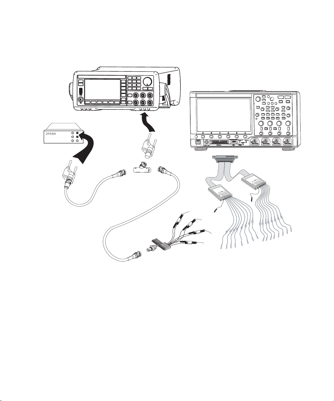
Page 21

Testing Performance 2
To construct the test connector (for use with MSO models only)
Keysight 2000/3000 X-Series oscilloscopes that have digital channels enabled
require the test connector described below. Follow the steps to build the test
connector.
Table 3 Materials required to construct the test connectors
Description Recommended Part Qty
BNC (f) Connector Keysight 1250-1032 or
Pomona 4578
Berg Strip, 8-by-2 3M .100” x .100” Pin Strip
Header or similar
Jumper wire
1 Obtain a BNC connector and an 8-by-2 section of Berg strip. A longer strip can
be cut to length using wire cutters.
2 On one side of the Berg strip, solder a jumper wire to all of the pins (shown in
Figure 1 on page 22).
3 On the other side of the Berg strip, solder another jumper wire to all of the pins.
4 Solder the center of the BNC connector to a center pin on one of the rows on
the Berg strip.
5 Solder the ground tab of the BNC connector to a center pin on the other row on
the Berg strip.
1
1 strip, cut to length (8x2)
2000/3000 X-Series Oscilloscopes Service Guide 21
Page 22

2 Testing Performance
Jumper (2)
Signal Lead
(from scope’s MSO cable)
8 x 2 Berg Strip
BNC Panel Mount Connector
Ground Lead
(from scope’s MSO cable)
Figure 1 Constructing the 8-by-2 Connector
22 2000/3000 X-Series Oscilloscopes Service Guide
Page 23

To test digital channels (MSO models only)
The acquisition system testing provides confidence that the acquisition system is
functioning correctly. It does not, however, check a particular specification.
1 Disconnect all probes from the circuit under test and from any other input
source.
2 Using probe leads and grabbers, connect digital channels D0, D1, D2, and D3
to the Probe Comp signal on the center of the front panel.
3 Press the [AutoScale] key.
If four square waves appear, the acquisition system is functioning correctly.
If the square waves do not appear, go to the “Troubleshooting” chapter. Then
return here to finish testing the digital channels.
4 Disconnect the digital channels from the calibration point.
5 Use steps 2 and 3 to test the following sets of digital channels. After you test
one set of digital channels, remove them before connecting the next set.
• D4, D5, D6, D7
• D8, D9, D10, D11 (on 3000 X-Series models)
• D12, D13, D14, D15 (on 3000 X-Series models)
Testing Performance 2
2000/3000 X-Series Oscilloscopes Service Guide 23
Page 24

2 Testing Performance
To verify digital channel threshold accuracy (MSO models only)
This test verifies the digital channel threshold accuracy specification of the
Keysight 2000/3000 X-Series oscilloscopes.
Threshold accuracy test limits: ±(100 mV + 3% of threshold setting)
When to Test
You should perform this test every 12 months or after 2000 hours of operation,
whichever comes first.
What to Test
Use these instructions to test the threshold settings of digital channels D7-D0.
Then, use the same instructions to test digital channels D15-D8 (on
3000 X-Series).
Verifying Test Results
After each threshold test, record the voltage reading in the Performance Test
Record on page 53. To verify whether a test passes, verify that the voltage reading
is within the limits in the Performance Test Record.
24 2000/3000 X-Series Oscilloscopes Service Guide
Page 25

Testing Performance 2
Table 4 Equipment Required to Test Digital Channel Threshold Accuracy
Equipment Critical Specifications Recommended Model/Part
Digital Multimeter 0.1 mV resolution, 0.005% accuracy Keysight 34401A/34461A
Precision Source DC voltage of -5.5 V to 5.5 V, 10 mV resolution Keysight B2912A/B2962A
Adapter (qty 2) BNC(f) to banana (m) Keysight 1251-2277
BNC Tee BNC Tee (m) (f) (f) Keysight 1250-0781 or Pomona 3285
50 Ω BNC Cable BNC - BNC, 48” length Keysight 8120-1840
BNC Test Connector,
8-by-2
Probe Cable No substitute 16-chanel: Keysight N6450-60001 or
User-built (See page 21)
N2756-60001
8-channel: Keysight N6459-60001 or
N2755-60001
1 Turn on the test equipment and the oscilloscope. Let them warm up for 30
minutes before starting the test.
2 Set up the precision source.
a Set the precision source to provide a DC offset voltage at the Channel 1
output.
Note: Set the Low Force terminal of the Precision Source to its "Floating"
state to prevent offset error caused by ground loop current from the
Precision Source ground to the DUT ground.
b Use the multimeter to monitor the precision source DC output voltage.
3 Use the 8-by-2 test connector and the BNC cable assembly to connect digital
channels D0-D7 to one side of the BNC Tee. Then connect the D0-D7 ground
lead to the ground side of the 8-by-2 connector. See Figure 2.
2000/3000 X-Series Oscilloscopes Service Guide 25
Page 26
2 Testing Performance
Precision Source
Probe
Cables
Channels
8 - 15
Channels
0 - 7
Test
Connector
2000/3000 X-Series Oscilloscope
Digital
Multimeter
BNC Tee
BNC-Bananna
Cable
Figure 2 Setting Up Equipment for Digital Channel Threshold Accuracy Test
4 Use a BNC-banana cable to connect the multimeter to the other side of the
BNC Tee.
5 Connect the BNC Tee to the Channel 1 output of the precision source as shown
in Figure 2.
6 On the oscilloscope, press the [Digital] key, then press the Thresholds softkey,
then press the D7 - D0 softkey repeatedly until the check mark is next to User.
26 2000/3000 X-Series Oscilloscopes Service Guide
Page 27

Testing Performance 2
7 Press the User softkey to the right of the D7 - D0 softkey, then turn the Entry
knob ( ) on the front panel of the oscilloscope to set the threshold test
settings as shown in Table 5.
Table 5 Threshold Accuracy Voltage Test Settings
Threshold voltage setting (in
oscilloscope User softkey)
+5.00 V +5.250 V ±1 mV dc Lower limit = +4.750 V
–5.00 V –4.750 V ±1 mV dc Lower limit = –5.250 V
0.00 V +100m V ±1 mV dc Upper limit = +100 mV
DC offset voltage setting (on
precision source)
Limits
Upper limit = +5.250 V
Upper limit = –4.750 V
Lower limit = –100 mV
8 Do the following steps for each of the threshold voltage levels shown in Tab le 5.
a Set the threshold voltage shown in the User softkey using the Entry knob on
the oscilloscope.
b Enter the corresponding DC offset voltage on the precision source front
panel. Then use the multimeter to verify the voltage.
Digital channel activity indicators are displayed on the status line at the top
of the oscilloscope display. The activity indicators for D7-D0 should show all
of the channels at digital high levels.
c Use the knob on the precision source to decrease the offset voltage, in
increments of 10 mV, until the activity indicators for digital channels D7-D0
are all at digital low levels. Record the precision source voltage in the
Performance Test Record (see page 53).
d Use the knob on the precision source to increase the offset voltage, in
increments of 10 mV, until the activity indicators for digital channels D7-D0
are all at digital high levels. Record the precision source voltage in the
Performance Test Record (see page 53).
Before proceeding to the next step, make sure that you have recorded the
precision source voltage levels for each of the threshold settings shown in
Tabl e 5.
2000/3000 X-Series Oscilloscopes Service Guide 27
Page 28

2 Testing Performance
9 When testing 3000 X-Series MSOs, use the 8-by-2 test connector to connect
digital channels D15-D8 to the output of the precision source. Then connect
the D15-D8 ground lead to the ground side of the 8-by-2 connector.
10 Repeat this procedure (steps 6 through 8) for digital channels D15-D8 to verify
threshold accuracy and record the threshold levels in the Performance Test
Record (see page 53). Be sure to set the thresholds with the User softkey for the
appropriate set of channels.
To verify DC vertical gain accuracy
This test verifies the accuracy of the analog channel DC vertical gain for each
channel.
In this test, you will measure the dc voltage output of a precision source using the
oscilloscope’s Average - Full Screen voltage measurement and compare the results
with the multimeter reading.
Table 6 DC Vertical Gain Accuracy Test Limits
Models Test Limits Notes
2000 X-Series ±3% of full scale (>= 10 mV/div);
±4% of full scale (< 10 mV/div)
3000 X-Series ±2.0% of full scale
28 2000/3000 X-Series Oscilloscopes Service Guide
• Full scale is defined as 32 mV on the 2 mV/div range
and the 1 mV/div range.
• Full scale on all other ranges is defined as 8 d ivisions
times the V/div setting.
Page 29

Testing Performance 2
Table 7 Equipment Required to Verify DC Vertical Gain Accuracy
Equipment Critical Specifications Recommended Model/Part
Precision Source DC voltage of 7 mV to 35 V, 0.1 mV resolution Keysight B2912A/B2962A
Digital multimeter Better than 0.01% accuracy Keysight 34401A/34461A
50 Ω BNC Cable (qty 2) BNC - BNC, 48” length Keysight 8120-1840
Adapter (qty 2) BNC (f) to banana (m) Keysight 1251-2277
BNC Tee BNC tee (m) (f) (f) Keysight 1250-0781 or Pomona 3285
Shorting cap BNC Keysight 1250-0774
Blocking capacitor Note: if a BNC blocking capacitor is not available use
an SMA blocking capacitor.
1 Press [Save/Recall] > Default/Erase > Factory Default to recall the factory default
setup.
2 If you are testing a 2000 X-Series oscilloscope, set the probe attenuation to 1:1
on the analog channel you are testing (for example, [1] > Probe > Probe; then,
turn the Entry knob to select 1.00 : 1).
3 Set up the oscilloscope.
a Adjust the horizontal scale to 200.0 us/div.
b Set the Volts/Div setting to the value in the first line in Table 8 or Tab le 9
(depending on the oscilloscope model).
c Adjust the channel’s vertical position knob to place the baseline (reference
level) at 0.5 major division from the bottom of the display.
Keysight 11742A +
Pomona 4289 +
Pomona 5088
2000/3000 X-Series Oscilloscopes Service Guide 29
Page 30

2 Testing Performance
Table 8 Settings Used to Verify DC Vertical Gain Accuracy, 2000 X-Series Models
Volts/Div Setting Precision Source Setting Test Limits
5 V/Div 35 V 33.8 V to 36.2 V
2 V/Div 14 V 13.52 V to 14.48 V
1V/Div 7V 6.76V to 7.24V
500 mV/Div 3.5 V 3.38 V to 3.62 V
200 mV/Div 1.4 V 1.352 V to 1.448 V
100 mV/Div 700 mV 676 mV to 724 mV
50 mV/Div 350 mV 338 mV to 362 mV
20 mV/Div 140 mV 135.2 mV to 144.8 mV
10 mV/Div 70 mV 67.6 mV to 72.4 mV
5mV/Div
2mV/Div
1mV/Div
1
Reduce Noise" on page 34.
1
1, 2
1, 2
A blocking capacitor is required at this range to reduce noise. See “Use a Blocking Capacitor to
35 mV 33.4 mV to 36.6 mV
14 mV 12.72 mV to 15.28 mV
7 mV 5.72 mV to 8.28 mV
2
Full scale is defined as 32 mV on the 2 mV/div and the 1 mV/div range. Full scale on all other ranges
is defined as 8 divisions times the V/div setting.
30 2000/3000 X-Series Oscilloscopes Service Guide
Page 31

Testing Performance 2
Table 9 Settings Used to Verify DC Vertical Gain Accuracy, 3000 X-Series Models
Volts/Div Setting Precision Source Setting Test Limits
5 V/Div 35 V 34.2 V to 35.8 V
2 V/Div 14 V 13.68 V to 14.32 V
1V/Div 7V 6.84V to 7.16V
500 mV/Div 3.5 V 3.42 V to 3.58 V
200 mV/Div 1.4 V 1.368 V to 1.432 V
100 mV/Div 700 mV 684 mV to 716 mV
50 mV/Div 350 mV 342 mV to 358 mV
20 mV/Div 140 mV 136.8 mV to 143.2 mV
10 mV/Div 70 mV 68.4 mV to 71.6 mV
5mV/Div
2mV/Div
1mV/Div
1
Reduce Noise" on page 34.
1
1, 2
1, 2
A blocking capacitor is required at this range to reduce noise. See “Use a Blocking Capacitor to
35 mV 34.2 mV to 35.8 mV
14 mV 13.36 mV to 14.64 mV
7 mV 6.36 mV to 7.64 mV
2
Full scale is defined as 32 mV on the 2 mV/div range and the 1 mV/div range. Full scale on all other
ranges is defined as 8 divisions times the V/d iv setting.
d Press the [Acquire] key.
e Then press the Acq Mode softkey and select Averaging.
f Then press the #Avgs softkey and set it to 64.
Wait a few seconds for the measurement to settle.
4 Add a measurement for the average voltage:
a Press the [Meas] key.
b Press Source; then, turn the Entry knob (labeled on the front panel) to
select the channel you are testing.
c Press Type:; then, turn the Entry knob to select Average - Full Screen, and press
Add Measurement.
2000/3000 X-Series Oscilloscopes Service Guide 31
Page 32

2 Testing Performance
Precision Source
Oscilloscope
Digital
Multimeter
BNC Tee
BNC (f) to dual
bananna adapter
5 Read the “current” average voltage value as V1.
6 Use the BNC tee and cables to connect the precision source /power supply to
both the oscilloscope and the multimeter (see Figure 3).
Note: Set the Low Force terminal of the Precision Source to its "Floating" state
to prevent offset error caused by ground loop current from the Precision Source
ground to the DUT ground.
Figure 3 Setting up Equipment for DC Vertical Gain Accuracy Test
32 2000/3000 X-Series Oscilloscopes Service Guide
Page 33

Testing Performance 2
7 Adjust the output so that the multimeter reading displays the first Volts/div
precision source setting value in Table 8 or Tabl e 9 (depending on the
oscilloscope model).
8 Disconnect the multimeter.
9 Wait until the measurement settles.
10 Read the “current” average voltage value again as V2.
11 Calculate the difference V2 - V1.
The difference in average voltage readings should be within the test limits of
Tabl e 8 or Table 9 (depending on the oscilloscope model).
If a result is not within the test limits, go to the “Troubleshooting” chapter. Then
return here.
12 Disconnect the precision source from the oscilloscope.
13 Repeat this procedure to check the DC vertical gain accuracy with the
remaining Volts/div setting values in Table 8 or Table 9 (depending on the
oscilloscope model).
14 Finally, repeat this procedure for the remaining channels to be tested.
2000/3000 X-Series Oscilloscopes Service Guide 33
Page 34

2 Testing Performance
To oscilloscope input
BNC shorting
cap
Blocking
Capacitor
Use a Blocking Capacitor to Reduce Noise
On the more sensitive ranges, such as 1mV/div, 2mV/div, and 5mV/div, noise
may be a factor. To eliminate the noise, add a BNC Tee, blocking capacitor, and
shorting cap at the oscilloscope channel input to shunt the noise to ground. See
Figure 4. If a BNC capacitor is not available, use an SMA blocking capacitor,
adapter, and cap. See “Blocking capacitor in the equipment list on page 20 for
details.
Figure 4 Using a Blocking Capacitor to Reduce Noise
34 2000/3000 X-Series Oscilloscopes Service Guide
Page 35

Testing Performance 2
To verify dual cursor accuracy
This test verifies the dual cursor accuracy for each analog channel.
This test is similar to the test for verifying the DC vertical gain, except you will
measure the dc voltage output of a precision source using dual cursors on the
oscilloscope and compare the results with the multimeter reading.
Dual cursor accuracy test limits: ±[DC vertical gain accuracy + 0.5% full scale]
For the DC vertical gain accuracy test limits, see Table 6 on page 28.
Table 10 Equipment Required to Verify Dual Cursor Accuracy
Equipment Critical Specifications Recommended Model/Part
Precision Source DC voltage of 7 mV to 35 V, 0.1 mV resolution Keysight B2912A/B2962A
Digital multimeter Better than 0.01% accuracy Keysight 34401A/34461A
50 Ω BNC Cable (qty 2) BNC - BNC, 48” length Keysight 8120-1840
Adapter (qty 2) BNC (f) to banana (m) Keysight 1251-2277
BNC Tee BNC tee (m) (f) (f) Keysight 1250-0781 or Pomona 3285
Shorting cap BNC Keysight 1250-0774
Blocking capacitor Note: if a BNC blocking capacitor is not available use
an SMA blocking capacitor.
1 Press [Save/Recall] > Default/Erase > Factory Default to recall the factory default
setup.
2 If you are testing a 2000 X-Series oscilloscope, set the probe attenuation to 1:1
on the analog channel you are testing (for example, [1] > Probe > Probe; then,
turn the Entry knob to select 1.00 : 1).
3 Set up the oscilloscope.
a Set the Volts/Div setting to the value in the first line in Table 1 1 or Table 12
(depending on the oscilloscope model).
b Adjust the channel 1 position knob to place the baseline at 0.5 major division
from the bottom of the display.
2000/3000 X-Series Oscilloscopes Service Guide 35
Keysight 11742A +
Pomona 4289 +
Pomona 5088
Page 36

2 Testing Performance
Table 11 Settings Used to Verify Dual Cursor Accuracy, 2000 X-Series Models
Volts/Div Setting Precision Source Setting Test Limits
5 V/Div 35 V 33.6 V to 36.4 V
2 V/Div 14 V 13.44 V to 14.56 V
1V/Div 7V 6.72V to 7.28V
500 mV/Div 3.5 V 3.36 V to 3.64 V
200 mV/Div 1.4 V 1.344 V to 1.456 V
100 mV/Div 700 mV 672 mV to 728 mV
50 mV/Div 350 mV 336 mV to 364 mV
20 mV/Div 140 mV 134.4 mV to 145.6 mV
10 mV/Div 70 mV 67.2 mV to 72.8 mV
5mV/Div
2mV/Div
1mV/Div
1
Reduce Noise" on page 39.
1
1, 2
1, 2
A blocking capacitor is required at this range to reduce noise. See “Use a Blocking Capacitor to
35 mV 33.2 mV to 36.8 mV
14 mV 12.56 mV to 15.44 mV
7 mV 5.56 mV to 8.44 mV
2
Full scale is defined as 32 mV on the 2 mV/div range and the 1 mV/div range. Full scale on all other
ranges is defined as 8 divisions times the V/d iv setting.
36 2000/3000 X-Series Oscilloscopes Service Guide
Page 37

Testing Performance 2
Table 12 Settings Used to Verify Dual Cursor Accuracy, 3000 X-Series Models
Volts/Div Setting Precision Source Setting Test Limits
5 V/Div 35 V 34.0 V to 36.0 V
2 V/Div 14 V 13.6 V to 14.4 V
1V/Div 7V 6.8V to 7.2V
500 mV/Div 3.5 V 3.4 V to 3.6 V
200 mV/Div 1.4 V 1.36 V to 1.44 V
100 mV/Div 700 mV 680 mV to 720 mV
50 mV/Div 350 mV 340 mV to 360 mV
20 mV/Div 140 mV 136 mV to 144 mV
10 mV/Div 70 mV 68 mV to 72 mV
5mV/Div
2mV/Div
1mV/Div
1
Reduce Noise" on page 39.
1
1, 2
1, 2
A blocking capacitor is required at this range to reduce noise. See “Use a Blocking Capacitor to
35 mV 34 mV to 36 mV
14 mV 13.2 mV to 14.8 mV
7mV 6.2mV to 7.8mV
2
Full scale is defined as 32 mV on the 2 mV/div range and the 1 mV/div range. Full scale on all other
ranges is defined as 8 divisions times the V/d iv setting.
c Press the [Acquire] key.
d Then press the Acq Mode softkey and select Averaging.
e Then press the #Avgs softkey and set it to 64.
Wait a few seconds for the measurement to settle.
4 Press the [Cursors] key, set the Mode softkey to Normal, then press the XY softkey
and select Y. Press the Y1 softkey, then use the Entry knob (labeled on the
front panel) to set the Y1 cursor on the baseline of the signal.
5 Use the BNC tee and cables to connect the precision source /power supply to
both the oscilloscope and the multimeter (see Figure 5).
2000/3000 X-Series Oscilloscopes Service Guide 37
Page 38

2 Testing Performance
Precision Source
Oscilloscope
Digital
Multimeter
BNC Tee
BNC (f) to dual
bananna adapter
Note: Set the Low Force terminal of the Precision Source to its "Floating" state
to prevent offset error caused by ground loop current from the Precision Source
ground to the DUT ground.
Figure 5 Setting up Equipment for Dual Cursor Accuracy Test
6 Adjust the output so that the multimeter reading displays the first Volts/div
precision source setting value in Table 11 or Ta ble 12 (depending on the
oscilloscope model).
7 Disconnect the multimeter.
38 2000/3000 X-Series Oscilloscopes Service Guide
Page 39

Testing Performance 2
To oscilloscope input
BNC shorting
cap
Blocking
Capacitor
8 Wait until the measurement settles.
9 Press the Y2 softkey, then position the Y2 cursor to the center of the voltage
trace using the Entry knob.
The ΔY value on the lower line of the display should be within the test limits of
Tabl e 11 or Table 12 (depending on the oscilloscope model).
If a result is not within the test limits, go to the “Troubleshooting” chapter. Then
return here.
10 Disconnect the precision source from the oscilloscope.
11 Repeat this procedure to check the dual cursor accuracy with the remaining
Volts/div setting values in Tab le 11 or Table 12 (depending on the oscilloscope
model).
12 Finally, repeat this procedure for the remaining channels to be tested.
Use a Blocking Capacitor to Reduce Noise
On the more sensitive ranges, such as 1mV/div, 2mV/div, and 5mV/div, noise
may be a factor. To eliminate the noise, add a BNC Tee, blocking capacitor, and
shorting cap at the oscilloscope channel input to shunt the noise to ground. See
Figure 6. If a BNC capacitor is not available, use an SMA blocking capacitor,
adapter, and cap. See “Blocking capacitor in the equipment list on page 20 for
details.
Figure 6 Using a Blocking Capacitor to Reduce Noise
2000/3000 X-Series Oscilloscopes Service Guide 39
Page 40

2 Testing Performance
To verify bandwidth (-3 dB)
This test checks the bandwidth (-3 dB) of the oscilloscope. In this test you will use
a signal generator and a power meter.
Table 13 Bandwidth (-3 dB) Test Limits
Models Test Limits
1 GHz Models All channels (-3 dB), dc to 1 GHz
500 MHz Models All channels (-3 dB), dc to 500 MHz
350 MHz Models All channels (-3 dB), dc to 350 MHz
200 MHz Models All channels (-3 dB), dc to 200 MHz
100 MHz Models All channels (-3 dB), dc to 100 MHz
70 MHz Models All channels (-3 dB), dc to 70 MHz
Table 14 Equipment Required to Verify Bandwidth (-3 dB)
Equipment Critical Specifications Recommended Model/Part
Signal Generator 100 kHz - 1 GHz at 200 mVrms Keysight N5171B
Power Meter 1 MHz - 1 GHz ±3% accuracy Keysight N1914A
Power Sensor 1 MHz - 1 GHz ±3% accuracy Keysight E9304A or N8482A
Power Splitter outputs differ by < 0.15 dB Keysight 11667A
Cable Type N (m) 24 inch Keysight 11500B
Adapter Type N (m) to BNC (m) Keysight 1250-0082 or
Pomona 3288 with Pomona 3533
50 Ohm Feedthrough
Termination
Ω BNC (f) to BNC (m), when testing 2000 X-Series
50
oscilloscopes
Keysight 0960-0301
40 2000/3000 X-Series Oscilloscopes Service Guide
Page 41

Testing Performance 2
1 Connect the equipment (see Figure 7).
a Use the N cable to connect the signal generator to the input of the power
splitter input.
b Connect the power sensor to one output of the power splitter.
c Use an N-to-BNC adapter to connect the other splitter output to the
channel 1 input.
Oscilloscope
Signal
Generator
N to BNC Adapter
Power Splitter
Power Sensor
N Cable
Power
Meter
Figure 7 Setting Up Equipment for Bandwid th (-3 dB) Verification Test
2000/3000 X-Series Oscilloscopes Service Guide 41
Page 42

2 Testing Performance
Vin
1MHz
Pmeas
1MHz
50Ω×=
2 Set up the power meter.
Set the power meter to display measurements in units of watts.
3 Set up the oscilloscope.
a Press the [Default Setup] key.
b Set channel 1 Coupling to DC.
c With 2000 X-Series oscilloscopes, connect a 50 ohm feedthrough
termination.
With 3000 X-Series oscilloscopes, set channel 1 Imped to 50 Ohm.
d Set the time base to 500 ns/div.
e Set the Volts/Div for channel 1 to 200 mV/div.
f Press the [Acquire] key, then press the Averaging softkey.
g Turn the Entry knob to set # Avgs to 8 averages.
4 Set the signal generator for 1 MHz and six divisions of amplitude.
The signal on the oscilloscope screen should be about five cycles at six
divisions amplitude.
5 Set up the Amplitude measurement
a Press the [Meas] key.
b Press the Clear Meas softkey and then the Clear All softkey.
c Press the Type: softkey and use the Entry knob to select AC RMS - Full Screen
(Std Deviation) within the select menu.
d Press the Add Measurement softkey.
6 Note the oscilloscope AC RMS - FS(1) reading at the bottom of the screen.
(This is the RMS value with any dc offset removed.)
7 Note the oscilloscope Std Dev(1) reading at the bottom of the screen. (This will
be used in later calculations.)
8 Set the power meter Cal Factor % to the 1 MHz value on the calibration chart
on the power sensor.
9 Note the reading on the power meter and covert to Vrms using the expression:
For example, if the power meter reading is 892 uW, then Vin
1/2
50Ω)
42 2000/3000 X-Series Oscilloscopes Service Guide
= 211.2 mV
rms
.
= (892*10-6 *
1MHz
Page 43

Testing Performance 2
Vin
maxfreq
Pmeas
maxfreq
50Ω×=
respons e(dB) = 20 log
10
MHz 1 MHz 1
freqmax freqmax
Vin / Vout
Vin / Vout
10 Change the signal generator output frequency according to the maximum
frequency for the oscilloscope using the following:
• 1GHz Models: 1GHz
• 500 MHz Models: 500 MHz
• 350 MHz Models: 350 MHz
• 200 MHz Models: 200 MHz
• 100 MHz Models: 100 MHz
• 70 MHz Models: 70 MHz
11 Referencing the frequency from step 9, set the power meter Cal Factor % to the
frequency value on the calibration chart on the power sensor.
12 Set the oscilloscope sweep speed according to the following:
• 1 GHz Models: 500 ps/div
• 500 MHz Models: 1 ns/div
• 350 MHz Models: 2 ns/div
• 200 MHz Models: 2 ns/div
• 100 MHz Models: 5 ns/div
• 70 MHz Models: 5 ns/div
13 Note the oscilloscope Std Dev(1) reading at the bottom of the screen.
14 Note the reading on the power meter and covert to Vrms using the expression:
Example If:
2000/3000 X-Series Oscilloscopes Service Guide 43
15 Calculate the response using the expression:
Pmeas
Std Dev(n)
Pmeas
Std Dev(n)
1_MHz
1MHz
max_freq
max freq
= 892 uW
= 210.4 mV
= 687 uW
= 161.6 mV
Page 44

2 Testing Performance
response(dB) = 20 log
10
mV 185.3 / mV 161.6
= -1.16 dB
Then after converting the values from the power meter to Vrms:
mV211.2mV/ 210.4
16 The result from step 14 should be between +3.0 dB and -3.0 dB. Record the
result in the Performance Test Record (see page 53).
17 Move the power splitter from the channel 1 to the channel 2 input.
18 Turn off the current channel and turn on the next channel using the channel
keys.
19 Repeat steps 3 through 17 for the remaining channels, setting the parameters
of the channel being tested where appropriate.
44 2000/3000 X-Series Oscilloscopes Service Guide
Page 45

Testing Performance 2
To verify time base accuracy
This test verifies the accuracy of the time base. In this test you will measure the
absolute error of the time base oscillator and compare the results to the
specification.
Table 15 Equipment Required to Verify Time Base Accuracy
Equipment Critical Specifications Recommended Model/Part
Signal Generator 100 kHz - 1 GHz, 0.01 Hz frequency resolution,
jitter: < 2ps
50 Ω BNC Cable BNC - BNC, 48” length Keysight 8120-1840
50 Ohm Feedthrough
Termination
50Ω BNC (f) to BNC (m), when testing 2000 X-Series
oscilloscopes
1 Set up the signal generator.
a Set the output to 10 MHz, approximately 1 V
2 Connect the output of the signal generator to oscilloscope channel 1 using the
BNC cable. When testing 2000 X-Series oscilloscopes, also connect a 50 ohm
feedthrough termination between the channel 1 input and the BNC cable.
3 Set up the oscilloscope:
a Press [AutoScale].
b Set the oscilloscope Channel 1 vertical sensitivity to 200 mv/div.
c Set the oscilloscope horizontal sweep speed control to 5 ns/div.
d Adjust the intensity to get a sharp, clear trace.
e Adjust the oscilloscope’s trigger level so that the rising edge of the
waveform at the center of the screen is located where the center horizontal
and vertical grid lines cross (center screen).
f Ensure the horizontal position control is set to 0.0 seconds.
Keysight N5171B
Keysight 0960-0301
sine wave.
pp
2000/3000 X-Series Oscilloscopes Service Guide 45
Page 46
2 Testing Performance
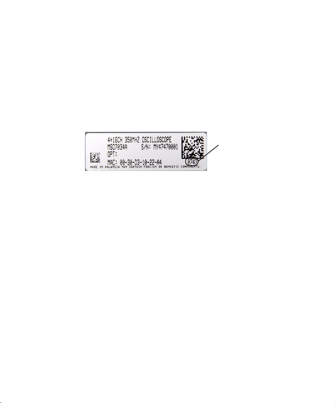
Date Code:
0747
07 = Year
47 = Week
4 Make the measurement.
a Set oscilloscope horizontal sweep speed control to 1 ms/div.
b Set horizontal position control to +1 ms (rotate control CCW).
c Set the oscilloscope horizontal sweep speed control to 5 ns/div.
d Record the number of nanoseconds from where the rising edge crosses the
center horizontal grid line to the center vertical grid line. The number of
nanoseconds is equivalent to the time base error in ppm.
e Use the date code on the oscilloscope’s serial tag to calculate the number of
years since manufacture. Include any fractional portion of a year.
f Use the following formula to calculate the test limits.
Time base accuracy limit: ±25 ppm ±5 ppm per year (aging)
g Record the result and compare it to the limits in the Performance Test
Record (see page 53).
46 2000/3000 X-Series Oscilloscopes Service Guide
Page 47

To verify trigger sensitivity
This test verifies the trigger sensitivity. In this test, you will apply a sine wave to
the oscilloscope at the upper bandwidth limit. You will then decrease the
amplitude of the signal to the specified levels, and check to see if the oscilloscope
is still triggered.
Test limits for:
• Internal trigger sensitivity on all models:
• < 10 mV/div: greater of 1 div or 5 mV
• >= 10 mV/div: 0.6 div
• External trigger sensitivity on all models:
• DC to 100 MHz: < 200 mV
• 100 MHz - 200 MHz: < 350 mV
Table 16 Equipment Required to Verify Trigger Sensitivity
Testing Performance 2
pp
pp
pp
Equipment Critical Specifications Recommended Model/Part
Signal Generator 25 MHz, 100 MHz, 350 MHz, 500 MHz, and 1 GHz sine
waves
Power splitter Outputs differ < 0.15 dB Keysight 11667A
Power Meter Keysight N1914A
Power Sensor Keysight E9304A or N8482A
Cable Type N (m) 24 inch Keysight 11500B
Adapter Type N (m) to BNC (m) Keysight 1250-0082 or
50 Ohm Feedthrough
Termination
Ω BNC (f) to BNC (m) Keysight 0960-0301
50
Keysight N5171B
Pomona 3288 with Pomona 3533
2000/3000 X-Series Oscilloscopes Service Guide 47
Page 48

2 Testing Performance
Test Internal Trigger Sensitivity (all models)
1 On the oscilloscope, press the [Default Setup] key.
2 Press the [Mode/Coupling] key; then, press the Mode softkey to select Normal.
3 Connect the equipment (see Figure 8).
a Connect the signal generator output to the oscilloscope channel 1 input.
Oscilloscope
Signal
Generator
N to BNC Adapter
N Cable
Figure 8 Setting Up Equipment for Internal Trigger Sensitivity Test
b With 2000 X-Series oscilloscopes, connect a 50 ohm feedthrough
termination between the channel 1 input and the BNC cable.
With 3000 X-Series oscilloscopes, set channel 1 Imped to 50 Ohm.
4 To verify the trigger sensitivity at the oscilloscope’s maximum bandwidth, set
the output frequency of the signal generator to the maximum bandwidth of the
oscilloscope:
• 1GHz models: 1GHz.
• 500 MHz models: 500 MHz.
• 350 MHz models: 350 MHz.
48 2000/3000 X-Series Oscilloscopes Service Guide
Page 49

Testing Performance 2
• 200 MHz models: 200 MHz.
• 100 MHz models: 100 MHz.
• 70 MHz models: 70 MHz.
5 Perform these steps to test at the 5 mV/div setting:
a Set the signal generator amplitude to about 10 mV
b Press the [AutoScale] key.
c Set the time base to 10 ns/div.
d Set channel 1 to 5 mV/div.
e Decrease the amplitude from the signal generator until 1 vertical division of
the signal (about 5 mV
The trigger is stable when the displayed waveform is stable. If the trigger is
not stable, try adjusting the trigger level. If adjusting the trigger level makes
the trigger stable, the test still passes. If adjusting the trigger does not help,
see the “Troubleshooting” chapter. Then return here.
f Record the result as Pass or Fail in the Performance Test Record (see
page 53).
g Repeat this step for the remaining oscilloscope channels.
6 Perform these steps to test at the 10 mV/div setting:
a Set the signal generator amplitude to about 20 mV
b Press the [AutoScale] key.
c Set the time base to 10 ns/div.
d Set channel 1 to 10 mV/div.
e Decrease the amplitude from the signal generator until 0.6 vertical divisions
of the signal (about 6 mV
The trigger is stable when the displayed waveform is stable. If the trigger is
not stable, try adjusting the trigger level. If adjusting the trigger level makes
the trigger stable, the test still passes. If adjusting the trigger does not help,
see the “Troubleshooting” chapter. Then return here.
f Record the result as Pass or Fail in the Performance Test Record (see
page 53).
g Repeat this step for the remaining oscilloscope channels.
) is displayed.
pp
) is displayed.
pp
pp
pp
.
.
2000/3000 X-Series Oscilloscopes Service Guide 49
Page 50

2 Testing Performance
Test External Trigger Sensitivity
This test applies to all models.
Verify the external trigger sensitivity at these settings:
• 100 MHz, 200 mV
• 200 MHz, 350 mV
1 Connect the equipment (see Figure 9).
a Use the N cable to connect the signal generator to the power splitter input.
b Connect one output of the power splitter to the Aux Trig input through a 50Ω
feedthrough termination.
c Connect the power sensor to the other output of the power splitter.
pp
pp
50 2000/3000 X-Series Oscilloscopes Service Guide
Page 51

Oscilloscope
50 Ohm Feedthrough
N to BNC Adapter
Testing Performance 2
Signal
Generator
Power Splitter
Power Sensor
Power
Meter
Figure 9 Setting Up Equipment for 4-Channel External Trigger Sensitivity Test
2000/3000 X-Series Oscilloscopes Service Guide 51
N Cable
Page 52

2 Testing Performance
2 Set up the oscilloscope.
3 Change the signal generator output frequency to 100 MHz or 200 MHz.
4 Set the power meter Cal Factor % to the appropriate value (100 MHz or
5 Adjust the signal generator output for reading on the power meter of:
a Press the [Default Setup] key.
b Press the [Mode/Coupling] key; then, press the Mode softkey to select Normal.
200 MHz) on the calibration chart on the power sensor. If necessary, do a linear
interpolation if a 100 MHz or 200 MHz factor is not included in the power
meter’s calibration chart.
Signal Generator
Frequency
100 MHz 200 mV
200 MHz 350 mVpp= 123.74 mV rms, Power = Vin2/50Ω =
6 Press the [Trigger] key, then press the Source softkey to set the trigger source to
Calculation Power Meter
Reading
= 70.71 mV rms, Power = Vin2/50Ω =
pp
70.71 mV2/50Ω
123.74 mV2/50Ω
100 μW
306 μW
External.
7 Check for stable triggering and adjust the trigger level if necessary. Triggering
is indicated by the Trig’d indicator at the top of the display. When it is flashing,
the oscilloscope is not triggered. When it is not flashing, the oscilloscope is
triggered.
8 Record the results as Pass or Fail in the Performance Test Record (see
page 53).
If the test fails, see the “Troubleshooting” chapter. Then return here.
52 2000/3000 X-Series Oscilloscopes Service Guide
Page 53

Testing Performance 2
Keysight 2000 X-Series Oscilloscopes Performance Test Record
Serial No. ______________________________________ Test by _____________________________
Test Interval ____________________________________ Work Order No. ______________________
Recommended Next Testing ________________________ Temperature ____________
Threshold Specification Limits Ch D7-D0
Accuracy Test 5 V - 250 mV 4.750 V ________
(100 mV + 3% of
threshold setting)
DC Vertical Gain Accuracy
Range Power Supply Setting Test Limits Channel 1 Channel 2 Channel 3* Channel 4*
5 V/Div 35 V 33.8 V to 36.2 V ________ ________ ________ ________
2 V/Div 14 V 13.52 V to 14.48 V ________ ________ ________ ________
1 V/Div 7 V 6.76 V to 7.24 V ________ ________ ________ ________
500 mV/Div 3.5 V 3.38 V to 3.62 V ________ ________ ________ ________
200 mV/Div 1.4 V 1.352 V to 1.448 V ________ ________ ________ ________
100 mV/Div 700 mV 676 mV to 724 mV ________ ________ ________ ________
50 mV/Div 350 mV 338 mV to 362 mV ________ ________ ________ ________
20 mV/Div 140 mV 135.2 mV to 144.8 mV ________ ________ ________ ________
10 mV/Div 70 mV 67.6 mV to 72.4 mV ________ ________ ________ ________
5 mV/Div 35 mV 33.4 mV to 36.6 mV ________ ________ ________ ________
2 mV/Div 14 mV 12.72 mV to 15.28 mV ________ ________ ________ ________
1 mV/Div 7 mV 5.72 mV to 8.28 mV ________ ________ ________ ________
5 V + 250 mV 5.250 V ________
-5 V - 250 mV -5.250 V ________
-5 V + 250 mV -4.750 V ________
0 V - 100 mV -100 mV ________
0 V + 100 mV 100 mV ________
Continued on next page.
2000/3000 X-Series Oscilloscopes Service Guide 53
Page 54

2 Testing Performance
Dual Cursor Accuracy
Range Power Supply Setting Test Limits Channel 1 Channel 2 Channel 3* Channel 4*
5 V/Div 35 V 33.6 V to 36.4 V ________ ________ ________ ________
2 V/Div 14 V 13.44 V to 14.56 V ________ ________ ________ ________
1 V/Div 7 V 6.72 V to 7.28 V ________ ________ ________ ________
500 mV/Div 3.5 V 3.36 V to 3.64 V ________ ________ ________ ________
200 mV/Div 1.4 V 1.344 V to 1.456 V ________ ________ ________ ________
100 mV/Div 700 mV 672 mV to 728 mV ________ ________ ________ ________
50 mV/Div 350 mV 336 mV to 364 mV ________ ________ ________ ________
20 mV/Div 140 mV 134.4 mV to 145.6 mV ________ ________ ________ ________
10 mV/Div 70 mV 67.2 mV to 72.8 mV ________ ________ ________ ________
5 mV/Div 35 mV 33.2 mV to 36.8 mV ________ ________ ________ ________
2 mV/Div 14 mV 12.56 mV to 15.44 mV ________ ________ ________ ________
1 mV/Div 7 mV 5.56 mV to 8.44 mV ________ ________ ________ ________
Bandwid th (-3 dB) Model Test Limits Channel 1 Channel 2 Channel 3* Channel 4*
202x -3 dB at 200 MHz ________ ________ ________ ________
201x -3 dB at 100 MHz ________ ________ ________ ________
200x -3 dB at 70 MHz ________ ________ ________ ________
Time Base Accuracy Limits Calculated
time base
accuracy
limit (ppm)
Measured
time base
error (ppm)
Pass/Fail
Time Base Accuracy Limit: ±25 ppm ±5 ppm per year
(aging)
Internal Trigger Sensitivity
Generator Setting Test Limits Channel 1 Channel 2 Channel 3* Channel 4*
200 MHz models:
100 MHz models:
70 MHz models:
External Trigger Sensitivity
* Where applicable
200 MHz
100 MHz
70 MHz
Generator Setting Test Limits Ext Trig In
200 MHz 350 mV ________
100 MHz 200 mV ________
< 10 mV/div: greater of 1 div
or 5 mVpp
>= 10 mV/div: 0.6 div ________ ________ ________ _______
_________ ________ ________
________ ________ ________ _______
54 2000/3000 X-Series Oscilloscopes Service Guide
Page 55

Testing Performance 2
Keysight 3000 X-Series Oscilloscopes Performance Test Record
Serial No. ______________________________________ Test by _____________________________
Test Interval ____________________________________ Work Order No. ______________________
Recommended Next Testing ________________________ Temperature ____________
Threshold Specification Limits Ch D7-D0 Ch D15-D8
Accuracy Test 5 V - 250 mV 4.750 V ________ ________
(100 mV + 3% of
threshold setting)
DC Vertical Gain Accuracy
Range Power Supply Setting Test Limits Channel 1 Channel 2 Channel 3* Channel 4*
5 V/Div 35 V 34.2 V to 35.8 V ________ ________ ________ ________
2 V/Div 14 V 13.68 V to 14.32 V ________ ________ ________ ________
1 V/Div 7 V 6.84 V to 7.16 V ________ ________ ________ ________
500 mV/Div 3.5 V 3.42 V to 3.58 V ________ ________ ________ ________
200 mV/Div 1.4 V 1.368 V to 1.432 V ________ ________ ________ ________
100 mV/Div 700 mV 684 mV to 716 mV ________ ________ ________ ________
50 mV/Div 350 mV 342 mV to 358 mV ________ ________ ________ ________
20 mV/Div 140 mV 136.8 mV to 143.2 mV ________ ________ ________ ________
10 mV/Div 70 mV 68.4 mV to 71.6 mV ________ ________ ________ ________
5 mV/Div 35 mV 34.2 mV to 35.8 mV ________ ________ ________ ________
2 mV/Div 14 mV 13.36 mV to 14.64 mV ________ ________ ________ ________
1 mV/Div 7 mV 6.36 mV to 7.64 mV ________ ________ ________ ________
5 V + 250 mV 5.250 V ________ ________
-5 V - 250 mV -5.250 V ________ ________
-5 V + 250 mV -4.750 V ________ ________
0 V - 100 mV -100 mV ________ ________
0 V + 100 mV 100 mV ________ ________
Continued on next page.
2000/3000 X-Series Oscilloscopes Service Guide 55
Page 56

2 Testing Performance
Dual Cursor Accuracy
Range Power Supply Setting Test Limits Channel 1 Channel 2 Channel 3* Channel 4*
5 V/Div 35 V 34.0 V to 36.0 V ________ ________ ________ ________
2 V/Div 14 V 13.6 V to 14.4 V ________ ________ ________ ________
1 V/Div 7 V 6.8 V to 7.2 V ________ ________ ________ ________
500 mV/Div 3.5 V 3.4 V to 3.6 V ________ ________ ________ ________
200 mV/Div 1.4 V 1.36 V to 1.44 V ________ ________ ________ ________
100 mV/Div 700 mV 680 mV to 720 mV ________ ________ ________ ________
50 mV/Div 350 mV 340 mV to 360 mV ________ ________ ________ ________
20 mV/Div 140 mV 136 mV to 144 mV ________ ________ ________ ________
10 mV/Div 70 mV 68 mV to 72 mV ________ ________ ________ ________
5 mV/Div 35 mV 34 mV to 36 mV ________ ________ ________ ________
2 mV/Div 14 mV 13.2 mV to 14.8 mV ________ ________ ________ ________
1 mV/Div 7 mV 6.2 mV to 7.8 mV ________ ________ ________ ________
Bandwid th (-3 dB) Model Test Limits Channel 1 Channel 2 Channel 3* Channel 4*
310x -3 dB at 1 GHz ________ ________ ________ ________
305x -3 dB at 500 MHz ________ ________ ________ ________
303x -3 dB at 350 MHz ________ ________ ________ ________
302x -3 dB at 200 MHz ________ ________ ________ ________
301x -3 dB at 100 MHz ________ ________ ________ ________
Time Base Accuracy Limits Calculated
time base
accuracy
limit (ppm)
Time Base Accuracy Limit: ±25 ppm ±5 ppm per year
(aging)
Internal Trigger Sensitivity
Generator Setting Test Limits Channel 1 Channel 2 Channel 3* Channel 4*
1 GHz models:
500 MHz models:
350 MHz models:
200 MHz models:
100 MHz models:
External Trigger Sensitivity
* Where applicable
1GHz
350 MHz
200 MHz
100 MHz
Generator Setting Test Limits Ext Trig In
200 MHz 350 mV ________
100 MHz 200 mV ________
< 10 mV/div: greater of 1 div
or 5 mVpp
>= 10 mV/div: 0.6 div ________ ________ ________ _______
_________ ________ ________
________ ________ ________ _______
Measured
time base
error (ppm)
Pass/Fail
56 2000/3000 X-Series Oscilloscopes Service Guide
Page 57

Keysight InfiniiVision 2000/3000 X-Series Oscilloscope
Service Guide
3 Calibrating and Adjusting
This chapter explains how to adjust the oscilloscope for optimum operating
performance.
57
Page 58

3 Calibrating and Adjusting
User Calibration
Perform user-calibration:
• Every two years or after 4000 hours of operation.
• If the ambient temperature is >10° C from the calibration temperature.
• If you want to maximize the measurement accuracy.
The amount of use, environmental conditions, and experience with other
instruments help determine if you need shorter User Cal intervals.
User Cal performs an internal self-alignment routine to optimize the signal path in
the oscilloscope. The routine uses internally generated signals to optimize circuits
that affect channel sensitivity, offset, and trigger parameters. Disconnect all
inputs and allow the oscilloscope to warm up before performing this procedure.
Performing User Cal will invalidate your Certificate of Calibration. If NIST (National
Institute of Standards and Technology) traceability is required perform the
procedures in Chapter 2 in this book using traceable sources.
58 2000/3000 X-Series Oscilloscopes Service Guide
To perform User Cal
1 Disconnect all inputs from the front and rear panels, including the digital
channels cable on an MSO, and allow the oscilloscope to warm up before
performing this procedure.
Before you start the adjustments, let the oscilloscope and test equipment warm
up for at least 30 minutes.
2 Press the rear-panel CAL button to disable calibration protection.
3 Connect short (12 inch maximum) equal length cables to each analog channel’s
BNC connector on the front of the oscilloscope. You will need two equal-length
cables for a 2-channel oscilloscope or four equal-length cables for a 4-channel
oscilloscope.
Page 59

Calibrating and Adjusting 3
Longer cable
To Channel 1
To Channel 2
to TRIG OUT
Use 50Ω RG58AU or equivalent BNC cables when performing User Cal.
a For a 2-channel oscilloscope, connect a BNC tee to the equal length cables.
Then connect a BNC(f)-to-BNC(f) (also called a barrel connector) to the tee
as shown below.
2000/3000 X-Series Oscilloscopes Service Guide 59
Page 60

3 Calibrating and Adjusting
Longer cable
to TRIG OUT
To Channel 3
To Channel 2
To Channel 1
To Channel 4
Figure 10 User Calibration cable for 2-channel oscilloscope
b For a 4-channel oscilloscope, connect BNC tees to the equal-length cables
as shown below. Then connect a BNC(f)-to-BNC(f ) (barrel connector) to the
tee as shown below.
Figure 11 User Calibration cable for 4-channel oscilloscope
4 Connect a BNC cable (40 inches maximum) from the TRIG OUT connector on
the rear panel to the BNC barrel connector.
5 Press the [Utility] key; then, press the Service softkey.
6 Begin the Self Cal by pressing the Start User Cal softkey.
60 2000/3000 X-Series Oscilloscopes Service Guide
Page 61

User Cal Status
Pressing the User Cal Status softkey displays the following summary results of the
previous User Cal, and the status of probe calibrations for probes that can be
calibrated. Note that AutoProbes do not need to be calibrated, but InfiniiMax
probes can be calibrated.
Results:
User Cal date:
Change in temperature since last User Cal:
Failure:
Comments:
Probe Cal Status:
Calibrating and Adjusting 3
2000/3000 X-Series Oscilloscopes Service Guide 61
Page 62

3 Calibrating and Adjusting
62 2000/3000 X-Series Oscilloscopes Service Guide
Page 63

Keysight InfiniiVision 2000/3000 X-Series Oscilloscope
Service Guide
4 Troubleshooting
Solving General Problems with the Oscilloscope / 64
Verifying Basic Operation / 66
Read All Cautions and Warnings
Before you begin any troubleshooting, read all Warning and Cautions in the “Troubleshooting” section.
This chapter begins with “Solving General Problems with the Oscilloscope. It tells
you what to do in these cases:
• If there is no display.
• If there is no trace display.
• If the trace display is unusual or unexpected.
• If you cannot see a channel.
Next, this chapter describes procedures for “Verifying Basic Operation of the
oscilloscope:
• To power-on the oscilloscope.
• To perform hardware self test.
• To perform front panel self test.
• To verify default setup.
• To perform an Auto Scale on the Probe Comp signal.
• To compensate passive probes.
The service policy for all 2000/3000 X-Series oscilloscopes is now unit
replacement, so there are no longer internal assembly troubleshooting
instructions in this service guide.
63
Page 64

4 Troubleshooting
Solving General Problems with the Oscilloscope
This section describes how to solve general problems that you may encounter
while using the Keysight 2000/3000 X-Series oscilloscopes.
After troubleshooting the oscilloscope, if you need to replace parts, refer to
Chapter 6, “Replaceable Parts,” starting on page 73.
If there is no display
✔ Check that the power cord is firmly seated in the oscilloscope power
receptacle.
✔ Check that the power source is live.
✔ Check that the front-panel power switch is on.
✔ If there is still no display, go to the troubleshooting procedures in this chapter.
If there is no trace display
✔ Check that the Intensity (on the front panel) is adjusted correctly.
✔ Recall the default setup by pressing [Default Setup]. This will ensure that the
trigger mode is Auto.
✔ Check that the probe clips are securely connected to points in the circuit under
test, and that the ground is connected.
✔ Check that the circuit under test is powered on.
✔ Press the [AutoScale] key.
✔ Obtain service from Keysight Technologies, if necessary.
If the trace display is unusual or unexpected
✔ Check that the Horizontal time/division setting is correct for the expected
frequency range of the input signals.
✔ The sampling speed of the oscilloscope depends on the time/division setting. It
may be that when time/division is set to slower speeds, the oscilloscope is
sampling too slowly to capture all of the transitions on the waveform. Use peak
detect mode.
64 2000/3000 X-Series Oscilloscopes Service Guide
Page 65

✔ Check that all oscilloscope probes are connected to the correct signals in the
circuit under test.
✔ Ensure that the probe’s ground lead is securely connected to a ground point in
the circuit under test. For high-speed measurements, each probe’s individual
ground lead should also be connected to a ground point closest to the signal
point in the circuit under test.
✔ Check that the trigger setup is correct.
✔ A correct trigger setup is the most important factor in helping you capture the
data you desire. See the User’s Guide for information about triggering.
✔ Check that persistence in the Display menu is turned off, then press the Clear
Display softkey.
✔ Press the [Auto Scale] key.
If you cannot see a channel
✔ Recall the default setup by pressing [Default Setup]. This will ensure that the
trigger mode is Auto.
✔ Check that the oscilloscope probe’s BNC connector is securely attached to the
oscilloscope’s input connector.
Troubleshooting 4
✔ Check that the probe clips are securely connected to points in the circuit under
test.
✔ Check that the circuit under test is powered on.
You may have pressed the [Auto Scale] key before an input signal was available.
Performing the checks listed here ensures that the signals from the circuit
under test will be seen by the oscilloscope. Perform the remaining checks in
this topic to make sure the oscilloscope channels are on, and to obtain an
automatic setup.
✔ Check that the desired oscilloscope channels are turned on.
a Press the analog channel key until it is illuminated.
b On models with the MSO option, press the digital channels [Digital] key until
it is illuminated.
✔ Press the [Auto Scale] key to automatically set up all channels.
2000/3000 X-Series Oscilloscopes Service Guide 65
Page 66

4 Troubleshooting
WARNING
Verifying Basic Operation
To power-on the oscilloscope
1 Connect the power cord to the rear of the oscilloscope, then to a suitable ac
voltage source.
The oscilloscope power supply automatically adjusts for input line voltages in the
range of 100 to 240 VAC. Ensure that you have the correct line cord (see page 73).
The power cord provided is matched to the country of origin.
AVOID INJURY.
Always operate the oscilloscope with an approved three conductor power cable. Do not negate the
protective action of the three conductor power cable.
• Press the power switch.
• When the oscilloscope is turned on, the front panel LEDs will briefly light up
in groups from bottom to top.
• Next the Keysight logo appears on the display.
• Next a message will appear with tips on getting started using the
oscilloscope. At this time you can press any key to remove the message and
view the display. Or you can wait and the message will automatically
disappear.
• It will take a total of about 20-30 seconds for the oscilloscope to go through
its basic self test and power-up routine.
2 Proceed to “To perform hardware self test" on page 66.
66 2000/3000 X-Series Oscilloscopes Service Guide
To perform hardware self test
Pressing [Utility] > Service > Hard ware Sel f Test performs a series of internal
procedures to verify that the oscilloscope is operating properly.
It is recommended you run Hardware Self Test:
• After experiencing abnormal operation.
• For additional information to better describe an oscilloscope failure.
• To verify proper operation after the oscilloscope has been repaired.
Page 67

Successfully passing Hardware Self Test does not guarantee 100% of the
oscilloscope's functionality. Hardware Self Test is designed to provide an 80%
confidence level that the oscilloscope is operating properly.
To perform front panel self test
Pressing [Utility] > Service > Front Panel Self Test lets you test the front panel keys
and knobs as well as the oscilloscope display.
Follow the on-screen instructions.
Failures in the front panel self test indicate problems with the keyboard, keypad, or
display.
To verify default setup
The oscilloscope is designed to turn on with the setup from the last turn on or
previous setup.
To recall the default setup:
1 Press the [Default Setup] key.
This returns the oscilloscope to its default settings and places the oscilloscope
in a known operating condition. The major default settings are:
• Horizontal:
• main mode.
• 100 us/div scale.
• 0s delay.
• center time reference.
• Vertical:
• Channel 1 on.
• 5V/div scale.
• dc coupling.
• 0V position.
• probe factor to 1.0 if an AutoProbe probe is not connected to the channel.
• Trigger:
• Edge trigger.
• Auto sweep mode.
Troubleshooting 4
2000/3000 X-Series Oscilloscopes Service Guide 67
Page 68

4 Troubleshooting
• 0 V level.
• channel 1 source.
• dc coupling.
• rising edge slope.
• 40 ns holdoff time.
• Display:
• 20% grid intensity.
• persistence off.
• Other:
• Acquire mode normal.
• Run/Stop to Run.
• cursor measurements off.
Figure 12 Defaul t setup screen
2 If your screen looks substantially different, replace the system board.
To perform an Auto Scale on the Probe Comp signal
1 Press the [Default Setup] key. The oscilloscope is now configured to its default
settings.
68 2000/3000 X-Series Oscilloscopes Service Guide
Page 69

Troubleshooting 4
2 Connect an oscilloscope probe from channel 1 to the Probe Comp signal terminal
on the front panel.
3 Connect the probe’s ground lead to the ground terminal that is next to the Demo
2 (Probe Comp) terminal.
4 Press [AutoScale].
5 You should see a waveform on the oscilloscope’s display similar to this:
If you see the waveform, but the square wave is not shaped correctly as shown
above, perform the procedure “To compensate passive probes" on page 69.
If you do not see the waveform, ensure your power source is adequate, the
oscilloscope is properly powered-on, and the probe is connected securely to
the front-panel analog channel input BNC and to the Demo 2 (Probe Comp)
terminal.
6 If you still do not see the waveform, use the troubleshooting flowchart in this
chapter to isolate the problem.
To compensate passive probes
You should compensate your passive probes to match their characteristics to the
oscilloscope’s channels. A poorly compensated probe can introduce measurement
errors.
2000/3000 X-Series Oscilloscopes Service Guide 69
Page 70

4 Troubleshooting
comp.cdr
Perfectly compensated
Over compensated
Under compensated
1 Perform the procedure “To perform an Auto Scale on the Probe Comp
signal" on page 68
2 Press the channel key to which the probe is connected ([1], [2], etc.).
3 In the Channel Menu, press Probe.
4 In the Channel Probe Menu, press Probe Check; then, follow the instructions
on-screen.
If necessary, use a nonmetallic tool (supplied with the probe) to adjust the
trimmer capacitor on the probe for the flattest pulse possible.
On the N2862/63/90 probes, the trimmer capacitor is the yellow adjustment on
the probe tip. On other probes, the trimmer capacitor is located on the probe
BNC connector.
Figure 13 Example pulses
5 Connect probes to all other oscilloscope channels (channel 2 of a 2-channel
oscilloscope, or channels 2, 3, and 4 of a 4-channel oscilloscope).
6 Repeat the procedure for each channel.
The process of compensating the probes serves as a basic test to verify that the
oscilloscope is functional.
70 2000/3000 X-Series Oscilloscopes Service Guide
Page 71

Keysight InfiniiVision 2000/3000 X-Series Oscilloscope
WARNING
Service Guide
5 Replacing Assemblies
The service policy for all 2000/3000 X-Series oscilloscopes is now unit
replacement, so there are no longer instructions for replacing internal assemblies
in this service guide.
No operator serviceable parts inside. Refer servicing to qualified personnel. To prevent
electrical shock, do not remove covers.
71
Page 72

5 Replacing Assemblies
72 2000/3000 X-Series Oscilloscopes Service Guide
Page 73

Keysight InfiniiVision 2000/3000 X-Series Oscilloscope
Service Guide
6 Replaceable Parts
This chapter describes how to order replaceable assemblies and parts for the
Keysight 2000/3000 X-Series oscilloscopes.
Diagrams and parts lists are included for assemblies and hardware that you can
order.
Before working on the oscilloscope, read the safety summary at the back of this
book.
73
Page 74

6 Replaceable Parts
Ordering Replaceable Parts
Listed Parts
To order a part in the parts list, quote the Keysight Technologies part number,
indicate the quantity desired, and address the order to the nearest Keysight
Technologies Sales Office. To find your nearest sales office go to www.keysight.com.
Unlisted Parts
To order a part not listed in the parts list, include the instrument part number,
instrument serial number, a description of the part (including its function), and the
number of parts required. Address the order to the nearest Keysight Technologies
Sales Office.
Direct Mail Order System
Within the USA, Keysight Technologies can supply parts through a direct mail
order system. There are several advantages to this system:
• Direct ordering and shipping from the Keysight Technologies parts center in
California, USA.
• No maximum or minimum on any mail order. (There is a minimum amount for
parts ordered through a local Keysight Technologies Sales Office when the
orders require billing and invoicing.)
• Prepaid transportation. (There is a small handling charge for each order.)
• No invoices.
In order for Keysight Technologies to provide these advantages, please send a
check or money order with each order.
Mail order forms and specific ordering information are available through your local
Keysight Technologies Sales Office. Addresses and telephone numbers are located
in a separate document shipped with the manuals.
74 2000/3000 X-Series Oscilloscopes Service Guide
Page 75

Exchange Assemblies
Some parts used in this instrument have been set up for an exchange program.
This program allows the customer to exchange a faulty assembly with one that
has been repaired, calibrated, and performance-verified by the factory. The cost is
significantly less than that of a new part. The exchange parts have a part number
in the form XXXXX-695XX.
After receiving the repaired exchange part from Keysight Technologies, a United
States customer has 30 days to return the faulty assembly. For orders not
originating in the United States, contact the local Keysight Technologies service
organization. If the faulty assembly is not returned within 30 days, the customer
will be charged an additional amount. The additional amount will be the difference
in price between a new assembly and that of an exchange assembly.
Replaceable Parts 6
2000/3000 X-Series Oscilloscopes Service Guide 75
Page 76

6 Replaceable Parts
MP10
MP1
MP6,
MP33
MP2
MP35
Exploded Views
The following exploded views provide a graphical representation of the
oscilloscope at the time this manual was released. Not all parts are shown. Your
parts may be slightly different than those shown. These views provide reference
designator numbers that map to those used in the parts list table in this chapter.
Figure 14 Exploded View
76 2000/3000 X-Series Oscilloscopes Service Guide
Page 77

Replaceable Parts List
The information given for each part consists of the following:
• Reference designation.
• Keysight Technologies part number.
• Total quantity (Qty) in the instrument or on assembly.
• Description of the part.
Table 17 Replaceable Parts
Replaceable Parts 6
Ref Des Keysight Part
Number
75014-68801 1 Oscilloscope 2000 X-Series 2-Ch - 70, 100, 200 MHz
75014-69801 1 Oscilloscope 2000 X-Series 2-Ch - 70, 100, 200 MHz (exchange)
75015-68801 1 Oscilloscope 2000 X-Series 4-Ch - 70, 100, 200 MHz
75015-69801 1 Oscilloscope 2000 X-Series 4-Ch - 70, 100, 200 MHz (exchange)
75016-68801 1 Oscilloscope 3000 X-Series 2-Ch - 100 MHz
75016-69801 1 Oscilloscope 3000 X-Series 2-Ch - 100 MHz (exchange)
75017-68801 1 Oscilloscope 3000 X-Series 4-Ch - 100, 200 MHz
75017-69801 1 Oscilloscope 3000 X-Series 4-Ch - 100, 200 MHz (exchange)
75018-68801 1 Oscilloscope 3000 X-Series 2-Ch - 350, 500 MHz
75018-69801 1 Oscilloscope 3000 X-Series 2-Ch - 350, 500 MHz (exchange)
75019-68801 1 Oscilloscope 3000 X-Series 4-Ch - 350, 500 MHz
75019-69801 1 Oscilloscope 3000 X-Series 4-Ch - 350, 500 MHz (exchange)
75022-68801 1 Oscilloscope 3000 X-Series 2-Ch - 1 GHz
75022-69801 1 Oscilloscope 3000 X-Series 2-Ch - 1 GHz (exchange)
75023-68801 1 Oscilloscope 3000 X-Series 4-Ch - 1 GHz
75023-69801 1 Oscilloscope 3000 X-Series 4-Ch - 1 GHz (exchange)
Qty Description
H5 2950-0054 3 Nut, 1/2-28 THD (secures rear BNCs, not shown)
2000/3000 X-Series Oscilloscopes Service Guide 77
Page 78

6 Replaceable Parts
Table 17 Replaceable Parts (continued)
Ref Des Keysight Part
Number
H11 2190-0068 3 Washer-LK Intl T 1/2 In. .505 IN-ID (for rear BNCs, not shown)
MP1 75010-94301 1 ID Label DSO-X 2002A
MP1 75010-94302 1 ID Label MSO-X 2002A
MP1 75011-94301 1 ID Label DSO-X 2004A
MP1 75011-94302 1 ID Label MSO-X 2004A
MP1 75012-94301 1 ID Label DSO-X 2012A
MP1 75012-94302 1 ID Label MSO-X 2012A
MP1 75013-94301 1 ID Label DSO-X 2014A
MP1 75013-94302 1 ID Label MSO-X 2014A
MP1 75014-94301 1 ID Label DSO-X 2022A
MP1 75014-94302 1 ID Label MSO-X 2022A
MP1 75015-94301 1 ID Label DSO-X 2024A
MP1 75015-94302 1 ID Label MSO-X 2024A
MP1 75016-94303 1 ID Label DSO-X 3012A
MP1 75016-94304 1 ID Label MSO-X 3012A
MP1 75017-94303 1 ID Label DSO-X 3014A
Qty Description
MP1 75017-94304 1 ID Label MSO-X 3014A
MP1 75019-94308 1 ID Label DSO-X 3024A
MP1 75019-94309 1 ID Label MSO-X 3024A
MP1 75016-94301 1 ID Label DSO-X 3032A
MP1 75016-94302 1 ID Label MSO-X 3032A
MP1 75017-94301 1 ID Label DSO-X 3034A
MP1 75017-94302 1 ID Label MSO-X 3034A
MP1 75018-94301 1 ID Label DSO-X 3052A
MP1 75018-94302 1 ID Label MSO-X 3052A
78 2000/3000 X-Series Oscilloscopes Service Guide
Page 79

Table 17 Replaceable Parts (continued)
Replaceable Parts 6
Ref Des Keysight Part
Number
MP1 75019-94301 1 ID Label DSO-X 3054A
MP1 75019-94307 1 ID Label MSO-X 3054A
MP1 75022-94301 1 ID Label DSO-X 3102A
MP1 75022-94302 1 ID Label MSO-X 3102A
MP1 75023-94301 1 ID Label DSO-X 3104A
MP1 75023-94302 1 ID Label MSO-X 3104A
MP2 75019-94340 1 BNC Label 2 Channel
MP2 75019-94341 1 BNC Label 4 Channel
MP6 75019-94302 1 Front Keyboard Label 2 Channel
MP6 75019-94303 1 Front Keyboard Label 4 Channel
MP33 75019-94310 * Overlay - Traditional Chinese, 4 channel
MP33 75019-94330 * Overlay - Traditional Chinese, 2 channel
MP33 75019-94312 * Overlay - Japanese, 4 channel
MP33 75019-94311 * Overlay - Japanese, 2 channel
Qty Description
MP33 75019-94315 * Overlay - Russian, 4 channel
MP33 75019-94322 * Overlay - Russian, 2 channel
MP33 75019-94316 Overlay - French, 4 channel
MP33 75019-94324 * Overlay - French, 2 channel
MP33 75019-94317 * Overlay - Spanish, 4 channel
MP33 75019-94325 * Overlay - Spanish, 2 channel
MP33 75019-94318 * Overlay - German, 4 channel
MP33 75019-94326 * Overlay - German, 2 channel
MP33 75019-94319 * Overlay - Portuguese, 4 channel
2000/3000 X-Series Oscilloscopes Service Guide 79
Page 80

6 Replaceable Parts
Table 17 Replaceable Parts (continued)
Ref Des Keysight Part
Number
MP33 75019-94327 * Overlay - Portuguese, 2 channel
MP33 75019-94320 * Overlay - Simplified Chinese, 4 channel
MP33 75019-94328 * Overlay - Simplified Chinese, 2 channel
MP33 75019-94321 * Overlay - Korean, 4 channel
MP33 75019-94329 * Overlay - Korean, 2 channel
MP33 75019-94331 * Overlay - Italian, 4 channel
MP33 75019-94323 * Overlay - Italian, 2 channel
MP35 75019-42203 1 Hole Plug - Option Module
W6 Power cord 0-1 Part number varies by country. Contact your local Keysight sales office for
Qty Description
replacement.
N2841A or N2862B * Passive Probe 10:1, 150 MHz
N2842A or N2863B * Passive Probe 10:1, 300 MHz
N2843A or N2890A * Passive Probe 10:1, 500 MHz
MP10 75019-44108 * Protective Cover Assembly
Not shown 75019-68705 * LAN Module
Not shown 75019-68706 * GPIB Module
Not shown N6456-60001 * Rack Mount Kit for 2000/3000 X-Series Oscilloscope
*Optional item.
80 2000/3000 X-Series Oscilloscopes Service Guide
Page 81

Keysight InfiniiVision 2000/3000 X-Series Oscilloscope
Service Guide
7 Safety Notices
This apparatus has been designed and tested in accordance with IEC Publication
1010, Safety Requirements for Measuring Apparatus, and has been supplied in a
safe condition. This is a Safety Class I instrument (provided with terminal for
protective earthing). Before applying power, verify that the correct safety
precautions are taken (see the following warnings). In addition, note the external
markings on the instrument that are described under “Safety Symbols.”
81
Page 82

7 Safety Notices
Warnings
Before turning on the instrument, you must connect the protective earth terminal
of the instrument to the protective conductor of the (mains) power cord. The
mains plug shall only be inserted in a socket outlet provided with a protective
earth contact. You must not negate the protective action by using an extension
cord (power cable) without a protective conductor (grounding). Grounding one
conductor of a two-conductor outlet is not sufficient protection.
Only fuses with the required rated current, voltage, and specified type (normal
blow, time delay, etc.) should be used. Do not use repaired fuses or short-circuited
fuseholders. To do so could cause a shock or fire hazard.
If you energize this instrument by an auto transformer (for voltage reduction or
mains isolation), the common terminal must be connected to the earth terminal of
the power source.
Whenever it is likely that the ground protection is impaired, you must make the
instrument inoperative and secure it against any unintended operation.
Service instructions are for trained service personnel. To avoid dangerous electric
shock, do not perform any service unless qualified to do so. Do not attempt
internal service or adjustment unless another person, capable of rendering first aid
and resuscitation, is present.
Do not install substitute parts or perform any unauthorized modification to the
instrument.
Capacitors inside the instrument may retain a charge even if the instrument is
disconnected from its source of supply.
Do not operate the instrument in the presence of flammable gasses or fumes.
Operation of any electrical instrument in such an environment constitutes a
definite safety hazard.
Do not use the instrument in a manner not specified by the manufacturer.
82 2000/3000 X-Series Oscilloscopes Service Guide
Page 83

To clean the instrument
If the instrument requires cleaning: (1) Remove power from the instrument. (2)
Clean the external surfaces of the instrument with a soft cloth dampened with a
mixture of mild detergent and water. (3) Make sure that the instrument is
completely dry before reconnecting it to a power source.
Safety Notices 7
2000/3000 X-Series Oscilloscopes Service Guide 83
Page 84

7 Safety Notices
!
Safety Symbols
Instruction manual symbol: the product is marked with this symbol when it is
necessary for you to refer to the instruction manual in order to protect against
damage to the product.
Hazardous voltage symbol.
Earth terminal symbol: Used to indicate a circuit common connected to grounded
chassis.
84 2000/3000 X-Series Oscilloscopes Service Guide
Page 85

Index
A
accuracy, DC vertical gain, 28
accuracy, dual cursor, 35
assemblies
exchange, 75
replacing, 71
B
bandwidth
verification, 40
C
calibration, 58
certificate of calibration, 58
channels
problem solving, 65
cleaning the instrument, 83
compensating your probe, 69
connecting for threshold test, 26
contact Keysight, 16
D
DC vertical gain accuracy, 28
digital channel
testing, 23
verification, 24
digital channels, 4
display
problem solving, 64
dual cursor accuracy, 35
E
equipment, test, 19
exchange assemblies, 75
exploded view
front panel, 76
F
front panel
exploded view, 76
front panel self test, 67
H
hardware self test, 66
I
input voltage, maximum, 15
internal self-tests, 66
K
Keysight
contact information, 16
L
LED, startup sequence, 66
M
making test connector, 21
measurement category, 14
definitions, 14
N
NIST, 58
O
ordering parts, 74
overvoltage category, 16
P
parts
list, 77
ordering, 74
passive probe, 80
perform user cal, 58
performance
test record, 53, 55
pollution degree, 16
pollution degree, definitions, 16
power
cord list, 80
power requirements, 13
probe
N2841A or N2862B, 80
N2842A or N2863B, 80
N2843A or N2890A, 80
probes
compensating, 69
problem solving, 63
R
record tests, 53, 55
replaceable parts list, 77
replacing assemblies, 71
run self-tests, 66
S
self test, front panel, 67
self test, hardware, 66
self-alignment, user cal, 58
self-tests, 66
specifications, 16
startup sequence, 66
status, User Cal, 61
status, user cal, 58
T
test
connector, constructing, 21
digital channels, 23
2000/3000 X-Series Oscilloscopes Service Guide 85
Page 86

Index
equipment, 19
record, 53, 55
threshold
accuracy, digital channel, 24
test diagram, 26
trace display
problem solving, 64
trigger
sensitivity, 47
sensitivity, external, 50
sensitivity, internal, 48
troubleshooting, 63
U
user calibration, 58
V
verify
bandwidth, 40
digital channel, 24
trigger, 47
W
warranted specifications, 16
86 2000/3000 X-Series Oscilloscopes Service Guide
 Loading...