

Keysight Technologies E9320 Series, E9321A, E Series, E9322A, E9325A Operating And Service Manual
...Page 1

Keysight E9320 E-Series
Peak and Average Power
Sensors
Operating and
Service Guide
Page 2

Notices
CAUTION
WARNING
Copyright Notice
© Keysight Technologies 2003 - 2017
No part of this manual may be repro-
duced in any form or by any means
(including electronic storage and
retrieval or translation into a foreign
language) without prior agreement and
written consent from Keysight Technologies as governed by United States and
international copyright laws.
Manual Part Number
E9321-90001
Edition
Edition 8, May 26, 2017
Printed in:
Printed in Malaysia
Published by:
Keysight Technologies
Technology Licenses
The hardware and/or software
described in this document are furnished under a license and may be
used or copied only in accordance with
the terms of such license.
Declaration of Conformity
Declarations of Conformity for this
product and for other Keysight products may be downloaded from the
Web. You can then search by product
number to find the latest Declaration
of Conformity.
U.S. Government Rights Warranty
The Software is “commercial computer
software,” as defined by Federal Acquisition Regulation (“FAR”) 2.101. Pursuant to FAR 12.212 and 27.405-3 and
Department of Defense FAR Supplement (“DFARS”) 227.7202, the U.S.
government acquires commercial computer software under the same terms
by which the software is customarily
provided to the public. Accordingly,
Keysight provides the Software to U.S.
government customers under its standard commercial license, which is
embodied in its End User License
Agreement (EULA), a copy of which can
be found. The license set forth in the
EULA represents the exclusive authority
by which the U.S. government may use,
modify, distribute, or disclose the Software. The EULA and the license set
forth therein, does not require or permit, among other things, that Keysight:
(1) Furnish technical information
related to commercial computer software or commercial computer software
documentation that is not customarily
provided to the public; or (2) Relinquish
to, or otherwise provide, the government rights in excess of these rights
customarily provided to the public to
use, modify, reproduce, release, perform, display, or disclose commercial
computer software or commercial computer software documentation. No
additional government requirements
beyond those set forth in the EULA
shall apply, except to the extent that
those terms, rights, or licenses are
explicitly required from all providers of
commercial computer software pursuant to the FAR and the DFARS and are
set forth specifically in writing elsewhere in the EULA. Keysight shall be
under no obligation to update, revise or
otherwise modify the Software. With
respect to any technical data as
defined by FAR 2.101, pursuant to FAR
12.211 and 27.404.2 and DFARS
227.7102, the U.S. government
acquires no greater than Limited Rights
as defined in FAR 27.401 or DFAR
227.7103-5 (c), as applicable in any
technical data.
THE MATERIAL CONTAINED IN THIS
DOCUMENT IS PROVIDED “AS IS,”
AND IS SUBJECT TO BEING
CHANGED, WITHOUT NOTICE, IN
FUTURE EDITIONS. FURTHER, TO THE
MAXIMUM EXTENT PERMITTED BY
APPLICABLE LAW, KEYSIGHT DISCLAIMS ALL WARRANTIES, EITHER
EXPRESS OR IMPLIED, WITH REGARD
TO THIS MANUAL AND ANY INFORMATION CONTAINED HEREIN, INCLUDING BUT NOT LIMITED TO THE
IMPLIED WARRANTIES OF MERCHANTABILITY AND FITNESS FOR A
PARTICULAR PURPOSE. KEYSIGHT
SHALL NOT BE LIABLE FOR ERRORS
OR FOR INCIDENTAL OR CONSEQUENTIAL DAMAGES IN CONNECTION
WITH THE FURNISHING, USE, OR
PERFORMANCE OF THIS DOCUMENT
OR OF ANY INFORMATION CONTAINED HEREIN. SHOULD KEYSIGHT
AND THE USER HAVE A SEPARATE
WRITTEN AGREEMENT WITH WARRANTY TERMS COVERING THE MATERIAL IN THIS DOCUMENT THAT
CONFLICT WITH THESE TERMS, THE
WARRANTY TERMS IN THE SEPARATE
AGREEMENT SHALL CONTROL.
Safety Information
A CAUTION notice denotes a hazard. It
calls attention to an operating procedure, practice, or the like that, if not
correctly performed or adhered to,
could result in damage to the product
or loss of important data. Do not proceed beyond a CAUTION notice until
the indicated conditions are fully
understood and met.
A WARNING notice denotes a hazard. It
calls attention to an operating procedure, practice, or the like that, if not
correctly performed or adhered to,
could result in personal injury or death.
Do not proceed beyond a WARNING
notice until the indicated conditions are
fully understood and met.
2 Keysight E9320 Operating and Service Guide
Page 3

Certification
WARNING
CAUTION
Keysight Technologies certifies that this product met its published specifications
at the time of shipment from the factory. Keysight Technologies further certifies
that its calibration measurements are traceable to the United States National
Institute of Standards and Technology, to the extent allowed by the Institute’s
calibration facility, and to the calibration facilities of other International Standards
Organization members.
Safety Symbols
The following symbols on the instrument and in the documentation indicate
precautions which must be taken to maintain safe operation of the instrument.
Safety Notices
The Instruction Documentation Symbol. The product is marked with this symbol
when it is necessary for the user to refer to the instructions in the supplied
documentation.
Keysight E9320 Operating and Service Guide 3
This guide uses warnings and cautions to denote hazards.
A warning calls attention to a procedure, practice or the like, which, if not
correctly performed or adhered to, could result in injury or loss of life. Do not
proceed beyond a warning until the indicated conditions are fully
understood and met.
A caution calls attention to a procedure, practice or the like which, if not
correctly performed or adhered to, could result in damage to or the
destruction of part or all of the equipment. Do not proceed beyond a caution
until the indicated conditions are fully understood and met.
Page 4

Safety Considerations
WARNING
Read the information below before using this instrument.
The following general safety precautions must be observed during all phases of
operation, service, and repair of this instrument. Failure to comply with these
precautions or with specific warnings elsewhere in this manual violates safety
standards for design, manufacture, and intended use of the instrument. Keysight
Technologies assumes no liability for the customer’s failure to comply with these
requirements.
BEFORE CONNECTING THE POWER SENSOR TO OTHER INSTRUMENTS
ensure that all instruments are connected to the protective (earth) ground.
Any interruption of the protective earth grounding will cause a potential
shock hazard that could result in personal injury.
Sound emission
Herstellerbescheinigung
Diese Information steht im Zusammenhang mit den Anforderungen der
Maschinenlarminformationsverordnung vom 18 Januar 1991.
– Sound Pressure LpA <70 dB.
– Am Arbeitsplatz.
–Normaler Betrieb.
– Nach DIN 45635 T. 19 (Typprufung).
Manufacturers Declaration
This statement is provided to comply with the requirements of the German Sound
DIN 45635 T. 19 (Typprufung).
– Sound Pressure LpA <70 dB.
– At operator position.
– Normal operation.
– According to ISO 7779 (Type Test).
4 Keysight E9320 Operating and Service Guide
Page 5

Waste Electrical and Electronic Equipment (WEEE) Directive 2002/ 96/EC
This instrument complies with the WEEE Directive (2002/96/EC) marking
requirement. This affixed product label indicates that you must not discard this
electrical or electronic product in domestic household waste.
Product category
With reference to the equipment types in the WEEE directive Annex 1, this
instrument is classified as a “Monitoring and Control Instrument” product.
The affixed product label is as shown below.
Do not dispose in domestic household waste.
To return this unwanted instrument, contact your nearest Keysight Service Center
Sales and Technical Support
To contact Keysight for sales and technical support, refer to the support links
Keysight E9320 Operating and Service Guide 5
Page 6

Table of Contents
Certification . . . . . . . . . . . . . . . . . . . . . . . . . . . . . . . . . . . . . . . . . . . . . . . .3
Safety Symbols . . . . . . . . . . . . . . . . . . . . . . . . . . . . . . . . . . . . . . . . . . . . .3
Safety Notices . . . . . . . . . . . . . . . . . . . . . . . . . . . . . . . . . . . . . . . . . . . . . .3
Safety Considerations . . . . . . . . . . . . . . . . . . . . . . . . . . . . . . . . . . . . . . . .4
Sound emission . . . . . . . . . . . . . . . . . . . . . . . . . . . . . . . . . . . . . . . . . .4
Waste Electrical and Electronic Equipment (WEEE) Directive 2002/96/
EC . . . . . . . . . . . . . . . . . . . . . . . . . . . . . . . . . . . . . . . . . . . . . . . . . . . . .5
Product category . . . . . . . . . . . . . . . . . . . . . . . . . . . . . . . . . . . . . . . . .5
Sales and Technical Support . . . . . . . . . . . . . . . . . . . . . . . . . . . . . . . . . .5
1Introduction
General Information . . . . . . . . . . . . . . . . . . . . . . . . . . . . . . . . . . . . . . . . 14
Initial inspection . . . . . . . . . . . . . . . . . . . . . . . . . . . . . . . . . . . . . . . . .14
Accessories shipped with the instrument . . . . . . . . . . . . . . . . . . . . .15
Power meter and sensor cable requirements . . . . . . . . . . . . . . . . . .15
Interconnections . . . . . . . . . . . . . . . . . . . . . . . . . . . . . . . . . . . . . . . .15
Calibration . . . . . . . . . . . . . . . . . . . . . . . . . . . . . . . . . . . . . . . . . . . . .16
Recommended calibration interval . . . . . . . . . . . . . . . . . . . . . . . . . .17
The E-Series E9320 Power Sensors in Detail . . . . . . . . . . . . . . . . . . . .18
2 Specifications and Characteristics
Introduction . . . . . . . . . . . . . . . . . . . . . . . . . . . . . . . . . . . . . . . . . . . . . .22
Specifications . . . . . . . . . . . . . . . . . . . . . . . . . . . . . . . . . . . . . . . . . . . . .23
Frequency, bandwidth, and power range . . . . . . . . . . . . . . . . . . . . . 23
Maximum power, RF connector . . . . . . . . . . . . . . . . . . . . . . . . . . . .24
Measurement ranges . . . . . . . . . . . . . . . . . . . . . . . . . . . . . . . . . . . . .24
Power sensor maximum SWR . . . . . . . . . . . . . . . . . . . . . . . . . . . . . .26
Sensor linearity . . . . . . . . . . . . . . . . . . . . . . . . . . . . . . . . . . . . . . . . .28
Peak flatness . . . . . . . . . . . . . . . . . . . . . . . . . . . . . . . . . . . . . . . . . . .31
Calibration factor (CF) and reflection coefficient (Rho) . . . . . . . . . .33
Zero set . . . . . . . . . . . . . . . . . . . . . . . . . . . . . . . . . . . . . . . . . . . . . . .35
Keysight E9320 Operating and Service Guide 7
Page 7

Zero drift and measurement noise . . . . . . . . . . . . . . . . . . . . . . . . . . 36
Settling times . . . . . . . . . . . . . . . . . . . . . . . . . . . . . . . . . . . . . . . . . . 39
Physical specifications . . . . . . . . . . . . . . . . . . . . . . . . . . . . . . . . . . . 42
3Service
General Information . . . . . . . . . . . . . . . . . . . . . . . . . . . . . . . . . . . . . . . . 44
Cleaning . . . . . . . . . . . . . . . . . . . . . . . . . . . . . . . . . . . . . . . . . . . . . . . 44
Connector cleaning . . . . . . . . . . . . . . . . . . . . . . . . . . . . . . . . . . . . . . 44
Performance Test . . . . . . . . . . . . . . . . . . . . . . . . . . . . . . . . . . . . . . . . . . 45
Voltage standing wave ratio (VSWR) performance verification . . . . 45
. . . . . . . . . . . . . . . . . . . . . . . . . . . . . . . . . . . . . . . . . . . . . . . . . . . . . . 45
Power linearity performance verification . . . . . . . . . . . . . . . . . . . . . 46
Zero set performance verification . . . . . . . . . . . . . . . . . . . . . . . . . . . 48
Rise and fall time performance test . . . . . . . . . . . . . . . . . . . . . . . . . 50
Replaceable parts . . . . . . . . . . . . . . . . . . . . . . . . . . . . . . . . . . . . . . . 54
Service . . . . . . . . . . . . . . . . . . . . . . . . . . . . . . . . . . . . . . . . . . . . . . . . . . 58
Principles of operation . . . . . . . . . . . . . . . . . . . . . . . . . . . . . . . . . . . 58
Troubleshooting . . . . . . . . . . . . . . . . . . . . . . . . . . . . . . . . . . . . . . . . 60
Repair of defective sensor . . . . . . . . . . . . . . . . . . . . . . . . . . . . . . . . . 60
Disassembly procedure . . . . . . . . . . . . . . . . . . . . . . . . . . . . . . . . . . . 61
Reassembly procedure . . . . . . . . . . . . . . . . . . . . . . . . . . . . . . . . . . . 61
Adjustments . . . . . . . . . . . . . . . . . . . . . . . . . . . . . . . . . . . . . . . . . . . . . . 62
8 Keysight E9320 Operating and Service Guide
Page 8

List of Figures
Figure 1-1 Simplified sensor block diagram . . . . . . . . . . . . . . . . .18
Figure 2-1 Typical SWR (50 MHz to 18 GHz) for the E9321A and
Figure 2-2 Typical SWR (50 MHz to 18 GHz) for the E9322A and
Figure 2-3 Typical SWR (50 MHz to 18 GHz) for the E9323A and
Figure 2-4 Typical power linearity at 25 °C for E9323A and E9327A
Figure 2-5 Relative mode power measurement linearity with an
Figure 2-6 E9321A and E9325A error in peak-to-average measure-
Figure 2-7 Filter responses for the E9322A and E9326A power sensors
Figure 2-8 Filter responses for the E9323A and E9327A power sensors
Figure 3-1 Power linearity performance verification equipment
Figure 3-2 Zero set performance verification equipment setup . .49
Figure 3-3 Rise and fall time performance test equipment setup 51
Figure 3-4 Rise time . . . . . . . . . . . . . . . . . . . . . . . . . . . . . . . . . . . .53
Figure 3-5 Fall time . . . . . . . . . . . . . . . . . . . . . . . . . . . . . . . . . . . .54
Figure 3-6 Illustrated parts break down . . . . . . . . . . . . . . . . . . . .55
Figure 3-7 Simplified sensor block diagram . . . . . . . . . . . . . . . . .59
Figure 3-8 Removing the power sensor shell . . . . . . . . . . . . . . . .61
E9325A sensors at various power levels . . . . . . . . .26
E9326A sensors at various power levels . . . . . . . . .27
E9327A sensors at various power levels . . . . . . . . .27
5 MHz bandwidth sensors after zero and calibration,
with associated measurement uncertainty . . . . . . .29
EPM-P Series power meter, at 25 °C (typical) . . . .30
ments for a two-tone input (high, medium, low, and off
filters) . . . . . . . . . . . . . . . . . . . . . . . . . . . . . . . . . . . . 31
(high, medium, low, and off) . . . . . . . . . . . . . . . . . .32
(high, medium, low, and off) . . . . . . . . . . . . . . . . . .32
setup . . . . . . . . . . . . . . . . . . . . . . . . . . . . . . . . . . . .47
Keysight E9320 Operating and Service Guide 9
Page 9

List of Tables
Table 2-1 Frequency, bandwidth, and power range . . . . . . . . . .23
Table 2-2 Maximum power, RF connector . . . . . . . . . . . . . . . . . .24
Table 2-3 E9321A and E9325A lower and upper measurement
ranges . . . . . . . . . . . . . . . . . . . . . . . . . . . . . . . . . . .24
Table 2-4 E9322A and E9326A lower and upper measurement
ranges . . . . . . . . . . . . . . . . . . . . . . . . . . . . . . . . . . .25
Table 2-5 E9323A and E9327A lower and upper measurement
ranges . . . . . . . . . . . . . . . . . . . . . . . . . . . . . . . . . . .25
Table 2-6 Power sensor maximum SWR . . . . . . . . . . . . . . . . . . .26
Table 2-7 Power sensor linearity normal mode (upper and lower
range) . . . . . . . . . . . . . . . . . . . . . . . . . . . . . . . . . . . . 28
Table 2-8 Power sensor linearity average-only mode (upper
and lower range) . . . . . . . . . . . . . . . . . . . . . . . . . . . 28
Table 2-9 Additional linearity error (normal and average-only
modes) . . . . . . . . . . . . . . . . . . . . . . . . . . . . . . . . . . .29
Table 2-10 Cal factor uncertainty at 0.1 mW (–10 dBm) . . . . . . .33
Table 2-11 Zero set . . . . . . . . . . . . . . . . . . . . . . . . . . . . . . . . . . . . .35
Table 2-12 Zero drift and measurement noise . . . . . . . . . . . . . . . .36
Table 2-13 Noise multipliers . . . . . . . . . . . . . . . . . . . . . . . . . . . . . .37
Table 2-14 Effect of video bandwidth on noise per sample . . . . .38
Table 2-15 Averages vs. settling time (average-only mode) . . . . . 39
Table 2-16 Settling time vs. averages . . . . . . . . . . . . . . . . . . . . . .40
Table 2-17 Rise and fall times vs. sensor bandwidth . . . . . . . . . . .41
Table 2-18 Physical specifications . . . . . . . . . . . . . . . . . . . . . . . . .42
Table 3-1 Stop frequency . . . . . . . . . . . . . . . . . . . . . . . . . . . . . . .45
Table 3-2 Linearity system verification specification . . . . . . . . . .46
Table 3-3 Replaceable parts list . . . . . . . . . . . . . . . . . . . . . . . . . .56
Keysight E9320 Operating and Service Guide 11
Page 10

Keysight E9320 E-Series Peak and Average Power Sensors
Operating and Service Guide
1 Introduction
General Information 14
The E-Series E9320 Power Sensors in Detail 18
This chapter introduces you to the E-Series E9320 power sensors.
13
Page 11

1Introduction
General Information
Welcome to the E-Series E9320 Power Sensors Operating and Service Guide. This
guide contains information about the initial inspection, connection, and
specifications of the E-Series E9320 power sensors. You can also find a copy of
this guide on the CD-ROM supplied with the EPM-P Series peak and average
power meters.
To make best use of your sensor refer to the chapter “Using E-Series E9320
Sensors” in the EPM-P Series Power Meters Operating and Service Guide.
Initial inspection
Inspect the shipping container for damage. If the shipping container or packaging
material is damaged, it should be kept until the contents of the shipment have
been checked mechanically and electrically. If there is mechanical damage, notify
the nearest Keysight office. Keep the damaged shipping materials (if any) for
inspection by the carrier and a Keysight representative. For more information, see
“Sales and Technical Support” on page 5.
14 Keysight E9320 Operating and Service Guide
Page 12

Accessories shipped with the instrument
The following items are shipped with every purchase of E-Series E9320 power
sensors:
– Certificate of Calibration
– E-Series E9320 Product Reference CD-ROM
Verify that any options ordered are included with the shipment by checking the
packing list included with the shipment.
Power meter and sensor cable requirements
The E-Series E9320 power sensors are compatible ONLY with the EPM-P Series
power meters and with E9288 sensor cables. (The E9288 cables are color coded
to help distinguish them from the 11730 Series cables.)
Interconnections
Connect one end of an E9288 sensor cable to the E-Series E9320 power sensor
and connect the other end of the cable to the power meter’s channel input. Allow
a few seconds for the power meter to download the data contained in the power
sensor.
Ensure that the power sensors and cables are attached and removed in an indoor
environment.
Introduction 1
Keysight E9320 Operating and Service Guide 15
Page 13

1Introduction
Zero
Cal
NOTE
Zero
Cal
WARNING
CAUTION
Calibration
To carry out a zero and calibration cycle as requested by the power meter proceed
as follows:
– Ensure the E-Series E9320 power sensor is disconnected from any signal
source. On the power meter press , Zero (or Zero A/Zero B). During
zeroing the wait symbol is displayed.
When the wait period is complete connect the E-Series E9320 power sensor to
the power meter’s POWER REF output.
–Press Cal (or Cal A/Cal B). The wait symbol is again displayed during
calibration.
You can reduce the steps required to carry out the zero and calibration procedure
as follows:
Connect the power sensor to the POWER REF output.
–Press and Zero + Cal. (For dual channel meters, press Zero + Cal,
Zero + Cal A, or Zero + Cal B as required.)
On completion, the power meter and sensor are ready to connect to the device
under test (DUT).
BEFORE CONNECTING THE POWER SENSOR TO OTHER INSTRUMENTS
ensure that all instruments are connected to the protective (earth) ground.
Any interruption of the protective earth grounding will cause a potential
shock hazard that could result in personal injury.
The measurement connector (for connection to DUT) is Type-N (male). A
torque wrench should be used to tighten these connectors. Use a 3/4-inch
open-end wrench and torque to 12 in-lb (135 N.cm) for the Type-N
connector.
16 Keysight E9320 Operating and Service Guide
Page 14

Recommended calibration interval
Keysight Technologies recommends a one-year calibration cycle for the E-Series
E9320 peak and average power sensors.
Introduction 1
Keysight E9320 Operating and Service Guide 17
Page 15

1Introduction
The E-Series E9320 Power Sensors in Detail
The E-Series E9320 power sensors have two frequency ranges. The E9325A,
E9326A, and E9327A have a frequency range of 50 MHz to 18 GHz while the
50 MHz to 6 GHz range of the E9321A, E9322A, and E9323A covers most wireless
communication applications.
The sensors have two independent measurement paths as shown in Figure 1-1.
Figure 1-1 Simplified sensor block diagram
18 Keysight E9320 Operating and Service Guide
Page 16

Introduction 1
Use the default normal path for continuously sampled measurements of
modulated signals and time gated measurements. For each frequency range there
is a choice of sensors with three video (modulation) bandwidths.
– E9321A and E9325A sensors with 300 kHz bandwidth are suitable for
measuring TDMA signals such as GSM.
– E9322A and E9326A sensors with 1.5 MHz bandwidth are suitable for
measuring IS-95 CDMA signals.
– E9323A and E9327A sensors with 5 MHz bandwidth are suitable for measuring
W-CDMA signals.
Note however, that the sensors with widest bandwidth have the smallest dynamic
range (in normal mode). If dynamic range is an important factor, use the sensor
model with just enough video bandwidth for the measurement you want to make.
The average-only path is suitable for average power measurements of Continuous
Wave (CW) and constant amplitude signals between –65 dBm (sensor dependent)
and +20 dBm. The average-only path can also be used to measure true average
power of any complex modulated signal below –20 dBm.
Calibration factors, linearity, temperature, and bandwidth compensation data are
stored in the sensor EEPROM during the manufacturing process. All the
compensation data is downloaded to the EPM-P Series power meter at power-on
or when the sensor is connected. You only need to enter the frequency of the RF
signal you are measuring to achieve a high degree of accuracy.
Keysight E9320 Operating and Service Guide 19
Page 17

Keysight E9320 E-Series Peak and Average Power Sensors
Operating and Service Guide
2 Specifications and
Characteristics
Introduction 22
Specifications 23
This chapter describes the specifications and characteristics of the E-Series
E9320 power sensors.
21
Page 18

2 Specifications and Characteristics
Introduction
The E-Series E9320 power sensors are designed for use with the Keysight EPM
Series power meters. The E-Series E9320 power sensors have two measurement
paths:
– Normal path (default mode): for peak, average, and time-related
measurements.
– Average-only path: is designed primarily for average power measurements on
low level signals.
These specifications are valid ONLY after zero and calibration of the power meter
and sensor.
Supplemental characteristics, which are shown in italics, are intended to provide
information useful in applying the power sensors by giving typical, but
non-warranted performance parameters. These characteristics are shown in
italics or denoted as “typical”, “nominal”, or “approximate”.
22 Keysight E9320 Operating and Service Guide
Page 19

Specifications
Frequency, bandwidth, and power range
Table 2 -1 Frequency, bandwid th, and power range
Specifications and Characteristics 2
Sensor
E9321A 300 kHz
E9325A 300 kHz
E9322A 1.5 MHz
E9326A 1.5 MHz
E9323A 5 MHz
E9327A 5 MHz
[a] For average power measurements, free run acquisition mode.
Maximum video
band wid th
Frequency range
50 MHz
to
6 GHz
50 MHz
to
18 GHz
50 MHz
to
6 GHz
50 MHz
to
18 GHz
50 MHz
to
6 GHz
50 MHz
to
18 GHz
Power range
Average-only
mode
–65 dBm
to
+20 dBm
–65 dBm
to
+20 dBm
–60 dBm
to
+20 dBm
–60 dBm
to
+20 dBm
–60 dBm
to
+20 dBm
–60 dBm
to
+20 dBm
Normal mode
–50 dBm
to
+20 dBm
–50 dBm
to
+20 dBm
–45 dBm
to
+20 dBm
–45 dBm
to
+20 dBm
–40 dBm
to
+20 dBm
–40 dBm
to
+20 dBm
[a]
Keysight E9320 Operating and Service Guide 23
Page 20

2 Specifications and Characteristics
Maximum power, RF connector
Tab le 2-2 Maximum power, RF connector
Sensor RF connector
E9321A
E9322A
E9323A
E9325A
E9326A
E9327A
Measurement ranges
The E-Series E9320 power sensors have two measurement ranges (lower and
upper) as shown in Tab le 2-3, Table 2-4, and Table 2-5.
Tab le 2-3 E9321A and E9325A lower and upper measurement ranges
Lower range (min. power) –50 dBm –65 dBm
Lower range (max. power)
Lower to upper auto range point
Upper to lower auto range point –9.5 dBm –18.5 dBm
Upper range (min. power) +35 dBm –50 dBm
Upper range (max. power) +20 dBm
Maximum
average power
N-Type (m) +23 dBm average
E9321A and E9325A
Normal mode Average-onl y mode
+0.5 dBm
Maximum
peak power
+30 dBm,
<10 μs duration
–17.5 dBm
+20 dBm
[a]
[a]
[a] Applies to CW and constant amplitude signals only above –20 dBm.
24 Keysight E9320 Operating and Service Guide
Page 21

Specifications and Characteristics 2
Table 2 -4 E9322A and E9326A lower and upper measurement ranges
E9322A and E9326A
Normal mode Average-only mode
Lower range (min. power) –45 dBm –60 dBm
Lower range (max. power)
Lower to upper auto range point
–5 dBm
–13.5 dBm
[a]
Upper to lower auto range point –15 dBm –14.5 dBm
Upper range (min. power) –35 dBm –45 dBm
Upper range (max. power) +20 dBm
[a] Applies to CW and constant amplitude signals only above –20 dBm.
+20 dBm
[a]
Table 2 -5 E9323A and E9327A lower and upper measurement ranges
E9323A and E9327A
Normal mode Average-only mode
Lower range (min. power) –40 dBm –60 dBm
Lower range (max. power)
Lower to upper auto range point
–5 dBm
Upper to lower auto range point –15 dBm –11.5 dBm
Upper range (min. power) –30 dBm –35 dBm
Upper range (max. power) +20 dBm
[a] Applies to CW and constant amplitude signals only above –20 dBm.
–10.5 dBm
+20 dBm
[a]
[a]
Keysight E9320 Operating and Service Guide 25
Page 22

2 Specifications and Characteristics
Power sensor maximum SWR
Tab le 2-6 Power sensor maximum SWR
Sensor Maximum SWR ≤0 dBm
E9321A
E9325A
50 MHz to 2 GHz:
2 GHz to 10 GHz:
10 GHz to 16 GHz:
16 GHz to 18 GHz:
1.12
1.16
1.23
1.28
E9322A
E9326A
E9323A
E9327A
50 MHz to 2 GHz:
2 GHz to 12 GHz:
12 GHz to 16 GHz:
16 GHz to 18 GHz:
50 MHz to 2 GHz:
2 GHz to 16 GHz:
16 GHz to 18 GHz:
1.12
1.18
1.21
1.27
1.14
1.22
1.26
Figure 2-1 Typical SWR (50 MHz to 18 GHz) for the E9321A and E9325A
sensors at various power levels
26 Keysight E9320 Operating and Service Guide
Page 23
Specifications and Characteristics 2
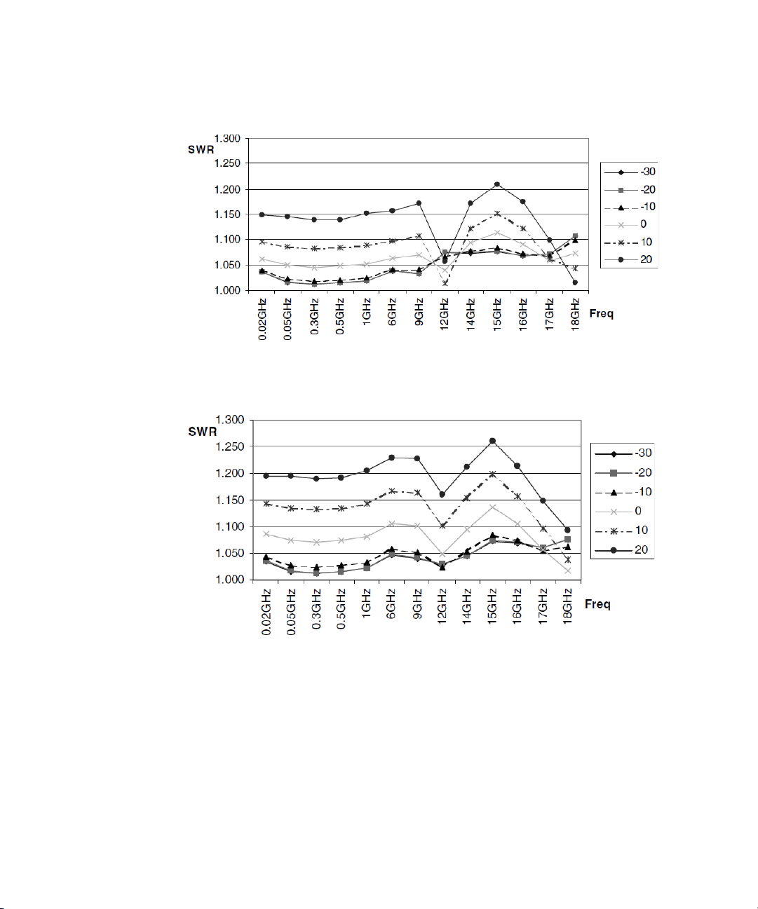
Figure 2-2 Typical SWR (50 MHz to 18 GHz) for the E9322A and E9326A
sensors at various power levels
Figure 2-3 Typical SWR (50 MHz to 18 GHz) for the E9323A and E9327A
sensors at various power levels
Keysight E9320 Operating and Service Guide 27
Page 24

2 Specifications and Characteristics
Sensor linearity
Tab le 2-7 Power sensor linearity normal mode (upper and lower range)
Sensor
E9321A
E9325A
E9322A
E9326A
E9323A
E9327A
Temperature
(25 ± 10 °C)
±4.2% ±5.0%
±4.2% ±5.0%
±4.2% ±5.0%
Temperature
(0 to 55 °C)
Tab le 2-8 Power sensor linearity average-only mode (upper and lower
range)
Sensor
E9321A
E9325A
E9322A
E9326A
E9323A
E9327A
Temperature
(25 ± 10 °C)
±3.7% ±4.5%
±3.7% ±4.5%
±3.7% ±5.0%
Temperature
(0 to 55 °C)
If the temperature changes after calibration and the meter and sensor are NOT
recalibrated, the following additional linearity errors (shown in Table 2-9) should
be added to the power linearity figures in Tab le 2- 7 and Table 2-8.
28 Keysight E9320 Operating and Service Guide
Page 25

Specifications and Characteristics 2
Table 2 -9 Additional linearity error (normal and average-only modes)
Sensor
E9321A
E9325A
E9322A
E9326A
E9323A
E9327A
Temperature
(25 ± 10 °C)
±1.0% ±1.0%
±1.0% ±1.5%
±1.0% ±2.0%
Temperature
(0 to 55 °C)
Figure 2-4 Typical power linearity at 25 °C for E9323A and E9327A 5 MHz
bandwid th sensors after zero and calibration, with associated
measurement uncertainty
Keysight E9320 Operating and Service Guide 29
Page 26

2 Specifications and Characteristics
Power range Measurement uncertainty
–30 to –20 dBm ±0.9%
–20 to –10 dBm ±0.89%
–10 to 0 dBm ±0.65%
0 to +10 dBm ±0.55%
+10 to +20 dBm ±0.45%
Figure 2-5 Relative mode power measurement linearity with an EPM-P
Series power meter, at 25 °C (typical)
Figure 2-5 shows the typical uncertainty in making a relative power measurement,
using the same power meter channel and the same power sensor to obtain the
reference and measured values. It also assumes that negligible change in
frequency and mismatch error occurs when transitioning from the power level
used as the reference to the power level measured.
30 Keysight E9320 Operating and Service Guide
Page 27

Peak flatness
The peak flatness is the flatness of a peak-to-average ratio measurement for
various tone separations for an equal magnitude two-tone RF input. Figure 2-6,
Figure 2-7, and Figure 2-8 refer to the relative error in peak-to-average
measurement as the tone separation is varied. The measurements were performed
at –10 dBm average power using an E9288A sensor cable.
Specifications and Characteristics 2
Figure 2-6 E9321A and E9325A error in peak-to-average measurements for
a two-tone input (high, medium, low, and off filters)
Keysight E9320 Operating and Service Guide 31
Page 28

2 Specifications and Characteristics
Figure 2-7 Filter responses for the E9322A and E9326A power sensors
(high, medium, low, and off)
Figure 2-8 Filter responses for the E9323A and E9327A power sensors
(high, medium, low, and off)
32 Keysight E9320 Operating and Service Guide
Page 29

Specifications and Characteristics 2
SWR 1 Rho+()1Rho–()⁄=
Calibration factor (CF) and reflection coefficient (Rho)
Calibration factor and reflection coefficient data (Rho) are provided at frequency
intervals on a data sheet included with the power sensor. This data is unique to
each sensor. If you have more than one sensor, match the serial number on the
data sheet with the serial number of the sensor you are using. The CF corrects for
the frequency response of the sensor. The EPM-P Series power meter
automatically reads the CF data stored in the sensor and uses it to make
corrections.
For power levels greater than 0 dBm, add to the calibration factor uncertainty
specification:
±0.1% per dB for E9321A and E9325A power sensors
±0.15% per dB for E9322A and E9326A power sensors
±0.2% per dB for E9323A and E9327A power sensors
Reflection coefficient (Rho) relates to the SWR according to the formula:
Typical CF data are listed in Table 2-10.
The uncertainty analysis for the calibration of the sensors was calculated in
accordance with the ISO Guide. The uncertainty data, reported on the calibration
certificate, is the expanded uncertainty with a 95% confidence level and a
coverage factor of 2.
Table 2-10 Cal factor uncertainty at 0.1 mW (–10 dBm)
Frequency
50 MHz Reference Reference
100 MHz ±1.8 ±2.0
300 MHz ±1.8 ±2.0
500 MHz ±1.8 ±2.0
800 MHz ±1.8 ±2.0
Uncertainty (%)
(25 ± 10 °C)
Uncertainty (%)
(0 to 55 °C)
Keysight E9320 Operating and Service Guide 33
Page 30

2 Specifications and Characteristics
Table 2-10 Cal factor uncertainty at 0.1 mW (–10 dBm) (continued)
Frequency
1.0 GHz ±2.1 ±2.3
1.2 GHz ±2.1 ±2.3
1.5 GHz ±2.1 ±2.3
2.0 GHz ±2.1 ±2.3
3.0 GHz ±2.1 ±2.3
4.0 GHz ±2.1 ±2.3
5.0 GHz ±2.1 ±2.3
6.0 GHz ±2.1 ±2.3
7.0 GHz ±2.3 ±2.5
9.0 GHz ±2.3 ±2.5
9.0 GHz ±2.3 ±2.5
11.0 GHz ±2.3 ±2.5
12.0 GHz ±2.3 ±2.5
13.0 GHz ±2.3 ±2.5
14.0 GHz ±2.5 ±2.8
15.0 GHz ±2.5 ±2.8
Uncertainty (%)
(25 ± 10 °C)
Uncertainty (%)
(0 to 55 °C)
16.0 GHz ±2.5 ±2.8
17.0 GHz ±2.5 ±2.8
18.0 GHz ±2.5 ±2.8
34 Keysight E9320 Operating and Service Guide
Page 31

Zero set
Specifications and Characteristics 2
This specification applies to a ZERO performed when the sensor input is not
connected to the POWER REFERENCE.
Table 2-11 Zero set
Sensor
E9321A
E9325A
E9322A
E9326A
E9323A
E9327A
Zero set
(normal mode)
5 nW 0.17 nW
19 nW 0.5 nW
60 nW 0.6 nW
(average-only mode)
Zero set
Keysight E9320 Operating and Service Guide 35
Page 32

2 Specifications and Characteristics
Zero drift and measurement noise
Table 2-12 Zero drift and measurement noise
Zero drift
Sensor
E9321A
E9325A
E9322A
E9326A
E9323A
E9327A
[a] Within 1 hour after zero set, at a constant temperature, after a 24 hour warm-up of the power meter.
[b] Measured over a one minute interval, at a constant temperature, two standard deviations, with averaging set to
1 (normal mode), 16 (for average-only mode, normal speed) and 32 (average-only mode, x2 speed).
[c] In Free run acquisition mode.
[d] Noise per sample, video bandwidth set to OFF with no averaging (i.e., averaging set to 1) - see Effect of video
bandwidth setting: and Tab le 2- 14.
Normal
mode
<
±5 nW
<
±5 nW
<
±40 nW
[a]
Average-onl y
mode
<
±60 pW
<
±100 pW
<
±100 pW
Normal
mode
<
6 nW
<
12 nW
<
25 nW
Measurement noise
[c]
Normal
mode
<
75 nW
<
180 nW
<
550 nW
[d]
[b]
Average-onl y
mode
<
165 pW
<
330 pW
<
400 pW
36 Keysight E9320 Operating and Service Guide
Page 33

Specifications and Characteristics 2
<6 nW 0.88× 1.2×()<6.34 nW=
Effect of averaging on noise: Averaging over 1 to 1024 readings is available
for reducing noise. Table 2-12 provides the measurement noise for a particular
sensor. Use the noise multipliers in Tab le 2-13 for the appropriate speed (normal
or x2), or measurement mode (normal and average-only), and the number of
averages to determine the total measurement noise value.
In addition, for x2 speed (in normal mode) the total measurement noise should be
multiplied by 1.2 and for fast speed (in normal mode) the multiplier is 3.4. Note
that in fast speed no additional averaging is implemented.
Table 2-13 Noise multipliers
Noise multiplier
Number of averages
1 5.5 6.5 1.0
2 3.89 4.6 0.94
4 2.75 3.25 0.88
8 1.94 2.3 0.82
16 1.0 1.63 0.76
32 0.85 1.0 0.70
64 0.61 0.72 0.64
128 0.49 0.57 0.58
256 0.34 0.41 0.52
512 0.24 0.29 0.46
1024 0.17 0.2 0.40
Average-onl y Normal
Normal speed x2 speed
Normal speed, free run
acquisition
Example: E9321A power sensor, number of averages = 4, free run acquisition,
normal mode, x2 speed.
Measurement noise calculation:
Keysight E9320 Operating and Service Guide 37
Page 34

2 Specifications and Characteristics
<180 nW 0.80×()<144 nW=
Effect of video bandwid th setting: The noise per sample is reduced by
applying the meter video bandwidth reduction filter setting (high, medium, or
low). If averaging is implemented, this will dominate any effect of changing the
video bandwidth.
Table 2-14 Effect of video bandwid th on noise per sample
Sensor
E9321A
E9325A
E9322A
E9326A
E9323A
E9327A
Low Medium High
0.32 0.5 0.63
0.50 0.63 0.80
0.40 0.63 1.0
Noise multipliers
Example: E9322A power sensor, triggered acquisition, high video bandwidth.
Noise per sample calculation:
Effect of time-gating on measurement noise: The measurement noise will
depend on the time gate length over which measurements are made. Effectively
20 averages are carried out every 1 μs of gate length.
38 Keysight E9320 Operating and Service Guide
Page 35

Settling times
Average-only mode
In normal and x2 speed, manual filter, 10 dB decreasing power step, refer to
Table 2-15.
Table 2-15 Averages vs. settling time (average-only mode)
Specifications and Characteristics 2
Number of averages
Normal speed x2 speed
1 0.08 0.07
2 0.13 0.09
4 0.24 0.15
8 0.45 0.24
16 1.1 0.45
32 1.9 1.1
64 3.5 1.9
128 6.7 3.5
256 14 6.7
512 27 14
1024 57 27
Settling time (s)
In fast mode, within the range –50 to +20 dBm, for a 10 dB decreasing power
step, the settling time is:
E4416A: 10 ms
E4417A: 20 ms
When a power step crosses the power sensor’s auto-range switch point, add
25 ms.
Keysight E9320 Operating and Service Guide 39
Page 36

2 Specifications and Characteristics
Normal mode
In normal, free run acquisition mode, within the range –20 to +20 dBm, for a
10 dB decreasing power step, the settling time is dominated by the measurement
update rate and is listed in Table 2-16 for various filter settings.
Table 2-16 Settling time vs. averages
Number of averages
1 0.1 0.08
2 0.15 0.1
4 0.25 0.15
8 0.45 0.25
16 0.9 0.45
32 1.7 0.9
64 3.3 1.7
128 6.5 3.3
256 13.0 6.5
Settling time (s)
Free run acquisition mode
Normal speed x2 speed
512 25.8 13.0
1024 51.5 25.8
In normal mode, measuring in continuous or single acquisition mode, the
performance of rise times, fall times and 99% settled results are shown in
Table 2-17. Rise and fall time specifications are for a 0.0 dBm pulse, with the rise
time and fall time measured between 10% to 90% points and upper range
selected.
40 Keysight E9320 Operating and Service Guide
Page 37

Specifications and Characteristics 2
Table 2-17 Rise and fall times vs. sensor band width
Sensor
E9321A
E9325A
E9322A
E9326A
E9323A
E9327A
Parameter Low Medium High Off
< μ
Rise time
Fall time
Settling time
(rising)
Settling time
(falling)
Rise time
Fall time
Settling time
(rising)
Settling time
(falling)
Rise time
Fall time
Settling time
(rising)
Settling time
(falling)
s 2.6 1.5 0.9 0.3
< μ
s 2.7 1.5 0.9 0.5
< μ
s
< μ
s
< μ
s 1.5 0.9 0.4 0.2
< μ
s 1.5 0.9 0.4 0.3
< μ
s
< μ
s
< μ
s0.9 0.4 0.2 0.2
< μ
s0.9 0.4 0.2 0.2
< μ
s
< μ
s
Video band width setting
5.1 5.1 4.5 0.6
5.1 5.1 4.5 0.9
5.3 4.5 3.5 0.5
5.3 4.5 3.5 0.9
4.5 3.5 1.5 0.4
4.5 3.5 2 0.4
[a]
[a] Rise and fall time specifications are only valid when used with the E9288A sensor cable (1.5 meters).
Overshoot in response to power steps with fast rise times, i.e., less than the sensor
rise time is less than 10%. When a power step crosses the power sensor’s
auto-range switch point, add 10 μs.
Keysight E9320 Operating and Service Guide 41
Page 38

2 Specifications and Characteristics
Physical specifications
Table 2-18 Physical specifications
Net weight 0.2 kg (0.45 lb)
Shipping weight 0.55 kg (1.2 lb)
Dimensions
Physical characteristics
Length: 150 mm (5.9 in)
Width: 38 mm (1.5 in)
Height: 30 mm (1.2 in)
42 Keysight E9320 Operating and Service Guide
Page 39

Keysight E9320 E-Series Peak and Average Power Sensors
Operating and Service Guide
3 Service
General Information 44
Performance Test 45
Service 58
Adjustments 62
This chapter introduces you to the general maintenance, performance tests,
troubleshooting, and repair of the E-Series E9320 power sensors.
43
Page 40

3Service
General Information
This chapter contains information about the general maintenance, performance
tests, troubleshooting, and repair of E-Series E9320 power sensors.
Cleaning
Use a clean, damp cloth to clean the body of the E-Series E9320 power sensor.
Connector cleaning
The RF connector beads deteriorate when contacted by hydrocarbon compounds
such as acetone, trichloroethylene, carbon tetrachloride, and benzene.
Clean the connector only at a static free workstation. Electrostatic discharge to
the center pin of the connector will render the power sensor inoperative.
Keeping in mind its flammable nature; a solution of pure isopropyl or ethyl alcohol
can be used to clean the connector.
Clean the connector face using a cotton swab dipped in isopropyl alcohol. If the
swab is too big use a round wooden toothpick wrapped in a lint free cotton cloth
dipped in isopropyl alcohol.
44 Keysight E9320 Operating and Service Guide
Page 41

Performance Test
Voltage standing wave ratio (VSWR) performance verification
VSWR is a measure of how efficiently radio frequency (RF) power is transmitted
from an RF power source. In real systems, mismatched impedances between the
RF source and load can cause some of the power to be reflected towards the
source and vary the VSWR.
This performance verification requires the following equipment:
– ENA Series Network Analyzer (E5071C)
– Calibration kit (85054B/D)
Procedure
1 Turn on the network analyzer and allow it to warm up for approximately an
hour.
2 Set the start frequency of the network analyzer to 50 MHz and the stop
frequency to one of the following:
Service 3
Table 3 -1 Stop frequency
Stop frequency Model
6 GHz E9321A, E9322A, and E9323A
18 GHz E9325A, E9326A, and E9327A
3 Calibrate the network analyzer using the appropriate calibration kit. Perform
calibration for the open, short, and load circuits of the network analyzer.
4 After calibration, connect the E-Series E9320 power sensor to the test port of
the network analyzer. Set the format for data trace to SWR.
5 Compare the measured results to the specifications in the data sheet. If the
verification fails, refer to “Adjustments” on page 62.
Keysight E9320 Operating and Service Guide 45
Page 42

3Service
Power linearity performance verification
The power linearity performance verification measures the relative linearity error
of the E-Series E9320 power sensor. All measurements are performed at 50 MHz.
The reference power level for the linearity measurement is 0 dBm for the E9321A,
E9322A, E9323A, E9325A, E9326A, and E9327A models.
This performance verification requires the following equipment:
– signal generator (N5182A)
– reference sensor (E4412A)
– power meter (E4416/7A)
– power splitter (11667A)
– amplifier
– step attenuators (8494H and 8496H)
– attenuator/switch driver (11713B)
Tab le 3-2 Linearity system verification specification
Sensor mode Power Specification
-30 dBm to 9 dBm ±5.50%
Average-only
10 dBm to 20 dBm ±6.73%
-30 dBm to 9 dBm ±5.96%
Normal
10 dBm to 20 dBm ±7.11%
Procedure
1 Turn on the signal generator and power meter (with the reference sensor
connected). Connect the DUT (E9320 E-Series power sensor) to channel A of
the power meter (E4416/7A), and channel B of the reference sensor (E4412A).
Allow them to warm up for approximately an hour.
2 Zero and calibrate both the DUT and reference sensor.
3 Connect the power splitter (11667A) to the RF output of the signal generator
(N5182A). The equipment setup is as shown in the following figure.
46 Keysight E9320 Operating and Service Guide
Page 43

Service 3
Signal generator
(Optional)
Amplifier
Power meter
DUT
Power splitter
Reference
sensor
Attenuator/
switch driver
10 dB step attenuator
1 dB step attenuator
CAUTION
Normalized P
ref
Measured power (P
ref
) Measured power at 0 dBm (P
ref
at 0 dBm)–=
Normalized P
DUT
Measured power (P
DUT
) Measured power at 0 dBm (P
DUT
at 0 dBm)–=
Figure 3-1 Power linearity performance verification equipment setup
4 Set the continuous wave signal frequency of the signal generator, DUT, and
reference sensor to 50 MHz. Set the DUT to average-only mode.
5 Start tuning the signal generator and/or optionally tune the attenuator or
switch driver until the DUT (channel A) measures the power level as close as
0 dBm. Record the values as P
at 0 dBm and P
DUT
at 0 dBm.
ref
Do not exceed the maximum input power (27 dBm) of the power splitter to
avoid damage to the power splitter.
6 Record the power measured by the power meter as P
P
for channel A.
DUT
7 Normalize both P
following equations:
Keysight E9320 Operating and Service Guide 47
and P
ref
to the power measured at 0 dBm, based on the
DUT
for channel B and as
ref
Page 44

3Service
Linearity error (dB) P
DUT
[]
norm to 0 dBm
P
ref
[]
norm to 0 dBm
–=
Linearity error (%) Ant i
P
DUT
[]
norm to 0 dBm
P
ref
[]
norm to 0 dBm
–
10
------------------------------------------ ----------------------- ------------------------ ---
1– 100
×
log=
Zero set performance verification
8 Calculate the linearity error of the DUT for the power level using the following
equations:
9 Compare the calculated linearity error to the system specifications. If the
verification fails, refer to “Adjustments” on page 62.
10 Repeat step 6 to step 9 by sweeping through the power levels from -30 dBm to
20 dBm with the same frequency of 50 MHz.
11 For the range of 16 to 20 dBm, add a 10 dB attenuator (8491B/8493C) before
the reference sensor and repeat step 5 to step 9 once.
12 Repeat step 5 to step 11 for normal mode.
48 Keysight E9320 Operating and Service Guide
This performance verification is carried out to verify that a minimal amount of
residual offset error is present after zeroing has been performed. The offset error is
caused by contamination from several sources including the noise of the DUT
itself. Zero set is the difference between the power levels indicated by the DUT,
after executing zeroing and the true zero power. Ideally, this difference should be
zero.
This performance verification requires the following equipment:
– power meter (E4416/7A)
Procedure
1 Connect the DUT (E-Series E9320 power sensor) to the power meter as shown
in the following figure.
Page 45

Service 3
DUT
Figure 3-2 Zero set performance verification equipment setup
2 Warm up the DUT for approximately 30 minutes.
3 Connect the DUT to the power meter reference oscilloscope to perform zero
and calibration.
4 Detach the DUT from the power meter reference oscilloscope.
5 Set the DUT to average-only mode.
6 Launch the Interactive IO on the Keysight IO Libraries Suite.
7 Set the frequency of the DUT to 50 MHz by sending “FREQ 50MHz”.
8 Enable auto-averaging for the DUT by sending “AVER:COUN:AUTO ON”.
9 Change the power measurement unit of the DUT to watt by sending
“UNIT:POW W”.
10 Set the DUT to the single trigger mode by sending “INIT:CONT OFF”.
11 Perform zeroing for the DUT by sending “CAL:ZERO:AUTO ONCE” and wait for
the power meter to complete the zeroing process.
12 Read the noise level of the DUT by sending “READ?” and then record the
reading.
13 Repeat 10 times, step 11 to step 12 and then calculate the mean value of the
readings.
14 Compare the calculated mean value to the system specification. If the
verification fails, refer to “Adjustments” on page 62.
15 Set DUT to normal mode. Repeat step 7 to step 14.
Keysight E9320 Operating and Service Guide 49
Page 46

3Service
Rise and fall time performance test
The rise and fall time performance of the instrument path must be quantified
accurately. This test however, is more of a system-level verification, validating the
rise and fall time using an actual RF pulse.
This performance verification requires the following equipment:
– Power meter (E4416/7A), E-Series E9320 power sensor, and sensor cable
(E9288A)
– Function generator (33611A)
– Signal generator (N5182B)
Procedure
1 Turn on the signal generator (N5182B), function generator (33611A), and
power meter (E4416/7A). Connect the E-Series E9320 power sensor (DUT) to
the power meter (E4416/7A) through the sensor cable (E9288A).
2 Allow the system to warm up for approximately an hour before starting the
measurement.
3 Set up the equipment as shown in the following figure.
50 Keysight E9320 Operating and Service Guide
Page 47

Service 3
Function generator (33611A)
Signal generator (N5182B)
Power meter (E4416/7A)
E-Series E9320 power sensor
Sensor Cable (E9288A)
OUTPUT
SYNC OUT
I INPUT
RF OUT
RF IN
TRIG IN
DUT
Keysight E9320 Operating and Service Guide 51
Figure 3-3 Rise and fall time performance test equipment setup
4 Perform sensor zero and calibration and connect the sensor to the signal
generator (N5182B) RF output port once completed.
5 Set the following for signal generator (N5182B):
– Turn on IQ state
– Set IQ modulator source to EXTERNAL
– Set frequency to 1 GHz
– Set power level to 0 dBm
6 Set the following for 33611A:
– Output a PULSE signal with frequency 10 kHz
– Set amplitude to 0.5Vpp and offset to 0.25V
– Set pulse width to 50us
Page 48

3Service
– Set pulse transition to 80ns
– Turn on output and synchronization
7 Set the following for power meter (E4416/7A):
– Set the following under Channel:
– Sensor Mode: NORMAL
–Range: UPPER
–Filter: OFF
–Offset: OFF
– Frequency: 1GHz
–FDO Table: OFF
–Video Avg: OFF
–Video B/W: OFF
– Step Detect: OFF
– Set the following under Channel, in trace setup:
–Start: 0 s
– Length: 2 μs
–Max: 1 mW
– Min: 1 nW
–Units: Watt
– Set the following under Trigger:
– Sensor Acqn A: single trigger
– Trigger source: EXT
– Set the following under Meas Setup, in Meas Select
Feed: Chan A, Gate 1, Meas Peak
– Set Meas Display in Disp Type to Trace
8 Turn on Mod On/Off and RF output on the signal generator (N5182B).
9 Trigger the sensor to capture the trace Trigger > Run.
52 Keysight E9320 Operating and Service Guide
Page 49
Service 3
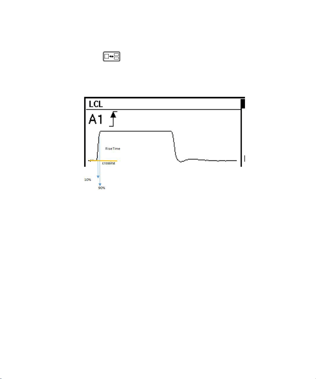
10 Press on the power meter front panel display to select the Gate Ctrl
menu.
11 Set Marker 1 to 10% crossing, then record its time as T1 and Marker 2 to 90%
crossing, then record its time as T2.
Figure 3-4 Rise time
12 Record the Rise Time = T2 - T1.
13 Change the E4416/7A trace setup start time to 50 μs.
14 Repeat step 7 to step 10.
Keysight E9320 Operating and Service Guide 53
Page 50

3Service
NOTE
Figure 3-5 Fall time
15 Record the Fall Time = T2 - T1.
16 Compare the Rise Time and Fall Time to the specifications in the data sheet.
Replaceable parts
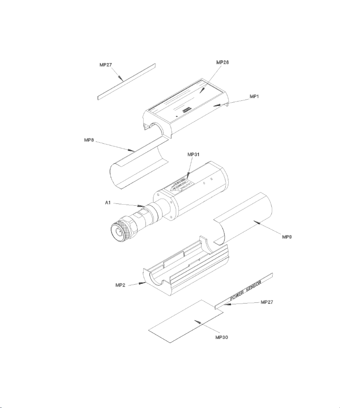
Table 3-3 is a list of replaceable parts. Figure 3-6 is the illustrated parts
breakdown that identifies all of the replaceable parts. To order a part, quote the
Keysight part number, specify the quantity required, and address the order to the
nearest Keysight office.
Within the USA, it is better to order directly from the Keysight Parts Center in
Roseville, California. Ask your nearest Keysight office for information and forms
for the “Direct Mail Order System.” Also your nearest Keysight office can supply
toll free telephone numbers for ordering parts and supplies.
54 Keysight E9320 Operating and Service Guide
Page 51
Service 3
Figure 3-6 Illustrated parts break down
Keysight E9320 Operating and Service Guide 55
Page 52

3Service
Tab le 3-3 Replaceable parts list
Reference designation Part number Qty Description
A1/A2
E9321A
A1/A2
E9321A
A1/A2
E9322A
A1/A2
E9322A
A1/A2
E9323A
A1/A2
E9323A
A1/A2
E9325A
A1/A2
E9325A
A1/A2
E9326A
A1/A2
E9326A
E9321-60011 1 SENSOR MODULE
E9321-60011 1
E9322-60004 1 SENSOR MODULE
E9322-60004 1
E9323-60002 1 SENSOR MODULE
E9323-60002 1
E9325-60002 1 SENSOR MODULE
E9325-60002 1
E9326-60002 1 SENSOR MODULE
E9326-60002 1
RESTORED SENSOR
MODULE
RESTORED SENSOR
MODULE
RESTORED SENSOR
MODULE
RESTORED SENSOR
MODULE
RESTORED SENSOR
MODULE
A1/A2
E9327A
A1/A2
E9327A
MP1 and MP2 E9321-40001 2 SHELL-PLASTIC
MP3 and MP4 E9321-20002 2 CHASSIS
MP8 and MP9 E9321-00001 2 SHIELD
MP26 E9321-80001 1 LABEL, ID E9321A
E9327-60002 1 SENSOR MODULE
E9327-60002 1
RESTORED SENSOR
MODULE
56 Keysight E9320 Operating and Service Guide
Page 53

Service 3
NOTE
Table 3 -3 Replaceable parts list (continued)
Reference designation Part number Qty Description
MP26 E9322-80001 1 LABEL, ID E9322A
MP26 E9323-80001 1 LABEL, ID E9323A
MP26 E9325-80001 1 LABEL, ID E9325A
MP26 E9326-80001 1 LABEL, ID E9326A
MP26 E9327-80001 1 LABEL, ID E9327A
MP27 E9321-80002 2
MP30 E9321-80003 1 LABEL, CAL/ESD
LABEL, POWER
SENSOR
The A1/A2 parts are applicable only for the Keysight Service Center as
calibration is required.
Keysight E9320 Operating and Service Guide 57
Page 54

3Service
Service
Principles of operation
Service instructions consist of principles of operation, troubleshooting, and
repairs.
The power sensor ‘bulkhead’ assembly converts input RF to a low frequency
voltage signal representing the RF power envelope. The input is AC coupled to a
3 dB attenuator followed by a 50 ohm load resistor. Two diodes are connected to
the load resistor, forming a pair of half-wave detectors with opposite polarity and
complementary voltage output. The detected signal passes through a low-pass
load filter. The cutoff frequency of the filter is 300 kHz, 1.5 MHz, or 5 MHz,
depending on the model/ bandwidth specification of the sensor.
The detected signal can now follow one of two paths. The average-only signal
path is optimized for high sensitivity and low drift at the expense of detector video
bandwidth. This path chops the signal to a carrier frequency around 440 Hz to
remove sensitivity to DC offsets, then amplifies the AC signal. Amplification and
chopping parameters are much the same as in previous Keysight diode sensors,
with typical dynamic power range of –65 to +20 dBm.
The chopper is a switch that connects the two balanced signals to the two inputs
of a differential amplifier. Thus, the small DC signal from the detector is converted
to an AC signal. The output of the differential amplifier is connected to a switched
gain preamplifier.
The dynamic range of the sensor is greater than 80 dB in this mode, so the sensor
has two power ranges. On the high power range the signal is attenuated before
further amplification. The bandwidth of the chopped signal is limited to less than
half the chop rate. So, this method cannot be used for wide (~5 MHz) bandwidth
measurements.
The normal path is used to detect the instantaneous power of an RF signal and is
optimized for a bandwidth of up to 5 MHz. The peak path trade off includes
reduced dynamic range and increased temperature sensitivity.
58 Keysight E9320 Operating and Service Guide
Page 55

Service 3
Figure 3-7 Simplified sensor block diagram
The output of the load filter is connected to a gain selectable amplifier with a
bandwidth corresponding to the sensor model/ bandwidth spec. The differential
configuration minimizes sensitivity to ground noise, DC offset and drift. In normal
mode, the amplifier provides maximum bandwidths of 300 kHz, 1.5 MHz, or
5 MHz, allowing the user to match the test signal’s modulation bandwidth to the
sophisticated instrument data processing. This permits the meter to measure
burst average and peak power, to compute peak-to-average ratios, and display
other time-gated power profiles on the power meter's large LCD screen.
The three dimensional calibration data is stored in an EEPROM on the sensor PCA.
This data is unique to each sensor and consists of frequency vs. input power vs.
temperature. Upon power-up, or when the sensor cable is connected, these
calibration factors are downloaded into the EPM-P (E4416A/17A) Series power
meters. This means that the operator is not required to enter any calibration
information when changing sensors, simply entering the frequency of the input
signal is all that is required.
Keysight E9320 Operating and Service Guide 59
Page 56

3Service
Troubleshooting
Repair of defective sensor
Troubleshooting information is intended to first isolate the power sensor, cable, or
power meter as the defective component. When the power sensor is isolated, an
appropriate sensor module must be used for repair. See Tab le 3-3.
If error message 241 or 310 is displayed on the power meter, suspect a power
sensor failure. Error 241 will occur if the sensor is missing. An E9288 cable must
be used to connect an E-Series E9320 power sensor to an EPM-P Series power
meter.
If no error message is displayed, but a problem occurs when making a
measurement, try replacing the cable from the power meter to the power sensor.
If the problem still exists, try using a different power sensor to determine if the
problem is in the power meter or in the power sensor.
Electrostatic discharge will render the power sensor inoperative. Do not, under
any circumstances, open the power sensor unless you and the power sensor are in
a static free environment.
There are no serviceable parts inside the E-Series E9320 power sensors. If the
sensor is defective, replace the entire “module” with the appropriate “Restored
Sensor Module” listed in Tab le 3-3.
60 Keysight E9320 Operating and Service Guide
Page 57
Disassembly procedure
Disassemble the power sensor by performing the following steps:
1 Disassemble the power sensor only in a static free workstation. Electrostatic
discharge renders the power sensor inoperative.
Service 3
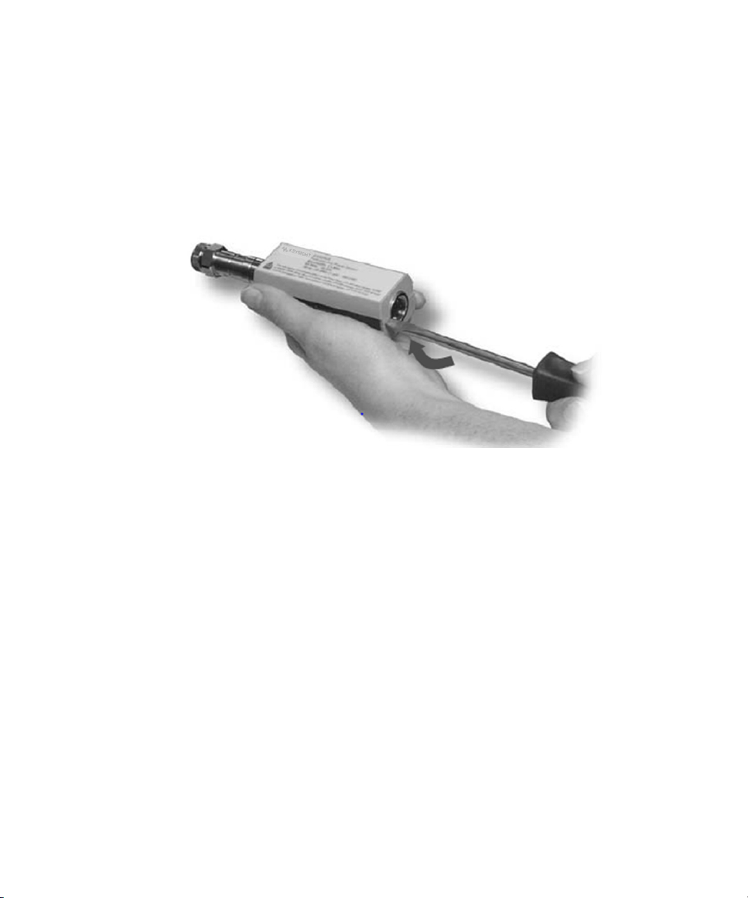
Figure 3-8 Removing the power sensor shell
2 At the rear of the power sensor, insert the blade of a screwdriver between the
plastic shells (See Figure 3-8). To prevent damage to the plastic shells use a
screwdriver blade as wide as the slot between the two shells.
3 Pry alternately at both sides of the connector J1 until the plastic shells are
apart. Remove the shells and the magnetic shields.
Reassembly procedure
Replace the magnetic shields and the plastic shells. Snap the plastic shells
together.
Keysight E9320 Operating and Service Guide 61
Page 58

3Service
Adjustments
Adjustments are usually required on a yearly basis. They are normally performed
only after a performance verification has indicated that some parameters are out
of specification. Performance verification must be completed after any repairs that
may have altered the characteristics of the E-Series E9320 power sensors.
The E-Series E9320 power sensors can be adjusted using the Keysight N7800
Series calibration software or can be returned to Keysight for adjustments. To
arrange the return, contact the Keysight Service Center.
62 Keysight E9320 Operating and Service Guide
Page 59

This information is subject to change
without notice. Always refer to the
Keysight website for the latest
revision.
© Keysight Technologies 2003 - 2017
Edition 8, May 26, 2017
Printed in Malaysia
*E9321-90001*
E9321-90001
 Loading...