

Page 1

75000 Series C
User and Service Manual
Keysight E8402A, E8404A
VXI Mainframes
Page 2

Page 3

Notices
© Keysight Technologies, Inc. 1997-2019
No part of this manual may be reproduced in any form or by any means
(including electronic storage and retrieval
or translation into a foreign language)
without prior agreement and written consent from Keysight Technologies, Inc. as
governed by United States and international copyright laws.
Manual Part Number
E8402-90002
Edition
Third Edition, October 2019
Published by
Keysight Technologies, Inc.
900 S. Taft Ave.
Loveland, CO 80537 USA
Sales and Technical Support
To contact Keysight for sales and technical support, refer to the support links on
the following Keysight websites:
www.keysight.com/find/E8402A
(product-specific information and support, software and documentation
updates)
www.keysight.com/find/assist (world-
wide contact information for repair and
service)
Declaration of Conformity
Declarations of Conformity for this product and for other Keysight products may
be downloaded from the Web. Go to
http://keysight.com/go/conformity and
click on “Declarations of Conformity.” You
can then search by product number to
find the latest Declaration of Conformity.
Technology Licenses
The hardware and/or software described
in this document are furnished under a
license and may be used or copied only in
accordance with the terms of such
license.
Warranty
THE MATERIAL CONTAINED IN THIS
DOCUMENT IS PROVIDED “AS IS,” AND
IS SUBJECT TO BEING CHANGED,
WITHOUT NOTICE, IN FUTURE EDITIONS. FURTHER, TO THE MAXIMUM
EXTENT PERMITTED BY APPLICABLE
LAW, KEYSIGHT DISCLAIMS ALL WARRANTIES, EITHER EXPRESS OR IMPLIED,
WITH REGARD TO THIS MANUAL AND
ANY INFORMATION CONTAINED
HEREIN, INCLUDING BUT NOT LIMITED
TO THE IMPLIED WARRANTIES OF MERCHANTABILITY AND FITNESS FOR A
PARTICULAR PURPOSE. KEYSIGHT
SHALL NOT BE LIABLE FOR ERRORS OR
FOR INCIDENTAL OR CONSEQUENTIAL
DAMAGES IN CONNECTION WITH THE
FURNISHING, USE, OR PERFORMANCE
OF THIS DOCUMENT OR OF ANY INFORMATION CONTAINED HEREIN. SHOULD
KEYSIGHT AND THE USER HAVE A SEPARATE WRITTEN AGREEMENT WITH
WARRANTY TERMS COVERING THE
MATERIAL IN THIS DOCUMENT THAT
CONFLICT WITH THESE TERMS, THE
WARRANTY TERMS IN THE SEPARATE
AGREEMENT SHALL CONTROL.
Keysight Technologies does not warrant
third-party system-level (combination of
chassis, controllers, modules, etc.) performance, safety, or regulatory compliance unless specifically stated.
DFARS/Restricted Rights
Notices
If software is for use in the performance
of a U.S. Government prime contract or
subcontract, Software is delivered and
licensed as “Commercial computer software” as defined in DFAR 252.227-7014
(June 1995), or as a “commercial item” as
defined in FAR 2.101(a) or as “Restricted
computer software” as defined in FAR
52.227-19 (June 1987) or any equivalent
agency regulation or contract clause.
Use, duplication or disclosure of Software
is subject to Keysight Technologies’ standard commercial license terms, and nonDOD Departments and Agencies of the
U.S. Government will receive no greater
than Restricted Rights as defined in FAR
52.227-19(c)(1-2) (June 1987). U.S. Government users will receive no greater
than Limited Rights as defined in FAR
52.227-14 (June 1987) or DFAR 252.2277015 (b)(2) (November 1995), as applicable in any technical data.
Page 4

Safety Information
The following general safety precautions must be observed during all
phases of operation of this instrument.
Failure to comply with these precautions or with specific warnings or operating instructions in the product
manuals violates safety standards of
design, manufacture, and intended use
of the instrument. Keysight Technologies assumes no liability for the customer's failure to comply with these
requirements.
General
Do not use this product in any manner not
specified by the manufacturer. The protective features of this product must not be
impaired if it is used in a manner specified in
the operation instructions.
Before Applying Power
Verify that all safety precautions are taken.
Make all connections to the unit before
applying power. Note the external markings
described under “Safety Symbols”.
Ground the Instrument
Keysight chassis’ are provided with a
grounding-type power plug. The
instrument chassis and cover must be
connected to an electrical ground to
minimize shock hazard. The ground pin
must be firmly connected to an electrical ground (safety ground) terminal at
the power outlet. Any interruption of
the protective (grounding) conductor
or disconnection of the protective
earth terminal will cause a potential
shock hazard that could result in personal injury.
Do Not Operate in an Explosive
Atmosphere
Do not operate the module/chassis in
the presence of flammable gases or
fumes.
Do Not Operate Near Flammable
Liquids
Do not operate the module/chassis in
the presence of flammable liquids or
near containers of such liquids.
Cleaning
Clean the outside of the Keysight module/chassis with a soft, lint-free,
slightly dampened cloth. Do not use
detergent or chemical solvents.
Do Not Remove Instrument Cover
Only qualified, service-trained personnel who are aware of the hazards
involved should remove instrument
covers. Always disconnect the power
cable and any external circuits before
removing the instrument cover.
Keep away from live circuits
Operating personnel must not remove
equipment covers or shields. Procedures involving the removal of covers
and shields are for use by servicetrained personnel only. Under certain
conditions, dangerous voltages may
exist even with the equipment
switched off. To avoid dangerous electrical shock, DO NOT perform procedures involving cover or shield removal
unless you are qualified to do so.
DO NOT operate damaged
equipment
Whenever it is possible that the safety
protection features built into this product have been impaired, either through
physical damage, excessive moisture,
or any other reason, REMOVE POWER
and do not use the product until safe
operation can be verified by servicetrained personnel. If necessary, return
the product to a Keysight Technologies
Sales and Service Office for service and
repair to ensure the safety features are
maintained.
DO NOT block the primary
disconnect
The primary disconnect device is the
appliance connector/power cord when
a chassis used by itself, but when
installed into a rack or system the disconnect may be impaired and must be
considered part of the installation.
Do Not Modify the Instrument
Do not install substitute parts or perform any unauthorized modification to
the product. Return the product to a
Keysight Sales and Service Office to
ensure that safety features are maintained.
In Case of Damage
Instruments that appear damaged or
defective should be made inoperative
and secured against unintended operation until they can be repaired by
qualified service personnel
Do NOT block vents and fan exhaust:
To ensure adequate cooling and ventilation, leave a gap of at least 50mm
(2") around vent holes on both sides of
the chassis.
Do NOT operate with empty slots: To
ensure proper cooling and avoid damaging equipment, fill each empty slot
with an AXIe filler panel module.
Do NOT stack free-standing chassis:
Stacked chassis should be rackmounted.
All modules are grounded through the
chassis: During installation, tighten
each module's retaining screws to
secure the module to the chassis and
to make the ground connection.
Operator is responsible to maintain
safe operating conditions. To ensure
safe operating conditions, modules
should not be operated beyond the full
temperature range specified in the
Environmental and physical specification. Exceeding safe operating conditions can result in shorter lifespan,
improper module performance and
user safety issues. When the modules
are in use and operation within the
specified full temperature range is not
maintained, module surface temperatures may exceed safe handling conditions which can cause discomfort or
burns if touched. In the event of a
module exceeding the full temperature
range, always allow the module to cool
before touching or removing modules
from the chassis.
iv
Page 5

Safety Symbols
A CAUTION denotes a hazard. It
calls attention to an operating procedure or practice, that, if not correctly performed or adhered to
could result in damage to the
product or loss of important data.
Do not proceed beyond a CAUTION
notice until the indicated conditions are fully understood and met.
A WARNING denotes a hazard. It
calls attention to an operating procedure or practice, that, if not correctly performed or adhered to,
could result in personal injury or
death. Do not proceed beyond a
WARNING notice until the indicated conditions are fully understood and met.
Products display the following symbols:
Warning, risk of electric
shock
Refer to manual for additional safety information.
Earth Ground.
Chassis Ground.
Alternating Current (AC).
Direct Current (DC)
v
Page 6

vi
Page 7

Contents
1 Getting Started
Product Overview . . . . . . . . . . . . . . . . . . . . . . . . . . . . . . . . . . . . . . . . . . . . . . . . 15
Preparing Your VXI System for Use . . . . . . . . . . . . . . . . . . . . . . . . . . . . . . . . . . 16
AC Power Requirements . . . . . . . . . . . . . . . . . . . . . . . . . . . . . . . . . . . . . . . . 16
Positioning the Mainframe for Adequate Cooling . . . . . . . . . . . . . . . . . . . . 16
Connecting the Mainframe to a Permanent Earth Ground . . . . . . . . . . . . . 17
Installing VXI Instruments . . . . . . . . . . . . . . . . . . . . . . . . . . . . . . . . . . . . . . . . . 19
Installing C-Size Instruments . . . . . . . . . . . . . . . . . . . . . . . . . . . . . . . . . . . . 20
Installing A- and B-Size Instruments . . . . . . . . . . . . . . . . . . . . . . . . . . . . . . 21
Configuring Your Mainframe . . . . . . . . . . . . . . . . . . . . . . . . . . . . . . . . . . . . . . . 22
Setting the Enhanced Monitor VXI Logical Address . . . . . . . . . . . . . . . . . . 22
RS-232 Interface. . . . . . . . . . . . . . . . . . . . . . . . . . . . . . . . . . . . . . . . . . . . . . 23
External +5V Supply . . . . . . . . . . . . . . . . . . . . . . . . . . . . . . . . . . . . . . . . . . . 23
Using the Remote Power-On Pins . . . . . . . . . . . . . . . . . . . . . . . . . . . . . . . . 24
Disabling the On/Stdby Switch . . . . . . . . . . . . . . . . . . . . . . . . . . . . . . . . . . 25
Mainframe Options and Accessories . . . . . . . . . . . . . . . . . . . . . . . . . . . . . . . . . 26
2 Using the Enhanced Monitor
Using the Enhanced Monitor . . . . . . . . . . . . . . . . . . . . . . . . . . . . . . . . . . . . . . . 29
Using the Display . . . . . . . . . . . . . . . . . . . . . . . . . . . . . . . . . . . . . . . . . . . . . 31
Enhanced Monitor Fan Control . . . . . . . . . . . . . . . . . . . . . . . . . . . . . . . . . . . . . 35
Software Control of Fan Speed. . . . . . . . . . . . . . . . . . . . . . . . . . . . . . . . . . . 35
Setting Enhanced Monitor Limits . . . . . . . . . . . . . . . . . . . . . . . . . . . . . . . . . . . 37
Temperature Limits . . . . . . . . . . . . . . . . . . . . . . . . . . . . . . . . . . . . . . . . . . . . 37
Current and Power Limits . . . . . . . . . . . . . . . . . . . . . . . . . . . . . . . . . . . . . . . 37
Handling Warnings . . . . . . . . . . . . . . . . . . . . . . . . . . . . . . . . . . . . . . . . . . . . 38
Save The Limits . . . . . . . . . . . . . . . . . . . . . . . . . . . . . . . . . . . . . . . . . . . . . . . 38
Enhanced Monitor Measurement Cycles. . . . . . . . . . . . . . . . . . . . . . . . . . . . . . 39
Using the History Queue . . . . . . . . . . . . . . . . . . . . . . . . . . . . . . . . . . . . . . . . . . 40
HISTory Queue . . . . . . . . . . . . . . . . . . . . . . . . . . . . . . . . . . . . . . . . . . . . . . . 40
RS-232 Programming . . . . . . . . . . . . . . . . . . . . . . . . . . . . . . . . . . . . . . . . . . . . 41
Diagnostic Connector . . . . . . . . . . . . . . . . . . . . . . . . . . . . . . . . . . . . . . . . . . . . 43
+5VC (pin 6). . . . . . . . . . . . . . . . . . . . . . . . . . . . . . . . . . . . . . . . . . . . . . . . . . 44
+12VC (pin 7). . . . . . . . . . . . . . . . . . . . . . . . . . . . . . . . . . . . . . . . . . . . . . . . . 44
+5V STDBY (pins 8, 21). . . . . . . . . . . . . . . . . . . . . . . . . . . . . . . . . . . . . . . . . 44
SYSRESET* (pin 10). . . . . . . . . . . . . . . . . . . . . . . . . . . . . . . . . . . . . . . . . . . . 44
ACFAIL* (pin 23) . . . . . . . . . . . . . . . . . . . . . . . . . . . . . . . . . . . . . . . . . . . . . . 44
Keysight E1406A User Manual and SCPI Programming Guide vii
Page 8

3 Programming the Enhanced Monitor
Understanding SCPI Commands. . . . . . . . . . . . . . . . . . . . . . . . . . . . . . . . . . . . 45
Common Command Format . . . . . . . . . . . . . . . . . . . . . . . . . . . . . . . . . . . . . 45
SCPI Command Format . . . . . . . . . . . . . . . . . . . . . . . . . . . . . . . . . . . . . . . . 45
Command Separator. . . . . . . . . . . . . . . . . . . . . . . . . . . . . . . . . . . . . . . . . . . 46
Abbreviated Commands . . . . . . . . . . . . . . . . . . . . . . . . . . . . . . . . . . . . . . . . 46
Implied Commands . . . . . . . . . . . . . . . . . . . . . . . . . . . . . . . . . . . . . . . . . . . . 46
Parameters . . . . . . . . . . . . . . . . . . . . . . . . . . . . . . . . . . . . . . . . . . . . . . . . . . 47
Programming Examples . . . . . . . . . . . . . . . . . . . . . . . . . . . . . . . . . . . . . . . . . . . 48
Example 1: Self Test & Verification . . . . . . . . . . . . . . . . . . . . . . . . . . . . . . . . 49
Example 2: Setting up the Mainframe . . . . . . . . . . . . . . . . . . . . . . . . . . . . . 51
Example 3: Set-up the RS-232. . . . . . . . . . . . . . . . . . . . . . . . . . . . . . . . . . . 54
Example 4: Reading Current Status Information . . . . . . . . . . . . . . . . . . . . . 56
SCPI Command Reference. . . . . . . . . . . . . . . . . . . . . . . . . . . . . . . . . . . . . . . . . 60
CALibration Subsystem . . . . . . . . . . . . . . . . . . . . . . . . . . . . . . . . . . . . . . . . . . . 60
Subsystem Syntax. . . . . . . . . . . . . . . . . . . . . . . . . . . . . . . . . . . . . . . . . . . . . 60
DISPlay Subsystem . . . . . . . . . . . . . . . . . . . . . . . . . . . . . . . . . . . . . . . . . . . . . . 60
Subsystem Syntax. . . . . . . . . . . . . . . . . . . . . . . . . . . . . . . . . . . . . . . . . . . . . 60
DISPlay[:WINDow] <display window>
DISPlay[:WINDow]?. . . . . . . . . . . . . . . . . . . . . . . . . . . . . . . . . . . . . . . . . . . . 61
DISPlay[:WINDow]:STATe <state>
DISPlay[:WINDow]:STATe? . . . . . . . . . . . . . . . . . . . . . . . . . . . . . . . . . . . . . . 65
DISPlay[:WINDow]:TEXT[:DATA] <string>. . . . . . . . . . . . . . . . . . . . . . . . . . . 66
FORMat Subsystem . . . . . . . . . . . . . . . . . . . . . . . . . . . . . . . . . . . . . . . . . . . . . . 68
Subsystem Syntax. . . . . . . . . . . . . . . . . . . . . . . . . . . . . . . . . . . . . . . . . . . . . 68
FORMat:BORDer <order>
FORMat:BORDer? . . . . . . . . . . . . . . . . . . . . . . . . . . . . . . . . . . . . . . . . . . . . . 68
HISTory Subsystem . . . . . . . . . . . . . . . . . . . . . . . . . . . . . . . . . . . . . . . . . . . . . . 69
Subsystem Syntax. . . . . . . . . . . . . . . . . . . . . . . . . . . . . . . . . . . . . . . . . . . . . 69
HISTory:BLOWer[:HISTogram]? <blower>[,MIN|MAX] . . . . . . . . . . . . . . . . . 70
HISTory:CURRent:CMAXimum? <supply> . . . . . . . . . . . . . . . . . . . . . . . . . . 72
HISTory:CURRent[:HISTogram]? <supply>[,MIN|MAX]. . . . . . . . . . . . . . . . . 73
HISTory:CURRent:MAXimum? <supply> . . . . . . . . . . . . . . . . . . . . . . . . . . . 75
HISTory:POWer:CMAXimum? <supply> . . . . . . . . . . . . . . . . . . . . . . . . . . . . 76
HISTory:POWer[:HISTogram]? <supply>[,MIN|MAX] . . . . . . . . . . . . . . . . . . 77
HISTory:POWer:MAXimum? <supply> . . . . . . . . . . . . . . . . . . . . . . . . . . . . . 79
HISTory:QUEue:COUNt? . . . . . . . . . . . . . . . . . . . . . . . . . . . . . . . . . . . . . . . . 81
HISTory:QUEue[:FETCh]? <event index>. . . . . . . . . . . . . . . . . . . . . . . . . . . . 82
HISTory:RESet[:ALL]
HISTory:RESet:BLOWer [<blower>]
HISTory:RESet:CURRent [<supply>]
HISTory:RESet:POWer [<supply>]
HISTory:RESet:QUEue
HISTory:RESet:TEMPerature [<slot>]
HISTory:RESet:VOLTage [<supply>] . . . . . . . . . . . . . . . . . . . . . . . . . . . . . . . 85
viii Keysight E1406A User Manual and SCPI Programming Guide
Page 9

HISTory:TEMPerature:CMAXimum? <slot>
HISTory:TEMPerature:CMINimum? <slot> . . . . . . . . . . . . . . . . . . . . . . . . . . 87
HISTory:TEMPerature[:HISTogram]? <slot>[,MIN|MAX] . . . . . . . . . . . . . . . . 89
HISTory:TEMPerature:MAXimum? <slot>
HISTory:TEMPerature:MINimum? <slot> . . . . . . . . . . . . . . . . . . . . . . . . . . . 91
HISTory:TIME:LCALibration?. . . . . . . . . . . . . . . . . . . . . . . . . . . . . . . . . . . . . 93
HISTory:TIME:LHReset? . . . . . . . . . . . . . . . . . . . . . . . . . . . . . . . . . . . . . . . . 94
HISTory:TIME:LTST? . . . . . . . . . . . . . . . . . . . . . . . . . . . . . . . . . . . . . . . . . . . 95
HISTory:TIME:ON? . . . . . . . . . . . . . . . . . . . . . . . . . . . . . . . . . . . . . . . . . . . . 96
HISTory:TIME:OPERating? . . . . . . . . . . . . . . . . . . . . . . . . . . . . . . . . . . . . . . 97
HISTory:UNIT[:TIME] <unit>
HISTory:UNIT[:TIME]? . . . . . . . . . . . . . . . . . . . . . . . . . . . . . . . . . . . . . . . . . . 98
HISTory:VOLTage:CMAXimum? <supply>
HISTory:VOLTage:CMINimum? <supply> . . . . . . . . . . . . . . . . . . . . . . . . . . 100
HISTory:VOLTage[:HISTogram]? <supply>[,MIN|MAX] . . . . . . . . . . . . . . . . 101
HISTory:VOLTage:MAXimum? <supply>
HISTory:VOLTage:MINimum? <supply> . . . . . . . . . . . . . . . . . . . . . . . . . . . 103
STATus Subsystem. . . . . . . . . . . . . . . . . . . . . . . . . . . . . . . . . . . . . . . . . . . . . . 105
Subsystem Syntax . . . . . . . . . . . . . . . . . . . . . . . . . . . . . . . . . . . . . . . . . . . 107
STATus:OPERation:CONDition? . . . . . . . . . . . . . . . . . . . . . . . . . . . . . . . . . 109
STATus:OPERation:ENABle <mask>
STATus:OPERation:ENABle? . . . . . . . . . . . . . . . . . . . . . . . . . . . . . . . . . . . . 111
STATus:OPERation:EVENt?. . . . . . . . . . . . . . . . . . . . . . . . . . . . . . . . . . . . . 113
STATus:PRESet . . . . . . . . . . . . . . . . . . . . . . . . . . . . . . . . . . . . . . . . . . . . . . 114
STATus:QUEStionable:BLOWer:CONDition? . . . . . . . . . . . . . . . . . . . . . . . 115
STATus:QUEStionable:BLOWer:ENABle <mask>
STATus:QUEStionable:BLOWer:ENABle? . . . . . . . . . . . . . . . . . . . . . . . . . . 117
STATus:QUEStionable:BLOWer:EVENt? . . . . . . . . . . . . . . . . . . . . . . . . . . . 119
STATus:QUEStionable:BLOWer:LEVel?. . . . . . . . . . . . . . . . . . . . . . . . . . . . 120
STATus:QUEStionable:BLOWer:SPEed? <blower>[,MIN|MAX] . . . . . . . . . 121
STATus:QUEStionable:CONDition?. . . . . . . . . . . . . . . . . . . . . . . . . . . . . . . 122
STATus:QUEStionable:CURRent:CONDition?. . . . . . . . . . . . . . . . . . . . . . . 124
STATus:QUEStionable:CURRent:ENABle <mask>
STATus:QUEStionable:CURRent:ENABle? . . . . . . . . . . . . . . . . . . . . . . . . . 126
STATus:QUEStionable:CURRent[:EVENt]? . . . . . . . . . . . . . . . . . . . . . . . . . 128
STATus:QUEStionable:CURRent:LEVel? <supply>[,MIN|MAX]. . . . . . . . . . 129
STATus:QUEStionable:CURRent:LIMit <supply>,<value>
STATus:QUEStionable:CURRent:LIMit? <supply> [,MIN|MAX]. . . . . . . . . . 131
STATus:QUEStionable:ENABle <mask>
STATus:QUEStionable:ENABle? . . . . . . . . . . . . . . . . . . . . . . . . . . . . . . . . . 133
STATus:QUEStionable[:EVENt]? . . . . . . . . . . . . . . . . . . . . . . . . . . . . . . . . . 135
STATus:QUEStionable:POWer:LEVel? <supply>[,MIN|MAX] . . . . . . . . . . . 136
STATus:QUEStionable:POWer:LIMit <limit>
STATus:QUEStionable:POWer:LIMit? [MIN|MAX] . . . . . . . . . . . . . . . . . . . . 137
STATus:QUEStionable:TEMPerature:CONDition?. . . . . . . . . . . . . . . . . . . . 138
STATus:QUEStionable:TEMPerature:ENABle <mask>
STATus:QUEStionable:TEMPerature:ENABle? . . . . . . . . . . . . . . . . . . . . . . 140
STATus:QUEStionable:TEMPerature:EVENt? . . . . . . . . . . . . . . . . . . . . . . . 142
STATus:QUEStionable:TEMPerature:LEVel? <slot>[,MIN|MAX] . . . . . . . . . 143
Keysight E1406A User Manual and SCPI Programming Guide ix
Page 10

STATus:QUEStionable:TEMPerature:LIMit
<slot>,<value1>[,<value2>[,<value3>]]
STATus:QUEStionable:TEMPerature:LIMit? <slot>[,MIN|MAX]. . . . . . . . . . 144
STATus:QUEStionable:UMCounter:TINTerval <time>
STATus:QUEStionable:UMCounter:TINTerval? . . . . . . . . . . . . . . . . . . . . . . 146
STATus:QUEStionable:UMCounter:TREMaining? . . . . . . . . . . . . . . . . . . . . 147
STATus:QUEStionable:UMCounter:TRESet. . . . . . . . . . . . . . . . . . . . . . . . . 148
STATus:QUEStionable:VOLTage:CONDition? . . . . . . . . . . . . . . . . . . . . . . . 149
STATus:QUEStionable:VOLTage:ENABle <mask>
STATus:QUEStionable:VOLTage:ENABle? . . . . . . . . . . . . . . . . . . . . . . . . . . 151
STATus:QUEStionable:VOLTage:EVENt?. . . . . . . . . . . . . . . . . . . . . . . . . . . 153
STATus:QUEStionable:VOLTage:LEVel? <supply>[,MIN|MAX] . . . . . . . . . . 154
STATus:QUEStionable:VOLTage:PTR <mask>
STATus:QUEStionable:VOLTage:PTR?. . . . . . . . . . . . . . . . . . . . . . . . . . . . . 155
STATus:SCONdition? . . . . . . . . . . . . . . . . . . . . . . . . . . . . . . . . . . . . . . . . . . 157
SYSTem Subsystem . . . . . . . . . . . . . . . . . . . . . . . . . . . . . . . . . . . . . . . . . . . . . 159
Subsystem Syntax. . . . . . . . . . . . . . . . . . . . . . . . . . . . . . . . . . . . . . . . . . . . 159
SYSTem:BEEPer:FREQuency <frequency>
SYSTem:BEEPer:FREQuency? [MIN | MAX] . . . . . . . . . . . . . . . . . . . . . . . . 161
SYSTem:BEEPer[:IMMediate] [<frequency>[,<duration>]] . . . . . . . . . . . . . 162
SYSTem:BEEPer:STATe <state>
SYSTem:BEEPer:STATe? . . . . . . . . . . . . . . . . . . . . . . . . . . . . . . . . . . . . . . . 163
SYSTem:BEEPer:TIME <duration>
SYSTem:BEEPer:TIME? . . . . . . . . . . . . . . . . . . . . . . . . . . . . . . . . . . . . . . . . 164
SYSTem:BLOWer:STATe <state>
SYSTem:BLOWer:STATe?. . . . . . . . . . . . . . . . . . . . . . . . . . . . . . . . . . . . . . . 165
SYSTem:COMMunicate:SERial:CONTrol:RTS <rts>
SYSTem:COMMunicate:SERial:CONTrol:RTS? . . . . . . . . . . . . . . . . . . . . . . 167
SYSTem:COMMunicate:SERial:ECHO <echo>
SYSTem:COMMunicate:SERial:ECHO?. . . . . . . . . . . . . . . . . . . . . . . . . . . . 168
SYSTem:COMMunicate:SERial:ERESponse <eresponse>
SYSTem:COMMunicate:SERial:ERESponse? . . . . . . . . . . . . . . . . . . . . . . . 169
SYSTem:COMMunicate:SERial:LBUFfer <lbuffer>
SYSTem:COMMunicate:SERial:LBUFfer? . . . . . . . . . . . . . . . . . . . . . . . . . . 170
SYSTem:COMMunicate:SERial:PRESet[:ALL]
SYSTem:COMMunicate:SERial:PRESet:RAW
SYSTem:COMMunicate:SERial:PRESet:TERMinal . . . . . . . . . . . . . . . . . . . 171
SYSTem:COMMunicate:SERial[:RECeive]:BAUD <baud>|MIN|MAX|DEF
SYSTem:COMMunicate:SERial[:RECeive]:BAUD?. . . . . . . . . . . . . . . . . . . . 172
SYSTem:COMMunicate:SERial[:RECeive]:BITS <bits>
SYSTem:COMMunicate:SERial[:RECeive]:BITS?. . . . . . . . . . . . . . . . . . . . . 173
SYSTem:COMMunicate:SERial[:RECeive]:PACE <pace>
SYSTem:COMMunicate:SERial[:RECeive]:PACE? . . . . . . . . . . . . . . . . . . . . 175
SYSTem:COMMunicate:SERial[:RECeive]:PARity[:TYPE] <parity>
SYSTem:COMMunicate:SERial[:RECeive]:PARity[:TYPE]? . . . . . . . . . . . . . 176
SYSTem:COMMunicate:SERial[:RECeive]:SBITs <bits>
SYSTem:COMMunicate:SERial[:RECeive]:SBITs? [MIN|MAX|DEF] . . . . . . . 178
SYSTem:COMMunicate:VXI:ADDRess? <address>. . . . . . . . . . . . . . . . . . . 180
SYSTem:DATE:LMAintenance? . . . . . . . . . . . . . . . . . . . . . . . . . . . . . . . . . . 181
SYSTem:ERRor?. . . . . . . . . . . . . . . . . . . . . . . . . . . . . . . . . . . . . . . . . . . . . . 182
x Keysight E1406A User Manual and SCPI Programming Guide
Page 11

SYSTem:HELP:HEADers? . . . . . . . . . . . . . . . . . . . . . . . . . . . . . . . . . . . . . . 183
SYSTem:MODel?. . . . . . . . . . . . . . . . . . . . . . . . . . . . . . . . . . . . . . . . . . . . . 184
SYSTem:NAME <name>
SYSTem:NAME? . . . . . . . . . . . . . . . . . . . . . . . . . . . . . . . . . . . . . . . . . . . . . 185
SYSTem:NVDefault . . . . . . . . . . . . . . . . . . . . . . . . . . . . . . . . . . . . . . . . . . . 187
SYSTem:NVRecall. . . . . . . . . . . . . . . . . . . . . . . . . . . . . . . . . . . . . . . . . . . . 189
SYSTem:NVSave . . . . . . . . . . . . . . . . . . . . . . . . . . . . . . . . . . . . . . . . . . . . . 190
SYSTem:POWer <state>
SYSTem:POWer?. . . . . . . . . . . . . . . . . . . . . . . . . . . . . . . . . . . . . . . . . . . . . 192
SYSTem:POWer:CYCLe? . . . . . . . . . . . . . . . . . . . . . . . . . . . . . . . . . . . . . . . 194
SYSTem:POWer:SOURce? . . . . . . . . . . . . . . . . . . . . . . . . . . . . . . . . . . . . . 195
SYSTem:POWer:STATus? . . . . . . . . . . . . . . . . . . . . . . . . . . . . . . . . . . . . . . 196
SYSTem:SNUMber <string>
SYSTem:SNUMber? . . . . . . . . . . . . . . . . . . . . . . . . . . . . . . . . . . . . . . . . . . 197
SYSTem:VERSion? . . . . . . . . . . . . . . . . . . . . . . . . . . . . . . . . . . . . . . . . . . . 199
TEST Subsystem . . . . . . . . . . . . . . . . . . . . . . . . . . . . . . . . . . . . . . . . . . . . . . . 200
Subsystem Syntax . . . . . . . . . . . . . . . . . . . . . . . . . . . . . . . . . . . . . . . . . . . 200
TEST[:ALL]?. . . . . . . . . . . . . . . . . . . . . . . . . . . . . . . . . . . . . . . . . . . . . . . . . 201
TEST:BLOWer? [<blower>] . . . . . . . . . . . . . . . . . . . . . . . . . . . . . . . . . . . . . 203
TEST:DISPlay?. . . . . . . . . . . . . . . . . . . . . . . . . . . . . . . . . . . . . . . . . . . . . . . 205
TEST:MEMory? . . . . . . . . . . . . . . . . . . . . . . . . . . . . . . . . . . . . . . . . . . . . . . 206
TEST:RESults[:CODE]? . . . . . . . . . . . . . . . . . . . . . . . . . . . . . . . . . . . . . . . . 207
TEST:RESults:VERBose? [<code>] . . . . . . . . . . . . . . . . . . . . . . . . . . . . . . . 208
TEST:SENSe? . . . . . . . . . . . . . . . . . . . . . . . . . . . . . . . . . . . . . . . . . . . . . . . 209
TEST:TEMPerature? . . . . . . . . . . . . . . . . . . . . . . . . . . . . . . . . . . . . . . . . . . 210
TEST:TIME?. . . . . . . . . . . . . . . . . . . . . . . . . . . . . . . . . . . . . . . . . . . . . . . . . 211
TRACe Subsystem . . . . . . . . . . . . . . . . . . . . . . . . . . . . . . . . . . . . . . . . . . . . . . 212
Subsystem Syntax . . . . . . . . . . . . . . . . . . . . . . . . . . . . . . . . . . . . . . . . . . . 212
TRACe[:DATA]? <name> . . . . . . . . . . . . . . . . . . . . . . . . . . . . . . . . . . . . . . . 213
TRACe[:DATA]:PREamble? <name> . . . . . . . . . . . . . . . . . . . . . . . . . . . . . . 215
TRACe:POINts? <name>. . . . . . . . . . . . . . . . . . . . . . . . . . . . . . . . . . . . . . . 217
IEEE Common Commands . . . . . . . . . . . . . . . . . . . . . . . . . . . . . . . . . . . . . . . 218
*CLS . . . . . . . . . . . . . . . . . . . . . . . . . . . . . . . . . . . . . . . . . . . . . . . . . . . . . . 219
*ESE <mask>
*ESE?. . . . . . . . . . . . . . . . . . . . . . . . . . . . . . . . . . . . . . . . . . . . . . . . . . . . . . 220
*ESR? . . . . . . . . . . . . . . . . . . . . . . . . . . . . . . . . . . . . . . . . . . . . . . . . . . . . . 222
*IDN?. . . . . . . . . . . . . . . . . . . . . . . . . . . . . . . . . . . . . . . . . . . . . . . . . . . . . . 223
*OPC
*OPC? . . . . . . . . . . . . . . . . . . . . . . . . . . . . . . . . . . . . . . . . . . . . . . . . . . . . . 224
*PSC
*PSC? . . . . . . . . . . . . . . . . . . . . . . . . . . . . . . . . . . . . . . . . . . . . . . . . . . . . . 225
*RST . . . . . . . . . . . . . . . . . . . . . . . . . . . . . . . . . . . . . . . . . . . . . . . . . . . . . . 227
*SRE <mask>
*SRE? . . . . . . . . . . . . . . . . . . . . . . . . . . . . . . . . . . . . . . . . . . . . . . . . . . . . . 228
*STB?. . . . . . . . . . . . . . . . . . . . . . . . . . . . . . . . . . . . . . . . . . . . . . . . . . . . . . 230
*TST?. . . . . . . . . . . . . . . . . . . . . . . . . . . . . . . . . . . . . . . . . . . . . . . . . . . . . . 232
Keysight E1406A User Manual and SCPI Programming Guide xi
Page 12

*WAI. . . . . . . . . . . . . . . . . . . . . . . . . . . . . . . . . . . . . . . . . . . . . . . . . . . . . . . 233
SCPI Command Quick Reference . . . . . . . . . . . . . . . . . . . . . . . . . . . . . . . . . . 234
Common Command Quick Reference . . . . . . . . . . . . . . . . . . . . . . . . . . . . . . . 242
4 Calibrating and Verifying Performance
Recommended Test Equipment. . . . . . . . . . . . . . . . . . . . . . . . . . . . . . . . . . . . 243
Functional Verification . . . . . . . . . . . . . . . . . . . . . . . . . . . . . . . . . . . . . . . . . . . 243
Procedure . . . . . . . . . . . . . . . . . . . . . . . . . . . . . . . . . . . . . . . . . . . . . . . . . . 244
Calibration and Performance Verification . . . . . . . . . . . . . . . . . . . . . . . . . . . . 245
Test Conditions & Procedures . . . . . . . . . . . . . . . . . . . . . . . . . . . . . . . . . . . 245
Issuing Commands . . . . . . . . . . . . . . . . . . . . . . . . . . . . . . . . . . . . . . . . . . . 245
Temperature Monitor Calibration & Verification. . . . . . . . . . . . . . . . . . . . . 245
Calibration Procedure . . . . . . . . . . . . . . . . . . . . . . . . . . . . . . . . . . . . . . . . . 246
Verification Procedure. . . . . . . . . . . . . . . . . . . . . . . . . . . . . . . . . . . . . . . . . 247
Voltage Monitor Calibration & Verification . . . . . . . . . . . . . . . . . . . . . . . . . 247
Calibration Procedure . . . . . . . . . . . . . . . . . . . . . . . . . . . . . . . . . . . . . . . . . 248
Verification Procedure. . . . . . . . . . . . . . . . . . . . . . . . . . . . . . . . . . . . . . . . . 249
Timer Test Verification. . . . . . . . . . . . . . . . . . . . . . . . . . . . . . . . . . . . . . . . . 249
Performance Test Record. . . . . . . . . . . . . . . . . . . . . . . . . . . . . . . . . . . . . . . . . 250
Test Equipment Used: . . . . . . . . . . . . . . . . . . . . . . . . . . . . . . . . . . . . . . . . . 250
CALibration Subsystem . . . . . . . . . . . . . . . . . . . . . . . . . . . . . . . . . . . . . . . . . . 253
Subsystem Syntax. . . . . . . . . . . . . . . . . . . . . . . . . . . . . . . . . . . . . . . . . . . . 253
CALibration[:ALL]?. . . . . . . . . . . . . . . . . . . . . . . . . . . . . . . . . . . . . . . . . . . . 253
CALibration:TEMPerature? . . . . . . . . . . . . . . . . . . . . . . . . . . . . . . . . . . . . . 255
CALibration:VALue:TEMPerature <value>
CALibration:VALue:TEMPerature? . . . . . . . . . . . . . . . . . . . . . . . . . . . . . . . 257
CALibration:VALue:VOLTage <supply>,<value>
CALibration:VALue:VOLTage? <supply> . . . . . . . . . . . . . . . . . . . . . . . . . . . 259
CALibration:VOLTage?. . . . . . . . . . . . . . . . . . . . . . . . . . . . . . . . . . . . . . . . . 261
5 Servicing Your Mainframe
Chapter Overview. . . . . . . . . . . . . . . . . . . . . . . . . . . . . . . . . . . . . . . . . . . . . . . 263
Problem Isolation . . . . . . . . . . . . . . . . . . . . . . . . . . . . . . . . . . . . . . . . . . . . . . . 263
No Power Line Fuse . . . . . . . . . . . . . . . . . . . . . . . . . . . . . . . . . . . . . . . . . . 263
Replacing Assemblies . . . . . . . . . . . . . . . . . . . . . . . . . . . . . . . . . . . . . . . . . . . 265
Removing the Rear Panel from the Mainframe . . . . . . . . . . . . . . . . . . . . . 265
Removing the Mainframe Cover . . . . . . . . . . . . . . . . . . . . . . . . . . . . . . . . . 267
Replacing the Internal Temperature Sensor Boards . . . . . . . . . . . . . . . . . 268
Replacing the Enhanced Monitor Controller Board . . . . . . . . . . . . . . . . . . 269
Replacing the Keysight E8402A Power Supply . . . . . . . . . . . . . . . . . . . . . 270
Replacing the Keysight E8404A Power Supply . . . . . . . . . . . . . . . . . . . . . 271
Replacing the Impeller . . . . . . . . . . . . . . . . . . . . . . . . . . . . . . . . . . . . . . . . 272
xii Keysight E1406A User Manual and SCPI Programming Guide
Page 13

Replacing the Enhanced Monitor Display Lamp . . . . . . . . . . . . . . . . . . . . 273
Replacement Power Cords . . . . . . . . . . . . . . . . . . . . . . . . . . . . . . . . . . . . . . . 274
A Keysight E8402, E8404A Product Specifications
Product Descriptions . . . . . . . . . . . . . . . . . . . . . . . . . . . . . . . . . . . . . . . . . . . . 277
General Specifications . . . . . . . . . . . . . . . . . . . . . . . . . . . . . . . . . . . . . . . . 277
Mechanical Specifications . . . . . . . . . . . . . . . . . . . . . . . . . . . . . . . . . . . . . 277
Output Power Specifications. . . . . . . . . . . . . . . . . . . . . . . . . . . . . . . . . . . . . . 278
Total Available and Usable Power . . . . . . . . . . . . . . . . . . . . . . . . . . . . . . . 278
Peak and Dynamic Current. . . . . . . . . . . . . . . . . . . . . . . . . . . . . . . . . . . . . 278
Output Voltage Specifications . . . . . . . . . . . . . . . . . . . . . . . . . . . . . . . . . . 278
Input Power Requirements . . . . . . . . . . . . . . . . . . . . . . . . . . . . . . . . . . . . . . . 279
Mains Power Installation Category II . . . . . . . . . . . . . . . . . . . . . . . . . . . . . 280
Cooling Specifications. . . . . . . . . . . . . . . . . . . . . . . . . . . . . . . . . . . . . . . . . . . 280
Cooling Specification Charts . . . . . . . . . . . . . . . . . . . . . . . . . . . . . . . . . . . 280
Cooling Mode (High or Variable) . . . . . . . . . . . . . . . . . . . . . . . . . . . . . . . . 281
Airflow Path . . . . . . . . . . . . . . . . . . . . . . . . . . . . . . . . . . . . . . . . . . . . . . . . 282
Acoustical Noise Specifications . . . . . . . . . . . . . . . . . . . . . . . . . . . . . . . . . . . 282
Backplane Specifications . . . . . . . . . . . . . . . . . . . . . . . . . . . . . . . . . . . . . . . . 282
General Monitor Specifications. . . . . . . . . . . . . . . . . . . . . . . . . . . . . . . . . . . . 282
Indicators . . . . . . . . . . . . . . . . . . . . . . . . . . . . . . . . . . . . . . . . . . . . . . . . . . 282
Switches . . . . . . . . . . . . . . . . . . . . . . . . . . . . . . . . . . . . . . . . . . . . . . . . . . . 283
Diagnostic Connector. . . . . . . . . . . . . . . . . . . . . . . . . . . . . . . . . . . . . . . . . 283
Enhanced Monitor Specifications . . . . . . . . . . . . . . . . . . . . . . . . . . . . . . . . . . 284
Temperature Monitor . . . . . . . . . . . . . . . . . . . . . . . . . . . . . . . . . . . . . . . . . 284
Voltage Monitor . . . . . . . . . . . . . . . . . . . . . . . . . . . . . . . . . . . . . . . . . . . . . 284
Current Monitor . . . . . . . . . . . . . . . . . . . . . . . . . . . . . . . . . . . . . . . . . . . . . 285
Power Monitor . . . . . . . . . . . . . . . . . . . . . . . . . . . . . . . . . . . . . . . . . . . . . . 285
Fan Speed Monitor . . . . . . . . . . . . . . . . . . . . . . . . . . . . . . . . . . . . . . . . . . . 285
Timer . . . . . . . . . . . . . . . . . . . . . . . . . . . . . . . . . . . . . . . . . . . . . . . . . . . . . . 285
Front Panel Display. . . . . . . . . . . . . . . . . . . . . . . . . . . . . . . . . . . . . . . . . . . 285
VXIbus Interface . . . . . . . . . . . . . . . . . . . . . . . . . . . . . . . . . . . . . . . . . . . . . 285
RS232 Interface . . . . . . . . . . . . . . . . . . . . . . . . . . . . . . . . . . . . . . . . . . . . . 286
Environmental Specifications . . . . . . . . . . . . . . . . . . . . . . . . . . . . . . . . . . . . . 287
Temperature . . . . . . . . . . . . . . . . . . . . . . . . . . . . . . . . . . . . . . . . . . . . . . . . 287
Safety Specifications . . . . . . . . . . . . . . . . . . . . . . . . . . . . . . . . . . . . . . . . . 287
Electromagnetic Compliance Specifications . . . . . . . . . . . . . . . . . . . . . . . 288
Power Supply Protection . . . . . . . . . . . . . . . . . . . . . . . . . . . . . . . . . . . . . . 289
Repair . . . . . . . . . . . . . . . . . . . . . . . . . . . . . . . . . . . . . . . . . . . . . . . . . . . . . 289
Keysight E1406A User Manual and SCPI Programming Guide xiii
Page 14

B Rack Mounting and Option Installation
Chapter Overview. . . . . . . . . . . . . . . . . . . . . . . . . . . . . . . . . . . . . . . . . . . . . . . 291
Rack Mounting the Keysight E840xA Mainframe . . . . . . . . . . . . . . . . . . . . . . 291
Parts List . . . . . . . . . . . . . . . . . . . . . . . . . . . . . . . . . . . . . . . . . . . . . . . . . . . 292
Rack Mounting the Keysight E840xA using Support Rails. . . . . . . . . . . . . 293
Procedure . . . . . . . . . . . . . . . . . . . . . . . . . . . . . . . . . . . . . . . . . . . . . . . . . . 293
Rack Mounting the Keysight E840xA Using Rack Slide Rails . . . . . . . . . . 297
Installing the Cable Tray . . . . . . . . . . . . . . . . . . . . . . . . . . . . . . . . . . . . . . . . . 302
Parts List . . . . . . . . . . . . . . . . . . . . . . . . . . . . . . . . . . . . . . . . . . . . . . . . . . . 302
Procedure . . . . . . . . . . . . . . . . . . . . . . . . . . . . . . . . . . . . . . . . . . . . . . . . . . 302
Installing the Tinted Acrylic Door (Option 915). . . . . . . . . . . . . . . . . . . . . . . . 305
Parts List . . . . . . . . . . . . . . . . . . . . . . . . . . . . . . . . . . . . . . . . . . . . . . . . . . . 305
Procedure . . . . . . . . . . . . . . . . . . . . . . . . . . . . . . . . . . . . . . . . . . . . . . . . . . 305
Installing the Intermodule Chassis Shields . . . . . . . . . . . . . . . . . . . . . . . . . . . 307
Parts List . . . . . . . . . . . . . . . . . . . . . . . . . . . . . . . . . . . . . . . . . . . . . . . . . . . 307
Procedure . . . . . . . . . . . . . . . . . . . . . . . . . . . . . . . . . . . . . . . . . . . . . . . . . . 307
Installing the Backplane Connector Shields . . . . . . . . . . . . . . . . . . . . . . . . . . 309
Parts List . . . . . . . . . . . . . . . . . . . . . . . . . . . . . . . . . . . . . . . . . . . . . . . . . . . 309
Procedure . . . . . . . . . . . . . . . . . . . . . . . . . . . . . . . . . . . . . . . . . . . . . . . . . . 310
Keysight E840xA Air Filter Kit . . . . . . . . . . . . . . . . . . . . . . . . . . . . . . . . . . . . . 311
xiv Keysight E1406A User Manual and SCPI Programming Guide
Page 15

Keysight E8402A, E8404A C-Size Mainframes
User and Service Guide
1 Getting Started
This chapter contains general information on the operating features of the
E8402A and E8404A C-Size VXI mainframes. The following table lists the major
differences between these two mainframes:
Unless otherwise specifically noted, descriptions in this manual relate to both VXI
mainframes. The designation Keysight E840xA refers to both mainframes.
Chapter 2 provides a complete Enhanced Monitor description.
Product Overview
The Keysight E840xA VXI mainframes are designed in full compliance with
VXIbus specification revision 1.4, VXIplug&play specification VPP-8, and VMEbus
system specification revision C.1. Additional features of the Keysight E840xA
mainframes include:
– Mainframe monitoring of:
Power Supply
500 W 1000 W
Keysight E8402A Mainframe ü ü
Keysight E8404A Mainframe ü ü
-- backplane voltage conditions
-- individual slot and power supply temperatures
Enhanced
Monitor
-- fan and impeller operation
– State of the art cooling technology:
-- quiet, variable speed power supply fan and backplane impeller
-- increased static pressure
– Front panel Diagnostic Connector for:
-- power supply voltage measurements
-- power supply and backplane temperature measurements
-- power supply fan and backplane impeller verification
15
Page 16

Getting Started Preparing Your VXI System for Use
– Color Graphical Enhanced Monitor Display:
-- Help messages localized in English, French, German, Spanish
-- Stripcharts and Histograms for easy diagnostics
-- Three Temperature sensors per mainframe slot
-- Display of each power supply voltage or current
-- User text messages
– Easy maintenance:
-- rear panel access to power supply, power supply fan, and cooling
impeller for either bench or rack mount operation.
Preparing Your VXI System for Use
The Keysight E840xA mainframes are shipped from the factory ready to use. This
section describes important mainframe installation procedures.
AC Power Requirements
The Keysight E840xA mainframes can be operated at line voltages of
90 VAC to 264 VAC, and line frequencies of 47 Hz to 66 Hz. The mainframe can
also operate at 360 Hz to 440 Hz with line voltages of
90 VAC to 132 VAC.
The mainframes ship with a power cord and with a fast blow fuse installed. The
fuse is suitable for all line voltages. The fuse is not user replaceable. Refer to
“Replacement Power Cords” on page 274 for additional information on E840xA
power cords and on fuse replacement. Appendix A contains complete input
power specifications.
The power cord is the only way to disconnect the mainframe
from AC power and, therefore, it must be accessible to the
operator at all times. When the Keysight E840xA mainframes
are mounted in a system cabinet, the power cord need not be
accessible since the cabinet must have its own disconnect
device.
Positioning the Mainframe for Adequate Cooling
VXI instruments are cooled by air drawn through the back of the mainframe and
exhausted out the sides. The power supply is cooled by air drawn from the right
side (facing the mainframe) and exhausted out the left side. When placing the
mainframe on a work bench or if the mainframe is rack mounted, provide at least
a one inch clearance at the back and sides to allow for proper air flow.
16 Keysight E8402A, E8404A C-Size Mainframes User and Service Guide
Page 17
Preparing Your VXI System for Use Getting Started
TOOTHED
WASHERS
BACK COVER
WIRE LUG
GREEN WIRE
WITH YELLOW
STRIPE
PERMA NENT EA RTH
GROUND CONNECTION
LOCATION
Air filters are not necessary on these mainframes. However, an optional air filter
kit (mainframe option 938 or Keysight E8401-80938) is available for use in harsh
environments. The airflow is restricted less than 10% with the air filter installed.
Refer to “Keysight E840xA Air Filter Kit” on page 311 for installation information.
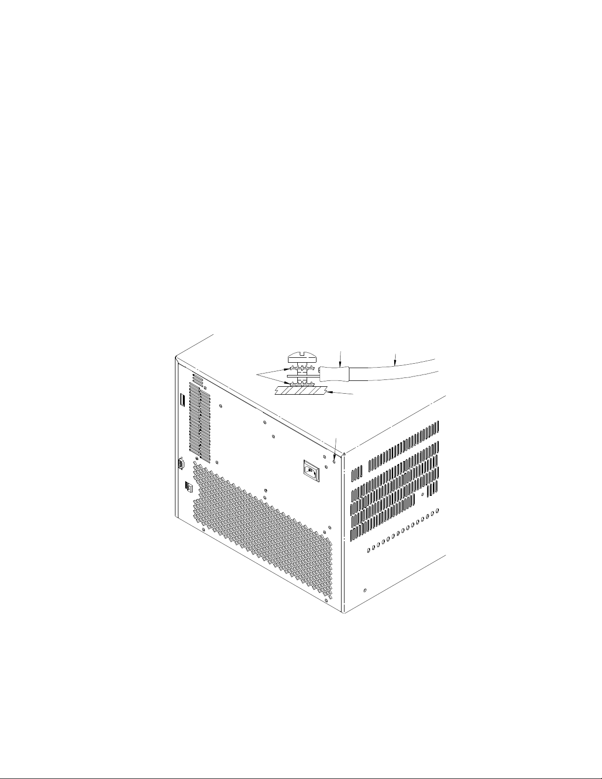
Connecting the Mainframe to a Permanent Earth Ground
The mainframe must be connected to a permanent earth ground for line
frequencies greater than 66 Hz. This connection is made on the back of the
mainframe:
1 Connect a 16 AWG (1.3 mm or larger) wire to the PEM nut shown in Figure 1.
The wire must be green with a yellow stripe, or bare (no insulation). Use a m4
x 10 screw, grounding lug, and toothed washers (or toothed lug) as shown in
the figure below.
2 Attach the other end of the wire to a permanent earth ground using toothed
washers or a toothed lug.
Figure 1-1 Connecting an Keysight E840xA Mainframe to a Permanent Earth Ground
(Keysight E8404 shown, Keysight E8402 is similar)
Keysight E8402A, E8404A C-Size Mainframes User and Service Guide 17
Page 18

Getting Started Preparing Your VXI System for Use
For protection from electrical shock when operating at
frequencies greater than 66 Hz, connect the chassis ground
terminal to permanent earth ground.
AVERTISSEMENT
Risque de Choch èlectrique. Si la frèquence du secteur est
supèrieure à 66 Hz, relier la borne de masse du chassis à
une prise de terre fixe.
18 Keysight E8402A, E8404A C-Size Mainframes User and Service Guide
Page 19

Installing VXI Instruments Getting Started
Installing VXI Instruments
The Keysight E840xA mainframes have 13 slots labeled 0 through 12. Any VXI
instrument can be installed in any slot; however, slot 0 is reserved for devices
capable of providing the system’s slot 0 functionality. This functionality includes:
– locating instruments installed in the mainframe
– managing (arbitrating) data flow across the backplane
– providing the system clock (SYSCLK - 16 MHz)
Examples of these devices are the Keysight E1406 Command Module and
embedded controllers such as the Keysight E623x series VXI Pentium PCs, the
Keysight RADEPC7B PC, and the Keysight E1497/E1498 V743 controllers.
Multiple instruments which combine to create a virtual instrument (e.g. a
scanning multimeter), and instruments which access the backplane local bus
should be installed in adjacent slots.
1 To prevent damage to the VXI instruments, turn off the mainframe prior to
installing the instruments.
2 Insert the instrument into the mainframe by aligning the instrument with the
card guides inside the mainframe. Slowly push the instrument into the slot
until it seats in the backplane connectors. The front panel of the instrument
should be even with the front edges of the mainframe.
3 Tighten the retaining screws on the top and bottom of the module.
All instruments within the VXI mainframe are grounded
through the mainframe chassis. During installation, tighten
the instrument's retaining screws to secure the instrument
to the mainframe and to make the ground connection.
Keysight E8402A, E8404A C-Size Mainframes User and Service Guide 19
Page 20
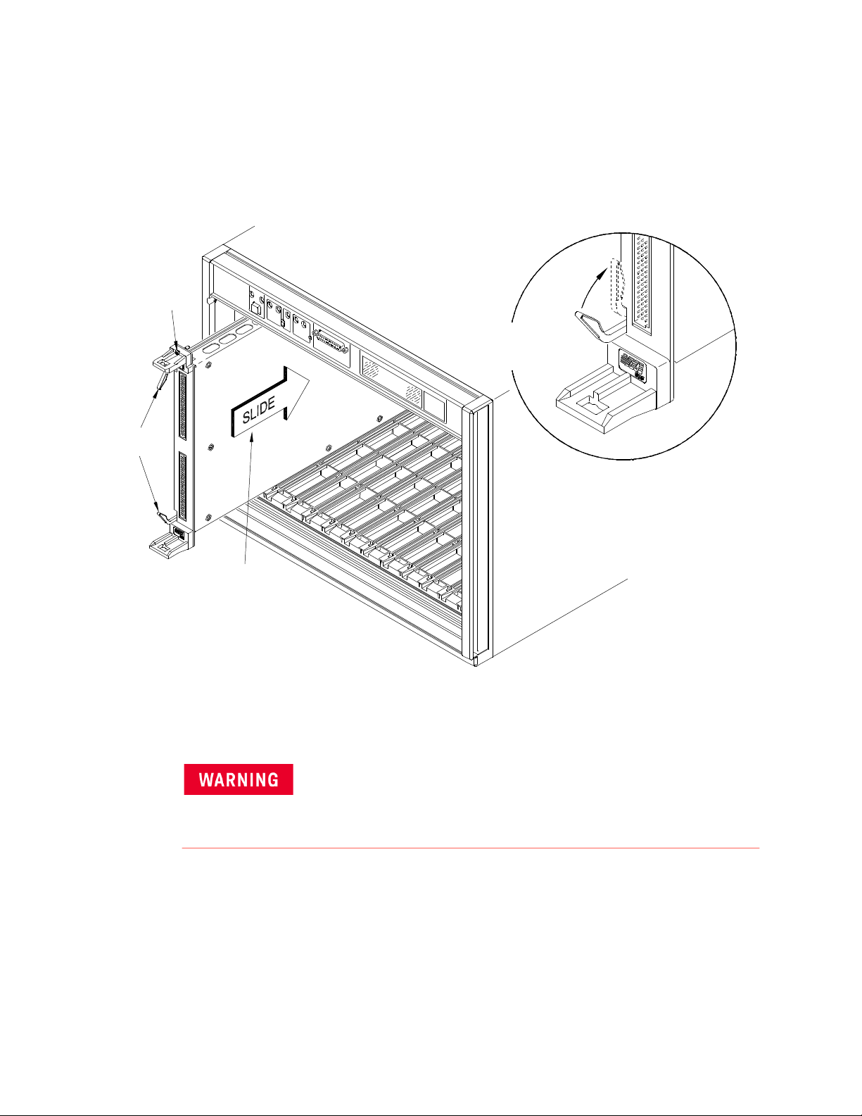
Getting Started Installing VXI Instruments
Retaining
Screws
Extraction
Levers
Slide the module
into the mainframe
until it plugs into the
backplane connectors
Seat the module by
pushing in the
extraction levers
Installing C-Size Instruments
Figure 2 shows the installation of C-Size instruments.
Figure 1-2 Installing C-Size Instruments in the Keysight E840xA Mainframe
All instruments within the VXI mainframe are grounded
through the mainframe chassis. During installation, tighten
the instrument's retaining screws to secure the instrument
to the mainframe and to make the ground connection.
20 Keysight E8402A, E8404A C-Size Mainframes User and Service Guide
Page 21
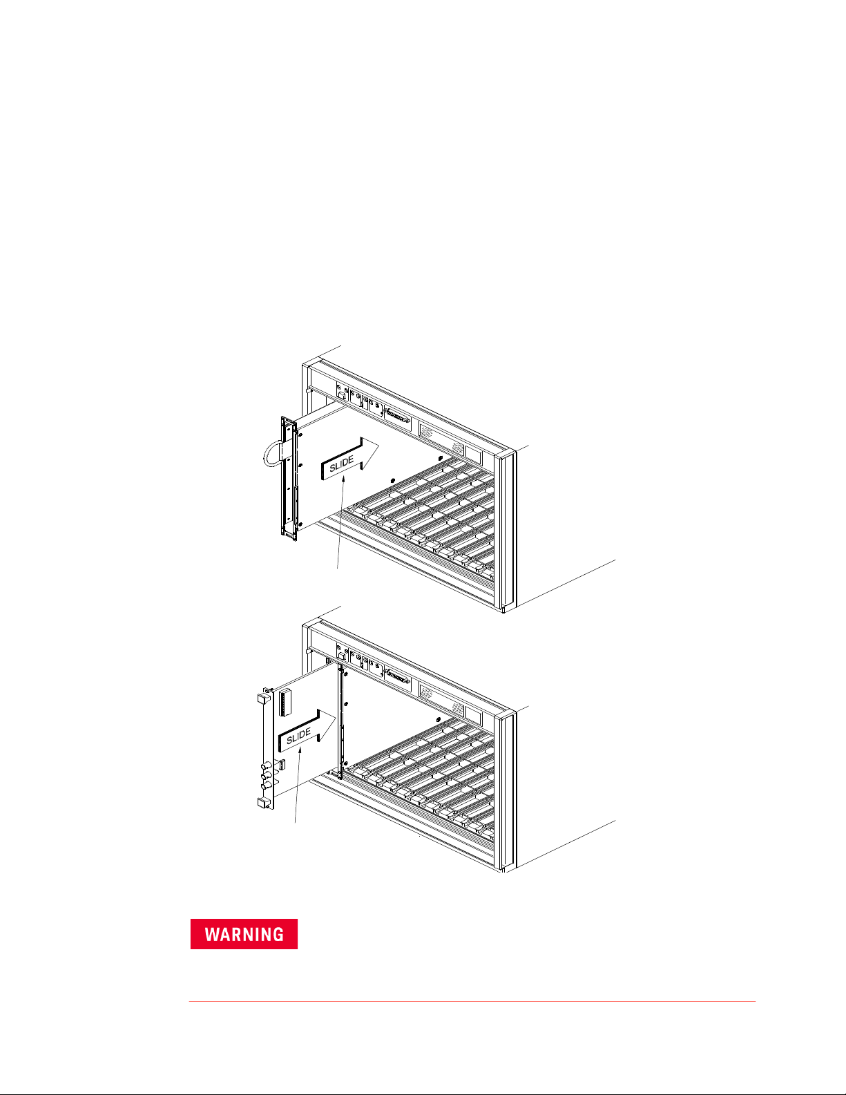
Installing VXI Instruments Getting Started
Slide the Adapter Module into
the Mainframe until it plugs into
the Backplane Connector
Connects
the Adapter Module until it
Slide the B-Size Module into
Installing A- and B-Size Instruments
Figure 3 shows the installation of A- and B-size instruments.
– Keysight E1403B A/B-size Module Carrier extends the P1 connector on the
VXIbus backplane and mounts the (A/B-size) modules flush with C-size
modules. This carrier is recommended for Keysight B-size, slave-only
devices which have the P1 connector.
– Keysight E1407A A/B Module Carrier extends the P1and P2 connectors on
the VXIbus backplane. This carrier is recommended for B-Size, slave-only
devices which have the P1/P2 connectors.
Figure 1-3 Installing A- and B-Size Instruments in the Keysight E840xA Mainframe
Keysight E8402A, E8404A C-Size Mainframes User and Service Guide 21
All instruments within the VXI mainframe are grounded
through the mainframe chassis. During installation, tighten
the instrument's retaining screws to secure the instrument
to the mainframe and to make the ground connection.
Page 22
Getting Started Configuring Your Mainframe
10
128
64
32
16
8
4
2
1
7
0
LADDR
32+64+128=2 24
CLOSED = Switch Set to 1 (ON)
OPEN = Switch Set to 0 (OFF)
RS-232
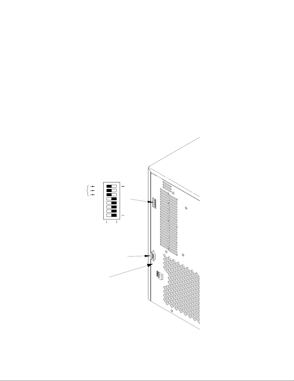
Configuring Your Mainframe
Setting the Enhanced Monitor VXI Logical Address
The Enhanced Monitor of the Keysight E8402 and E8404 mainframes plugs into
the VXI backplane from the rear of the mainframe. It does not occupy a slot in the
mainframe or tie-up the MODID line. The enhanced monitor is a message-based
device, allowing easy communication over the VXIbus (for example, through a
command module or embedded controller) or a standard RS-232 interface. The
enhanced monitor does require a VXIbus address; 224 is the factory default.
Figure 4 shows the rear panel of the Keysight E8402/E8404 VXI mainframe with
the Enhanced Monitor logical address switches and RS-232 interface.
Figure 1-4 Rear panel of the Keysight E8402 and E8404 VXI Mainframes
+5V EXT
22 Keysight E8402A, E8404A C-Size Mainframes User and Service Guide
Page 23

Configuring Your Mainframe Getting Started
RS-232 Interface
The RS-232 interface on the rear panel of the Enhanced Monitor mainframes
(Keysight E8402 and E8404) can be used to control the Enhanced Monitor from a
computer or a terminal.
Refer to Chapter 3 for RS-232 programming information. The
SYSTem:COMMunicate:SERial ... commands set and/or modify the configuration
of the Enhanced Monitor's serial interface. Serial communication commands
take effect after the end of the program message containing the command(s).
Default RS-232 parameters are:
– Baud: 9600
– Bits: 8
– Parity: None
– Stop bits: 1
– DTR/RTS: On
– Pace: XON
– Echo: On
– ERES: On
– Line buffer: On
External +5V Supply
The External +5V supply is for powering the Enhanced Monitor (including the
RS-232 interface) while the mainframe is powered down (standby mode). This
requires a stable 5 volt supply capable of 1.5A amps maximum (500mA typical,
refer to specifications in Appendix A). Refer to Figure 4.
If you use the Enhanced Monitor RS-232 interface (located on the
back of the mainframe) while the mainframe is in the standby
mode, you must supply an external +5Vdc to the +5VEXT
connector (located near the RS-232 interface). If you use the
RS-232 interface while the mainframe is powered on, you do not
need to provide the external +5Vdc.
Keysight E8402A, E8404A C-Size Mainframes User and Service Guide 23
Page 24
Getting Started Configuring Your Mainframe
13
25 18
5
14
1
Power
Supply
Front
Panel
Switch
BACKPLANE
5
18
SUB D
CONNECTOR
HP E840X
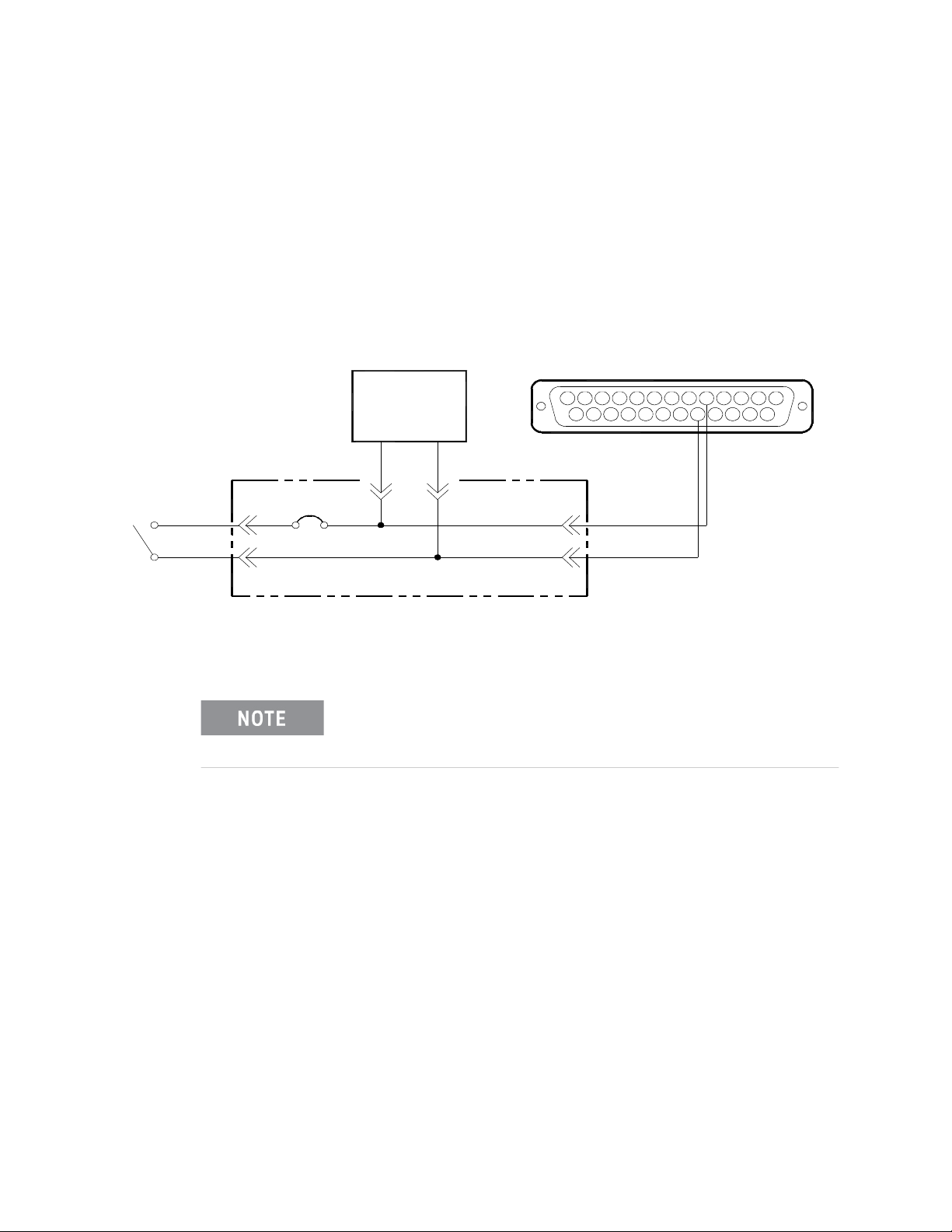
Using the Remote Power-On Pins
The remote power-on pins (pins 5 and 18) of the Diagnostic Connector allow you
to turn the mainframe on and off without using the front panel On/Stdby switch.
With the On/Stdby switch in the Stdby (off) position, connecting pin 5 to pin 18
on the diagnostic connector turns the mainframe on. Disconnecting pin 5 from
pin 18 turns the mainframe off.
Figure 1-5 Remote Standby Switch Wiring.
Pin 18 is ground in the Keysight E8402 and E8404 mainframes.
Therefore, you only need to ground pin 5 to turn the mainframe
on.
24 Keysight E8402A, E8404A C-Size Mainframes User and Service Guide
Page 25
Configuring Your Mainframe Getting Started
Location of
Resistor
Unplug
Unplug
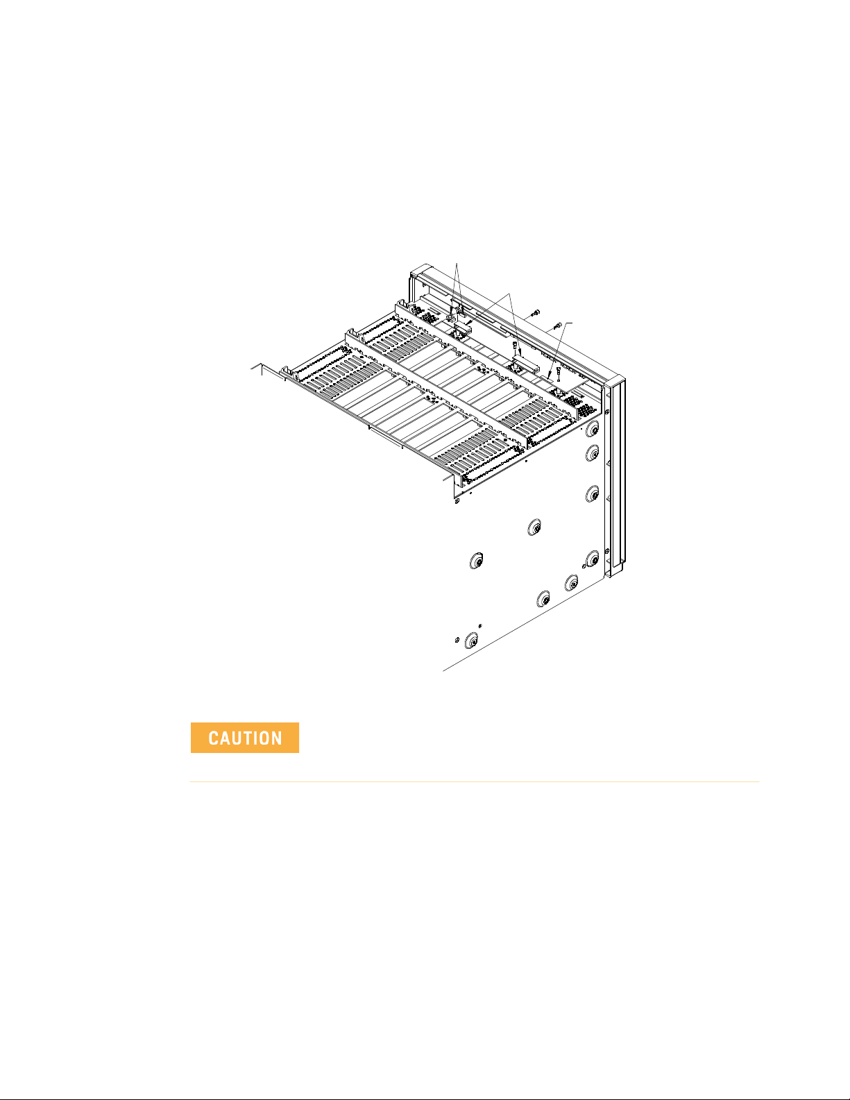
Disabling the On/Stdby Switch
The front panel On/Stdby switch is disabled by removing surface mount 0
resistor located on the front monitor board (see Figure 6). The resistor is labeled:
REM PWR JUMPER.
Figure 1-6 Disabling the On/Stdby Switch
After removing the 0 resistor, heat damage may prevent the
resistor from being re-installed to re-enable the On/Stdby
switch.
To access the Monitor Display Board and resistor:
1 Turn off the mainframe and remove the power cord.
2 Remove the mainframe cover by removing the 10 m3x6 flat head torx screws.
3 Remove the 0resistor by heating both sides simultaneously with soldering
irons. Separate the resistor from the board by gently pressing the tips of the
soldering irons together.
4 Save the resistor in order to re-enable the On/Stdby switch. Again, heat
damage may prevent the resistor from being re-installed.
Keysight E8402A, E8404A C-Size Mainframes User and Service Guide 25
Page 26

Getting Started Mainframe Options and Accessories
Mainframe Options and Accessories
Table 0-1. Keysight E840xA VXI Mainframes options and accessories
Description Option Number Product Number
Cable Tray Kit Option 914 Keysight
E8400-80914
Tinted Acrylic Door Kit Option 915 Keysight
E8400-80915
Backplane Connector Shields Option 918 Keysight
E8400-80918
Intermodule Chassis Shield Kit N/A Keysight
E8400-80919
Standard Rack Mount Adapter Kit Option 923 Keysight
E8400-80923
Flush Rack Mount Kit Option 924 Keysight
E8400-80924
VXIplug&play (VPP-8) Compatible Rack Mount Kit Option 925 Keysight
E8400-80925
Air Filter Accessory Kit Option 938 Keysight
E8400-80938
Support Rail for Standard Rack Mount Adapter or Flush Rack Mount Kit N/A Keysight E3664A
Support Rail for VXIplug&play (VPP-8) Compatible Rack Mount Kit N/A Keysight E3663A
Rack Slide Kit for Standard Adapter Kit or VXIplug&play (VPP-8) Compatible
Rack Mount Kit
N/A Keysight
1494-0411
26 Keysight E8402A, E8404A C-Size Mainframes User and Service Guide
Page 27

Keysight E8402A, E8404A C-Size Mainframes
User and Service Guide
2 Using the Enhanced Monitor
The Enhanced Monitor on the front panels of the Keysight 840xA mainframes
allow you to monitor power supply voltages, mainframe temperatures, fan
operation, and backplane activity. Figure 1 shows the mainframe front panel.
The enhanced monitor provides features such as:
– Monitoring the mainframe operating status including: blower status, slot
temperatures, and power supply voltages, current, and power. The
Enhanced Monitor generates a warning if any of these parameters exceed
limits. Refer to Chapter 3 for programming details.
– User-definable temperature limits for individual slots; if the limit is
exceeded, a beeper sounds, LEDs flash, and the display shows the warning
condition.
– Storing a history of power supply voltages, currents, and power; slot
temperatures; fan speeds; events such as mainframe power cycled on/off,
etc.
In addition, you can:
– Perform internal Enhanced Monitor Self Tests. These verify its fans and its
ability to measure the slot temperatures and power supply voltages and
currents, etc.
– Set and query Enhanced Monitor system parameters. The Enhanced
Monitor functions are programmable through either the system
commander (command module or embedded controller) or via an RS-232
port on the back of the mainframe.
– Write user text messages to the front panel display. This is useful for
communicating with an operator.
27
Page 28

Using the Enhanced Monitor
Section Indicator / Switch Description
Power On Indicator
Green - the mainframe is turned on.
Standby Indicator
System Power Supply
Indicator
Temp Indicator
Fans Fan Switch
Fans Indicator
Backplane Activity Indicator
Amber - the mainframe is in standby mode; no power is applied to VXI modules.
Both Indicators Off - there is no power applied to the mainframe.
Green - all voltages, currents, and power supply temperatures are within expected operating
ranges.
Flashing Amber - one or more power supply measurements are out of limit.
Green - all the individual slot temperatures and ambient temperatures are within normal
operating ranges.
Flashing Amber - one or more slot temperatures or the ambient temperature has exceeded
specified limits.
Full - the power supply and mainframe cooling fans are operating at full speed.
Var(iable) - the power supply and mainframe cooling fans are providing user-specified
cooling level. Fan speed is a function of the power supply temperature, ambient temperature,
and individual slot temperatures. Fan speeds operate at the lowest possible speed to
maintain user-specified cooling level.
Green - the power supply and mainframe cooling fans are operating within expected ranges.
Flashing Amber - the power supply fan or the mainframe cooling fan is not operating within
expected ranges.
Green - there is communication between instruments across the backplane. Off - there is no
communication between instruments on the backplane.
SYSFAIL Indicator
Reset Switch
Diagnostic
Connector
Display and
Keypad
Amber - one or more instruments has asserted its SYSFAIL line due to a power-on
initialization failure, self-test failure, or hardware failure. SYSFAIL is asserted momentarily at
power on and during a system reset.
Pressing the reset button asserts the SYSRESET* line on the VXI backplane. When low, this
line resets the VXI system; all VXI instruments are rest to their power-on state.
Refer to “Diagnostic Connector” on page 43.
Refer to “Using the Enhanced Monitor” on page 29
Figure 2-1 Keysight E8402A and E8404A Enhanced Monitoring Front Panel
28 Keysight E8402A, E8404A C-Size Mainframes User and Service Guide
Page 29

Using the Enhanced Monitor Using the Enhanced Monitor
Using the Enhanced Monitor
The Enhanced Monitor is a separate PC board that plugs into the VXI
backplane from the rear of the mainframe. In this way it does not
occupy a user slot on the front of the mainframe. The Enhanced
Monitor uses a standard-defined P1 Connector but a uniquely-defined
P2 Connector. It is a message-based, slave-only VXI interface card,
complete with its own VXI logical address. Refer to Chapter 3 of this
manual for SCPI programming information. This section provides
general information about the Enhanced Monitor.
– RS-232 Interface supports communication with a terminal or
computer for remote monitoring purposes only. Refer to
Chapter 3 for SCPI programming information.
-- All SCPI command are supported by the RS-232 interface.
-- The RS-232 interface is set-up only through SCPI
commands. Settings are stored in non-volatile memory.
Factory defaults are:
9600 Baud, 8 bits, No Parity, 1 Stop Bit, DTR/RTS On, XON
Pacing.
– Ambient Temperature Monitor (
the intake air stream path just above the mainframe impeller.
-- A user-defined limit can be set, default is 55
-- Limit is restored from non-volatile memory at power-on.
-- When the limit is exceeded, the monitor generates a warning
on the display, sets a status bit, the temperature LED flashes,
and the beeper sounds (if enabled).
– Power Supply Temperature Monitor (
located under a power supply transformer. The reading is
indicative of overall power supply loading.
-- If the temperature exceeds an expected level, the monitor
generates a warning on the display, sets a status bit, the
power supply LED flashes, and the beeper sounds (if
enabled).
– Module Exhaust (Slot) Temperature Monitor (
sensors, front, middle, and rear are located above each slot.
-- Temperatures may be queried in actual
rise above ambient (in
-- User-definable limits can be set for the entire cardcage or on
a slot-by slot basis.
±2 °C). The sensor is located in
°C.
±2 °C). The sensor is
±2 °C). Three
°C or as temperature
°C).
-- Limit may be set in actual temperature (default is +65
and as temperature rise above ambient (default is +15
-- Limits are restored from non-volatile RAM at power-on.
Keysight E8402A, E8404A C-Size Mainframes User and Service Guide 29
°C)
°C).
Page 30

Using the Enhanced Monitor Using the Enhanced Monitor
-- If a slot temperature exceeds the specified limit, the monitor
generates a warning on the display, sets a status bit, the
temperature LED flashes, and the beeper sounds (if enabled).
– Voltage Monitor measures all seven power supply voltages (+5,
±12, ±24, -5.2V, and -2V).
-- Voltages outside of fixed limits (based on VXI specifications)
causes the monitor to generate a warning on the display, set
a status bit, the Power Supply LED flashes, and the beeper
sounds (if enabled).
– Current Monitor measures the current from all seven power
supplies (+5, ±12, ±24, -5.2V, and -2V).
-- Currents exceeding user-specified limits (defaults to
mainframe specifications +10%) causes the monitor to
generate a warning on the display, set a status bit, the Power
Supply LED flashes, and the beeper sounds (if enabled).
– Power Monitor calculates the total output power of the power
supply [(V*I)].
-- Total output power exceeding user-specified limits (defaults
to mainframe power supply maximum) causes the monitor to
generate a warning on the display, set a status bit, the Power
Supply LED flashes, and the beeper sounds (if enabled).
– Backplane Activity Monitor monitors activity on the VXI
backplane.
-- The DS0 and DS1 backplane lines are monitored. Activity is
displayed through the front panel Activity LED. No warning is
associated with this activity.
-- SYSFAIL is also monitored. Assertion of SYSFAIL (by any VXI
module) is shown by the amber SYSFAIL LED on. It will not
sound the beeper or generate a warning on the display.
– Fan Monitor monitors the operation of the fans.
-- Fan speeds outside a fixed range generate a warning on the
display, sets a status bit, the FAN LED flashes, and the
beeper sounds (if enabled).
-- Fan level is returned as a percentage (%) of maximum speed.
– Fan Controller adjusts mainframe fan speed based on the power
supply, ambient, and individual slot temperatures. The fan can
be set to maximum or FULL speed by a front panel switch.
-- In the Variable mode, if the power supply temperature
exceeds
an expected level, the fan speed increases to maximum.
-- In the Variable mode, if the ambient temperature exceeds
°C, the fan speed increases to maximum.
+50
30 Keysight E8402A, E8404A C-Size Mainframes User and Service Guide
Page 31

Using the Enhanced Monitor Using the Enhanced Monitor
-- In the Variable mode, if any VXI module exhaust temperature
approaches a user-defined limit, fan speed increases.
-- Otherwise, fan speeds operate at the lowest possible speed
to maintain user-specified cooling level.
– Time Monitor records:
-- Total hours of operation
-- Time-on since power on, last test, last calibration, last
history reset.
-- Time remaining until the next maintenance. This time can be
set and queried by the user. A warning is generated when the
timer reaches 0. Note: this is disabled as shipped from
Keysight.
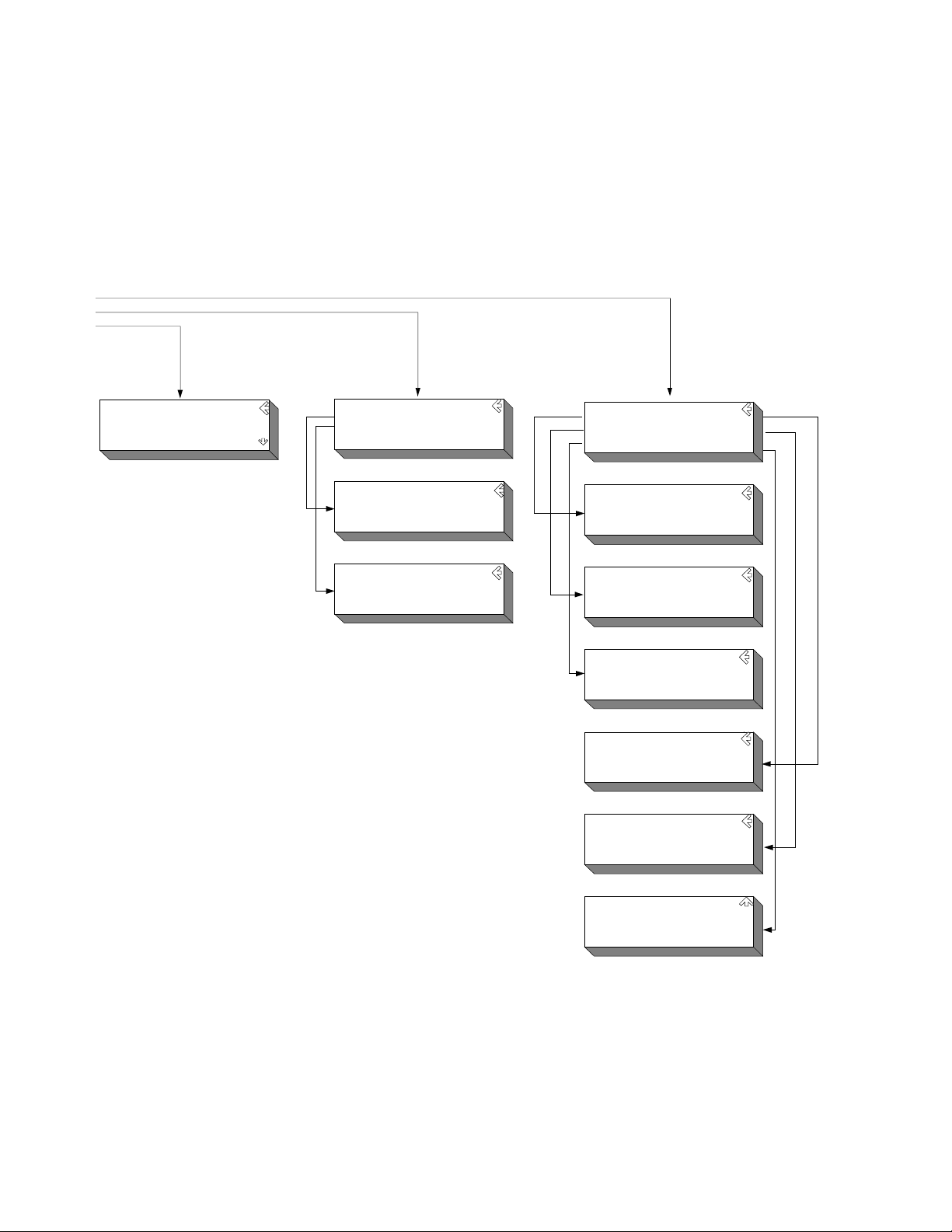
Using the Display
The Enhanced Monitor display graphically portrays status information
about the mainframe. This includes strip charts and histograms of fan
speed, slot and ambient temperature, and power supply voltage, and
power.
The first time the mainframe is powered on, the display prompts you
to select a language; either English, German (Deutsch), French
(Français), or Spanish (Español). Use the arrow keys just to the right of
the display to highlight a language then press the
Enter key. All
display and help screens will appear in the selected language.
Use the up/down arrow keys to highlight a display item, then press the
Enter key to select that item. In the upper right hand corner of all
displays (except the language selection display) is an arrow; selecting
this arrow and pressing the
display. Some displays also have a question mark (
Enter key moves you back to the previous
?) in the upper
right corner. Selecting the question mark brings up a help screen
describing the display. Figure 2 shows three typical displays and a
help screen.
Keysight E8402A, E8404A C-Size Mainframes User and Service Guide 31
Page 32
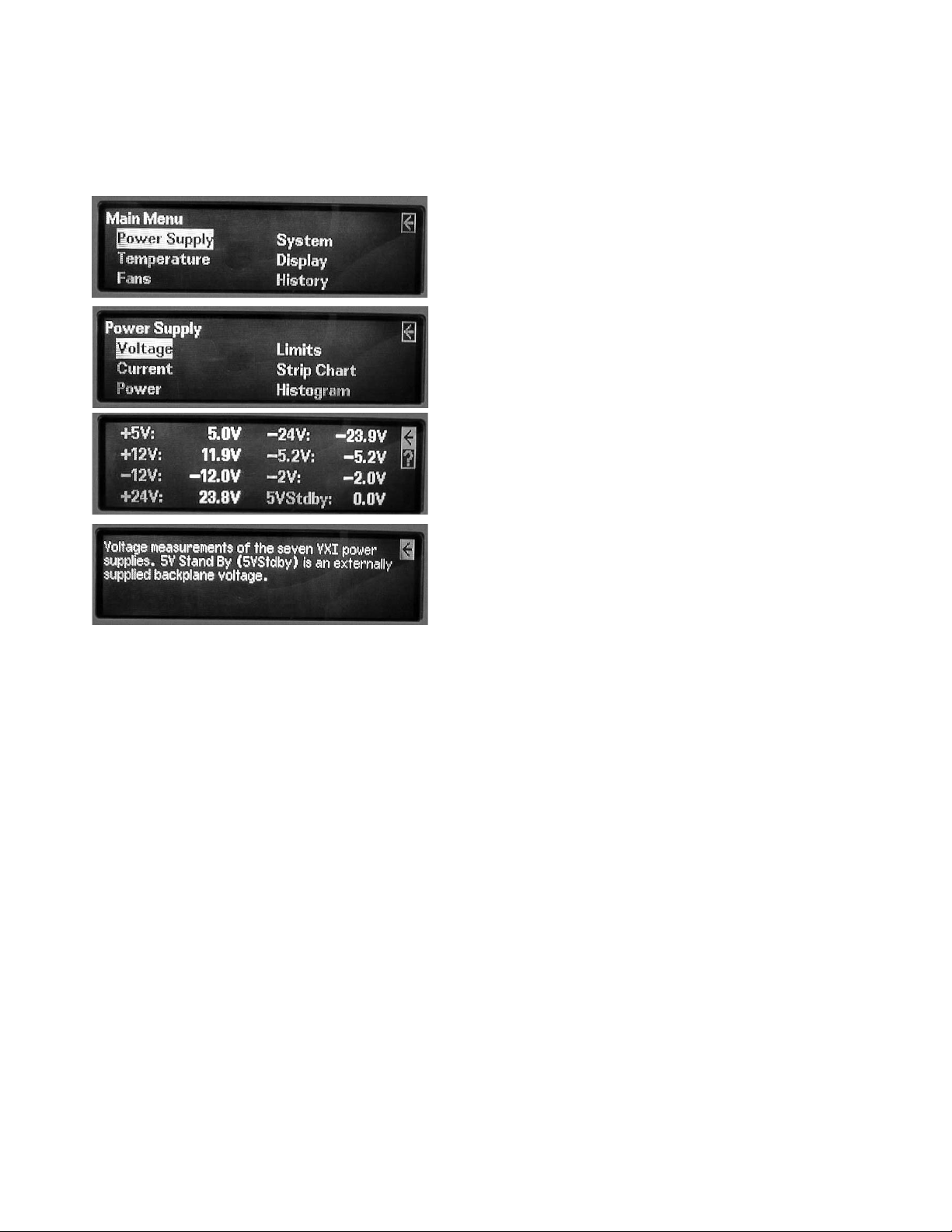
Using the Enhanced Monitor Using the Enhanced Monitor
Use the UP/DOWN arrow keys to highlight a
menu item (in this case "Power Supply" is
highlighted). Press the Enter key to select it.
Use the UP/DOWN arrow keys to highlight a
menu item (in this case "Voltage" is
highlighted). Press the Enter key to select it.
This display shows the actual measured power
supply voltages. Use the UP/DOWN arrow keys
to highlight either the arrow or the Question
Mark. Highlight the Question Mark and press the
Enter key for a display description.
Press the Enter Key to return to the
previous display.
Figure 2-2 Typical Displays for the Keysight E8402A and E8404A Enhanced Monitor
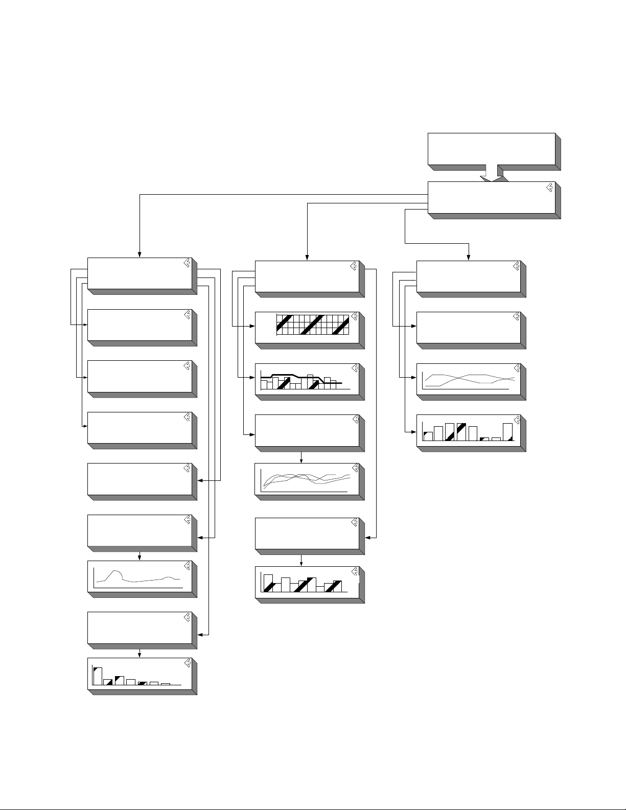
Menu Map
Figure 3 shows a complete display menu map for the Enhanced Monitor.
32 Keysight E8402A, E8404A C-Size Mainframes User and Service Guide
Page 33
Using the Enhanced Monitor Using the Enhanced Monitor
Power Supply
Volta ge L imits
Current Stripch art
Power Histogr am
+5V: 5.0V -24V: -24.0V
+12V: 12.0V -5.2V : -5.1V
-12V: - 12.0V -2V: -2. 0V
+24V: 24.0V 5VStd by: 0.0V
+5V: 10.9A -24V : -1.2A
+12V: 1.8A -5.2V: -6.2A
-12V: -0.9A -2V: - 2.3A
+24V: 1.3A
+5V: 54W -24V: 29W
+12V: 21W -5.2V: 32W
-12V: 10W -2V: 5W
+24V: 30W Total: 182W
+5V: 460W -24V: 360W
+12V: 180W -5.2V: 312W
-12V: 180W -2V: 60W
+24V: 360W Total: 1000W
Power Supply Strip Chart
+5V +24 V -2V Total
+12V -24V 5VStdby
-12V -5.2V PS Temp
Power Supply Histogram
+5V +24 V -2V Total
+12V -24V 5VStdby
-12V -5.2V PS Temp
?
?
?
?
MPSupply
PSVoltage
PSCurrent
PSPower
PSLimit
MPSStripchar
MPSHistogram
?
PSSTripchar[1..10]
?
PSHistogra[1..10]
Temperature
Status Histogram
Limits
Stri pchart
°C R
M
Amb
F
29
slot 0 1 2 3 4 5 6 7 8 9 10 11 12
Temperature Stripchart
Slot 0 Slot 3 Sl ot 6 Slot 9 Slot 12
Slot 1 Slot 4 Slot 7 Slot 10 Amb
Slot 2 Slot 5 Slot 8 Slot 11
?
?
MTEMperature
TSTa tus
TLIM its
MTSTripchart
?
THIStogram[0..13]
?
TSTRipchart[0..13]
Tempe rature Histog ram
Slot 0 Slot 3 Sl ot 6 Slot 9 Slot 12
Slot 1 Slot 4 Slot 7 Slot 10 Amb
Slot 2 Slot 5 Slot 8 Slot 11
MTHistogram
Fans
Status
Stripch art
Histogr am
Present Level of Fans: 65%
Main Fan Speed: 1498 RPM
Power Supply Fan Speed: 2214 RPM
Power Supply Fan2 Speed: 2056RP M
?
?
?
MBLower
BSTatus
BSTripchart
BIHistogram
Select a Language
English Francai s
Deuts ch
Espanol
Mainfra me Stat us
Power S upply System
Temperat ure Display
Fans History
LANGua ge
MMAin
Note:
the names under each display refer to
the parameter for the DISPlay:WINDow
command. Refer to the DISPlay:WINDow
command for additional information.
Figure 2-3 Keysight E8402 & E8404 Enhanced Monitor Display Menu Map
Keysight E8402A, E8404A C-Size Mainframes User and Service Guide 33
Page 34
Using the Enhanced Monitor Using the Enhanced Monitor
System
Log RS-232
Timer VXIBus
Beeper About
Hours since Power-On: 13
Cumulative Hours On: 16
Hours since last Cal: 16
Number of time s powere d on: 16
?
?
?
?
Maintenance Timer
Timer Interval Hours: Disabled
Hours Remaining: Disabled
Beeper State
Use Up/Down keys to change state
Beeper = On
Baud: 9600 Parity: None
Bits: 8 Pace: XON
Stop Bits: 1 Echo: On
RTS: Off
?
?
MSYStem
SLOG
STIMer
SBEeper
SRS232
VXI Message Based Servant
Interrupt Line: 1
Logical Address: 224
HP E8404A Revision A.01.0 0
1000W AC Supply
Serial Number: 0
Name: not set
?
?
Event Hour
Mainframe Powered Off 413
Temperature Alarm, Slot 3 250
Fan Alarm, Impeller 250
HQUEue
Display
Screen Saver
Contrast
Screen Saver
Turns Display off after 10 minutes
Use Up/Down keys to change state.
Screen Saver = Off
Displ ay Cont rast
Use t he Up/Down keys to adj ust
contrast, then press Enter.
MDISplay
DSSaver
DCONtrast
SVXI
SABout
Figure 2-4 Keysight E8402 & E8404 Enhanced Monitor Display Menu Map (continued)
34 Keysight E8402A, E8404A C-Size Mainframes User and Service Guide
Page 35

Enhanced Monitor Fan Control Using the Enhanced Monitor
Enhanced Monitor Fan Control
With the front panel fan switch in the VAR position, the Enhanced
monitor controls the fan speed based on slot temperature limits you
specify. With the fan switch in the FULL position, the fan operates at
full speed.
Essentially, the Enhanced Monitor’s fan control has two contrasting
functions: 1) keep the VXI modules installed in the cardcage cool and
2) operate as quietly as possible. These are somewhat conflicting
goals because to operate at its quietest, the fan would have to be off
and hence not keep the modules cool. Alternately, at its coolest, the
fans would have to be full on and the airflow is not quiet. Therefore,
the fan control algorithm is to keep the mainframe as quiet as possible
while cooling the VXI modules adequately.
What is adequate cooling? You specify it through your selection of slot
temperatures. For example, if you specify slot 7 temperature to be
maintained within 15 °C of the ambient temperature, the fan controller
adjusts fan speed until the cooling air coming off slot 7 is just under
15 °C above ambient. And it will keep it there, adjusting the fan speed
as needed to maintain that temperature rise no matter what the
ambient temperature might do. That way, the fan noise is at its lowest
while maintaining appropriate cooling.
Each slot is monitored and compared to the specified slot temperature
limits every two seconds. The slot closest to its limit is allowed to
approach the limit in order to keep the fan speed as low as possible.
If you want a cooler mainframe, lower the slot temperature limits. If
you want a quieter mainframe, raise the temperature limits. Just
remember that the Enhanced Monitor Fan Controller is very accurate;
if you specified
30 °C rise above ambient, the controller will maintain a limit just below
30 °C.
There is one exception. The power supply cooling overrides all other
cooling requirements. For example, you may specify a 30 °C limit for
all slots, but as you monitor the slot temperatures you notice that no
slot is approaching the limit. It is likely that the Enhanced Monitor is
working to keep the power supply adequately cooled. Power supply
cooling requirements are primarily driven by the load placed on the
power supply. It needs more cooling if it is significantly loaded. So, if
the fan controller stops dropping the fan speed even though the slot
temperatures are not close to the specified limits, it is probably
because the power supply cooling requirements are dominating.
Software Control of Fan Speed
The SYSTem:BLOWer:STATe command can change the state of the
fans from VARiable to FULL at any time. When software control has
set the fans to FULL, the front panel fan switch can be set to variable
Keysight E8402A, E8404A C-Size Mainframes User and Service Guide 35
Page 36

Using the Enhanced Monitor Enhanced Monitor Fan Control
and the fans will remain at FULL. Software control can not put a mainframe with
its switch set to FULL into a variable fan state. FULL means that the fans will run
at full speed no matter what the conditions in the mainframe. VARiable means
that the enhanced monitor sets the fan speed based on the temperature
conditions in the mainframe and the temperature limits set by the user.
36 Keysight E8402A, E8404A C-Size Mainframes User and Service Guide
Page 37

Setting Enhanced Monitor Limits Using the Enhanced Monitor
Setting Enhanced Monitor Limits
The Keysight E840x Enhanced Monitor has several limits that affect when it will
issue warnings. Each limit should be selected based on the VXI modules installed
in the mainframe.
Temperature Limits
The Enhanced Monitor monitors two types of temperature limits. First are the
"Delta slot temperature limits" whose primary function is to pass your specified
temperature limits to the Fan Controller (refer to “Enhanced Monitor Fan Control”
on page 35). If these limits are not maintained, a warning is issued. The default
value is 15 °C rise above ambient; this is a compromise between cooling and
noise. Check the specifications of your installed VXI modules to determine
sensitivity to temperature variation. You may need to specify a smaller delta slot
temperature for some modules.
Second are the absolute temperature limits, for both individual slots and the
ambient temperature. These guard the top end of the acceptable temperature
spectrum and generate warnings if exceeded. The default values are generally
acceptable to most VXI modules; but you should verify the temperature ratings
for all VXI modules installed in the mainframe and set the slot’s absolute
temperature limit accordingly. For example, many modules are specified for a
temperature range of 0 to 55 °C and assume a
10 °C rise to occur in operation. Therefore, their absolute temperature is safely 65
°C (the default). But, if a VXI module is only rated to 45 °C (and assumes a 10 °C
rise) then its slot should have an absolute temperature limit of 55 °C. You might
set the limit lower for earlier warning.
Use the
limits, both ambient and delta slot temperatures. Use the
STATus:QUESTionable:TEMPerature:LEVEL? to determine the actual threshold
when an over-temperature warning will sound.
STATus:QUEStionable:TEMPerature:LIMit? command to set temperature
Current and Power Limits
By default, the Enhanced Monitor provides power supply current and power limit
warnings only when the power supply is exceeding its capacity. But it is unlikely
that all seven supplies will be used at maximum capacity. Consequently, this
warning is generally too late for most applications. For example, the +5V supply
in the Keysight E8404 is capable of providing up to 90A (peak current, refer to
Appendix A). It is therefore capable of delivering the regulated voltage into nearly
a dead short -- 0.06. For this reason, you should specify current and power
limits to reflect the actual needs of the VXI modules installed in the mainframe.
Then a warning is generated in sufficient time to correct a problem.
Keysight E8402A, E8404A C-Size Mainframes User and Service Guide 37
Page 38

Using the Enhanced Monitor Setting Enhanced Monitor Limits
To set current limits, calculate the worst case current needed on each supply for
your application, add 10%, and set your current limit to this value. Alternately,
allow your system to operate normally for a time, query the maximum values
measured by the Enhanced Monitor’s history subsystem, and set the current limit
to a comfortable margin above this maximum. Do this for each of the seven VXI
supplies and for the total power value. In this way, the Enhanced Monitor can
issue a warning when a module begins using more power than normal. Use the
STATus:QUEStionable:CURRent:LIMit command (page 131) to set current limits,
and STAT:QUES:POW:LIM to set the total power limit.
Handling Warnings
With the limits set, the mainframe will beep if a limit is exceeded. However, you
need to include exception procedures in your computer program so that the
program can handle the warnings. To do this, you need to enable the Enhanced
Monitor’s Status Subsystem to interrupt the computer when a warning occurs.
Refer to Chapter 3, “Example 2: Setting up the Mainframe” on page 51, for a
program example demonstrating this procedure.
Save The Limits
Once you have specified temperature and voltage/power limits for your
mainframe, remember to save the limits in non-volatile memory. Otherwise, you
will start again after a mainframe power-down or reset. Use the
command to save the values in non-volatile memory.
SYSTem:NVSave
38 Keysight E8402A, E8404A C-Size Mainframes User and Service Guide
Page 39

Enhanced Monitor Measurement Cycles Using the Enhanced Monitor
Enhanced Monitor Measurement Cycles
The Keysight E8402 and E8404 Enhanced Monitor monitors over 80 signals
throughout the mainframe every two seconds. These measurements are fed to
the display, the Status Subsystem (for warnings), the History Subsystem (for
storage), and the Fan Controller. The display shows the measurements pertinent
to the screen displayed, updated every two seconds. The Status Subsystem sets
status bits in the condition registers, updated every two seconds. The History
Subsystem calculates minimums, maximums, and histogram values, updated
every two seconds. However, the Enhanced Monitor stores its measurements in
the Trace Subsystem only once every 10 seconds.
During the measurement cycle, the Measuring bit in the Operational Status
Condition Register is set and then cleared. This allows you to synchronize with
the measuring cycle if you want to.
Keysight E8402A, E8404A C-Size Mainframes User and Service Guide 39
Page 40
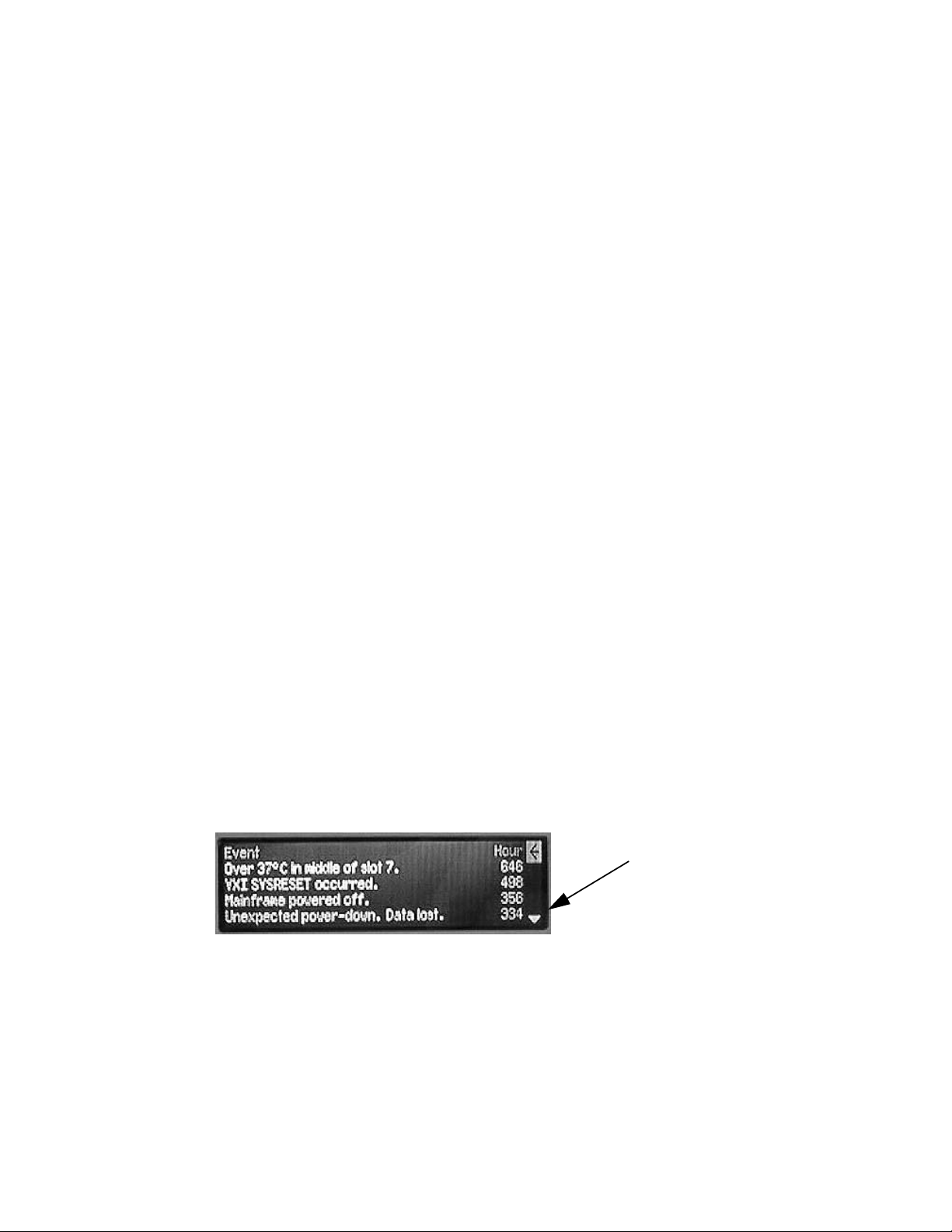
Using the Enhanced Monitor Using the History Queue
Using the History Queue
The Keysight E840x Enhanced Monitor provides many history feature records
such as: minimum and maximum values, histograms, operating times, and event
logs. As you begin to use the mainframe, the history features won’t be of much
use -- very little has happened, there is no history to record. But as time passes,
the history features can provide valuable insights into the trends of your test
system. Then, when you encounter a problem in your tests system, you have a
record of events to evaluate:
– What type of environment has the module experienced?
– What events led up to the failure?
– What changes from one test system to another?
Over time, familiarity with the problems of one particular test system may lead to
predictive knowledge about the system. Then, by watching those predictive
events using the history feature, you can prevent problems.
HISTory Queue
One of the history features is history queue – a list of events that occurred in the
mainframe. History events are recorded with the operating time that the event
took place (the operating time is the number of seconds since the mainframe
was manufactured). The history queue is available through the display; operating
time is displayed in hours. Operating Events are shown with the most recent
displayed first, earliest events displayed last. Figure 5 shows an example history
display.
To access the history queue, select
execute the command:
up and down the list (Up/Down arrows appear in the display only when
additional data is available) four events at a time.
Figure 2-5 Example History Queue Display
History from the Mainframe Status display or
DISP:WIND HQU. Use the Up/Down arrow keys to page
Down arrow indicates
more data is available.
Use Up/Down keys to
scroll through display.
40 Keysight E8402A, E8404A C-Size Mainframes User and Service Guide
Page 41

RS-232 Programming Using the Enhanced Monitor
RS-232 Programming
The RS-232 port on the Enhanced Monitor is primarily a debug port, designed for
use with a dumb terminal or terminal emulator program on a PC. This allows you
to execute SCPI commands directly without an application program and to
monitor any errors in the error queue (including those generated through the VXI
interface programming). It also allows you to query the Enhanced Monitor while
the mainframe is in standby if an external +5VDC is applied to the 5V EXT
terminals. The RS-232 port is the only possible source for temperature
calibration since the mainframe must be empty for temperature calibration.
®
Windows 95
Terminal or HyperTeminal. These applets provide a convenient method of using
the Enhanced Monitor. Use an appropriate nine-pin female to nine-pin female
RS-232 cable (such as the Keysight 24542U) for connection between the PC and
the Enhanced Monitor. Configure the Terminal settings for generic TTY, and the
communication settings to match those of the Enhanced Monitor.
Default RS-232 parameters are:
and Windows NT® provide a terminal emulator program called
– Baud: 9600
– Bits: 8
– Parity: None
– Stop bits: 1
– DTR/RTS: On
– Pace: XON
– Echo: On
– ERES: On
– Line buffer: On
Refer to Chapter 3 for RS-232 programming information. The
SYSTem:COMMunicate:SERial ... commands set and/or modify the configuration
of the Enhanced Monitor's serial interface. Serial communication commands
take effect after the end of the program message containing the command(s).
If you use the Enhanced Monitor RS-232 port (located on the back
of the mainframe) while the mainframe is in the standby mode,
you must supply an external +5Vdc to the +5VEXT connector
(located near the RS-232 port). If you use the RS-232 port while
the mainframe is powered on, you do not need to provide the
external +5Vdc.
Keysight E8402A, E8404A C-Size Mainframes User and Service Guide 41
Page 42

Using the Enhanced Monitor RS-232 Programming
The Enhanced Monitor also provides several short cuts, primarily for terminal
use:
Backspace In TERMinal mode, a backspace means "back-up." It becomes a
space in RAW mode.
Ctrl-R In TERMinal mode, this provides a "recall last command string" feature.
It is ignored in RAW mode
Ctrl-T In either TERMinal or RAW mode, Ctrl-T performs a
SYSTem:COMMunication:PRESet:TERMinal command. This puts the
Enhanced Monitor into its terminal mode at whatever baud rate
presently set.
Ctrl-C In either TERMinal or RAW mode, Ctrl-C performs the equivalent of a
Device Clear. It can interrupt a command that is taking too long to
execute and makes it possible to reset the Enhanced Monitor (*RST).
Be sure to turn off the Terminal applet’s use of the control keys for Windows use
if you want to use these short cuts.
The RS-232 port can be used to program the Enhanced Monitor. Be careful when
programming this way though. Remember that you have to turn off terminal
features like echo and immediate error. Do not try to use both the VXI
programming interface and the RS-232 port at the same time. They both access
the same error queue and status registers.
You should avoid changing RS-232 port parameters through the RS-232 port. It
will work but you must be careful otherwise you may lose communications.
Intersperse your commands with queries. This will help you stay synchronized
with the port. If you reattach a terminal after using a computer and see no
character echo, Ctrl-T should return the port to terminal mode.
42 Keysight E8402A, E8404A C-Size Mainframes User and Service Guide
Page 43

Diagnostic Connector Using the Enhanced Monitor
Diagnostic Connector
The 25-pin Sub-D diagnostic connector provides access to backplane voltages,
power supply and backplane temperatures, and output signals. The pins are
described in Table 2-1.
Table 2-1 Diagnostic Connector Pin Descriptions
Pin # Function Description
1 +5 VM +5V backplane voltage monitor (high impedance). (+4.875 Vdc to +5.125 Vdc)
2 -12 VM -12V backplane voltage monitor (high impedance). (-12.6 Vdc to -11.64 Vdc)
3 -24 VM -24V backplane voltage monitor (high impedance). (-25.2 Vdc to -23.28 Vdc)
4 -2 VM -2V backplane voltage monitor (high impedance). (-2.1 Vdc to -1.9 Vdc)
5 Rem On Remote power on. See “Using the Remote Power-on Pins.”
6 +5 VC +5 VDC source output (1A maximum).
7 +12 VC +12 VDC source output (1A maximum).
8 +5 V Stdby Input for +5V STDBY (1A maximum for pins 8 and 21 combined).
9 GND Chassis ground.
10 SysReset * TTL low-true input signal causes system reset, output indicates system reset.
NOTE: If you use this pin you must not violate VXI specifications.
11 PS Temp Output voltage proportional to power supply temperature (0 VDC at 0 °C, with a rise of
10 mV per degree centigrade).
12 Ref Temp Output voltage proportional to backplane temperature (0 VDC at 0 °C, with a rise of 10 mV per
degree centigrade). A function of the ambient temperature and load.
At no load, T
T
~ 14 °C + ambient. At full load and low fan speed, T
ref
13 Fans OK * TTL low-true output voltage indicates power supply and backplane cooling fans are operating.
14 +12 VM +12V backplane voltage monitor (high impedance). (+11.64 Vdc to +12.6 Vdc)
15 +24 VM +24V backplane voltage monitor (high impedance). (+23.28 Vdc to +25.2 Vdc)
16 -5.2 VM -5.2V backplane voltage monitor (high impedance). (-5.46 Vdc to -5.044 Vdc)
17 GND Chassis ground.
18 REM Rtn Remote power switch return. See “Using the Remote Power-On Pins.”.
19 V OK * TTL low-true output voltage indicating the +5V, ± 12V, ± 24V, -5.2V, and -2V power supply
voltages are within ± 8% of its allowed variation.
20 GND Chassis ground.
21 +5 V Stdby Input for +5V STDBY (1A maximum for pins 8 and 21 combined).
22 GND Chassis ground.
23 ACFAIL* TTL low-true output asserted by the mainframe power monitor at power down or whenever a
loss of power is detected.
24 GND Chassis ground.
25 RSV
Reserved. Used for Timer Verification; refer to Chapter 4.
~ 2 °C + ambient. At full load and high fan speed,
ref
ref
~ 20 °C + ambient.
Keysight E8402A, E8404A C-Size Mainframes User and Service Guide 43
Page 44

Using the Enhanced Monitor Diagnostic Connector
+5VC (pin 6)
The +5 volt output allows you to power external TTL circuits if required. The
maximum current allowed from this supply is 1.0A
+12VC (pin 7)
The +12 volt output allows you to power external circuits, charge a battery, or
power relays if required. The maximum current allowed from this supply is 1.0A
+5V STDBY (pins 8, 21)
This provides an input to the mainframe backplane for a +5V DC standby power
source. This may be from a separate battery or power supply. The maximum
current allowed is 1A total (pins 8 and 21 wired in parallel). It can be used to
power timers and other circuits when the mainframe is in standby mode.
SYSRESET* (pin 10)
This pin provides an extension of the VXI backplane SYSRESET* signal line. It can
be used to monitor for SYSRESET* or to send a SYSRESET* tot he backplane.
Shorting this line to ground asserts the SYSRESET* signal to the system. If you
use an extension cable from the Diagnostic Connector, make certain that you do
not violate the VXI backplane electrical specifications (i.e. keep the cable as
short as possible, buffer the signal line, etc.).
ACFAIL* (pin 23)
This pin lets you monitor the ACFAIL* signal from the VXI backplane. If you use an
extension cable from the Diagnostic Connector, make certain that you do not
violate the VXI backplane electrical specifications (i.e. keep the cable as short as
possible, buffer the signal line, etc.).
44 Keysight E8402A, E8404A C-Size Mainframes User and Service Guide
Page 45

Keysight E8402A, E8404A C-Size Mainframes
User and Service Guide
3 Programming the Enhanced
Monitor
This chapter explains how to program the enhanced monitor of the Keysight
E8402A and E8404A VXI mainframes including:
– Complete C language program examples
– Complete SCPI Command Reference
– Complete IEEE 488.2 Common Command Reference
Understanding SCPI Commands
Commands are separated into two types: IEEE 488.2 Common Commands and
SCPI Commands.
Common Command Format
The IEEE 488.2 standard defines the Common commands that perform functions
like reset, self-test, status byte query, etc. Common commands are four or five
characters in length, always begin with the asterisk character (*), and may
include one or more parameters. The command keyword is separated from the
first parameter by a space character. Some examples of Common commands are
shown below:
*RST *ESR 32 *STB? *TST?
SCPI Command Format
The SCPI commands perform functions like setting parameters, making
measurements, and querying instrument states or retrieving data. A subsystem
command structure is a hierarchical structure that usually consists of a top level
(or root) command, one or more lower-level commands, and their parameters.
The following example shows part of a typical subsystem:
:DISPlay
[:WINDow] <display window>
[:WINDow]?
:TEXT
[:DATA] <string>
[:DATA]?
:DISPlay is the root command, [:WINDow] is a second-level command with
parameter.
45
Page 46

Programming the Enhanced Monitor Understanding SCPI Commands
Command Separator
A colon (:) always separates one command from the next lower-level command
as shown in the example subsystem above.
Abbreviated Commands
The command syntax shows most commands as a mixture of upper- and
lowercase letters. The uppercase letters indicate the abbreviated spelling for the
command. For shorter program lines, send the abbreviated form. For better
program readability, you may send the entire command. The instrument will
accept either the abbreviated form or the entire command.
For example, if the command syntax shows DISPlay, then DISP and DISPLAY are
both acceptable forms. Other forms of DISPlay, such as DISPL or DISPLY will
generate an error. You may use upper- or lowercase letters. Therefore, DISPLAY,
display, and DiSpLaY are all acceptable.
Implied Commands
Implied commands are those which appear in square brackets ([ ]) in the
command syntax. (Note that the brackets are not part of the command and are
not sent to the instrument.) Suppose you send a second-level command but do
not send the preceding implied command. In this case, the instrument assumes
you intend to use the implied command and it responds as if you had sent it.
Examine the example subsystem above. The second level command [:WINDow]
is an implied command (indicated by square brackets []). You can use either
form:
:DISPlay:WINDow <display window> or :DISPlay <display window>
46 Keysight E8402A, E8404A C-Size Mainframes User and Service Guide
Page 47

Understanding SCPI Commands Programming the Enhanced Monitor
Parameters
Parameter Types. The following table contains explanations and examples of
parameter types you might see later in this chapter.
Parameter Type Explanations and Examples
Enumerated
(abbreviated enum in
the Parameter tables)
Numeric Accepts all commonly used decimal representations of numbers including
int16 or uint32 int16 means a signed 16-bit integer value;
float floating point number
Boolean Represents a single binary condition that is either true or false.
Accepts a specified set of words as the parameter.
For example, the <display window> parameter of the :DISPlay:WINDow
command accepts: MMAin, MPSupply, MTEMperature, MBLower, MDISplay,
MSYStem . . .
optional signs, decimal points, and scientific notation.
123, 123E2, -123, -1.23E2, .123, 1.23E-2, 1.23000E-01.
Special cases include MIN, MAX, and DEF.
uint32 means an unsigned 32-bit integer value.
ON, OFF, 1, 0.
Optional Parameter: Parameters shown within square brackets ([ ]) are optional
parameters. (Note that the brackets are not part of the command and are not
sent to the instrument.) If you do not specify a value for an optional parameter,
the instrument chooses a default value.
Parameters separated by a vertical bar (|) indicate the only possible choices. For
example:
SYSTem:COMMunicate:SERial:CONTrol:RTS ON|OFF
the ON|OFF means that you can set RTS to either ON or OFF.
Linking Commands
Linking IEEE 488.2 Common Commands with SCPI Commands. Use a semicolon
(;) between the commands. For example:
*RST;SYSTem:VERSion? or SYSTem:VERSion?;*RST
Linking Multiple SCPI Commands. Use both a semicolon (;)and a colon (:)
between the commands. For example:
SYST:COMM:SER:BAUD 19200;:SYST:COMM:SER:BITS 8
Keysight E8402A, E8404A C-Size Mainframes User and Service Guide 47
Page 48

Programming the Enhanced Monitor Programming Examples
Programming Examples
This section contains SCPI program examples that demonstrate how to read
history data from the enhanced monitor, perform the self test, set and verify limit
warnings. The program examples are written in ANSI C language with Keysight
VISA extensions. To run one of these programs you must have the Keysight SICL
Library, the Keysight VISA library, an Keysight-IB interface module installed in an
external PC, an Keysight E1406 Command Module, and the enhanced monitor in
either the Keysight E8402A or E8404A VXI mainframe.
The following program examples are developed with the ANSI C language using
the Keysight VISA extensions. The program was written and tested in Microsoft
Visual C++
A more complete Enhanced Monitor setup example is provided on the Keysight
Universal Instrument Drivers CD ROM in the directories:
®
but can be compiled under any standard ANSI C compiler.
\examples\Keysighte8402
\examples\Keysighte8404
48 Keysight E8402A, E8404A C-Size Mainframes User and Service Guide
Page 49

Programming Examples Programming the Enhanced Monitor
Example 1: Self Test & Verification
The following example program resets the Enhanced Monitor, performs a
complete self test (this can take up to seven minutes to complete), read the
mainframe model number string, read the mainframe serial number, and writes
data to the Enhanced Monitor display.
#include <visa.h>
#include <stdio.h>
#include <stdlib.h>
/* Interface address is 9, Enhanced Monitor secondary address is 224*/
/* #define INSTR_ADDR “GPIB0::9::224::INSTR” */
#define INSTR_ADDR “GPIB-VXI0::224::INSTR”
/* a simple VISA error-handling macro. This version prints the line number
from which
it was called and exits if it gets an error */
#define CHECKERR(errStatus, line) if (errStatus < VI_SUCCESS) { \
printf(“Line %d: error %x returned from visa. Aborting\n”, \
line, errStatus); \
exit (errStatus); \
}
int main()
{
ViStatus errStatus;
/*Status from each VISA call */
ViSession viRM;
/*Resource mgr. session */
ViSession en_mon;
/* Enhanced Monitor session */
int into;
/* variable for *OPC? */
char id_string[256];
/* Model Number string */
char ser_num[256]
/* mainframe serial number */
chr txt_string[256]
/* String sent to display */
char selftst_string[256];
/* Self-test string */
/* Open the default resource manager */
errStatus = viOpenDefaultRM (&viRM);
CHECKERR(errStatus, __LINE__);
Keysight E8402A, E8404A C-Size Mainframes User and Service Guide 49
Page 50

Programming the Enhanced Monitor Programming Examples
/* Open the Enhanced Monitor instrument session */
errStatus = viOpen(viRM,INSTR_ADDR,VI_NULL,VI_NULL,&en_mon);
CHECKERR(errStatus, __LINE__);
/* Reset the Enhanced Monitor */
errStatus = viQueryf(en_mon, “*RST;*OPC?\n”,”%i”,&into);
CHECKERR(errStatus, __LINE__);
/* Set Timeout Value to 8 minutes for Self Test */
viSetAttribute (en_monA,VI_ATTR_TMO_VALUE,480000);
/* Perform Enhanced Monitor Self-Test - approx. 7 minutes */
errStatus = viQueryf(en_mon, “TEST:ALL?\n”, “%t”, selftst_string);
CHECKERR(errStatus, __LINE__);
printf(“Self Test Result is %s\n”, selftst_string);
/* Query the mainframe model */
errStatus = viQueryf(en_mon, “SYSTEM:MODEL?\n”, “%t”, id_string);
CHECKERR(errStatus, __LINE__);
printf(“ID is %s\n”, id_string);
/* Query the mainframe serial number*/
errStatus = viQueryf(en_mon, “SYSTEM:SNUMBER?\n”, “%t”, ser_num);
CHECKERR(errStatus, __LINE__);
printf(“Serial Number is: %s\n”, ser_num);
/* Write a Message to the Enhanced Monitor Display */
errStatus = viPrintf(en_mon,”DISP:TEXT %s \n”,“\\n Hello World!”);
CHECKERR(errStatus, __LINE__);
/* Close the Enhanced Monitor Instrument Session */
errStatus = viClose (en_mon);
CHECKERR(errStatus, __LINE__);
/* Close the Resource Manager Session */
errStatus = viClose (viRM);
CHECKERR(errStatus, __LINE__);
return VI_SUCCESS;
}
50 Keysight E8402A, E8404A C-Size Mainframes User and Service Guide
Page 51

Programming Examples Programming the Enhanced Monitor
Example 2: Setting up the Mainframe
The following example program demonstrates how to customize the mainframe’s
Enhanced Monitor features. Specifically, it enables the status subsystem, sets
temperature limits for a specific slot in the mainframe and verifies the limit. To
simulate a limit warning, you can set the limit to a value lower than ambient
temperature.
#include <visa.h>
#include <stdio.h>
#include <stdlib.h>
/* Interface address is 9, Enhanced Monitor default secondary address is 224
*/
/* #define INSTR_ADDR “GPIB0::9::224::INSTR” */
#define INSTR_ADDR “GPIB-VXI0::224::INSTR”
/* Enable STAT:OPER bits for Calibrating, Measuring, History Queue Full */
#define OPER_ENAB (ViUInt16)0x0411
/* Enable STAT:QUES bits for Voltage Summary, Current Summary, Power,
Temperature summary, Calibration, Blower summary, UMCounter, Unexpected
parameter */
#define QUES_ENAB (ViUInt16)0x471B
/* Set absolute temperature limit TEMP_LIM (45
6)*/
#define LIM_SLOT “OUT6”
#define TEMP_LIM (ViInt16)45
/* a simple VISA error-handling macro. This version prints the line number
from which
it was called and exits if it gets an error */
#define CHECKERR(errStatus, line) if (errStatus < VI_SUCCESS) { \
printf(“Line %d: error %x returned from visa. Aborting\n”, \
line, errStatus); \
exit (errStatus); \
}
int main()
{
ViStatus errStatus;
/* Status from each VISA call */
ViSession viRM;
/* Resource mgr. session */
ViSession en_mon;
/* Enhanced Monitor session */
ViUInt16 echoed_limit;
/* For verification of programmed temp limit */
°C) for slot LIM_SLOT (slot
Keysight E8402A, E8404A C-Size Mainframes User and Service Guide 51
Page 52

Programming the Enhanced Monitor Programming Examples
/* Open the default resource manager */
errStatus = viOpenDefaultRM(&viRM);
CHECKERR(errStatus, __LINE__);
/* Open the Enhanced Monitor instrument session */
errStatus = viOpen(viRM, INSTR_ADDR, VI_NULL, VI_NULL, &en_mon);
CHECKERR(errStatus, __LINE__);
/* Reset the Enhanced Monitor */
errStatus = viPrintf(en_mon, “*RST\n”);
CHECKERR(errStatus, __LINE__);
/* Clear status of the Enhanced Monitor */
errStatus = viPrintf(en_mon, “*CLS\n”);
CHECKERR(errStatus, __LINE__);
/* Enable STAT subsystem */
errStatus = viPrintf(en_mon, “STAT:OPER:ENAB %hd\n”, OPER_ENAB);
CHECKERR(errStatus, __LINE__);
errStatus = viPrintf(en_mon, “STAT:QUES:ENAB %hd\n”, QUES_ENAB);
CHECKERR(errStatus, __LINE__);
/* Program a temperature limit for a selected slot */
errStatus = viPrintf(en_mon, “STAT:QUES:TEMP:LIM %s,%hd\n”, LIM_SLOT,
TEMP_LIM);
CHECKERR(errStatus, __LINE__);
/* Verify the temperature limit setting */
errStatus = viQueryf(en_mon, “STAT:QUES:TEMP:LIM? %s\n”, “%hd”,
LIM_SLOT,&echoed_limit);
CHECKERR(errStatus, __LINE__);
printf(“Temperature limit for slot %s is now %hd\n”,
LIM_SLOT,echoed_limit);
if (TEMP_LIM != echoed_limit)
printf(“ERROR: requested %d deg limit for slot %s, actual: %hd
deg\n”,
TEMP_LIM, LIM_SLOT, echoed_limit);
/* If you wish to save your new settings in non-volatile RAM (NVRAM),
uncomment the following 2 lines of code */
/*
errStatus = viPrintf(en_mon, “SYST:NVS\n”);
CHECKERR(errStatus, __LINE__);
52 Keysight E8402A, E8404A C-Size Mainframes User and Service Guide
Page 53

Programming Examples Programming the Enhanced Monitor
*/
/* Close the Enhanced Monitor instrument session */
errStatus = viClose(en_mon);
CHECKERR(errStatus, __LINE__);
/* Close the resource manager session */
errStatus = viClose(viRM);
CHECKERR(errStatus, __LINE__);
return VI_SUCCESS;
}
Keysight E8402A, E8404A C-Size Mainframes User and Service Guide 53
Page 54

Programming the Enhanced Monitor Programming Examples
Example 3: Set-up the RS-232
The following example program demonstrates how to set-up the RS-232 Port on
the Enhanced Monitor. In this setup, the Enhanced Monitor is set to its default
values which are suitable for use with a dumb terminal. The baud rate is changed
to 19200 baud.
If you use the Enhanced Monitor RS-232 port (located on the back
of the mainframe) while the mainframe is in the standby mode,
you must supply an external +5Vdc to the +5VEXT connector
(located near the RS-232 port). If you use the RS-232 port while
the mainframe is powered on, you do not need to provide the
external +5Vdc.
#include <visa.h>
#include <stdio.h>
#include <stdlib.h>
/* Interface address is 9, Enhanced Monitor secondary address is 224*/
/* #define INSTR_ADDR “GPIB0::9::224::INSTR” */
#define INSTR_ADDR “GPIB-VXI0::224::INSTR”
/* a simple VISA error-handling macro. This version prints the line number
from which
it was called and exits if it gets an error */
#define CHECKERR(errStatus, line) if (errStatus < VI_SUCCESS) { \
int main()
{
/*Status from each VISA call*/
/*Resource mgr. session */
/* Enhanced Monitor session */
/* Open the default resource manager */
CHECKERR(errStatus, __LINE__);
printf(“Line %d: error %x returned from visa. Aborting\n”, \
line, errStatus); \
exit (errStatus); \
}
ViStatus errStatus;
ViSession viRM;
ViSession en_mon;
errStatus = viOpenDefaultRM (&viRM);
/* Open the Enhanced Monitor instrument session */
errStatus = viOpen(viRM,INSTR_ADDR,VI_NULL,VI_NULL,&en_mon);
54 Keysight E8402A, E8404A C-Size Mainframes User and Service Guide
Page 55

Programming Examples Programming the Enhanced Monitor
CHECKERR(errStatus, __LINE__);
/* Reset the Enhanced Monitor */
errStatus = viPrintf(en_mon, “*RST\n”);
CHECKERR(errStatus, __LINE__);
/* Set Serial Port Parametersfor use with dumb terminal */
errStatus = viPrintf(en_mon, “SYST:COMM:SER:PRES:TERM”);
CHECKERR(errStatus, __LINE__);
/* For use with a computer (PC), execute the following lines of code */
/*errStatus = viPrintf(en_mon, “SYST:COMM:SER:PRES:RAW”);
CHECKERR(errStatus, __LINE__);
*/
/* Set Baud Rate to 19200 */
errStatus = viPrintf(en_mon, “SYST:COMM:SER:BAUD 19200“);
CHECKERR(errStatus, __LINE__);
/* Close the Enhanced Monitor Instrument Session */
errStatus = viClose (en_mon);
CHECKERR(errStatus, __LINE__);
/* Close the Resource Manager Session */
errStatus = viClose (viRM);
CHECKERR(errStatus, __LINE__);
return VI_SUCCESS;
}
Keysight E8402A, E8404A C-Size Mainframes User and Service Guide 55
Page 56

Programming the Enhanced Monitor Programming Examples
Example 4: Reading Current Status Information
The following example program reads the current status of the VXI mainframe
and reads trace data or histogram data from slot 5 of the VXI mainframe.
#include <visa.h>
#include <stdio.h>
#include <stdlib.h>
/* Interface address is 9, Enhanced Monitor secondary address is 224 */
/* #define INSTR_ADDR “GPIB0::9::224::INSTR” */
#define INSTR_ADDR “GPIB-VXI0::224::INSTR”
/* a simple VISA error-handling macro. This version prints the line number
from which it was called and exits if it gets an error */
#define CHECKERR(errStatus, line) if (errStatus < VI_SUCCESS) { \
printf(“Line %d: error %x returned from visa. Abort!\n”, line,
errStatus); \
exit (errStatus); \
}
int main()
{
ViStatus errStatus;
/* Status from each VISA call */
ViSession viRM;
/* Resource mgr. session */
ViSession en_mon;
/* Enhanced Monitor session */
short tracArray[400];
/* Stores up to 360 points from a TRAC */
char preamble[1024];
/* Receives PREamble textual info */
int siz, i, scaledTimes[360];
float scaledTemps[360];
ViInt16 format, type, points, count;
/* utility variables for PREamble */
float yincrement;
/* utility variables for PREamble */
ViInt16 xincrement, xreference, yorigin, yreference;
/* utility variables for PREamble */
ViInt32 xorigin;
/* utility variable for PREamble */
56 Keysight E8402A, E8404A C-Size Mainframes User and Service Guide
Page 57

Programming Examples Programming the Enhanced Monitor
int histArray[10]; /* HIST:TEMP:HIST data storage
for OUT5 */
int minArray[10], maxArray[10]; /* HISTogram “bucket” boundaries */
/* Open the default resource manager */
errStatus = viOpenDefaultRM(&viRM);
CHECKERR(errStatus, __LINE__);
/* Open the Enhanced Monitor instrument session */
errStatus = viOpen(viRM, INSTR_ADDR, VI_NULL, VI_NULL, &en_mon);
CHECKERR(errStatus, __LINE__);
errStatus = viSetAttribute(en_mon, VI_ATTR_TMO_VALUE, 10000);
/* Reset the Enhanced Monitor */
errStatus = viPrintf(en_mon, “*RST\n”);
CHECKERR(errStatus, __LINE__);
/* Read and Print temperature TRACe data for slot OUTF5 */
/* Compute the number of elements in teh tracArray[] */
siz = sizeof(tracArray) / sizeof(tracArray[0]);
/* siz is initially max data count */
/* Read TRACe raw data for slot 5 Front (OUTF5) into tracArray[] and get the
actual data count */
errStatus = viQueryf(en_mon, “TRAC:DATA? OUTF5\n”, “%#hb%*t”,
&siz, tracArray);
/* siz receives actual data count */
CHECKERR(errStatus, __LINE__);
/* Now read the PREamble that describes this trace data. Note that you
MUST read the TRAC data immediately prior to reading the PREamble.
*/
errStatus = viQueryf(en_mon, “TRAC:DATA:PRE? OUTF5\n”, “%t”,
preamble);
CHECKERR(errStatus, __LINE__);
printf(“PREamble: %s\n”, preamble); /* For visual reference */
/* Extract the various fields of the PREamble. */
sscanf(preamble, “%hd,%hd,%hd,%hd,%hd,%ld,%hd,%f,%hd,%hd”,
&format, &type, &points, &count, &xincrement, &xorigin,
&xreference, &yincrement, &yorigin, &yreference);
Keysight E8402A, E8404A C-Size Mainframes User and Service Guide 57
Page 58

Programming the Enhanced Monitor Programming Examples
/* Print scaled Temperature trace data */
if (siz > 0) {
/* we have some trace data */
printf(“Scaled times:temperatures for trace OUTF5\n”);
/* Note that TRAC data for +2 (2 seconds after turn-on) is not valid.
Invalid (unacquired) data in TRAC is set to -1 (-0.1 degree) */
for (i=0; i<siz; i++) {
/* scale it, store it, and display it. */
scaledTimes[i] = ((i-xreference) * xincrement) +
xorigin;
scaledTemps[i] = ((tracArray[i]-yreference) *
yincrement) + yorigin;
printf(“%5d: %3.1f, “, scaledTimes[i],
scaledTemps[i]);
}
}
/* Read and print temperature HISTogram data for slot OUT5 into histArray[] */
/* Set units of returned data to seconds */
errStatus = viPrintf(en_mon, “HIST:UNIT:TIME SEC\n”);
/* max precision */
CHECKERR(errStatus, __LINE__);
/* Get the array of histogram values */
errStatus = viQueryf(en_mon, “HIST:TEMP:HIST? OUT5\n”, “%,10d”,
histArray);
CHECKERR(errStatus, __LINE__);
/* Get the array of histogram “buckets” minima */
errStatus = viQueryf(en_mon, “HIST:TEMP:HIST? OUT5,MIN\n”,
“%,10d”,minArray);
CHECKERR(errStatus, __LINE__);
/* Get the array of histogram “buckets” maxima */
errStatus = viQueryf(en_mon, “HIST:TEMP:HIST? OUT5,MAX\n”,
“%,10d”,maxArray);
CHECKERR(errStatus, __LINE__);
printf(“\nHISTogram data for 10 temperature ranges of slot OUT5\n”);
for (i=0; i<10; i++)
printf(“%5.1f to %5.1f deg: %d seconds\n”,
0.1*minArray[i], 0.1*maxArray[i] ,
histArray[i]);
/* Close the Enhanced Monitor instrument session */
58 Keysight E8402A, E8404A C-Size Mainframes User and Service Guide
Page 59

Programming Examples Programming the Enhanced Monitor
errStatus = viClose(en_mon);
CHECKERR(errStatus, __LINE__);
/* Close the resource manager session */
errStatus = viClose(viRM);
CHECKERR(errStatus, __LINE__);
return VI_SUCCESS;
}
Keysight E8402A, E8404A C-Size Mainframes User and Service Guide 59
Page 60

Programming the Enhanced Monitor SCPI Command Reference
SCPI Command Reference
The following section describes the SCPI commands for the Keysight E8402A
Enhanced Monitor. Commands are listed alphabetically by subsystem and also
within each subsystem.
CALibration Subsystem
The CALibration Subsystem is described in detail in Chapter 4 of this manual.
Refer to that chapter for complete calibration and performance verification
procedures.
Subsystem Syntax
:CALibration
[:ALL]? Performs complete monitor calibration.
:TEMPerature? Calibrates temperature monitoring
:VALue
:TEMPerature <value> Sets the calibration temperature.
:TEMPerature? Returns the calibration temperature.
:VOLTage <supply>,<value> Sets calibration voltage value
:VOLTage? <supply> Returns calibration voltage value
:VOLTage? <supply> Calibrates voltage monitoring
DISPlay Subsystem
The DISPlay subsystem controls the mainframe’s display.
Subsystem Syntax
:DISPlay
[:WINDow] <display window>Sets display data screen to <display window>
[:WINDow]? Returns display data screen presently showing
:STATe <state> Sets mainframe display state (ON/OFF/AUTO)
:STATe? Returns monitor mod state (ON/OFF/AUTO)
:TEXT[:DATA] <string> Displays a user-defined message on the display
60 Keysight E8402A, E8404A C-Size Mainframes User and Service Guide
Page 61

DISPlay Subsystem Programming the Enhanced Monitor
DISPlay[:WINDow] <display window> DISPlay[:WINDow]?
DISPlay[:WINDow] <display window> sets the data screen presently showing on
the mainframe’s display to the window described by the <display window>
parameter.
DISPlay[:WINDow]? returns a string representing the current display window.
Parameters
Name Type Range Default Description
Keysight E8402A, E8404A C-Size Mainframes User and Service Guide 61
Page 62

Programming the Enhanced Monitor DISPlay Subsystem
<display
window>
enum MMAin
MPSupply
MTEMperature
MBLower
MDISplay
MSYStem
MPSStripchar
MPSHistogra
MTSTripchart
MTHistogram
PSVoltage
PSCurrent
PSPower
PSLimit
PSSTripcha1 -
PSSTripcha10
PSHistogra1 -
PSHistogra10)
TSTatus
TLIMits
TSTRipchar0 -
TSTRipchar13)
THIStogram0 -
THIStogram13)
BSTatus
BSTRipchart
BHIStogram
DCONtrast
DSSaver
SBEeper
SABout
STIMer
SLOG
SRS232
SVXI
HQUeue
LANGuage
MMAin top level menu
power supply menu
temperature menu
fan menu
display menu
system menu
power supply stripchart menu
power supply histogram menu
temperature stripchart menu
temperature histogram menu
power supply voltage status
power supply current status
power supply power status
power supply limits
power supply stripcharts (refer to
comments)
power supply histograms (refer to
comments)
temperature status
temperature limits
temperature stripcharts (refer to
comments)
temperature histograms (refer to
comments)
blower status
mainframe cooling blowers stripchart
mainframe cooling blowers histogram
display contrast alteration
display screen saver state selection
system beeper setting
system mainframe description
system user maintenance counter status
system log data
system RS-232 settings
System VXI Settings
History Queue Listing
mainframe display language selection
Comments
– The “Keysight E8402 & E8404 Enhanced Monitor Display Menu Map” on
page 33 shows a simplified menu map for the Enhanced Monitor. The
keywords below each display box are the <display window> range
parameter from the previous table.
62 Keysight E8402A, E8404A C-Size Mainframes User and Service Guide
Page 63

DISPlay Subsystem Programming the Enhanced Monitor
– For PSSTripchart and PSHistogram, the number suffix (1 - 10) indicates
which power supply is displayed, refer to the following table. PSSTripchart
displays Watts vs. Time; PSHistogram displays hours/minutes/seconds vs.
Watts.
PSSTripchart,
PSHistogram
1 P5 (positive 5 volt supply)
2 P12 (positive 12 volt supply)
3 N12 (negative 12 volt supply)
4 P24 (positive 24 volt supply)
5 N24 (negative 24 volt supply)
6 N5PT2 (negative 5.2 volt supply)
7 N2 (negative 2 volt supply)
8 P5STby (positive 5 volt standby)
9 Power Supply Temperature
10 Total wattage from power supply
Power Supply
– For TSTRipchar and THIStogram, the number suffix (0 - 12) represents the
slot number (the suffix 0 (zero) indicates slot 0, the suffix 1 (one) indicates
slot one, etc); the number 13 represents the ambient temperature.
Returned Data
Type Range Description
string The string is the same as that listed in uppercase in the Range
column under Parameters.
Error Conditions
The following table lists the most common error conditions and causes. Error
numbers and corresponding messages can be found using
query.
Number Message Probable Cause
-109 “Missing Parameter” The <display window> parameter was omitted.
-221 “Settings Conflict” The mainframe’s power is off.
-224 “Illegal Parameter” The <display window> parameter was not correct.
Keysight E8402A, E8404A C-Size Mainframes User and Service Guide 63
SYSTem:ERRor?
Page 64

Programming the Enhanced Monitor DISPlay Subsystem
Reset Condition
At *RST, DISPlay[:WINDow] is set to MMAin.
64 Keysight E8402A, E8404A C-Size Mainframes User and Service Guide
Page 65
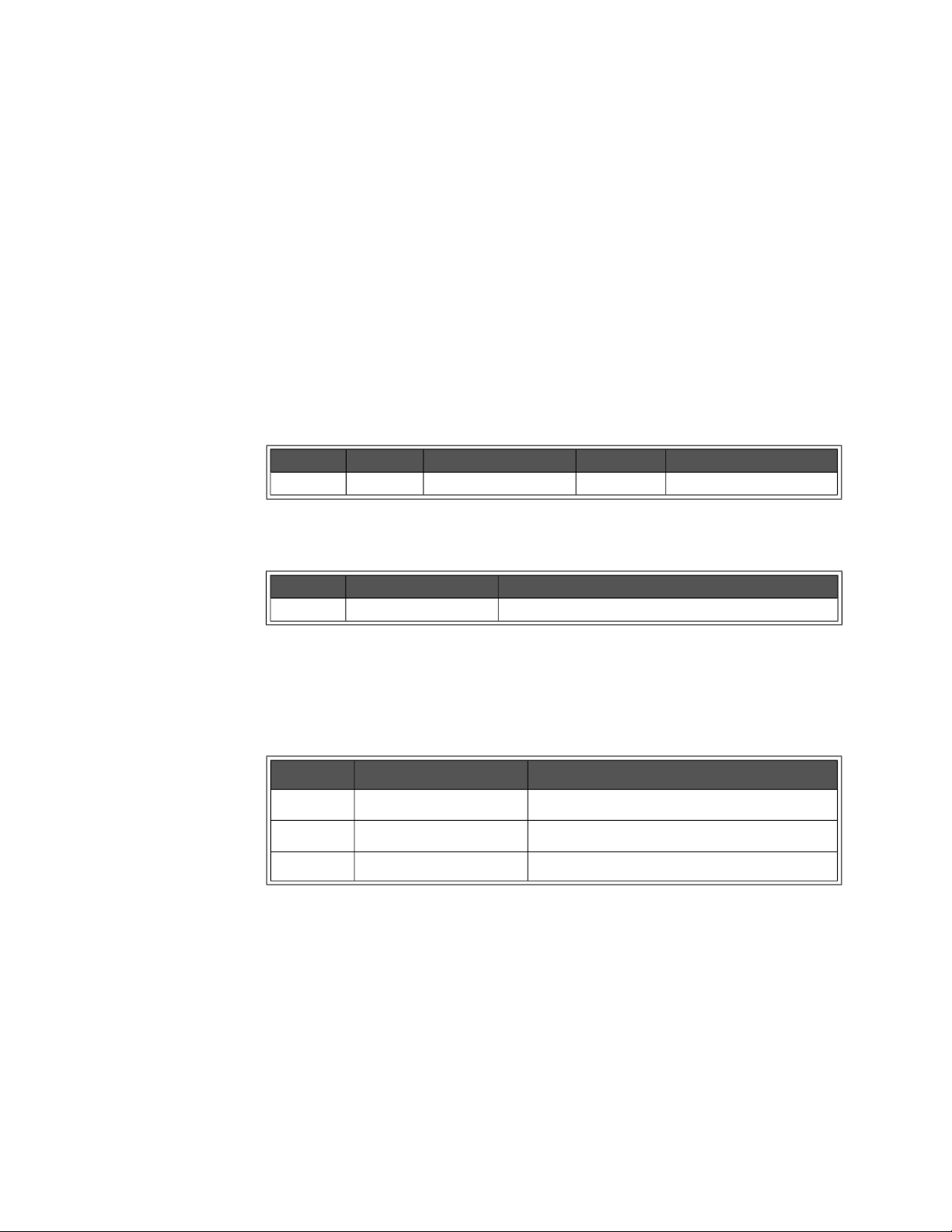
DISPlay Subsystem Programming the Enhanced Monitor
DISPlay[:WINDow]:STATe <state> DISPlay[:WINDow]:STATe?
DISPlay[:WINDow]:STATe sets the state of the mainframe’s display (ON, OFF,
AUTO).
mainframe is powered up.
places the Display in screen saver mode where the display will turn off when no
keys are pressed for 10 minutes.
DISPlay[:WINDow]:STATe? returns the state of mainframe’s display. The returned
data is a string (enumerated); either ON, OFF, or AUTO.
Parameters
Returned Data
ON is the default, and means the display is always on when the
OFF disables the display window and it is dark. AUTO
Name Type Range Default Description
<state> enum. ON,OFF,AUTO ON State of Display
Type Range Description
enum ON,OFF,AUTO State of Display
Error Conditions
The following table lists the most common error conditions and causes. Error
numbers and corresponding messages can be found using
SYSTem:ERRor?
query.
Number Message Probable Cause
-109 “Missing Parameter” The <state> parameter was omitted.
-221 “Settings Conflict” The mainframe’s power is off.
-224 “Illegal Parameter” The <state> parameter was not correct.
Reset Condition
At *RST, DISPlay[:WINDow]:STATe is set to ON.
Keysight E8402A, E8404A C-Size Mainframes User and Service Guide 65
Page 66
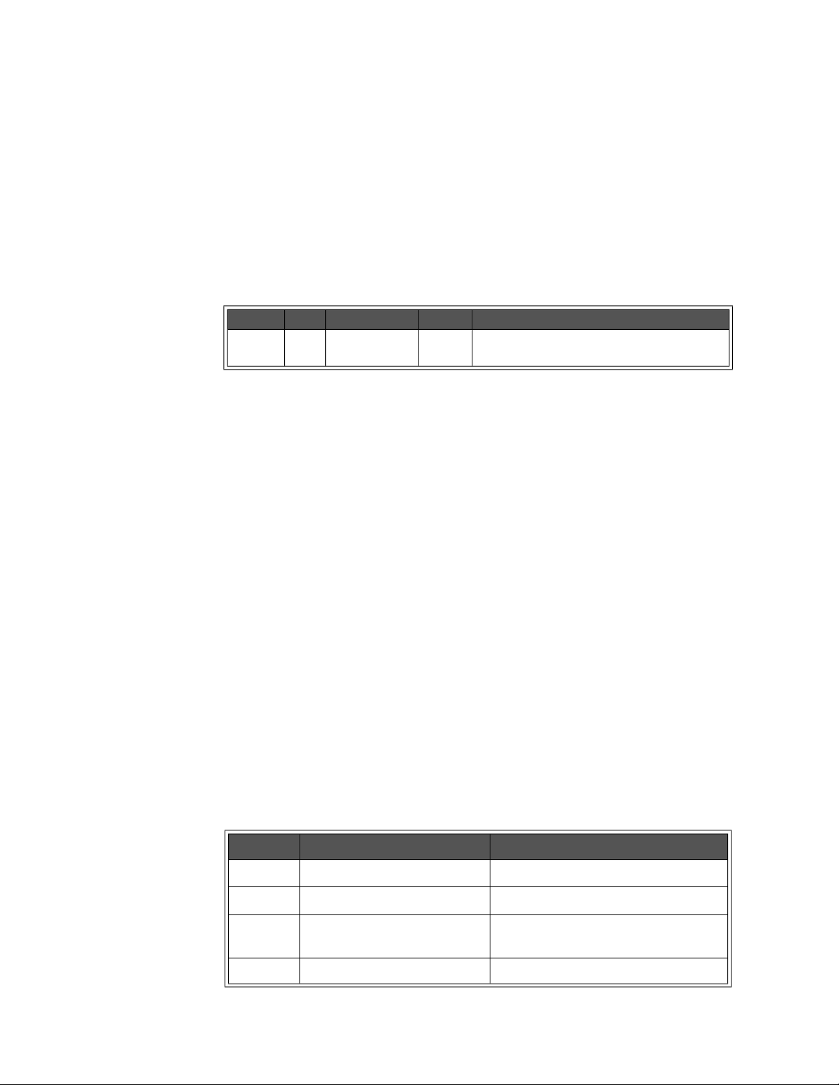
Programming the Enhanced Monitor DISPlay Subsystem
DISPlay[:WINDow]:TEXT[:DATA] <string>
DISPlay[:WINDow]:TEXT[:DATA] displays a user defined message string on the
mainframe’s display. The message remains on the display until a key is pressed,
the display window is changed programmatically, or the screen saver turns off
the display.
Parameters
Name Type Range Default Description
<string> string 186 characters none Message to display on screen. Can be any ASCII
character (decimal value 20 to 225).
Comments
– Four lines of text can be displayed. The display uses a proportional font;
line length can vary from 25 to 45 characters. The string will be clipped at
45 characters if there is not an embedded ‘\n’, or it will be clipped at 4
lines, or at 186 characters. There is no error generated if the string is
clipped. Text is white letters on a black background.)
– Embed a ‘\n’ to cause a second, third, or fourth line. For example, the
command
\nmessage capability
DISP:TEXT “this is a test\nof the immediate
.” executed from an RS-232 terminal will create
the following display:
this is a test
of the immediate
message capability.
– Pressing any front panel key (up/down arrow keys or
executing a
DISP:WIND command will remove the text.
ENTER key) or
Error Conditions
The following table lists the most common error conditions and causes. Error
numbers and corresponding messages can be found using
query.
Number Message Probable Cause
-128 “Numeric data not allowed” The <string> started with a number.
-148 “Character data not allowed” Quotation marks were left off.
SYSTem:ERRor?
-151 “Invalid string data” An embedded new line in the string instead
of a ‘\n’.
-221 “Settings Conflict” The mainframe’s power is off.
66 Keysight E8402A, E8404A C-Size Mainframes User and Service Guide
Page 67

DISPlay Subsystem Programming the Enhanced Monitor
Reset Condition
*RST removes text, and set the display screen to MMAin.
Example
The following is a Visual C example:
viPrintf(vi, “disp:text \”this is a test\nof the immediate\nmessage capability.\”\
n”)
Keysight E8402A, E8404A C-Size Mainframes User and Service Guide 67
Page 68
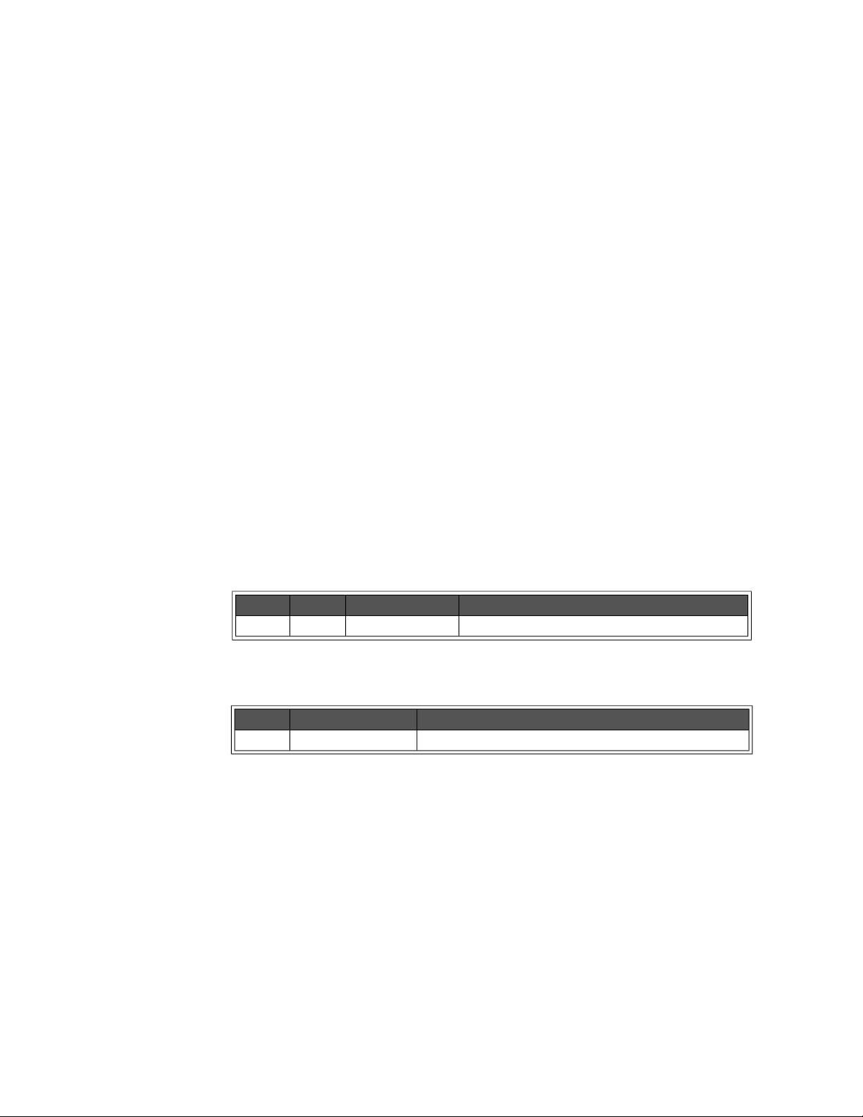
Programming the Enhanced Monitor FORMat Subsystem
FORMat Subsystem
The FORMat subsystem controls the TRACe data format.
Subsystem Syntax
:FORMat
:BORDer NORM|SWAP Sets the byte order of TRACe data.
:BORDer? Returns the byte order of the TRACe
data.
FORMat:BORDer <order> FORMat:BORDer?
FORMat:BORDer sets the byte order of the data returned by the TRACe
subsystem.
significant byte first.
NORMal is with most significant byte first. SWAPped is with least
FORMat:BORDer? returns the byte order of the data returned by the TRACe
subsystem.
Parameters
Name Type Range Description
<order> enum. NORM, SWAP Sets byte order for TRACe subsystem.
Returned Data
Type Range Description
enum. NORM, SWAP String description of byte order.
Comments
– Byte order is not stored in non-volatile memory. Programs requiring SWAP
order should include this command before reading TRACe data.
– Keysight VISA swaps the bytes in the definite block format of viQueryf in a
PC. Therefore, you should not use this command if you are using Keysight
VISA.
Reset Condition
At *RST, the byte order is reset to NORMal.
68 Keysight E8402A, E8404A C-Size Mainframes User and Service Guide
Page 69

HISTory Subsystem Programming the Enhanced Monitor
HISTory Subsystem
The history subsystem gives access to the enhanced monitor’s history-gathering
function.
Subsystem Syntax
:HISTory
:BLOWer
[:HISTogram]? <blower> Returns <blower> histogram data
:CURRent
:CMAXimum? <supply> Returns max. <supply> current since pwr-on.
[:HISTogram]? <supply> Returns <supply> current histogram data
:MAXimum? <supply> Returns maximum <supply> current.
:POWer
:CMAXimum? <supply> Returns max. <supply> power since pwr-on.
[:HISTogram]? <supply> Returns <supply> power histogram data.
:MAXimum? <supply> Returns maximum <supply> power.
:QUEue
:COUNt? Returns number of events in history queue.
[:FETCh]? <event index> Returns <number> history event from queue.
:RESet
[:ALL] Resets data in history subsystem to zero.
:BLOWer <blower> Resets data in <blower> history to zero.
:CURRent <supply> Resets data in <supply> current history to zero.
:POWer <supply> Resets data in <supply> power history to zero.
:QUEue Erases all data in history queue.
:TEMPerature <slot> Resets the data in <slot> history to be zero.
:VOLTage <supply> Resets data in <supply> voltage history to zero.
:TEMPerature
:CMAXimum? <slot> Returns max. <slot> temperature since pwr-on.
:CMINimum? <slot> Returns min. <slot> temperature since pwr-on.
[:HISTogram]? <slot> Returns for <slot> histogram data.
:MAXimum? <slot> Returns maximum <slot> temperature.
:MINimum? <slot> Returns minimum <slot> temperature.
:TIME
:LCALibration? Returns hr, min, sec since last calibration.
:LHReset? Returns hr, min, sec since last history reset.
:LTST? Returns hr, min, sec since last *TST.
:ON? Returns hr, min, sec since power-on.
:OPERating? Returns time mainframe has been operating.
:UNITs
[:TIME]<unit> Sets time units for history subsystem.
[:TIME]? Returns time units for history subsystem.
:VOLTage
:CMAXimum? <supply> Returns max. <supply> voltage since pwr-on.
:CMINimum? <supply> Returns min. <supply> voltage since pwr-on.
[:HISTogram]? <supply> Returns <supply> voltage histogram data.
:MAXimum? <supply> Returns maximum <supply> voltage.
:MINimum? <supply> Returns minimum <supply> voltage.
Keysight E8402A, E8404A C-Size Mainframes User and Service Guide 69
Page 70
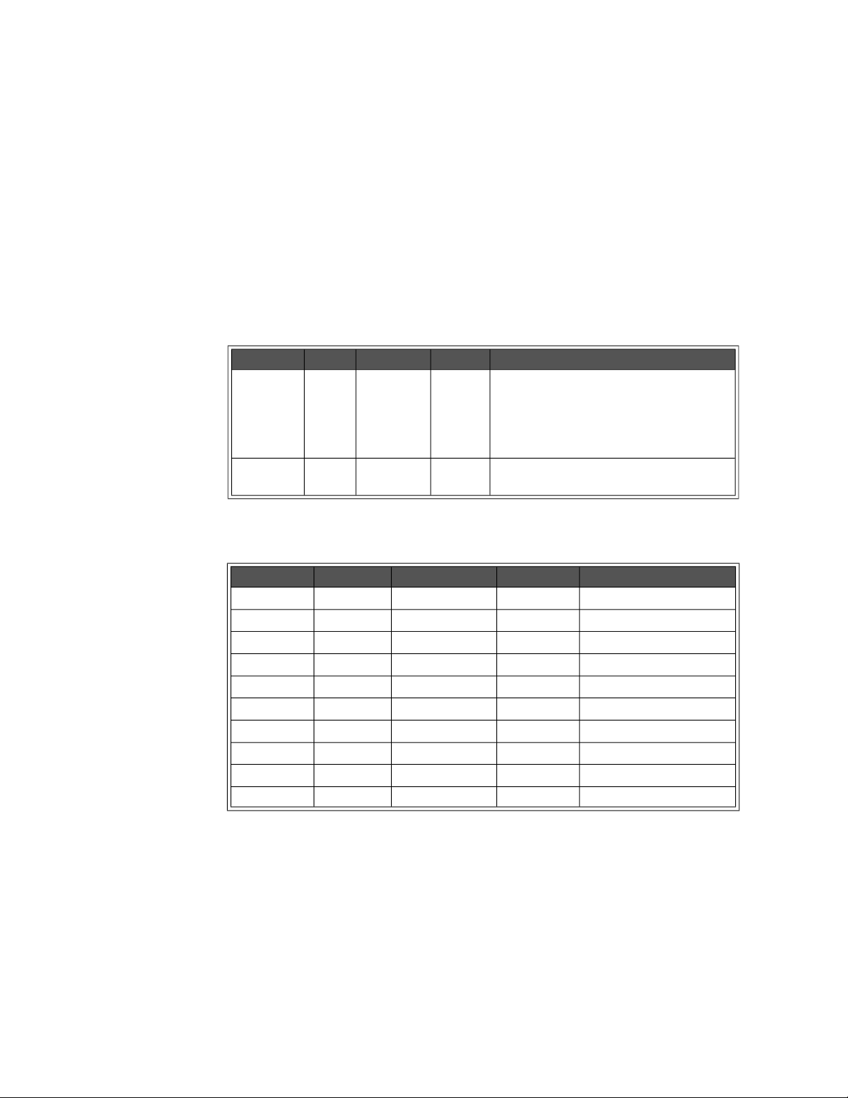
Programming the Enhanced Monitor HISTory Subsystem
HISTory:BLOWer[:HISTogram]? <blower>[,MIN|MAX]
HISTory:BLOWer[:HISTogram]? <blower> returns the histogram data for the
specified <blower>. Ten values are returned for the amount of time the
<blower>’s RPM level spent in ten different RPM ranges. Those RPM ranges can
be queried with the MIN and MAX optional parameter. The units of the time
values returned are HOURs by default, but can be changed with the
HISTory:UNIT[:TIME] command.
Parameters
Name Type Range Default Description
<blower> enum. BLOWer1,
BLOWer2,
BLOWer3
optional
parameter
enum. MIN, MAX none Returns the maximums or minimums of the
none Selects the fan whose RPM histogram is
desired. BLOWer1 is the main cooling fan,
BLOWer2 is the Power Supply cooling fan,
BLOWer3 is a second Power Supply cooling
fan on the Keysight E8404A mainframes.
RPM ranges.
Returned Data
Type Range Default Description
<range1> int32 0-2147483647 none lowest RPM range.
<range2> int32 0-2147483647 none second RPM range.
<range3> int32 0-2147483647 none third RPM range.
<range4> int32 0-2147483647 none fourth RPM range.
<range5> int32 0-2147483647 none fifth RPM range.
<range6> int32 0-2147483647 none sixth RPM range.
<range7> int32 0-2147483647 none seventh RPM range.
<range8> int32 0-2147483647 none eighth RPM range.
<range9> int32 0-2147483647 none ninth RPM range.
<range10> int32 0-2147483647 none highest RPM range.
Comments
– HIST:BLOW? BLOW1 returns 10 time values, units set/queried by
HIST:UNIT.
– HIST:BLOW? BLOW1,MAX returns 10 values representing the maximums
for each RPM range.
70 Keysight E8402A, E8404A C-Size Mainframes User and Service Guide
Page 71
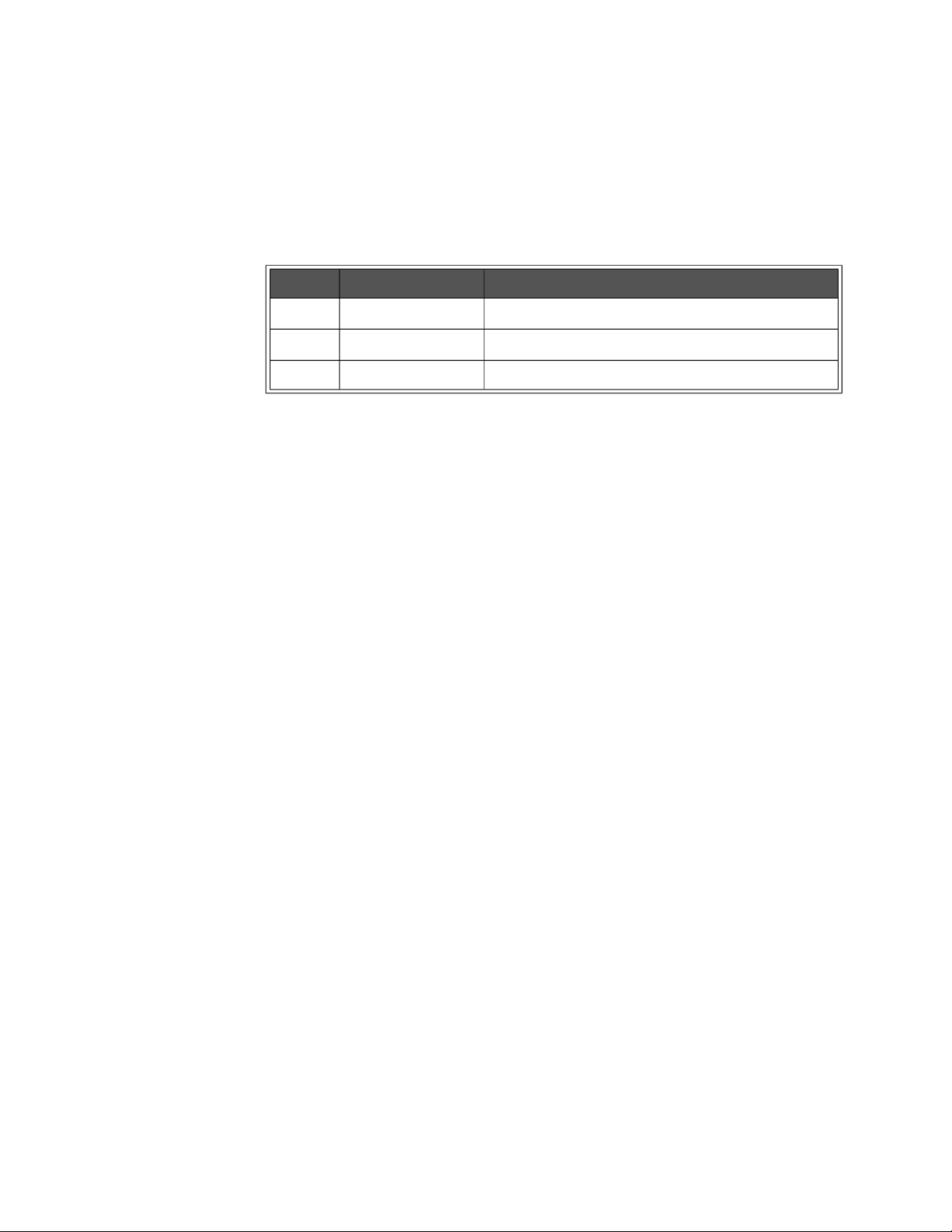
HISTory Subsystem Programming the Enhanced Monitor
Error Conditions
The following table lists the most common error conditions and causes. Error
numbers and corresponding messages can be found using
SYSTem:ERRor?
query.
Number Message Probable Cause
-109 “Missing Parameter” The <blower> parameter was omitted.
-224 “Illegal Parameter” The <blower> or optional parameter not correct.
-311 “Memory error” The historical data’s memory is not available.
Reset Condition
*RST has no effect on the HISTory subsystem.
Related Commands
HISTory:RESet:BLOWer, HISTory:UNITs[:TIME]
Keysight E8402A, E8404A C-Size Mainframes User and Service Guide 71
Page 72
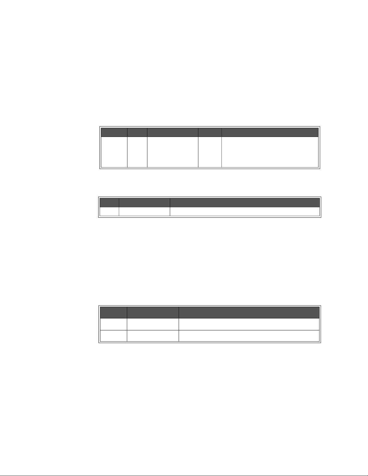
Programming the Enhanced Monitor HISTory Subsystem
HISTory:CURRent:CMAXimum? <supply>
HISTory:CURRent:CMAXimum? <supply> returns a single floating point number
for the maximum amperage (in milliamps) measured by the Enhanced Monitor
for the <supply> since power-on of the mainframe.
Parameters
Name Type Range Default Description
<supply> enum. P5, P12, N12, P24,
N24, N5PT2, N2
Returned Data
Type Range Description
float Maximum current (in amperes) for specified power supply.
none Selects the power supply for the
current maximum request. P5 is positive
5 Vdc supply, N12 is negative 12 Vdc
supply, etc.
Comments
– These maximums can be reset by powering the mainframe off and then
powering it back on.
Error Conditions
The following table lists the most common error conditions and causes. Error
numbers and corresponding messages can be found using
SYSTem:ERRor?
query.
Number Message Probable Cause
-221 “Settings Conflict” The power supply doesn’t support current measurements.
-224 “Illegal Parameter” The <supply> parameter was not correct.
Reset Condition
*RST has no effect on the HISTory subsystem.
Related Commands
HISTory:CURRent:MAXimum?, HISTory:CURRent:[HISTogram]?
72 Keysight E8402A, E8404A C-Size Mainframes User and Service Guide
Page 73
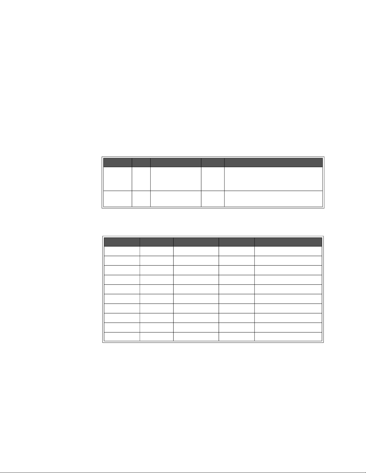
HISTory Subsystem Programming the Enhanced Monitor
HISTory:CURRent[:HISTogram]? <supply>[,MIN|MAX]
HISTory:CURRent[:HISTogram]? <supply> returns the histogram data held for the
specified <supply>. Ten values are returned for the amount of time the
<supply>’s current spent in ten different current ranges. Those current ranges
can be queried with the MIN and MAX optional parameter. The units of the time
values returned are HOURs by default, but can be changed with the
HISTory:UNIT[:TIME] command. The units returned for current ranges queried
with the MIN or MAX parameters are integer values in milliamps.
Parameters
Name Type Range Default Description
<supply> enum P5, P12, N12, P24,
N24, N5PT2, N2
optional
parameter
enum MIN, MAX none Returns the minimums or maximums of
none Selects the power supply whose current
histogram is desired. P5 is +5 Vdc supply,
N12 is -12 Vdc supply, etc.
the current ranges in milliamps.
Returned Data
Type Range Default Description
<range1> int32 0-2147483647 none lowest current range.
<range2> int32 0-2147483647 none second current range.
<range3> int32 0-2147483647 none third current range.
<range4> int32 0-2147483647 none fourth current range.
<range5> int32 0-2147483647 none fifth current range.
<range6> int32 0-2147483647 none sixth current range.
<range7> int32 0-2147483647 none seventh current range.
<range8> int32 0-2147483647 none eighth current range.
<range9> int32 0-2147483647 none ninth current range.
<range10> int32 0-2147483647 none highest current range.
Comments
– HIST:CURR? P5 returns 10 time values for the +5V supply.
–
HIST:CURR? P5,MAX returns 10 values representing the maximum currents
in each current range in milliamps.
Keysight E8402A, E8404A C-Size Mainframes User and Service Guide 73
Page 74

Programming the Enhanced Monitor HISTory Subsystem
Error Conditions
The following table lists the most common error conditions and causes. Error
numbers and corresponding messages can be found using
SYSTem:ERRor?
query.
Number Message Probable Cause
-109 “Missing Parameter” The <supply> parameter was omitted.
-224 “Illegal Parameter” The <supply> or optional parameter not correct.
-221 “Settings Conflict” Power supply doesn’t support current measurements.
-311 “Memory error” The historical data’s memory is not available.
Reset Condition
*RST has no effect on the HISTory subsystem.
Related Commands
HISTory:CURRent:MAXimum?, HISTory:RESet:CURRent, HISTory:UNITs[:TIME]
74 Keysight E8402A, E8404A C-Size Mainframes User and Service Guide
Page 75

HISTory Subsystem Programming the Enhanced Monitor
HISTory:CURRent:MAXimum? <supply>
HISTory:CURRent:MAXimum? <supply> returns a single floating point number for
the maximum amperage that has occurred to the <supply> since manufacture of
the mainframe, or the most recent
Parameters
Name Type Range Default Description
<supply> enum P5, P12, N12, P24,
N24, N5PT2, N2
Returned Data
Type Range Description
float Maximum current (in amperes) for specified power supply.
HIST:RES:CURR or HIST:RES:ALL.
none Selects the power supply for the
maximum amperage request. P5 is
positive 5 Vdc supply, N12 is negative
12 Vdc supply, etc.
Comments
– The maximum amperage tracking can be zeroed by the HISTory:RESet
commands.
Error Conditions
The following table lists the most common error conditions and causes. Error
numbers and corresponding messages can be found using
SYSTem:ERRor?
query.
Number Message Probable Cause
-221 “Settings Conflict” The power supply doesn’t support current measurements.
-224 “Illegal Parameter” The <supply> parameter was not correct.
-311 “Memory error” The historical data’s memory is not available.
Reset Condition
A *RST has no effect on the HISTory subsystem.
Related Commands
HISTory:CURRent:CMAXimum?, HISTory:CURRent:[HISTogram]?,
HISTory:RESet:CURRent, HISTory:RESet[:ALL]
Keysight E8402A, E8404A C-Size Mainframes User and Service Guide 75
Page 76

Programming the Enhanced Monitor HISTory Subsystem
HISTory:POWer:CMAXimum? <supply>
HISTory:POWer:CMAXimum? <supply> returns a single floating point number for
the maximum wattage measured by the Enhanced Monitor for the <supply>
since power-on of the mainframe.
Parameters
Name Type Range Default Description
<supply> enum P5, P12, N12, P24,
N24, N5PT2, N2,
TOTal
Returned Data
Type Range Description
float Maximum power (in watts) for specified power supply.
none Selects the power supply for the current
maximum request. P5 is positive 5 Vdc
supply, N12 is negative 12 Vdc supply,
etc.
Comments
– These maximums can be reset by powering the mainframe off and then
powering it back on.
Error Conditions
The following table lists the most common error conditions and causes. Error
numbers and corresponding messages can be found using
SYSTem:ERRor?
query.
Number Message Probable Cause
-221 “Settings Conflict” The power supply doesn’t support current measurements.
-224 “Illegal Parameter” The <supply> parameter was not correct.
Reset Condition
A *RST has no effect on the HISTory subsystem.
Related Commands
HISTory:POWer:MAXimum?, HISTory:POWer:[HISTogram]?
76 Keysight E8402A, E8404A C-Size Mainframes User and Service Guide
Page 77

HISTory Subsystem Programming the Enhanced Monitor
HISTory:POWer[:HISTogram]? <supply>[,MIN|MAX]
HISTory:POWer[:HISTogram]? <supply> returns the histogram data held for the
<supply>. Ten values are returned for the amount of time the <supply>’s power
spent in ten different power ranges. Those power ranges can be queried with the
MIN and MAX optional parameter. The units of the time values returned are
HOURs by default, but can be changed with the
command.The units returned for power ranges queried with the
parameters are integer values in milliwatts.
Parameters
Name Type Range Default Description
<supply> enum. P5, P12, N12, P24,
N24, N5PT2, N2,
TOTal
optional
parameter
enum. MIN, MAX none Returns the maximum or minimum of the
none Selects the power supply whose power
HISTory:UNIT[:TIME]
MIN or MAX
histogram is desired. P5 is +5 Vdc
supply, N12 is -12 Vdc supply, etc.
power range in milliwatts.
Returned Data
Type Range Default Description
<range1> int32 0-2147483647 none lowest power range.
<range2> int32 0-2147483647 none second power range.
<range3> int32 0-2147483647 none third power range.
<range4> int32 0-2147483647 none fourth power range.
<range5> int32 0-2147483647 none fifth power range.
<range6> int32 0-2147483647 none sixth power range.
<range7> int32 0-2147483647 none seventh power range.
<range8> int32 0-2147483647 none eighth power range.
<range9> int32 0-2147483647 none ninth power range.
<range10> int32 0-2147483647 none highest power range.
Comments
– HIST:POW? P5 returns 10 time values for +5V supply.
–
HIST:POW? P5,MAX returns 10 values representing the maximum power
for each power range in milliwatts.
Keysight E8402A, E8404A C-Size Mainframes User and Service Guide 77
Page 78

Programming the Enhanced Monitor HISTory Subsystem
Error Conditions
The following table lists the most common error conditions and causes. Error
numbers and corresponding messages can be found using
SYSTem:ERRor?
query.
Number Message Probable Cause
-224 “Illegal Parameter” The <supply> or optional parameter not correct.
-109 “Missing Parameter” The <supply> parameter was omitted.
-311 “Memory error” The historical data’s memory is not available.
-221 “Settings Conflict” The power supply doesn’t support power
measurements.
Reset Condition
A *RST has no effect on the HISTory subsystem.
Related Commands
HISTory:POWer:MAXimum?, HISTory:RESet:POWer, HISTory:UNITs[:TIME]
78 Keysight E8402A, E8404A C-Size Mainframes User and Service Guide
Page 79

HISTory Subsystem Programming the Enhanced Monitor
HISTory:POWer:MAXimum? <supply>
HISTory:POWer:MAXimum? <supply> returns a single floating point number for
the maximum wattage measured by the Enhanced Monitor for the <supply>
since either manufacture of the mainframe or the most recent
HIST:RES:ALL.
Parameters
Name Type Range Default Description
<supply> enum P5, P12, N12, P24,
N24, N5PT2, N2,
TOTal
none Selects the power supply for the
maximum wattage request. P5 is
positive 5 Vdc supply, N12 is negative
12 Vdc supply, etc.
Returned Data
HIST:RES:POW or
Type Range Description
float Maximum current (in amperes) for specified power supply.
Comments
– The maximum wattage tracking can be zeroed by the HISTory:RESet
commands.
Error Conditions
The following table lists the most common error conditions and causes. Error
numbers and corresponding messages can be found using
query.
Number Message Probable Cause
-109 “Missing parameter” You must include the <supply> parameter.
-221 “Settings Conflict” The power supply doesn’t support power
measurements.
-224 “Illegal Parameter” The <supply> parameter was not correct.
-311 “Memory error” The historical data’s memory is not available.
SYSTem:ERRor?
Reset Condition
A *RST has no effect on the HISTory subsystem.
Keysight E8402A, E8404A C-Size Mainframes User and Service Guide 79
Page 80

Programming the Enhanced Monitor HISTory Subsystem
Related Commands
HISTory:POWer:CMAXimum?, HISTory: POWer:[HISTogram]?, HISTory:RESet:
POWer, HISTory:RESet[:ALL]
80 Keysight E8402A, E8404A C-Size Mainframes User and Service Guide
Page 81
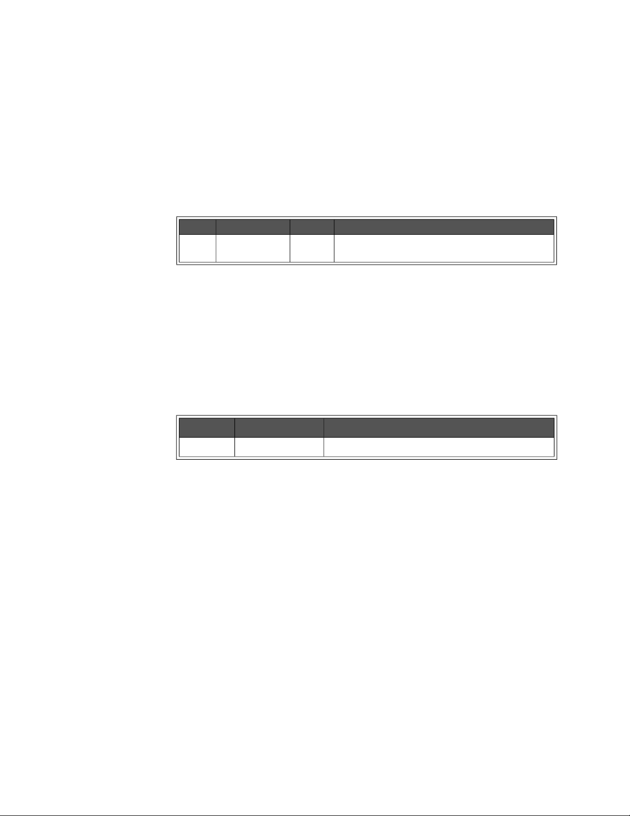
HISTory Subsystem Programming the Enhanced Monitor
HISTory:QUEue:COUNt?
HISTory:QUEue:COUNt? returns the number of history events in the history
queue.The maximum number of events capable of being stored in the history
queue varies from 500 to 1000 depending on the type of events stored.
Returned Data
Type Range Default Description
uint16 0 through 1000 none The count of history events presently in the history
queue.
Comments
– HIST:QUE:COUN? determines the maximum number accepted by the
HIST:QUE:FETC? command.
Error Conditions
The following table lists the most common error conditions and causes. Error
numbers and corresponding messages can be found using
SYSTem:ERRor?
query.
Number Message Probable Cause
-311 “Memory error” The history queue’s memory is not available.
Reset Condition
A *RST has no effect on the HISTory subsystem.
Related Commands
HISTory:QUEue[:FETCh]?, HISTory:RESet:QUEue, HISTory:UNITs[:TIME],
HISTory:UNITs[:TIME]?
Keysight E8402A, E8404A C-Size Mainframes User and Service Guide 81
Page 82
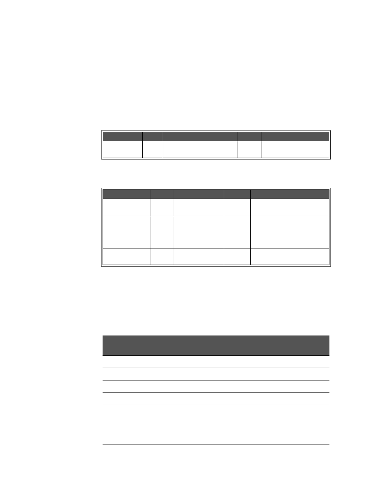
Programming the Enhanced Monitor HISTory Subsystem
HISTory:QUEue[:FETCh]? <event index>
HISTory:QUEue[:FETCh]? <event index> returns a history event from the history
queue corresponding to <event index>. The queue is in chronological order, with
the oldest event in the index as <event index> number 1.
Parameters
Name Type Range Default Description
<event index> uint16 1 through the value returned
from HIST:QUEue:COUNt
Returned Data
Type Range Default Description
<event type> int16 0 to 127 none An number associated with the
<time stamp> uint32 0 to 4294967295 none Amount of time since
<event string> string Event string associated with the
none The index of the history
event requested.
logged event.
manufacture that the event
occurred. Units are set with
HIST:UNIT
logged event.
Comments
– Many types of events are logged: amount of time on; wake-up test failures;
temperature, current, power, voltage, fan warning events and conditions;
calibration occurrences and results; test occurrences and results; and all
history reset events. The event strings return in the language selected on
the display.
Event
Number
0 Mainframe powered off.
1 History queue was reset/cleared
3 Unexpected power-down occurred. Data was lost.
4 Power-on test failure. Result given in the event string. Refer to next comment.
5 - 17 Front slot temperature over limit. Event Number 5 is slot 0; 17 is slot 12. Limit is
18 - 30 Middle slot temperature was over the limit. Event Number 18 is slot 0; 30 is slot
Description
given in the event string.
12. Limit is given in the event string.
82 Keysight E8402A, E8404A C-Size Mainframes User and Service Guide
Page 83

HISTory Subsystem Programming the Enhanced Monitor
Event
Number
31 - 43 Rear slot temperature was over the limit. Event Number 31 is slot 0; 43 is slot 12.
44 Ambient temperature was over limit. Limit given in the event string.
45 Power supply temperature was over limit.
47 - 53 Voltage was over upper limit. Event 47 is +5V supply, ... +12V, -12V, +24V, -24V,
54 - 60 Voltage was under lower limit. Event 54 is +5V supply, ... +12V, -12V, +24V, -24V,
61 - 67 Current was over limit. Limit given in the event string. Event 61 is +5V supply, ...
68 Total power was over limit. Limit given in the event string.
69 - 71 Fan was over upper limit. Event 69 is BLOW1, 70 is BLOW2, 71 is BLOW3
72 - 74 Fan was under lower limit. Event 72 is BLOW1, 73 is BLOW2, 74 is BLOW3
75 Calibration or test occurred. Kind and result are given in event string.
76 Reset of history data occurred. Event string specifies which one.
Description
Limit is given in the event string.
-5.2V, and event 53 is -2V supply.
-5.2V, and event 60 is -2V supply.
+12V, -12V, +24V, -24V, -5.2V, and event 67 is -2V supply.
77 VXI SYSRESET occurred.
78 Queue is full and event(s) are lost.
79 Maintenance timer warning occurred.
– Power-on test failures (Event number 4) include a hex value (0000 to FFFF)
which is a sum of the failures that occurred. The following list indicates the
possible power-on test failures:
-- Bit 0 set: non-volatile timing data lost or corrupted.
-- Bit 1 set: non-volatile power supply data lost or corrupted.
-- Bit 2 set: non-volatile maximum measurements lost or corrupted.
-- Bit 3 set: non-volatile minimum measurements lost or corrupted.
-- Bit 4 set: non-volatile user settings lost or corrupted.
-- Bit 5 set: non-volatile RS-232 settings lost or corrupted.
-- Bit 6 set: non-volatile calibration settings lost or corrupted.
-- Bit 7 set: non-volatile histogram data lost or corrupted.
-- Bit 10 set: non-volatile history queue data lost or corrupted.
-- Bit 12 set: wake-up ROM test failed.
Keysight E8402A, E8404A C-Size Mainframes User and Service Guide 83
Page 84
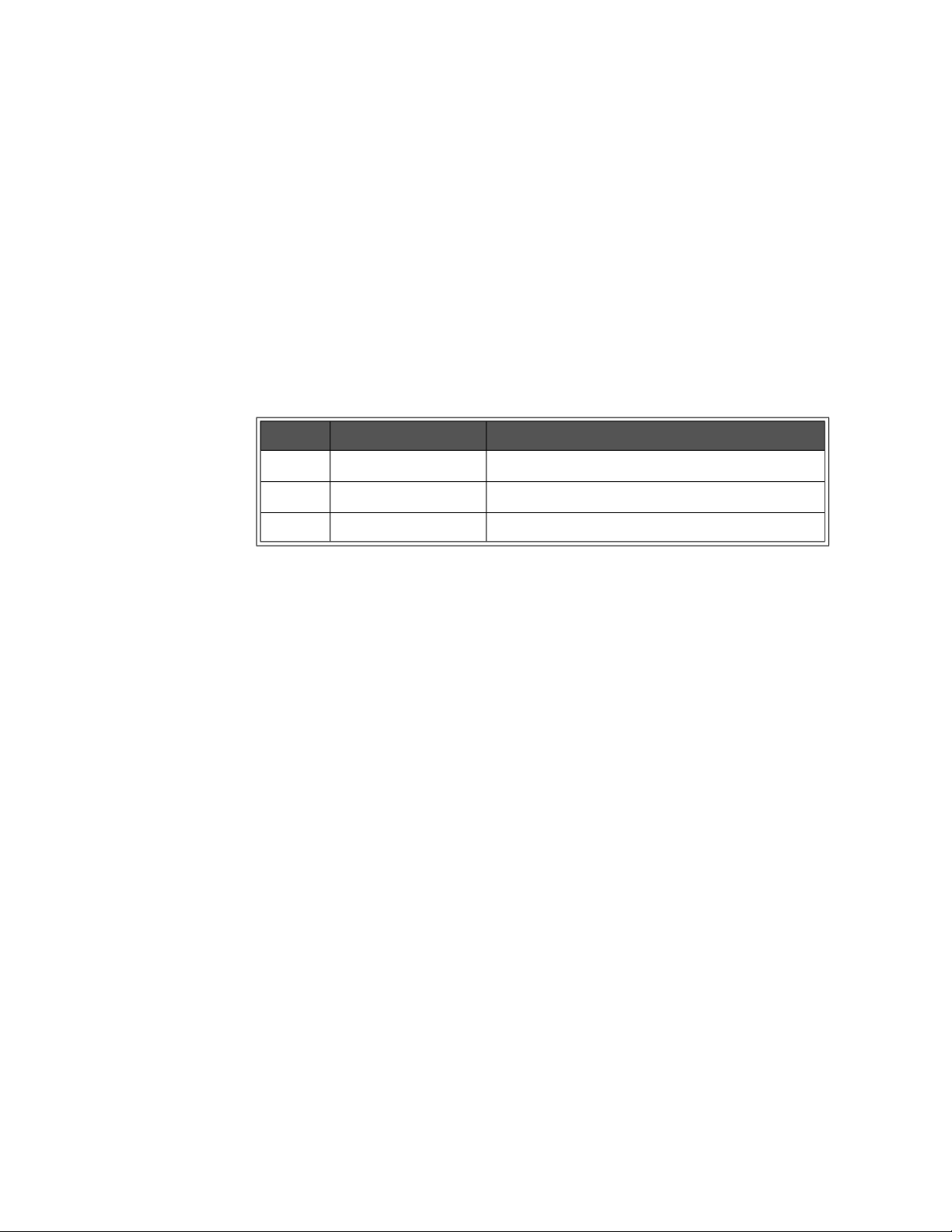
Programming the Enhanced Monitor HISTory Subsystem
-- Bit 13 set: wake-up RAM test failed.
-- Bit 14 set: wake-up VXI Communication test failed.
-- Bit 15 set: unexpected power failure occurred, some data loss likely.
– Once an event is logged, it stays there. For example, an event at event
index 7 will always be at event index 7 until the queue is reset.
Error Conditions
The following table lists the most common error conditions and causes. Error
numbers and corresponding messages can be found using
query.
Number Message Probable Cause
-109 “Missing parameter” You must include the <event index> parameter.
-222 “Data out of range” The <event number> was beyond HIST:QUE:COUN.
-311 “Memory error” The history queue’s memory is not available.
SYSTem:ERRor?
Reset Condition
A *RST has no effect on the HISTory subsystem.
Related Commands
HISTory:QUEue:COUNt?, HISTory:RESet:QUEue, HISTory:UNITs[:TIME],
HISTory:UNITs[:TIME]?
84 Keysight E8402A, E8404A C-Size Mainframes User and Service Guide
Page 85

HISTory Subsystem Programming the Enhanced Monitor
HISTory:RESet[:ALL] HISTory:RESet:BLOWer [<blower>] HISTory:RESet:CURRent [<supply>] HISTory:RESet:POWer [<supply>] HISTory:RESet:QUEue HISTory:RESet:TEMPerature [<slot>] HISTory:RESet:VOLTage [<supply>]
The HISTory:RESet commands erase all data being held by the HISTory
subsystem: histograms, minimum/maximum values, and the history queue. For
example,
historical data stored for the specified <blower>,
amperage historical data for the specified <supply>, etc. The
command does not erase stripchart data. The following table describes the
commands and their parameters. These commands are not allowed while the
mainframe’s power is off.
HIST:RES:ALL erases all historical data; HIST:RES:BLOW erases the
HIST:RES:CURR erases the
HISTory:RESet
Parameters
Command Parameter(s) Range Default Description
[:ALL] Erases all historical data. The history queue retains two entries (ALL
HISTORY RESET, and QUEUE RESET) marking the time between
manufacture and the HISTory:RESet. These commands are not
allowed while the mainframe’s power is off.
:BLOW <blower> BLOWer1,
BLOWer2,
BLOWer3
:CURR <supply> P5, P12, N12, P24,
N24, N5PT2, N2, P5STby
:POW <supply> P5, P12, N12, P24,
N24, N5PT2, N2, TOTal
:QUE Erases all the events stored in the history queue. One event is put in
:TEMP <slot> OUT0…OUT12,
DELTa0…DELTa12,
AMBient
PSUPply
:VOLT <supply> P5, P12, N12, P24,
N24, N5PT2, N2
none Selects the fan whose historical data is to be erased. BLOWer1 is the
main cooling fan, BLOWer2 is the Power Supply cooling fan,
BLOWer3 is a second Power Supply cooling fan on the Keysight
E8404A mainframes.
none Erases the amperage historical data for the selected <supply>.
Selects the power supply whose historical data is to be zeroed. P5
is positive 5 Vdc supply, N12 is negative 12 Vdc supply, etc.
none Erases the wattage historical data for the <supply>. Selects the
power supply whose historical data is to be zeroed. P5 is positive 5
Vdc supply, N12 is negative 12 Vdc supply, etc.
the history queue on this command: an event logging the time since
manufacture of the mainframe until the HIST:RES:QUE command.
This is a completely destructive command. There is no retrieving the
history queue. It is primarily needed if the history queue has filled up.
none Absolute Slot Temperature Histogram
Delta Slot Temperature Histogram
Ambient Temperature Histogram
Power Supply Temperature Histogram
none Erases the voltage historical data for the selected <supply>.
P5 is positive 5 Vdc supply, N12 is negative 12 Vdc supply, etc.
Keysight E8402A, E8404A C-Size Mainframes User and Service Guide 85
Page 86
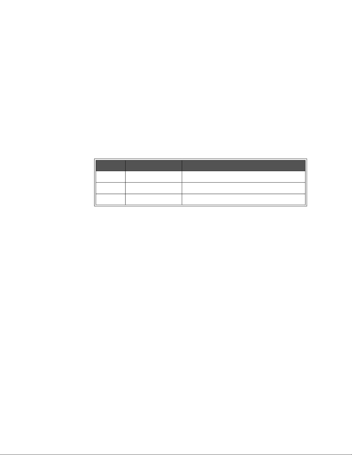
Programming the Enhanced Monitor HISTory Subsystem
Comments
– If a parameter is left off, then all the historical data for all parameters of
that command is erased. For example, if the <blower> parameter is left off
of the
HIST:RES:BLOW command, then ALL of the BLOWer historical data
is erased.
– These commands are not allowed while the mainframe’s power is off.
Error Conditions
The following table lists the most common error conditions and causes. Error
numbers and corresponding messages can be found using
query.
Number Message Probable Cause
-221 “Settings Conflict” The mainframe’s power is off.
-224 “Illegal Parameter” The parameter was not correct.
SYSTem:ERRor?
-311 “Memory error” The historical data’s memory is not available.
Reset Condition
A *RST has no effect on the HISTory subsystem.
86 Keysight E8402A, E8404A C-Size Mainframes User and Service Guide
Page 87
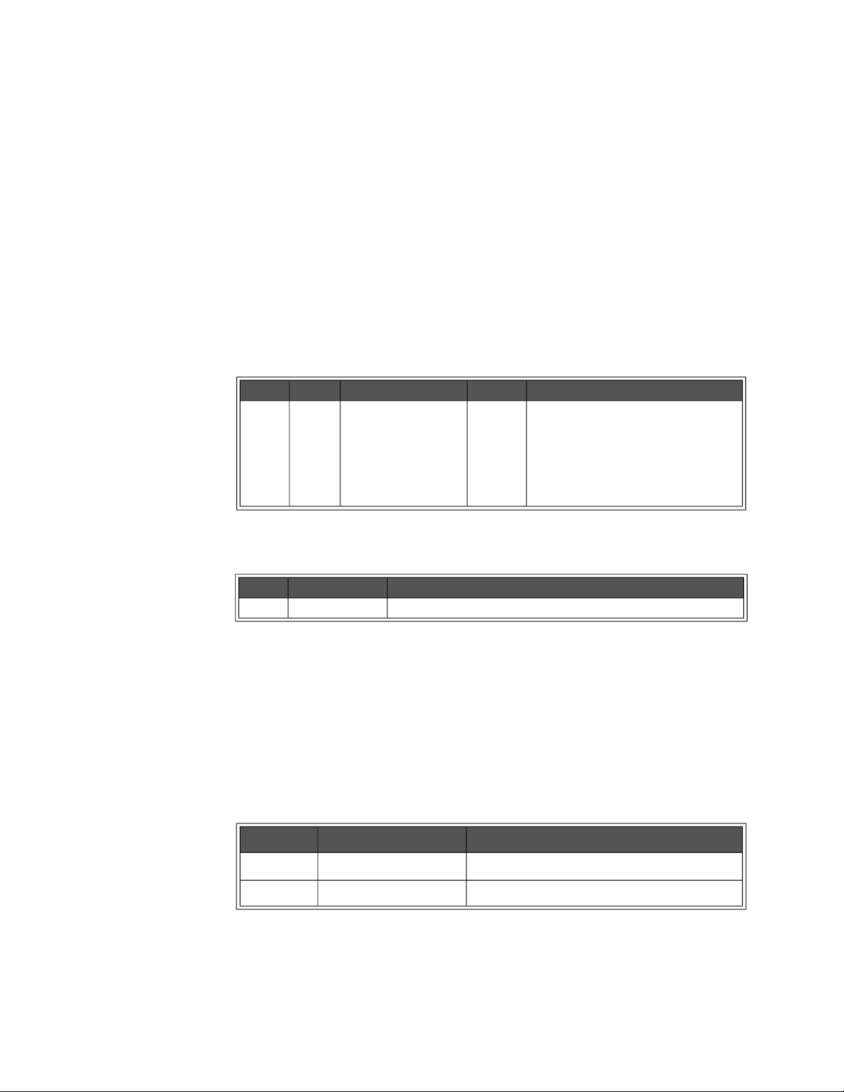
HISTory Subsystem Programming the Enhanced Monitor
HISTory:TEMPerature:CMAXimum? <slot> HISTory:TEMPerature:CMINimum? <slot>
HISTory:TEMPerature:CMAXimum? <slot> returns a single floating point number
for the maximum temperature measured by the Enhanced Monitor for the <slot>
parameter since power-on of the mainframe.
HISTory:TEMPerature:CMINimum? <slot> returns a single floating point number
for the minimum temperature measured by the Enhanced Monitor for the <slot>
parameter since power-on of the mainframe.
Parameters
Name Type Range Default Description
<slot> enum. OUT0…OUT12,
DELTa0…DELTa12,
AMBient
none Exhaust temperature for slots 0 - slot
12
Temperature change above the ambient
temperature for slots0 - slot 12
Entrance air temperature
Returned Data
Type Range Description
float Minimum or maximum temperature.
Comments
– These maximums/minimums can be reset by powering the mainframe off
and then powering it back on.
Error Conditions
The following table lists the most common error conditions and causes. Error
numbers and corresponding messages can be found using
SYSTem:ERRor?
query.
Number Message Probable Cause
-109 “Missing parameter” You must include the <slot> parameter.
-224 “Illegal Parameter” The <slot> parameter was not correct.
Reset Condition
A *RST has no effect on the HISTory subsystem.
Keysight E8402A, E8404A C-Size Mainframes User and Service Guide 87
Page 88

Programming the Enhanced Monitor HISTory Subsystem
Related Commands
HISTory:TEMPerature:MAXimum?, HISTory:TEMPerature:MINimum?,
HISTory:TEMPerature:[HISTogram]?
88 Keysight E8402A, E8404A C-Size Mainframes User and Service Guide
Page 89
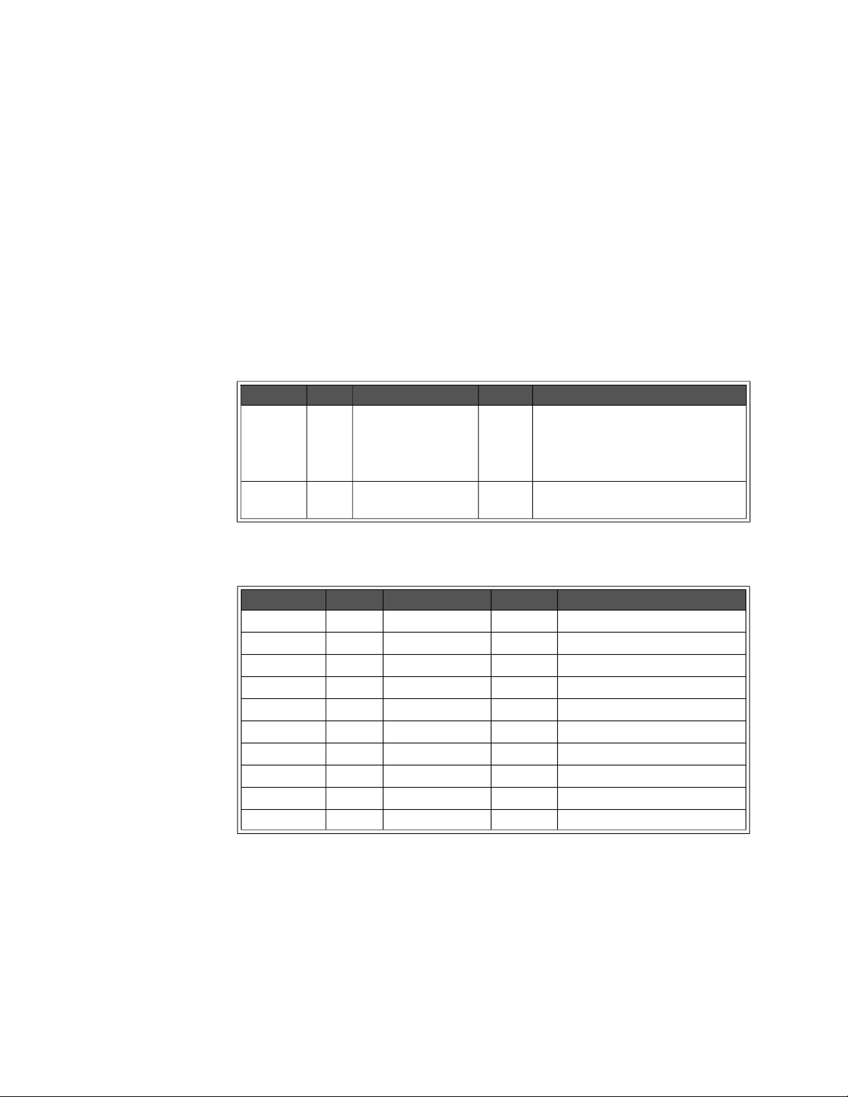
HISTory Subsystem Programming the Enhanced Monitor
HISTory:TEMPerature[:HISTogram]? <slot>[,MIN|MAX]
HISTory:TEMPerature[:HISTogram]? <slot> returns the histogram data held for the
specified <slot>. Ten values are returned for the amount of time the <slot>’s
temperature spent in ten different temperature ranges. Those temperature
ranges can be queried with the MIN and MAX optional parameter. The units of
the time values returned are HOURs by default, but can be changed with the
HISTory:UNIT[:TIME] command. The units returned for temperature ranges
queried with the
degree Celsius (0.x
Parameters
Name Type Range Default Description
<slot> enum. OUT0…OUT12,
optional
parameter
MIN or MAX parameters are an integer values in tenths of a
C).
none Absolute Slot Temperature
DELTa0…DELTa12,
AMBient
PSUPply
enum. MIN, MAX none Returns the maximums or minimums of
Delta Slot Temperature Histogram
Ambient Temperature Histogram
Power Supply Temperature
the temperature ranges.
Returned Data
Type Range Default Description
<range1> int32 0-2147483647 none lowest temperature range.
<range2> int32 0-2147483647 none second temperature range.
<range3> int32 0-2147483647 none third temperature range.
<range4> int32 0-2147483647 none fourth temperature range.
<range5> int32 0-2147483647 none fifth temperature range.
<range6> int32 0-2147483647 none sixth temperature range.
<range7> int32 0-2147483647 none seventh temperature range.
<range8> int32 0-2147483647 none eighth temperature range.
<range9> int32 0-2147483647 none ninth temperature range.
<range10> int32 0-2147483647 none highest temperature range.
Comments
– HIST:TEMP? OUT2 returns 10 time values for the exhaust temperature of
slot 2, units set/queried by HIST:UNIT.
–
HIST:TEMP? OUT2,MAX returns 10 temperatures that returns the
maximums for each temperature range in tenths of a degree Celsius (0.x
C) for slot 2.
Keysight E8402A, E8404A C-Size Mainframes User and Service Guide 89
Page 90

Programming the Enhanced Monitor HISTory Subsystem
Error Conditions
The following table lists the most common error conditions and causes. Error
numbers and corresponding messages can be found using
SYSTem:ERRor?
query.
Number Message Probable Cause
-109 “Missing Parameter” The <slot> parameter was omitted.
-224 “Illegal Parameter” The <slot> or optional parameter were not correct.
-311 “Memory error” The historical data’s memory is not available.
Reset Condition
A *RST has no effect on the HISTory subsystem.
Related Commands
HISTory:RESet:CURRent, HISTory:UNITs[:TIME]
90 Keysight E8402A, E8404A C-Size Mainframes User and Service Guide
Page 91
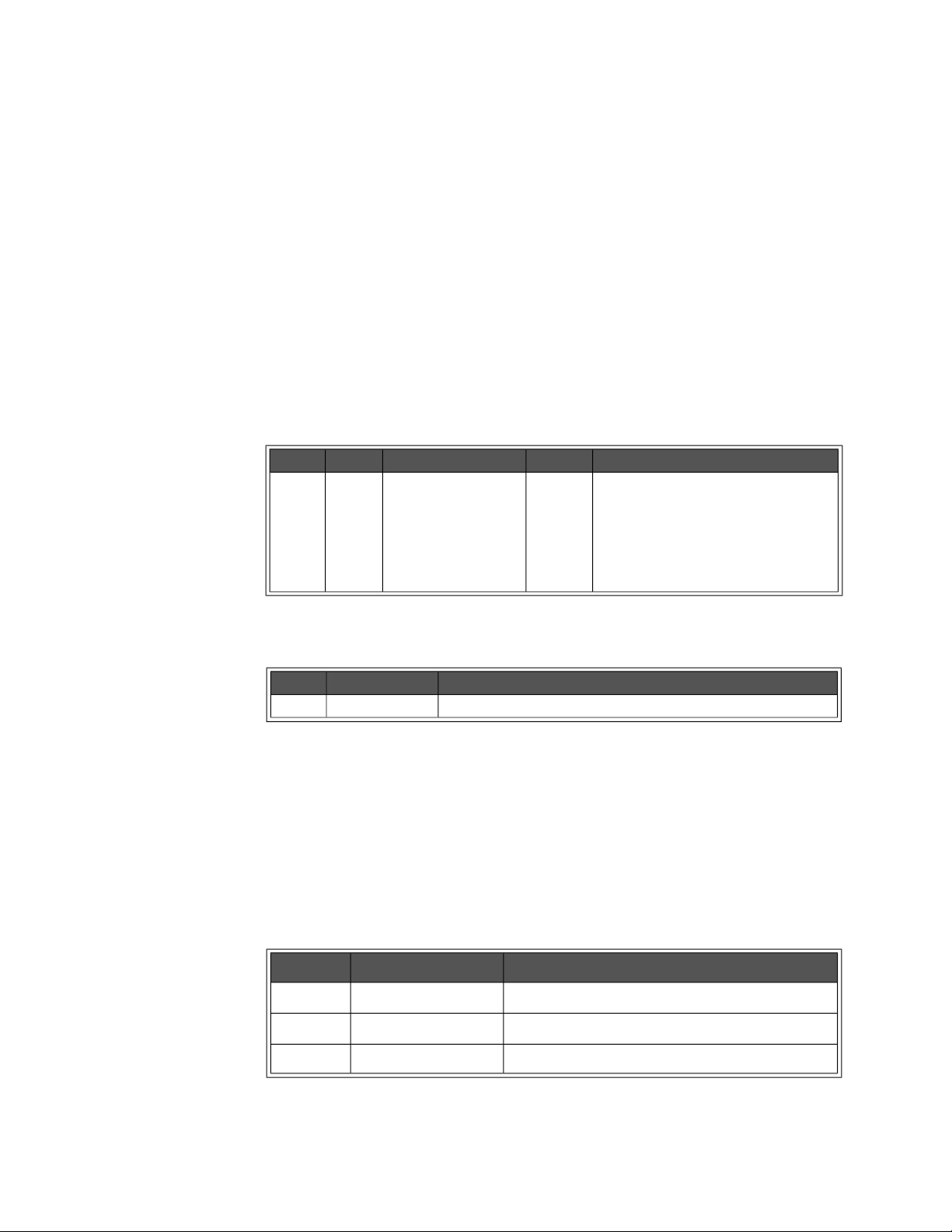
HISTory Subsystem Programming the Enhanced Monitor
HISTory:TEMPerature:MAXimum? <slot> HISTory:TEMPerature:MINimum? <slot>
HISTory:TEMPerature:MAXimum? <slot> returns a single floating point number for
the maximum temperature measured by the Enhanced Monitor for the <slot>
either manufacture of the mainframe or the most recent HIST:RES:TEMP or
since
HIST:RES:ALL.
HISTory:TEMPerature:MINimum?
<slot> returns a single floating point number for
the minimum temperature measured by the Enhanced Monitor for the <slot>
since either manufacture of the mainframe or the most recent HIST:RES:TEMP.
Parameters
Name Type Range Default Description
<slot> enum. OUT0…OUT12,
DELTa0…DELTa12,
AMBient
none Exhaust temperature for slots 0 - slot 12
Temperature change above the ambient
temperature for slots0 - slot 12
Entrance air temperature
Returned Data
Type Range Description
float minimum or maximum temperature
Comments
– The maximum/minimum temperature tracking can be zeroed by the
HISTory:RESet commands.
Error Conditions
The following table lists the most common error conditions and causes. Error
numbers and corresponding messages can be found using
query.
Number Message Probable Cause
-109 “Missing parameter” You must include the <event index> parameter.
-224 “Illegal Parameter” the <slot> parameter was not correct.
-311 “Memory error” the historical data’s memory is not available.
Keysight E8402A, E8404A C-Size Mainframes User and Service Guide 91
SYSTem:ERRor?
Page 92

Programming the Enhanced Monitor HISTory Subsystem
Reset Condition
A *RST has no effect on the HISTory subsystem.
Related Commands
HISTory:TEMPerature:[HISTogram]?, HISTory:RESet:TEMPerature,
HISTory:RESet[:ALL]
92 Keysight E8402A, E8404A C-Size Mainframes User and Service Guide
Page 93

HISTory Subsystem Programming the Enhanced Monitor
HISTory:TIME:LCALibration?
HISTory:TIME:LCALibration? returns the amount of operating time that has
passed since the last calibration was performed.
Returned Data
Type Range Default Description
<hours> uint32 0 to 4294967295 none Hours since cal
<min> uint16 0 to 60 none + minutes since cal
<sec> uint16 0 to 60 none + seconds since cal
Comments
– This query returns 4294967295,+0,+0 if a CAL, CAL:TEMP, or CAL:VOLT
has not been done. The history queue contains information on which
calibration was done.
Reset Condition
*RST has no effect on this query.
Related Commands
CAL:VOLT?, CAL:TEMP?, CAL[:ALL]?
Keysight E8402A, E8404A C-Size Mainframes User and Service Guide 93
Page 94

Programming the Enhanced Monitor HISTory Subsystem
HISTory:TIME:LHReset?
HISTory:TIME:LHReset? returns the amount of operating time since the last
HISTory:RESet (or any specific HIST:RES:xxxx) command.
Returned Data
Type Range Default Description
<hours> uint32 0 to 4294967295 none hours since history reset
<min> uint16 0 to 60 none + minutes since history reset
<sec> uint16 0 to 60 none + seconds since history reset
Comments
– If no HISTory:RESet has been performed, this query returns the amount of
time since mainframe manufacture. The history queue contains information
on which reset was done.
Error Conditions
The following table lists the most common error conditions and causes. Error
numbers and corresponding messages can be found using
SYSTem:ERRor?
query.
Number Message Probable Cause
-311 “Memory Error” Non-volatile memory is inaccessible.
Reset Condition
*RST has no effect on this query.
Related Commands
HISTory:RESet[:ALL], HISTory:RESet:TEMPerature, HISTory:RESet:QUEue
94 Keysight E8402A, E8404A C-Size Mainframes User and Service Guide
Page 95

HISTory Subsystem Programming the Enhanced Monitor
HISTory:TIME:LTST?
HISTory:TIME:LTST? returns the amount of operating time that has passed since
the last
Returned Data
Comments
*TST? or TEST command was performed.
Type Range Default Description
<hours> uint32 0 to 4294967295 none Hours since *TST
<min> uint16 0 to 60 none + minutes since *TST
<sec> uint16 0 to 60 none + seconds since *TST
– This query returns 4294967295,+0,+0 if a *TST? or TEST has not been
done. The history queue contains information on which test was done.
Reset Condition
*RST has no effect on this query.
Related Commands
*TST?, TEST[:ALL]?, TEST:BLOWer?, TEST:SENSe?, TEST:DISPlay?,
TEST:TEMPerature?, TEST:MEMory?, TEST:TIME?
Keysight E8402A, E8404A C-Size Mainframes User and Service Guide 95
Page 96
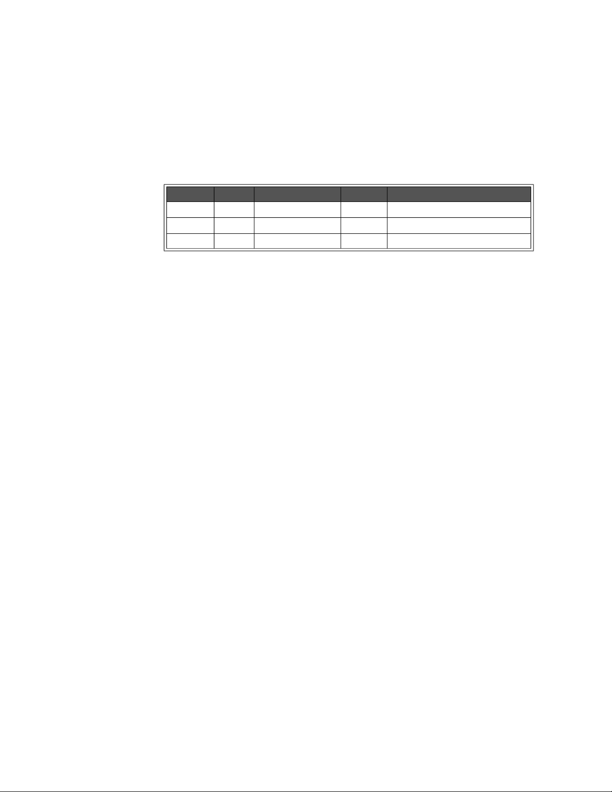
Programming the Enhanced Monitor HISTory Subsystem
HISTory:TIME:ON?
HISTory:TIME:ON? returns the amount of time operating since the last power up.
Returned Data
Type Range Default Description
<hours> uint32 0 to 4294967295 none Hours since last power-on
<min> uint16 0 to 60 none + minutes since last power-on
<sec> uint16 0 to 60 none + seconds since last power-on
Comments
– When the power is turned off and the enhanced monitor is operating on
external power, the timer does not advance.
Reset Condition
*RST has no effect on this query.
96 Keysight E8402A, E8404A C-Size Mainframes User and Service Guide
Page 97
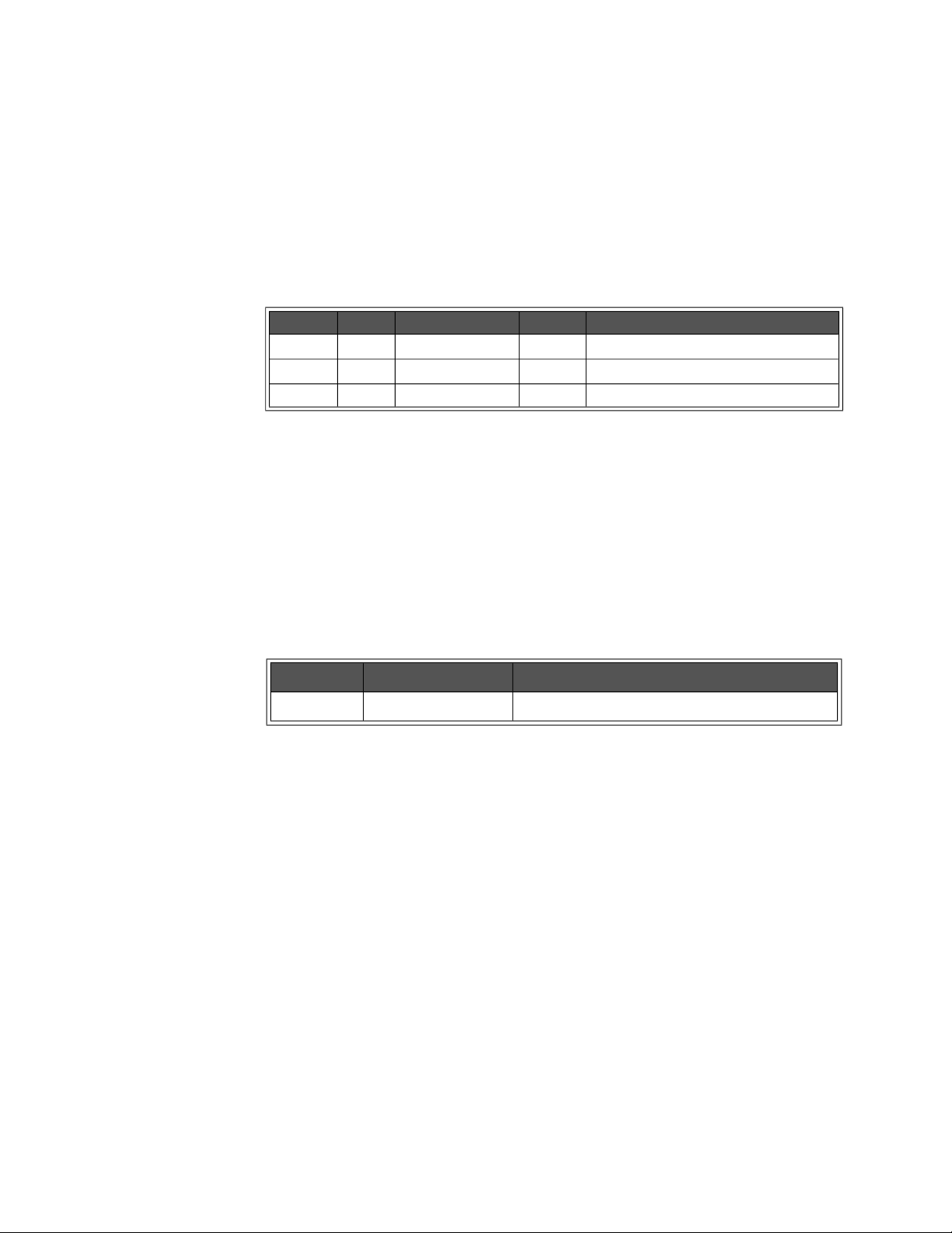
HISTory Subsystem Programming the Enhanced Monitor
HISTory:TIME:OPERating?
HISTory:TIME:OPERating? returns the amount of time the mainframe has been
operating since the last factory maintenance.
Returned Data
Type Range Default Description
<hours> uint32 0 to 4294967295 none Hours since last factory maintenance
<min> uint16 0 to 60 none + minutes since last factory maintenance
<sec> uint16 0 to 60 none + seconds since last factory maintenance
Comments
– Time stands still while the mainframe’s power supply is off. This time
returned does not indicate any time that the enhanced monitor may have
been running on external 5V.
Error Conditions
The following table lists the most common error conditions and causes. Error
numbers and corresponding messages can be found using
SYSTem:ERRor?
query.
Number Message Probable Cause
-311 “Memory Error” Non-volatile memory is inaccessible.
Reset Condition
*RST has no effect on this query.
Keysight E8402A, E8404A C-Size Mainframes User and Service Guide 97
Page 98
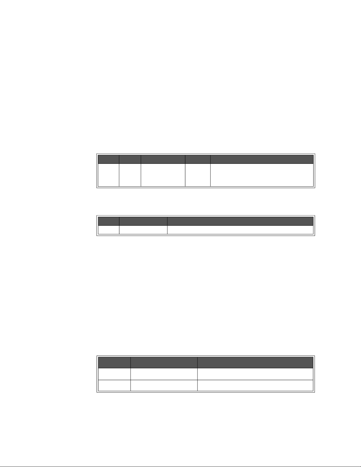
Programming the Enhanced Monitor HISTory Subsystem
HISTory:UNIT[:TIME] <unit> HISTory:UNIT[:TIME]?
HISTory:UNIT[:TIME] <unit> sets the time units that will be used to report
historical data with histograms and history events.
HISTory:UNIT[:TIME]? returns a string (enumerated) of the time units that are
used to report historical data with histograms and history events. The strings
returned are: HOUR, MIN, SEC.
Parameters
Name Type Range Default Description
<unit> enum. HOUR,
MINute,
SECond
Returned Data
HOUR Selects the time unit used within the
HISTory subsystem.
Type Range Description
enum. HOUR, MIN, SEC Time units for reporting historical data.
Comments
– Use of this command does not change the amount and resolution of the
data kept by the enhanced monitor’s HISTory subsystem. It simply
changes the reporting of that data. When set to hours it reports the data to
the nearest hour, and so on.
– The setting is stored in non-volatile memory with the
SYSTem:NVSave
command.
Error Conditions
The following table lists the most common error conditions and causes. Error
numbers and corresponding messages can be found using
query.
Number Message Probable Cause
-109 “Missing parameter” The <unit> parameter was omitted.
-224 “Illegal Parameter” The <unit> parameter was not correct.
SYSTem:ERRor?
Reset Condition
*RST sets units back to the last value saved with the SYSTem:NVSave command.
98 Keysight E8402A, E8404A C-Size Mainframes User and Service Guide
Page 99

HISTory Subsystem Programming the Enhanced Monitor
Related Commands
SYSTem:NVSave, SYSTem:NVRecall, HISTory:QUEue[:FETCh]?,
HISTory:TEMPerature[:HISTogram]?, HISTory:CURRent[:HISTogram]?
Keysight E8402A, E8404A C-Size Mainframes User and Service Guide 99
Page 100
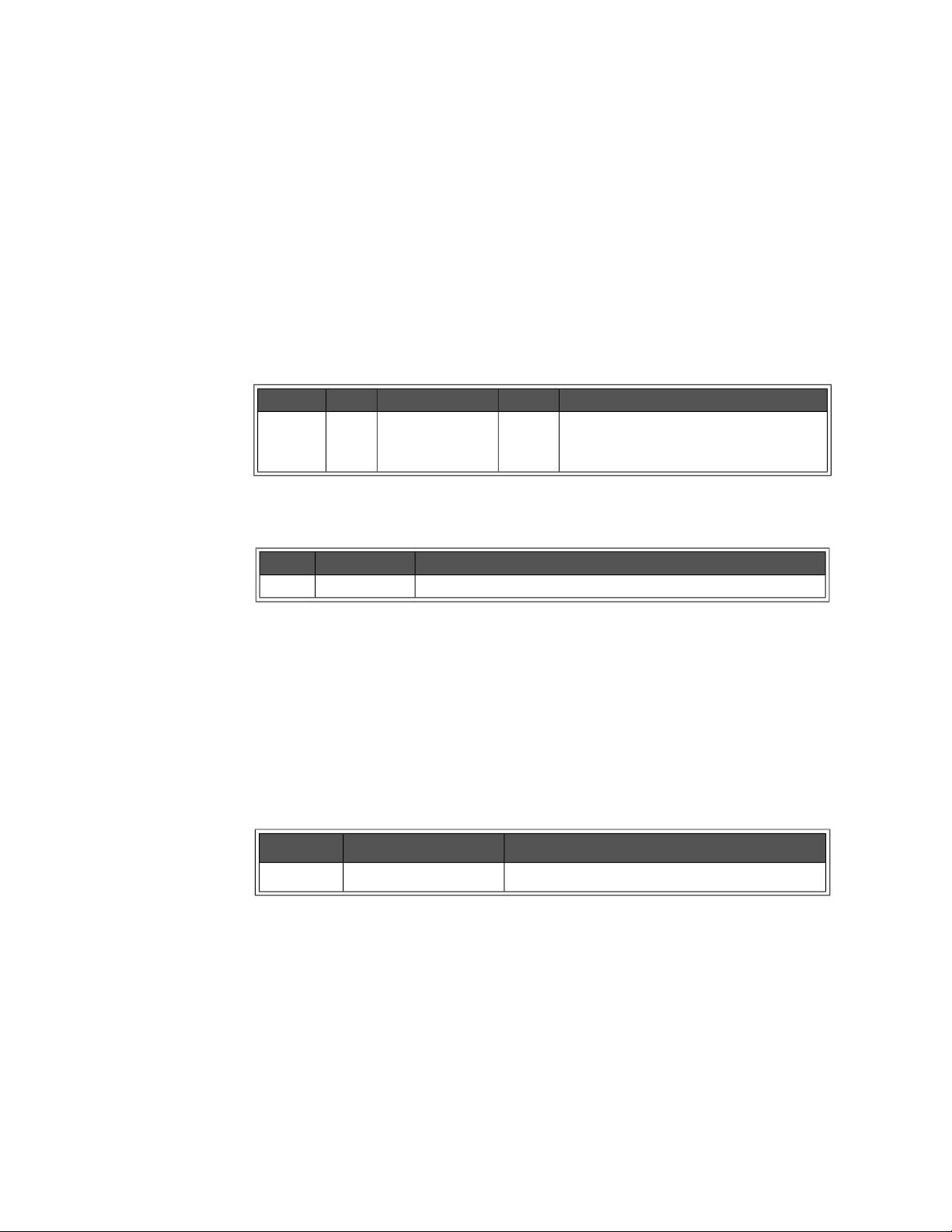
Programming the Enhanced Monitor HISTory Subsystem
HISTory:VOLTage:CMAXimum? <supply> HISTory:VOLTage:CMINimum? <supply>
HISTory:VOLTage:CMAXimum? <supply> returns the maximum voltage measured
by the Enhanced Monitor for the <supply> since power-on of the mainframe.
HISTory:VOLTage:CMINimum? <supply> returns the minimum voltage measured
by the Enhanced Monitor for the <supply> since power-on of the mainframe.
Parameters
Name Type Range Default Description
<supply> enum. P5,P12,N12,P24,
N24,N5PT2,N2,
P5STby
Returned Data
none Selects the power supply for the current
maximum request. P5 is positive 5 Vdc
supply, N12 is negative 12 Vdc supply, etc.
Type Range Description
float. Minimum or maximum voltage.
Comments
– These maximums and minimums can be reset by powering the mainframe
off and then powering it back on.
Error Conditions
The following table lists the most common error conditions and causes. Error
numbers and corresponding messages can be found using
SYSTem:ERRor?
query.
Number Message Probable Cause
-224 “Illegal Parameter” The <supply> parameter was not correct.
Reset Condition
A *RST has no effect on the HISTory subsystem.
Related Commands
HISTory:VOLTage:MAXimum?, HISTory:VOLTage:MINimum?,
HISTory:VOLTage:[HISTogram]?
100 Keysight E8402A, E8404A C-Size Mainframes User and Service Guide
 Loading...