

Page 1

Keysight Wireless Test Platform
E7515B UXM 5G Wireless Test Platform
Getting Started
Guide
Page 2

Notices
© Keysight Technologies, Inc.
2014-2019
No part of this manual may be
reproduced in any form or by any
means (including electronic storage
and retrieval or translation into a
foreign language) without prior
agreement and written consent from
Keysight Technologies, Inc. as
governed by United States and
international copyright laws.
Trademark Acknowledgments
Manual Part Number
E7515-90024
Edition
Edition 1, August 2019
Supersedes: July 2018
Printed in USA/Malaysia
Published by:
Keysight Technologies
1400 Fountaingrove Parkway
Santa Rosa, CA 95403
Warranty
THE MATERIAL CONTAINED IN THIS
DOCUMENT IS PROVIDED “AS IS,”
AND IS SUBJECT TO BEING
CHANGED, WITHOUT NOTICE, IN
FUTURE EDITIONS. FURTHER, TO
THE MAXIMUM EXTENT PERMITTED
BY APPLICABLE LAW, KEYSIGHT
DISCLAIMS ALL WARRANTIES,
EITHER EXPRESS OR IMPLIED WITH
REGARD TO THIS MANUAL AND
ANY INFORMATION CONTAINED
HEREIN, INCLUDING BUT NOT
LIMITED TO THE IMPLIED
WARRANTIES OF
MERCHANTABILITY AND FITNESS
FOR A PARTICULAR PURPOSE.
KEYSIGHT SHALL NOT BE LIABLE
FOR ERRORS OR FOR INCIDENTAL
OR CONSEQUENTIAL DAMAGES IN
CONNECTION WITH THE
FURNISHING, USE, OR
PERFORMANCE OF THIS
DOCUMENT OR ANY INFORMATION
CONTAINED HEREIN. SHOULD
KEYSIGHT AND THE USER HAVE A
SEPARATE WRITTEN AGREEMENT
WITH WARRANTY TERMS
COVERING THE MATERIAL IN THIS
DOCUMENT THAT CONFLICT WITH
THESE TERMS, THE WARRANTY
TERMS IN THE SEPARATE
AGREEMENT WILL CONTROL.
Technology Licenses
The hardware and/or software
described in this document are
furnished under a license and may be
used or copied only in accordance
with the terms of such license.
U.S. Government Rights
The Software is “commercial
computer software,” as defined
by Federal Acquisition Regulation
(“FAR”) 2.101. Pursuant to FAR
12.212 and 27.405-3 and
Department of Defense FAR
Supplement (“DFARS”) 227.7202,
the U.S. government acquires
commercial computer software
under the same terms by which
the software is customarily
provided to the public.
Accordingly, Keysight provides
the Software to U.S. government
customers under its standard
commercial license, which is
embodied in its End User License
Agreement (EULA), a copy of
which can be found at
http://www.keysight.com/find/sweula
The license set forth in the EULA
represents the exclusive authority
by which the U.S. government
may use, modify, distribute, or
disclose the Software. The EULA
and the license set forth therein,
does not require or permit,
among other things, that
Keysight: (1) Furnish technical
information related to
commercial computer software
or commercial computer
software documentation that is
not customarily provided to the
public; or (2) Relinquish to, or
otherwise provide, the
government rights in excess of
these rights customarily provided
to the public to use, modify,
reproduce, release, perform,
display, or disclose commercial
computer software or
commercial computer software
documentation. No additional
government requirements
beyond those set forth in the
EULA shall apply, except to the
extent that those terms, rights, or
licenses are explicitly required
from all providers of commercial
computer software pursuant to
the FAR and the DFARS and are
set forth specifically in writing
elsewhere in the EULA. Keysight
shall be under no obligation to
update, revise or otherwise
modify the Software. With
respect to any technical data as
defined by FAR 2.101, pursuant
to FAR 12.211 and 27.404.2 and
DFARS 227.7102, the U.S.
government acquires no greater
than Limited Rights as defined in
FAR 27.401 or DFAR 227.7103-5
(c), as applicable in any technical
data.
Safety Notices
A CAUTION notice denotes a hazard. It
calls attention to an operating
procedure, practice, or the like that,
if not correctly performed or adhered
to, could result in damage to the
product or loss of important data. Do
not proceed beyond a CAUTION
notice until the indicated conditions
are fully understood and met.
A WARNING notice denotes a hazard.
It calls attention to an operating
procedure, practice, or the like that,
if not correctly performed or adhered
to, could result in personal injury or
death. Do not proceed beyond a
WARNING notice until the indicated
conditions are fully understood and
met.
Page 3

Where to Find the Latest Information
Documentation is updated periodically. For the latest information about these products, including instrument software
upgrades, application information, and product information, browse to one of the following URLs, according to the name
of your product:
http://www.keysight.com/find/e7515B
To receive the latest updates by email, subscribe to Keysight Email Updates at the following URL:
http://www.keysight.com/find/MyKeysight
Information on preventing instrument damage can be found at:
www.keysight.com/find/PreventingInstrumentRepair
Is your product software up-to-date?
Periodically, Keysight releases software updates to fix known defects and incorporate product enhancements. To search
for software updates for your product, go to the Keysight Technical Support website at:
http://www.keysight.com/find/techsupport
3
Page 4

4
Page 5

Table of Contents
Introduction 9
Overview 10
Purpose and Function 10
Differences between E7515B and E7515E 11
Millimeter-Wave Accessory Instruments 16
Reference Documents 18
Instrument Information and Maintenance 19
Size and Weight 19
Power Requirements 19
Electrical Safety 19
Environmental Conditions 21
EMI and EMC Compliance 21
Ventilation 21
Instrument Maintenance 22
Protecting against electrostatic discharge 22
UXM 5G Software Applications 24
Licenses 24
About the Test Applications 25
Installing the Test Applications 25
Contents
Quick Start 27
Initial Inspection 28
Shipping Problems? 29
Instrument Location and Rack Mounting Requirements 30
Locating the Test Platform 30
Table Top Ambient Temperature 30
Rack Mounting: Hardware and Temperature 30
Turning On the Test Platform the First Time 32
Shutting Down the Test Platform 37
Licensing 38
Transportable Licenses 39
LAN Connectivity 40
Corporate Domains 40
Windows Updates 41
Anti-virus Protection and Firewalls 43
Control Panel Functions 45
Getting Started Guide 5
Page 6

Contents
The Control Panel 46
Viewing the Control Panel 46
Control Panel Icons 47
HCCU Functions 49
Hardware Configuration Control Utility (HCCU) 50
Viewing the HCCU 51
HCCU Tabs 52
System Tab 53
Change Setup 56
Scenario Tab 60
Information Tab 61
Calibration Tab 62
Tools Tab 63
HCCU Configuration Icon (gear symbol) 66
Help ("?" Icon) 66
UXM Arrays 67
Front and Rear Panel Functions 71
Front Panel Features 72
Power Status Indicator 74
Rear Panel Features 75
VDTAMC Cards 76
CCTAMC Card 77
FPGA Expansion Module (E7515B-FP1) 78
AUXM Connectors 79
ICM Connectors 80
DCB+ Connectors 81
PCM 82
RFIO 83
AC Power 83
Front and Rear Panel Symbols 84
Test Platform Operating System 87
Keysight Software Installed 88
Customer Installation of Software 88
User Accounts 89
Administrator Account 89
Changing Account Passwords 90
System Maintenance 93
6 Getting Started Guide
Page 7

Back-up 93
System Restore 93
Hard Drive Partitioning and Use 94
Disk Drive Recovery Process 95
Updating the Keysight E7515B UXM 5G software 99
Using the E7515B/E7515B UXM 5G Firmware Update Tool 99
Updating the Keysight 5G NR Test Application 101
Updating the Application 101
Troubleshooting 105
Identifying Problems 106
Returning Your Test Set for Service 107
Calling Keysight Technologies 107
Locations for Keysight Technologies 108
Contents
Getting Started Guide 7
Page 8

Contents
8 Getting Started Guide
Page 9

Keysight Wireless Test Set
E7515B UXM 5G Wireless Test Platform
Getting Started Guide
1 Introduction
The following topics can be found in this section:
“Overview” on page 10
“Instrument Information and Maintenance” on page 19
“UXM 5G Software Applications” on page 24
9
Page 10

Introduction
Overview
Overview
The purpose of this guide is to provide you with the basic steps for getting
started with the Keysight E7515B UXM 5G Wireless Test Platform, and to tell
you where you can go to get additional information. It also provides first-time
power on instructions, licensing information, operating system information,
and general hardware information.
Figure 1-1 Keysight E7515B UXM 5G Wireless Test Platform
Purpose and Function
The E7515B UXM 5G wireless test platform provides the signaling and
measurement core for Keysight’s 5G network emulation solution portfolio.
10 Getting Started Guide
Page 11

Introduction
Overview
Differences between E7515B and E7515E
The E7515B model of the UXM 5G differs from the economy version (E7515E)
in that it includes circuit boards which the economy version omits., and it omits
some internal circuit boards. Consequently, it has some limitations on
functionality, and particularly on RF port usage, which are explained here for
the benefit of users who may be familiar with the UXM 5G in its E7515B
version.
The eight Tx/Rx ports on the front panel (RF 1-8) communicate with the
instrument’s interior source and analyzer by way of the RFIO board. Although
the RFIO board is the essentially the same as the E7515E version, it must
interface with the Mixed Signal and Radio Frequency boards, which in the case
are different. The E7515B contains two Mixed Signal Boards (MSB 1 and MSB
2) rather than one, and also two Radio Frequency Boards (RFB 1 and RFB 2)
rather than one. This expands the capacity of the RFIO board to exchange
signals with the source and analyzer.
Figure 1-2 MSB 1/2 and RFB 1/2 interfacing to RFIO board
Getting Started Guide 11
Page 12

Introduction
Overview
Figure 1-3 Overall block diagram of the RFIO board
The diagram above shows signal routing through the RFIO board (it is
simplified, omitting certain paths used for reference or calibration signals).
In the E7515E, a maximum of eight RF ports can be used at a time. All eight
can be transmit ports, provided no ports are being used as receive ports. A
maximum of four ports at a time can be used as receive ports.
12 Getting Started Guide
Page 13

Introduction
Overview
The diagram below shows how transmit signals are routed to the front panel
RF ports. In this example, ports RF 1, RF 2, and RF 3 are used.
Figure 1-4 Tx paths to the front panel RF ports
Getting Started Guide 13
Page 14

Introduction
Overview
The diagram below shows how receive signals are routed from the front panel
RF ports. The signal routing is more complex than in the case of transmit
signals. The receive path from either of two RF ports (RF 2 or RF 6, in this
example) must go through the switch highlighted in yellow. The receive signal
furnished to the Rx combination block must come from port RF 2 or port RF 6,
but not both at once. That is why there cannot be more than four receive ports
used at once.
Figure 1-5 Rx path from the front panel RF ports
The remaining RF ports follow a similar pattern. The remaining receive paths to
the Rx combination block can come from RF 1 or 5 (not both), RF 3 or 7 (not
both), and RF4 or 8 (not both).
14 Getting Started Guide
Page 15

Introduction
Overview
The RF paths involved in a simple port setup (output on RF 1/2/3, input on RF
6) are illustrated in Figure 1-6.
Figure 1-6 RF path example: RF 1 (Tx), RF 2 (Tx), RF 3 (Tx) and RF 6 (Rx)
Getting Started Guide 15
Page 16

Introduction
Overview
Millimeter-Wave Accessory Instruments
For testing at higher frequencies than the UXM itself can generate, two other
instruments are commonly used with the UXM: the M1740A mmWave
Transceiver (usually called the Remote Radio Head or RRH) and the E7770A
Common Interface Unit (usually called the CIU).
Figure 1-7 UXM used with M1740A (bottom) and E7770A (top)
16 Getting Started Guide
Page 17

Introduction
Overview
As illustrated below, the CIU is able to upconvert the RF output of the UXM to
the 6-12 GHz range (the lower portion of the picture), and apply this signal to
the DUT. On the same path, it also can accept a return signal from the DUT,
downconvert it to the range of the UXM, and return it to an input port on the
UXM.
For mmWave testing (the upper portion of the picture), the RF output of the
UXM can pass through the CIU (bypassing the upconverter) to the M1740A
remote radio head, where it is upconverted to a mmWave signal which is
transmitted wirelessly to the DUT. The returned mmWave signal is received by
the M1740A, downconverted, and passed back through the CIU to the UXM RF
input. The CIU also supplies the combined LO, DC Power, and Control inputs
which the M1740A requires. The LO/Ctrl/Pwr output of the CIU is the only
essential connection between the CIU and M1740A, because the RF input and
output from the UXM can be cabled directly between the UXM and the
M1740A, rather than passing through the CIU as in this illustration.
Figure 1-8 Functional block diagrams of M1740A and E7770A
Getting Started Guide 17
Page 18

Introduction
Overview
Reference Documents
More detailed information about the test platform is available on the Document
Library tab of this web page:
http://www.keysight.com/find/E7515B
Product documents included there include:
— E7515B UXM 5G Wireless Test Platform - User's and Programmer's Guide
— E7515B UXM 5G Wireless Test Platform - Configuration Guide
— 5G NR Online documentation (help files) for the UXM 5G Test Applications.
18 Getting Started Guide
Page 19

Introduction
Instrument Information and Maintenance
Instrument Information and Maintenance
Size and Weight
The weight and dimensions of the E7515B are as follows:
— Weight: 42.2 kg (with 2 cells)
— Height: 309 mm (323 mm with feet)
— Width: 436 mm (452.5 with lateral handles)
— Depth 554 mm
Power Requirements
Voltage & frequency: 100-240V~, 50-60 Hz, nominal
Power consumption: 1400 W Max
Mains supply voltage fluctuates up to +/- 10% of the nominal voltage.
Transient over-voltages are typically present on the mains supply.
Electrical Safety
This is a Safety Class 1 Product (provided with a protective earth ground
incorporated in the power cord). The mains plug shall only be inserted in a
socket outlet provided with a protective earth contact. Any interruption of the
protective conductor inside or outside of the instrument is likely to make the
instrument dangerous. Intentional interruption is prohibited (IEC 61010-1).
If this product is not used as specified, the protection provided by the equipment
could be impaired. This product must be used in a normal condition (in which all
means for protection are intact) only. Install the instrument so that the
detachable power cord is readily identifiable and easily reached by the operator.
The detachable power cord is the instrument disconnecting device. It
disconnects the mains circuits from the mains supply before other parts of the
instrument. The front panel switch is only a standby switch and is not a LINE
switch. Alternatively, an externally installed switch or circuit breaker (which is
readily identifiable and is easily reached by the operator) may be used as a
disconnecting device.
Getting Started Guide 19
Page 20

Introduction
Instrument Information and Maintenance
This instrument has an auto-ranging line voltage input. Ensure the supply
voltage is within the specified range and the rating for the service breaker is
correct.
When installing the product in a cabinet the convection into and out of the
product must not be restricted. The ambient temperature (outside the cabinet)
must be less than the maximum operating temperature of the product by 4
for every 100 watts dissipated in the cabinet. If the total power dissipated in
the cabinet is greater than 800 watts, then forced convection must be used. It
is your responsibility to ensure the ambient temperature does not exceed the
rated ambient temperature stated in the specification.
The Mains wiring and connectors shall be compatible with the connector used
in the premise electrical system. Failure, to ensure adequate earth grounding
by not using the correct components may cause product damage, and serious
injury.
Use the Keysight supplied power cord or one with the same or better electrical
rating.
° C
20 Getting Started Guide
Page 21

Introduction
Instrument Information and Maintenance
Environmental Conditions
This product is designed for use in Installation Category II and Pollution Degree
2 environment.
This product is designed for use in the following conditions:
— For indoor use only
— Operating Temperature 10° C to 40° C, 5% to 85% (non-condensing)
relative humidity
— Storage Temperature -40° C to +70° C, 5% to 85% (non-condensing relative
humidity)
— Altitude up to 2000 meters
— OVERVOLTAGE CATEGORY II and Pollution degree 2
EMI and EMC Compliance
Complies with European EMC Directive 2004/108EC
— ICES/NMB-001
— South Korean Class A EMC declaration: This equipment is Class A suitable
Ventilation
This ISM device complies with Canadian ICES-001
Cet appareil ISM est conforme a la norme NMB-001 du Canada.
for professional use and is for use in electromagnetic environments outside
of the home.
A 급 기기 ( 업무용 방송통신기 자재 )
이기기는 업무용 (A 급 ) 전자파 적합기기로서 판매자 또는 사용자는 이 점을 주의
하시기 바라며 ,
가정외의 지역에서 사용하는 것을 목적으로 합니다
When installing the product in a cabinet the convection into and out of the
product must not be restricted. The ambient temperature (outside the cabinet)
must be less than the maximum operating temperature of the product by 4
for every 100 watts dissipated in the cabinet. If the total power dissipated in
the cabinet is greater than 800 watts, then forced convection must be used. It
is your responsibility to ensure the ambient temperature does not exceed the
rated ambient temperature stated in the specification.
° C
Getting Started Guide 21
Page 22

Introduction
Instrument Information and Maintenance
Instrument Maintenance
Protecting Against Overpowering
The input circuitry of the test platform can be damaged by applying signals
that exceed the maximum safe input level of +27 dBm average total power or
+/- 30 VDC. Repairing damage to the input circuitry can be expensive. If the
test platform will be used to measure signals which might be near the
maximum safe input level, use external attenuators and/or limiters to help
protect the test platform input. Always use the three-prong AC power cord
supplied with this product. Failure to ensure adequate earth grounding by not
using this cord can cause product damage.
Cleaning the Instrument
To prevent electrical shock, disconnect the Keysight Technologies Model
E7515B from mains before cleaning. Use a dry cloth or one slightly dampened
with water to clean the external case parts. Do not attempt to clean internally.
Cleaning the Connectors
Cleaning connectors with alcohol shall only be done with the instrument power
cord removed, and in a well-ventilated area. Allow all residual alcohol moisture
to evaporate, and the fumes to dissipate prior to energizing the instrument.
Keep isopropyl alcohol away from heat, sparks, and flame. Store in a tightly
closed container. It is extremely flammable. In case of fire, use alcohol foam, dry
chemical, or carbon dioxide; water may be ineffective.
Use isopropyl alcohol with adequate ventilation and avoid contact with eyes,
skin, and clothing. It causes skin irritation, may cause eye damage, and is
harmful if swallowed or inhaled. It may be harmful if absorbed through the skin.
Wash thoroughly after handling. In case of spill, soak up with sand or earth.
Flush spill area with water. Dispose of isopropyl alcohol in accordance with all
applicable federal, state, and local environmental regulations.
Protecting against electrostatic discharge
Electrostatic discharge (ESD) can damage or destroy electronic components
(the possibility of unseen damage caused by ESD is present whenever
components are transported, stored, or used).
Test equipment and ESD
— Before connecting any coaxial cable to a test platform connector for the
first time each day, momentarily short the center and outer conductors of
the cable together.
— Personnel should be grounded with a 1
MΩ resistor-isolated wrist-strap
before touching the center pin of any connector and before removing any
assembly from the test platform.
22 Getting Started Guide
Page 23

Introduction
Instrument Information and Maintenance
— Be sure that all instruments are properly earth-grounded to prevent
build-up of static charge.
Additional information about ESD
For more information about ESD and how to prevent ESD damage, contact the
Electrostatic Discharge Association:
http://www.www.esda.org
The ESD standards developed by this agency are sanctioned by the American
National Standards Institute (ANSI).
Getting Started Guide 23
Page 24

Introduction
UXM 5G Software Applications
UXM 5G Software Applications
The UXM 5G operates within the C8700200A 5G Test Application Framework.
Different capabilities of this framework are licensed separately, as listed below:
You must purchase a Test Application license to use its features in the UXM 5G.
Licenses
The license numbers given here are simplified; the actual numbers would
include a suffix to specify the license type (for example, the suffix -1TP would
designate that the license is transportable and perpetual).
Number Description
C8700100A 5G Interactive Script Environment
C8700101A 5G Interactive Live
C8700200A Test Application Framework
C8700300A Host interface
C8701000A Protocol R+D Tools
C8701400A PRT Pre-5G TC-00: PROT interoperability test cases for 5GTF
C870240AA RFT Pre-5G T-0A: Measurement tools for 5GTF
C87024AAA RFT Pre-5G TC-AA: RF interoperability test cases for 5GTF
C87024ABA RFT Pre-5G TC-AB: RF Tx and Rx test cases for 5GTF
C870250AA RFT 5G NR T-0A: Measurement tools
C8703N0AA KPI T-0A: Data Server tools
C87300P1A LTE IP data
C87300R1A LTE UL RF measurements
C8730115A LTE Rel 15 – core signaling
C8730215A LTE Rel 15 – advanced signaling
C8732114A C-V2X Rel 14 – PC5 Signaling
C87340P1A Pre-5G IP data for 5GTF
C87340R1A Pre-5G UL RF measurements for 5GTF
C8734100A Pre-5G - core signaling for 5GTF
C8734200A Pre-5G - advanced signaling for 5GTF
C87350P1A 5G NR IP data
24 Getting Started Guide
Page 25

Introduction
UXM 5G Software Applications
About the Test Applications
The applications run on the embedded Windows controller present in the UXM
5G and use the provided touch-screen based interface, integrated fading,
network emulation and measurement capabilities present in the test platform
to provide you with a simple to use, bench-top design verification tool.
Installing the Test Applications
This software comes already installed on your UXM 5G. If there is a problem
and you need to re-install it, refer to Installing the Software on “Updating the
Keysight E7515B UXM 5G software” on page 99.
Getting Started Guide 25
Page 26

Introduction
UXM 5G Software Applications
26 Getting Started Guide
Page 27

Keysight Wireless Test Set
E7515B UXM 5G Wireless Test Set Platform
Getting Started Guide
2 Quick Start
This section describes how to set up your UXM 5G, install product licenses,
and provide test platform maintenance. You can also contact your Keysight
representative to obtain on-site start-up assistance to help you with all steps
outlined in this section, which is included with your UXM 5G purchase.
The following topics can be found in this section:
“Initial Inspection” on page 28
“Turning On the Test Platform the First Time” on page 32
“Licensing” on page 38
LAN Connectivity on page 40
Anti-virus Protection and Firewalls on page 43
27
Page 28

Quick Start
Initial Inspection
Initial Inspection
Inspect the shipping container and the cushioning material for signs of stress.
Retain undamaged shipping materials for future use, as you may wish to ship
the test platform to another location or to Keysight Technologies for service.
Verify the contents of the container against the table below.
This instrument is heavy. Two people are required to lift this instrument.
Please consult ergonomic guidelines regarding placement of the external
keyboard when using it with the instrument. Using the keyboard in an
uncomfortable or awkward environment could result in personal injury.
Item Deliverable Description
Getting Started Guide (this
document)
Keysight E7515B UXM 5G
Wireless Test Platform
License entitlement
certificate(s)
Provides first-time power on
instructions, licensing
information, operating system
information, and general
hard ware information.
You must register your instrument
purchase using the included
entitlement certificate.
Follow the instructions on the
Certificate. If this is your first visit
to the license management
website, you will be required to
register.
Refer to
page 38
“Licensing” on
for more information.
28 Getting Started Guide
Page 29

Quick Start
Initial Inspection
Item Deliverable Description
Keysight Test USIM card,
tri nano (E7515-10910)
Test USIM card, tri nano IM
card (T1099-10001)
Power Cable Connection for Instrument Power
See
www.keysight.com/find/usim
for details.
Shipping Problems?
If the shipping materials are damaged or the contents of the container are
incomplete:
— Contact the nearest Keysight Technologies office.
— Keep the shipping materials for the carrier’s inspection.
— If you must return a test platform to Keysight Technologies, use the
undamaged original or comparable shipping materials. See “Returning Your
Test Set for Service” on page 107.
Getting Started Guide 29
Page 30
Quick Start
Instrument Location and Rack Mounting Requirements
Instrument Location and Rack Mounting Requirements
Locating the Test Platform
Make sure that the left-side panel fan inlet and right-side panel exhaust vent
areas are not obstructed. The minimal required clearance is 2.75 inches (7 cm).
Install the instrument so that the detachable power cord is readily identifiable
and is easily reached by the operator. The detachable power cord is the
instrument disconnecting device. It disconnects the mains circuits from the
mains supply before other parts of the instrument. The front-panel switch is only
a standby switch and does not act as a LINE switch. The rear-panel switch is a
LINE switch, however it is only to be relied upon as supplementary protection. If
needed, an externally installed switch or circuit breaker (which is readily
identifiable and is easily reached by the operator) may be used as a
disconnecting device.
Table Top Ambient Temperature
Do not exceed an ambient temperature of 45? C when operating the instrument
on a table top.
Rack Mounting: Hardware and Temperature
If you choose to locate your test platform in a rack, follow the guidelines
provided in this section.
Based on the type of equipment rack you have, you must determine what rack
rails you need. If you are using a Keysight System Test Rack, you can find
information on what to order by referring to the Rack Mounting Flange Kit
(Option E7515B-1CM) Installation Note.
When mounting instrument in a rack, do not exceed the level of:
—Outside rack ambient temperature of 35°C, or
—Internal rack air temperature of 45°C
Do not rack mount the test platform side-by-side with any other instrument
with side ventilation. Make sure the exhaust air from the first instrument is
directed away from the inlet of the second unit. If the pre-heated air from the
first instrument is directed into the second instrument, it can cause excessive
operating temperatures in the second unit and can cause instrument failures.
The test platform draws air in from the left side and exhausts air from the right
side. Do not mount other equipment immediately above the instrument. The
minimal required clearance is 2.75 inches (7 cm).
30 Getting Started Guide
Page 31

Quick Start
Instrument Location and Rack Mounting Requirements
VENTILATION REQUIREMENTS: When installing the instrument(s) into a
cabinet consideration shall be given to the convection flow into and out of the
cabinet. Consideration shall also be given to the individual instruments to avoid
having the heated discharge of one instrument, now becoming the cooling
intake air for another instrument.
Another area of concern is verification that the maximum ambient operating
temperature of the instrument(s) is not exceeded by cabinet installation.
Keysight recommends forced air convection whenever instruments are
installed in a cabinet and further recommends that the maximum operating
temperature of the cabinet be reduced 10°C from the lowest maximum
operating temperature of a single instrument.
If there are any concerns or special requirements a Keysight Field Engineer
should be consulted to assure instrument(s) temperature compliance and
performance.
Getting Started Guide 31
Page 32

Quick Start
Turning On the Test Platform the First Time
Turning On the Test Platform the First Time
DO NOT remove the AC power during boot-up/shutdown of the operating
system or during the process of initializing the software. This can cause
damage to the system files and prevent proper operation of the instrument.
Before switching on this instrument, make sure the supply voltage is in the
specified range.
Step Action Notes
1. Connect power
cable
2. Connect the
mouse and the
keyboard
(Optional).
3. Power on the test
platform
Install the instrument so that the
detachable power cord is easily
reached by the operator.
Connect the mouse and the keyboard
to the test platform’s USB ports.
Position the test platform so you have
easy access to the power cord and plug
it in.
Select the On position for the
rear-panel AC line power switch.
Press the power button (bottom right of
instrument front panel) when the LED
above the power button illuminates in
yellow. (It is best to wait at least 3
seconds after the LED is yellow before
pressing the power button.)
Ensure power outlet is provided with a protective
ground as specified.
See
“Instrument Location and Rack
Mounting Requirements” on page 30
and
“Power Requirements” on page 19.
Front-panel power button:
32 Getting Started Guide
Page 33

Quick Start
Turning On the Test Platform the First Time
Step Action Notes
4. You will be
prompted to
accept the End
User License
Agreement
(EULA).
Select the
that you accept the license agreement.
Agree button to indicate
After you agree to the EULA, the operating system
boots-up and you see a black background with
Keysight Technologies logo displayed on the
screen. The E7515B Control Panel (shown below)
is overlaid on top of this Keysight screen and
remains visible while the internal hardware boards
of the UXM 5G are booted-up.
Getting Started Guide 33
Page 34

Quick Start
Turning On the Test Platform the First Time
Step Action Notes
5. Wait until you see
the green or red
color displayed in
the UXM 5G
pictorial graphic,
located in the
upper left corner
of the E7515B
Control Panel.
The changing colors of the E7515B
Control Panel pictorial graphic indicate
the “ready-state” of the UXM 5G.
Yellow indicates the UXM 5G is in the process of
becoming ready for operation.
Green indicates the UXM 5G is ready for operation.
Red indicates an error has occurred in the system
and the unit is not ready for operation. (This
requires troubleshooting, as the problem is not
expected to resolve on its own.)
6. Make sure all
required Windows
updates are made.
7. Run the HCCU. Activate the Keysight NES Hardware Configuration
8. If necessary,
install the Google
Chrome browser.
Windows must be configured properly
on your instrument to ensure this.
The broswer can be downloaded from:
Windows updates are necessary to protect your
E7515B instrument against the latest malware and
viruses. See
page 41
Control Utility by double-clicking the Keysight
HCCU icon on the desktop. (This utility runs within
a browser window.)
Microsoft Internet Explorer is not recommended
as the browser for this utility, because of known
compatibility issues. The recommended browser is
Google Chrome.
“Windows Updates” on
.
https://www.google.com/chrome/browser/
After installation, set up Chrome as the default browswer (Google provides setup instructions
for this).
34 Getting Started Guide
Page 35

Quick Start
Turning On the Test Platform the First Time
Step Action Notes
9. Select a scenario. In the HCCU, on the Scenarios tab,
select a testing scenario (such as
NR5GFormatOpt03_RF) and click the
Activate icon. Wait while the selection
is set up (an "in progress" message is
displayed while the scenario is being
activated).
10. Run the test
application.
11. Run the HCCU. Activate the Keysight NES Hardware
12. Wait for the
application to
load.
Activate the test application by
double-clicking on the 5G NR Test App
icon on the desktop. (There is a lengthy
delay while the software loads.)
Configuration Control Utility by
double-clicking the Keysight HCCU
icon on the desktop. (This utility runs
within a browser window.)
Later in the loading process, a
splash-screen is displayed (with a
progress indicator).
Getting Started Guide 35
Page 36

Quick Start
Turning On the Test Platform the First Time
Step Action Notes
13. Begin using your
new software after
the splash screen
disappears.
For detailed information on how to use
the software, refer to the 5G NR Test
Application Help.
36 Getting Started Guide
Page 37

Quick Start
Turning On the Test Platform the First Time
Shutting Down the Test Platform
Step Action Notes
1. Close the test
application by
clicking on the "X"
button at the upper
right.
2. It is recommended
that you press the
front-panel power
button, or select
Shutdown from the
MS Windows Start
menu, or select the
Shutdown icon on
the E7515B Control
Panel (as illustrated
here).
To force power off:
press and hold the
front-panel power button for
more than 5 seconds.
The display will show the windows
shut-down screen.
Do not force power off in this way unless the normal
procedure fails (a forced shutdown carries a risk of
corrupting hard-drive data). If the last power
shutdown was done in that way, the message shown
below will be displayed on power-up as a reminder.
Getting Started Guide 37
Page 38

Licensing
Quick Start
Licensing
All licenses required to operate your UXM 5G have been installed at the factory
(except transportable licenses – see below) and can be recovered using one of
the procedures outlined in Chapter 6, “Test Platform Operating System”, on
page 87. Complete these steps if you need to add licensing to your UXM 5G:
1. Follow the directions located on the license entitlement certificate that
you received with the delivery of your UXM 5G.
You may register or sign in with your profile at:
www.keysight.com/find/softwaremanager
in order to obtain any software updates and/or new licenses using your
entitlement details.
2. In order to redeem a license unique to your UXM 5G, you will need to enter
the “Host ID”. To determine the Host ID of your UXM 5G, select the License
Manager icon located on the E7515B Control Panel (see “Control Panel
Icons” on page 47.) The Keysight License Manager (KLM) window opens
and displays your Host ID:
3. After the registration/sign-in/filling in information, an e-mail with the
generated license file will be sent to you. You need to copy the license file
to the root directory of a USB memory stick and then insert the USB
memory stick into the UXM 5G. It will automatically install any licenses
that it finds on the USB memory stick for the test platform.
38 Getting Started Guide
Page 39

Quick Start
Licensing
Transportable Licenses
Transportable licenses are identifiable by the “T” included in their license
number such as: E7530A-1TP-FDD or E7523A-1TP. This type of license
enables you to move the license from one host instrument or PC to another,
without the need to contact Keysight. Follow the steps above to install the
transportable license for the first time.
To transport a license after that installation, run Keysight License Manager on
the host that currently has the license, and transport the license. (Select Help
> Keysight License Manager Help and search for “transport” to find detailed
instructions.)
Transportable licenses for the E7515B UXM 5G allow you to transport licenses
up to 30 times within the previous 10 days.
You can also save a transportable license to Keysight Software Manager (KSM)
for later assignment to a host. To do so, review the Transporting Licenses
section (found as described above) in the Keysight License Manager Help.
When you are asked to choose a destination for the license, select Save the
license to Keysight Software Manager.
When you are ready to assign the license to a host, come back to KSM and
look for the action bubble entitled You can request new licenses. Click the
bubble and follow the instructions given.
Other related topics for managing your software and licenses can be found by
reviewing the Keysight License Manager Help available from the Help
drop-down menu of the KSM software.
Getting Started Guide 39
Page 40

Quick Start
LAN Connectivity
LAN Connectivity
The UXM 5G has two network interface cards (NICs) that connect the
instrument Host PC (embedded PC module) to external LAN outputs.
If your site network supports Dynamic Host Configuration Protocol (DHCP),
these front and rear LAN ports are assigned IP addresses automatically when
they are connected to the LAN.
Connect the LAN lines as shown below. (You need only one connection from
the UXM 5G Host PC: either the front-panel LAN or the Rear-Panel LAN.)
Figure 2-1 LAN configuration
Corporate Domains
It is strongly recommended that the UXM 5G Host PC should not be added to
any corporate domain. Doing so may result in undesirable operation
procedures, or first-time test application software launch failures.
Adding the Host PC to a domain may force installation of conflicting software
(for example: firewalls or anti-virus software). In such cases adding to a domain
must be avoided.
Once the UXM 5G Host PC has been added to a domain, the domain may
enforce certain Windows security or user policies. If this occurs, it is not
sufficient to remove the PC from the domain – a system recovery is required, to
fully restore the settings to a known working condition. (See “Disk Drive
Recovery Process” on page 92.)
40 Getting Started Guide
Page 41

Quick Start
Windows Updates
Windows Updates
To ensure that your E7515B instrument is protected against the latest malware
and viruses, it is recommended to install all the Windows critical updates.
1. Go to Windows/Start and type "Update"; click on the displayed Windows
Update link:
2. •Select Check for upd ates in the left side menu, and follow the on-screen
instructions to download and install the Windows updates.
Getting Started Guide 41
Page 42

Quick Start
Windows Updates
3. •In order to keep your instrument protected, select Change settings in the
left side menu:
4. Under Important updates, select the option Check for updates but let me
choose whether to download and install them.
Current Keysight policy sets the Windows Update settings to “Check for updates
but let me choose whether to download and install them” in “Important updates”.
If your UXM 5G is not configured per the current Keysight policy, please set the
Windows Update settings accordingly.
42 Getting Started Guide
Page 43

Quick Start
Anti-virus Protection and Firewalls
Anti-virus Protection and Firewalls
The instrument is shipped with the Windows 7.0 firewall disabled. No anti-virus
software is shipped with the instrument. It is recommended that you do not
enable anti-virus protection for normal operation.
Take care to verify that USB memory devices used with the UXM 5G are
virus-free before using with the instrument.
Connecting the test platform directly to the public LAN is potentially insecure,
because the test platform does not provide anti-virus protection. It is preferred
that you connect the test platform to the public LAN by way of a PC with
antivirus protection.
The instrument internally operates using fixed IP addresses for the following
NICs. Do not modify the default network settings for the following connections,
as this will cause problems with the operating system of the test platform:
—Host PC:
•Internal_NIC
Getting Started Guide 43
Page 44

Quick Start
Anti-virus Protection and Firewalls
44 Getting Started Guide
Page 45

Keysight Wireless Test Set
E7515B UXM 5G Wireless Test Set Platform
Getting Started Guide
3 Control Panel Functions
The following topics can be found in this section:
“Viewing the Control Panel” on page 46
“Control Panel Icons” on page 47
45
Page 46

Control Panel Functions
The Control Panel
The Control Panel
Figure 3-1 The UXM 5G Control Panel
The E7515B Control Panel enables you to interact with and manage the
hardware components of the UXM 5G. It is always running if the test platform
is turned on. If it is not displayed on the screen, it is minimized in either the
lower left or right area of the Windows task bar.
The control panel lists "Sync Role" information under Settings as shown above,
but the current version of the control panel is no longer used to place the UXM in
an array, or to remove it from an array and return it to StandAlone mode. See
“UXM Arrays” on page 67 for information on that topic.
Viewing the Control Panel
Right-click on the E7515B Control Panel icon from the task bar and
select Open Control Panel.
To access the Windows task bar from inside the test application, you can use the
Application Switch tool to switch to the desktop and find the task bar, or you can
connect the USB keyboard to the UXM 5G using one of the USB ports located on
the front and rear panels of the UXM 5G. Press the key showing the Windows
icon , which is usually located in the lower-left corner of the keyboard.
If the E7515B Control Panel icon is not present in the task bar or on the desktop,
it can be opened by selecting the Windows
Keysight E7515B Platform, E7515B Control Panel.
Start Menu, All Programs,
46 Getting Started Guide
Page 47

Control Panel Functions
The Control Panel
Control Panel Icons
The functions listed in the table below are available by selecting the various
E7515B Control Panel icons. For more information about these functions, see
the "E7515B UXM 5G Wireless Test Platform - User's and Programmer's
Guide", which is available in the Document Library tab of this site:
http://www.keysight.com/find/uxm
Icon Description
Shuts down the UXM 5G hardware and software. It is recommended that you close all application
software before selecting this E7515B Control Panel option.
As a shutdown is a "destructive" operation, you will be asked to click "Ok" in a confirmation window
("This action will shut down Windows. Do you want to continue?".)
Opens window with two options for obtaining instrument traceability information. Use this
information when you need to discuss your test platform with an authorized Keysight representative.
Below is a partial example of what you might see displayed.
Opens a file window at C:\Users\Administrator\Desktop\ngp\fr1_celloff_2cc_error
which enables you to browse to a different location or to designate this location to save a zipped set
of encrypted log files from the instrument. These files can be used to assist Keysight with remote
diagnosis of instrument problems. The .zip file is password-protected; the password is:
Keysight4u!
Getting Started Guide 47
Page 48

Control Panel Functions
The Control Panel
48 Getting Started Guide
Page 49

Keysight Wireless Test Set
E7515B UXM 5G Wireless Test Set Platform
Getting Started Guide
4 HCCU Functions
The following topics can be found in this section:
— System (system status information and operational controls)
— Scenario (measurement format management)
— Information (information on current hardware and software configuration)
— Calibration (path-loss correction)
— Tools (resource information)
— Configuration Icon (HCCU configuration settings)
— Help Icon (question-mark icon opens a documentation window)
49
Page 50

HCCU Functions
Hardware Configuration Control Utility (HCCU)
Hardware Configuration Control Utility (HCCU)
Figure 4-1 The HCCU Display
The HCCU enables you to control the hardware configuration of the E7515B
and other equipment it is used with.
The HCCU (which appears in a browser window) is always running if the test
platform is turned on. If it is not displayed on the screen, it is minimized in
either the lower left or right area of the Windows task bar.
Microsoft Internet Explorer is not recommended as the browser for the HCCU
utility, because of known compatibility issues. The recommended browser is
Google Chrome, which can be downloaded from:
https://www.google.com/chrome/browser/
After installation, set up Chrome as the default browser (Google provides setup
instructions for this).
50 Getting Started Guide
Page 51

HCCU Functions
Hardware Configuration Control Utility (HCCU)
Viewing the HCCU
Right-click on the Keysight HCCU icon from the task bar and select
Open HCCU.
If you are unable to access the task bar, connect the USB keyboard to the UXM
5G using one of the USB ports located on the front and rear of the UXM 5G.
Press the key showing the windows icon , which is usually located in the
lower-left corner of the keyboard.
If the HCCU icon is not present in the task bar or on the desktop, it can be
opened by selecting the Windows
E7515B Platform
, E7515B HCCU.
Start Menu, All Programs, Keysight
Microsoft Internet Explorer is not recommended as the browser for the HCCU
utility, because of known compatibility issues. The recommended browser is
Google Chrome, which can be downloaded from:
https://www.google.com/chrome/browser/
After installation, set up Chrome as the default browser (Google provides setup
instructions for this).
Getting Started Guide 51
Page 52

HCCU Functions
Hardware Configuration Control Utility (HCCU)
HCCU Tabs
The HCCU window has a tabbed interface. The tabs are:
— System (system status information and operational controls)
— Instruments (information on current hardware configuration)
— Setup (hardware configuration selection)
— Scenarios (measurement format management)
— Calibration (path-loss correction)
— Tools (resource information)
— Log (message log)
— Help (information about the HCCU)
52 Getting Started Guide
Page 53

HCCU Functions
System Tab
System Tab
The System tab shows the hardware resources, represented as large icons (in
the example illustrated below, a PC and an E7515E UXM 5G Base Wireless Test
Platform).
Figure 4-2 The System tab
Using a mouse to move the cursor over a hardware icon causes two icons to
appear, which provide access to additional information about the instrument
represented. Clicking the gear-shaped icon brings up a display of Instrument
Properties, as illustrated below.
Figure 4-3 Instrument Properties
Getting Started Guide 53
Page 54

HCCU Functions
System Tab
Clicking the globe-shaped icon brings up detailed hardware status in a
browser window, as illustrated below.
Figure 4-4 Hardware Status
54 Getting Started Guide
Page 55

HCCU Functions
System Tab
The System tab includes a Reset button (which can be used to reset all
connected hardware resources) a Reboot button, and a Restart button.
Figure 4-5 Reset, Reboot, Restart, Export Logs
The System tab also includes an Export Logs button, which can be used to
export logged information to a specified file location (proceeding with the
export requires you to click OK in a confirmation window).
Getting Started Guide 55
Page 56

HCCU Functions
System Tab
Change Setup
The System tab also includes a Change Setup button, which opens a wizard
window for selecting different hardware connections to the UXM 5G.
Figure 4-6 Change Setup wizard
56 Getting Started Guide
Page 57

HCCU Functions
System Tab
The wizard includes a dropdown selector for various possible setups.
Figure 4-7 Select new setup
The wizard makes it possible to add optional devices.
Figure 4-8 Optional Devices
Getting Started Guide 57
Page 58

HCCU Functions
System Tab
The wizard includes a large selection of connection layout diagrams.
Figure 4-9 Connection Layout
The wizard includes a Detect Instruments feature, which can be used for
connectivity checking.
Figure 4-10 Detect Instruments
58 Getting Started Guide
Page 59

HCCU Functions
System Tab
The wizard includes a Configure Instruments feature and a Summary page.
Figure 4-11 Configure Instruments and Summary
Getting Started Guide 59
Page 60

HCCU Functions
Scenario Tab
Scenario Tab
The Scenario tab provides information about the connection scenarios
available for the connected hardware.
Figure 4-12 Scenario tab
60 Getting Started Guide
Page 61

HCCU Functions
Information Tab
Information Tab
The Information tab provides access to Software and Hardware information
about connected instruments. Use the up and down arrows to the right to
show or hide particular information items.
Figure 4-13 Information Tab
Getting Started Guide 61
Page 62

HCCU Functions
Calibration Tab
Calibration Tab
The Calibration tab provides access to path loss corrections for the system.
Figure 4-14 Calibration tab
62 Getting Started Guide
Page 63

HCCU Functions
Tools Tab
Tools Tab
The Tools tab provides access to the Signals Status and iPerf tools.
Figure 4-15 Tools tab
Getting Started Guide 63
Page 64

HCCU Functions
Tools Tab
The Signals Status tool provides information on NE mode, DL cells, UL cells,
and DAQs.
Figure 4-16 Signals Status tool
64 Getting Started Guide
Page 65

HCCU Functions
Tools Tab
The iPerf tool allows you to run the integrated traffic generator, a network
testing tool used primarily to establish the maximum throughput of a
client/server link.
Figure 4-17 iPerf tool
Getting Started Guide 65
Page 66

HCCU Functions
HCCU Configuration Icon (gear symbol)
HCCU Configuration Icon (gear symbol)
This icon provides access to some settable properties of the HCCU interface.
Figure 4-18 HCCU Configuration
Help ("?" Icon)
Figure 4-19 Help tab
The Help tab provides access to HCCU documentation.
66 Getting Started Guide
Page 67

HCCU Functions
UXM Arrays
UXM Arrays
The Control Panel was formerly used to add the UXM to an array ("Array
Mode") containing a second UXM, or to run it independently of an array
("StandAlone Mode"). The HCCU now performs this type of configuration.
The UXM runs in "StandAlone" mode by default, and has a default IP address
of 201.20.2.176. The second UXM in the array should be given a different
address (usually 201.20.2.177). Use the Control Panel for the second E7515B
to change the address, by clicking on Edit, as illustrated below.
Figure 4-20 Editing the IP address of the second E7515B
To use the UXM in an array, begin by selecting a new setup in the Change
Setup wizard on the System tab (see “Change Setup” on page 56.
Getting Started Guide 67
Page 68

HCCU Functions
UXM Arrays
In the new setup, is necessary to increase the number of E7515Bs from 1 to 2,
and to select from the dropdown list a named setup beginning with
"TSPC_2UXM5G".
Figure 4-21 Selecting an array setup
Further requirements are described on the next page.
68 Getting Started Guide
Page 69

HCCU Functions
UXM Arrays
It is also necessary to connect the E7515Bs to the Test PC by way of Ethernet
cables and Ethernet switches, and to connect the E7515Bs to each other using
RIO and Sync cables. The Change Setup wizard illustrates the connection
requirements, under Connection Layout.
Figure 4-22 Hard ware connections for the array
It is not necessary to remove these cable connections if you revert to a
"StandAlone" setup (one with a name which begins "TSPC_1UXM5G").So long as
they are in place, the UXMs can be operated either in an array or separately.
Getting Started Guide 69
Page 70

HCCU Functions
UXM Arrays
70 Getting Started Guide
Page 71

Keysight Wireless Test Set
E7515B UXM 5G Wireless Test Set Platform
Getting Started Guide
5 Front and Rear Panel Functions
The following topics can be found in this section:
“Front Panel Features” on page 72
“Rear Panel Features” on page 75
“Front and Rear Panel Symbols” on page 84
71
Page 72
Front and Rear Panel Functions
Front Panel Features
Front Panel Features
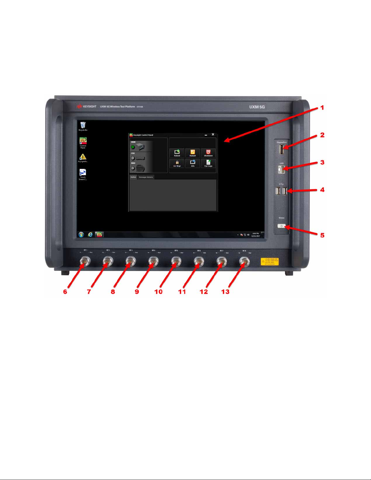
Begin using the UXM 5G by becoming familiar with the layout of the Front
Panel and the displayed user interface.
Figure 5-1 UXM 5G Front Panel
72 Getting Started Guide
Page 73

Front and Rear Panel Functions
Front Panel Features
Number Item Name Description
1 Touch-screen LCD Flat-Panel Display with single touch 15” capacitive touch-screen.
2 DisplayPort This is a DisplayPort output, which transfers uncompressed video and audio
data to an external display, such as a PC monitor or projector.
If a monitor is going to be connected to the DisplayPort, it is preferable to make
this connection while instrument power is off. The monitor is normally
detected by the E7515B’s power-on routine; it can sometimes go undetected if
the connection is made after power is on (if that happens, it will be necessary to
cycle power on the E7515B so that the power-on routine is repeated).
3 Front LAN Connection This RJ-45 connector provides front-panel access from the UXM 5G Host PC
enabling a maximum Ethernet data rate of 1 Gigabit. This connector is used for
downloading firmware upgrades, new test platform applications, saving data to
an external memory drive and other reasons for which you may wish to connect
to a local area network and/or to the internet. See
on page 40
. The IP address for this input is labeled “Front”.
“LAN Connectivity”
4 2 - USB Inputs Universal Serial Bus inputs for peripheral devices (mouse, keyboard, flash
drives). These are USB version 2.0. (See the rear panel for USB 3.0 ports.)
5 Power button
Status light
6 -13 RF1 - RF8 Tx/Rx ports
In/Out lights
The power button is the On/Off button for AC power. Pressing this button when
the instrument is powered off turns it on. Pressing this button briefly will shut
down the UXM 5G and Windows Operating System safely. (Pressing and
holding this button down for more than 5 seconds forces a complete
instrument shut-down, but this is not recommended, as it triggers an
uncontrolled Windows shutdown).
The Status light indicates the power status of the instrument (see
Status Indicator” on page 74
On and line power must be connected in order for this light to illuminate.
These ports transmit and receive using the base station emulator of the UXM
5G.
For each port, two indicators are provided; they are lit when the port is
configured to receive (In), to transmit (Out), or to operate in duplex mode
(both).
For ports RF1 through RF8, the maximum RF power input levels are:
+34 dBm MAX CW
+42 dBm MAX Peak
+
20 VDC MAX
). The rear-panel switch must be turned
“Power
Getting Started Guide 73
Page 74

Front and Rear Panel Functions
Front Panel Features
Power Status Indicator
UXM 5G Power Status
— Off: Back-panel power switch is off.
— Yellow: The rear power switch is on, but the UXM 5G is powered down. The
first time the back-panel power switch is turned on (UXM 5G (front-panel
switch is off). It may display as green when the Micro-Controller Unit is
loading (~3 seconds) after which it remains yellow.
— Green blinking: The UXM 5G is booting up.
— Green: UXM 5G is available for use or in use.
— Green/Yellow blinking: Instrument Control Module (ICM) for the
Micro-Controller Unit is downloading firmware. (Not the FPGA ICM.) When
the FPGA-ICM is downloading firmware, the LED is green.
— Yellow b l inking: UXM 5G is shutting down and the boards shutdown
process has begun.
— Yellow/Orange blinking: UXM 5G is off after an abnormal shutdown.
74 Getting Started Guide
Page 75

Front and Rear Panel Functions
Rear Panel Features
Rear Panel Features
Figure 5-2 UXM 5G Rear Panel
The regions of the rear panel that are outlined in the illustration are described
in the following sections.
Do not cover or block the air flow vents. The test platform draws air in from the
left side and exhausts air from the right side.
The main power cord can be used as the system disconnecting device. It
disconnects the mains circuits from the mains supply.
Getting Started Guide 75
Page 76

Front and Rear Panel Functions
Rear Panel Features
VDTAMC Cards
Figure 5-3 UXM 5G Rear Panel -- VDTAMC card connectors
These connectors relate to the VDTAMC card (of which there are three, in slots
2, 4, and 5) within the UXM 5G.
The VDTAMC card (also known as the Vadatech AMC 702) handles processing
of the PHY and PDCP layers in the simulated 5G NR stack.
Name Description Notes
10GBbE SFP+ connector Usage depends on the hardware configuration selected on the
HCCU Setup tab.
UO, U1, U2, RUN LEDs (Reserved for future use.)
CPU RS-232 Micro-USB connector (Reserved for future use.)
MGT RS-232 Micro-USB connector (Reserved for future use.)
ETH2 RJ-45 connector Usage depends on the hardware configuration selected on the
HCCU Setup tab.
76 Getting Started Guide
Page 77

Front and Rear Panel Functions
Rear Panel Features
CCTAMC Card
Figure 5-4 UXM 5G Rear Panel -- CCTAMC card connectors
These connectors relate to the CCTAMC card within the UXM 5G.
The CCTAMC card (also known as the Concurrent Technologies AMC14)
handles processing of the RLC and MAC layers in the simulated 5G NR stack.
Name Description Notes
USB USB 2.0 connector (Reserved for future use.)
RS-232 IEEE 1394 connector (Reserved for future use.)
ETH2 RJ-45 connector Usage depends on the hardware configuration selected on the
HCCU Setup tab.
ETH3 RJ-45 connector Usage depends on the hardware configuration selected on the
HCCU Setup tab.
Getting Started Guide 77
Page 78

Front and Rear Panel Functions
Rear Panel Features
FPGA Expansion Module (E7515B-FP1)
Figure 5-5 UXM 5G Rear Panel -- E7515B-FP1 card connectors
These connectors relate to the optional FPGA expansion module
(E7515B-FP1), of which there are potentially two, located in slots 1 and 3.
These modules expand the FPGA capacity of the E7515B, for certain kinds of
5G testing which require this.
Name Description Notes
QSFP1 Kintex-A QSFP Interface Reserved for future use.
QSFP0 Kintex-A QSFP Interface Reserved for future use.
TRIG 1 TBD Reserved for future use.
DEBUG TBD Reserved for future use.
TRIG 0 TBD Reserved for future use.
78 Getting Started Guide
Page 79

Front and Rear Panel Functions
Rear Panel Features
AUXM Connectors
Figure 5-6 UXM 5G Rear Panel -- AUXM Connectors
These connectors relate to the AUXM circuit board within the UXM 5G.
Name Description Notes
I/0 1
I/O 2
AUX 1
AUX 2
STATUS 1
STATUS 2
10 MHz IN
10 MHz OUT
SYNCH 1
SYNCH 2
SYNCH 3
SMA connectors (Reserved for future use.)
SMA connectors (Reserved for future use.)
LEDs (Reserved for future use.)
SMA Input/Output
10 MHz clock reference
Mini-SAS
HD 4x
Do not modify connections to the internal and/or external
references while this instrument is transmitting or receiving RF
signals.
Synchronizes the internal clocks between arrays of UXM 5G
units.
Getting Started Guide 79
Page 80

Front and Rear Panel Functions
Rear Panel Features
ICM Connectors
Figure 5-7 UXM 5G Rear Panel -- ICM Connectors
These connectors relate to the AUXM circuit board within the UXM 5G.
Name Description Notes
GbE 4 This is the Ethernet port that
is connected internally to the
UXM 5G Host PC. Use this
port to connect the UXM 5G
to the LAN.
I/O 1
I/O 2
STATUS 1
STATUS 2
AUX 1 (Reserved for future use.)
GbE 1
GbE 2
GbE 3
Mini-SAS 28AWG Used to interconnect multiple UXM units.
LEDs (Reserved for future use.)
Ethernet GbE 1, GbE 2, and
GbE 3
The IP address for this input is labeled “ICM GbE4”.
Used only by Keysight during production or maintenance..
80 Getting Started Guide
Page 81

Front and Rear Panel Functions
Rear Panel Features
DCB+ Connectors
Figure 5-8 UXM 5G Rear Panel -- DCB+ Connectors
These connectors relate to the DCB+ circuit board within the UXM 5G. (There is
a second board, with an identical set of connectors for it.)
Name Description Notes
LAN RJ-45 (Reserved for future use.)
TRIG_B1 SMA Input/output triggers
ZQ, KB, KA Indicators LEDs (Reserved for future use.)
TRIG_B2 SMA Input/output triggers
DBG (Reserved for future use.)
TRIG_A1 SMA Input/output triggers
MMC A, B, C
Indicators
TRIG_A2 SMA Input/output triggers
SPI MASTER
SPI SLAVE
BNC1
BNC2
FMC BBIQ connectors (Optional)
LEDs (Reserved for future use.)
Synchronism ports
Input/output triggers
Getting Started Guide 81
Page 82

Front and Rear Panel Functions
Rear Panel Features
PCM
Figure 5-9 UXM 5G Rear Panel -- PCM Connectors
These connectors relate to the DCB+ circuit board within the UXM 5G.
Name Description Notes
SS USB Four USB 3.0 ports. (The front-panel USB ports are USB 2.0.)
Audio In 3.5 mm stereo Audio jack connector for input.
Audio Out 3.5 mm stereo Audio jack connector for output.
82 Getting Started Guide
Page 83

Front and Rear Panel Functions
Rear Panel Features
RFIO
Figure 5-10 UXM 5G Rear Panel -- RFIO Connectors
These connectors relate to the RFIO circuit board within the UXM 5G.
Name Description Notes
IF IN 3 SMA (Reserved for future use.)
IF IN 4 SMA (Reserved for future use.)
IF OUT 8 SMA (Reserved for future use.)
IF OUT 7 SMA (Reserved for future use.)
IF OUT 6 SMA (Reserved for future use.)
IF OUT 5 SMA (Reserved for future use.)
IF IN 1 SMA (Reserved for future use.)
IF IN 2 SMA (Reserved for future use.)
IF OUT 4 SMA (Reserved for future use.)
IF OUT 3 SMA (Reserved for future use.)
IF OUT 2 SMA (Reserved for future use.)
IF OUT 1 SMA (Reserved for future use.)
AC Power
Removing the main power cord disconnects the mains circuits from the mains
supply, and can be used as the system disconnecting device.
Getting Started Guide 83
Page 84

Front and Rear Panel Functions
Front and Rear Panel Symbols
Front and Rear Panel Symbols
Symbol Description
This symbol is used to indicate power ON.
This symbol is used to indicate power OFF.
This symbol is used to indicate power STANDBY mode (yellow in standby, green when instrument
is ON).
This symbol indicates the input power required is AC.
This symbol indicates earth ground.
The instruction documentation symbol. The product is marked with this symbol when it is
necessary for the user to refer to instructions in the documentation.
The CE mark is a registered trademark of the European Community.
The RCM Mark is a Compliance Mark according to the ACMA Labeling Requirement.
South Korean Certification (KC) mark; includes the marking’s identifier code which follows this
format: MSIP-REM-YYY-ZZZZZZZZZZZZZZ
ICES / NMB-001 Cet appareil ISM est conforme a la norme NMB du Canada. This is a marking to
indicate product compliance with the Industry Canadian Interference-Causing Equipment
Standard (ICES-001).
This is also a symbol of an Industrial Scientific and Medical Group 1 Class A product (CISPR 11,
Clause 4).
The CSA mark is a registered trademark of the CSA International.
This symbol indicates separate collection for electrical and electronic equipment mandated under
EU law as of August 13, 2005. All electric and electronic equipment are required to be separated
from normal waste for disposal (Reference WEEE Directive 2002/96/EC).
84 Getting Started Guide
Page 85

Front and Rear Panel Functions
Front and Rear Panel Symbols
Symbol Description
Indicates the time period during which no hazardous or toxic substance elements are expected to
leak or deteriorate during normal use. Forty years is the expected useful life of the product.
This symbol on all primary and secondary packaging indicates compliance to China standard GB
18455-2001.
Getting Started Guide 85
Page 86

Front and Rear Panel Functions
Front and Rear Panel Symbols
86 Getting Started Guide
Page 87

Keysight Wireless Test Set
E7515B UXM 5G Wireless Test Set Platform
Getting Started Guide
6 Test Platform Operating System
The following topics can be found in this section:
“Keysight Software Installed” on page 88
“User Accounts” on page 89
“System Maintenance” on page 93
Updating the Keysight E7515B UXM 5G software on page 99
Updating the Keysight 5G NR Test Application on page 101
87
Page 88

Test Platform Operating System
Keysight Software Installed
Keysight Software Installed
Your test platform has a software application already installed: the C8700200A Test
Application Framework.
Customer Installation of Software
If for some reason you need to re-install any software you purchased, go to
www.keysight.com/find/softwaremanager to obtain the latest version.
Refer to Chapter , “Updating the Keysight E7515B UXM 5G software”, on
page 99 for software installation instructions.
Uninstalling Keysight Software
Uninstallation is a dialog driven process. You can access the uninstall dialog of
the Keysight Test Application software within the Windows Start menu, or by
using the Start > Control Panel\All Control Panel Items\Programs and
Features dialog within Windows.
Installation of Third Party Software
It is recommended that you do not install any non-approved software on the
UXM 5G. Installation of third party software on the UXM 5G may render the
system inoperative and is not supported by Keysight Technologies.
88 Getting Started Guide
Page 89

User Accounts
Administrator Account
Test Platform Operating System
User Accounts
The E7515B ships with only one account set up (the Administrator account).
Setting up additional user accounts is not recommended, as this would likely
create problems of compatibility with the installed firmware.
Using the Administrator account you can perform the following operations:
—Install software
— Configure network and printer access
— Access all files on the instrument
— Add or change user accounts and passwords (see “Changing Account
Passwords” on page 90).
— Change Firewall settings
— Change Windows settings (e.g., using Device Manager)
— Change the time and date
—Run Keysight applications
For instruments with a Keysight Technologies disk image, the Administrator
account ships from the factory with the password set as:
Keysight4u!
Getting Started Guide 89
Page 90

Test Platform Operating System
User Accounts
Changing Account Passwords
In order to minimize an “unnoticed” or “involuntary” change of the
Administrator account password, the account properties have been set to
restrict password change. If you need to change the password for this account,
proceed as follows:
Step Notes
1. Log in to the
instrument as
Administrator.
2. Use the Windows
Search icon in the
lower left of the
desktop to search for
(and select)
Administrative
.
Tools
3. Locate and select
Computer
Management
.
90 Getting Started Guide
Page 91

Test Platform Operating System
User Accounts
Step Notes
4. Locate and select
Users
a.
b.
Administrator
c.
More Actions
d.
Properties
5. Clear the check box
next to “User cannot
change password”
and then select
OK.
Getting Started Guide 91
Page 92

Test Platform Operating System
User Accounts
Step Notes
6. After you have
changed the
Administrator
Properties, change
your password by
pressing
Ctrl+Alt+Del then
Change Password.
7. Enter the password
change information.
a. The account to be
changed
("Administrator").
b. The old password
c. The new password.
d. Re-enter the new
password to confirm.
(Complete the
operation by
pressing Enter or
clicking the arrow
icon.)
8. After changing the
password(s), repeat
steps 2 through 8.
92 Getting Started Guide
After changing the password(s), it is recommended that you restore the "User cannot
change password" Administrator property (see step 8).
Page 93

Test Platform Operating System
System Maintenance
System Maintenance
Back-up
It is recommended that you have a regular back-up strategy. Your IT
department may already have a back-up strategy in place which is suitable for
the test platform and its data.
The Windows 10 operating system has a Backup utility that you can use to
archive files and folders in case of a hard disk drive failure. See the Microsoft
Windows Help and Support Center for more information on this utility.
When performing back-ups, we recommend that you back-up the data to an
external storage device connected to your company’s internal network or one
of the test platform’s USB connectors. Also, you should perform back-ups at
times when the Server PC is not being used for normal operations as it may
impact the test platform’s overall performance.
System Restore
Windows 10 contains the capability to restore the system to a previous point in
time. System Restore is enabled with default settings as provided by Microsoft.
However, System Restore is not 100% successful. Therefore, it is not the
recommended method to back-up the instrument. System Restore has not
been tested to verify successful restoring. It is best to use the procedure
described in “Disk Drive Recovery Process” on page 95.
Getting Started Guide 93
Page 94

Test Platform Operating System
System Maintenance
Hard Drive Partitioning and Use
The drive is partitioned into 3 sections: C:, D: and E:
—The C: partition contains the Windows 10 operating system and software
installed by Keysight. This is an Open System which means you can install
additional software. However it is recommended that you use an external
PC to host all additional software applications that you wish to use in
conjunction with the UXM 5G. The installation and/or use of other software
is not warranted and could interfere with the operation of the test platform
software. If instrument repair is ever needed, the Keysight version of the C:
drive is the only part of the instrument software that is restored by the
Instrument Image Recovery System. You must reload any other software
that you have added in the instrument.
It is recommended that you use an external PC to host software applications you
wish to use in conjunction with the UXM 5G. Installing applications on the
instrument Host PC may result in a compromised performance of the UXM 5G
including decreased throughput and/or measurement performance.
—The D: partition is reserved for data storage. This is for the convenience of
backing-up the test platform measurement data. You should always
back-up the data on the D: drive to an external device. This enables you to
restore the data should the hard drive need to be replaced.e
Data on the desktop will be deleted during system recovery. Therefore it is
recommended that you always store your data in another folder on the D: drive,
for example D:\MyData
—The E: partition is reserved for Keysight’s use. The primary use of the E:
drive is for storing the Calibration and Alignment data, the configuration
files for the Platform Boards and Host PC. Do not change or overwrite the
files on this drive. This could cause your instrument to not meet
specifications, or even to stop functioning correctly. Do not use this drive
for data storage. It is also recommended that you back-up the contents of
this drive by using an external device.
94 Getting Started Guide
Page 95

Test Platform Operating System
System Maintenance
Disk Drive Recovery Process
The Instrument Image Recovery System can be used to repair errors on the
instrument’s C: drive or to restore the original factory configuration of the
system software. Repairing errors on the hard disk drive may result in loss of
data or files. If you need more information about the Windows "chkdsk" error
repair process, see the chkdsk documentation in the Microsoft Windows 10
Help and Support Center.
This recovery process should only be used for the repair/restoration purposes
described above. It is not suitable for performing an instrument software update;
“Updating the Keysight E7515B UXM 5G software” on
see
page 99
Restoring the original factory system software does not restore any of the
following items:
— Windows system configurations that were made after the instrument was
shipped from the factory. For example, Windows and Service Pack updates,
user accounts, and Windows configuration settings. After an Instrument
Image Recovery System, these configurations need to be redone.
for the appropriate procedure.
— Additional software that was installed after the instrument was shipped
from the factory. After an Instrument Image Recovery System, that software
needs to be re-installed.
— Any upgrades that were made to the Keysight Test Application software.
It is recommended that you use a regular back-up strategy. Your IT department
may already have a back-up strategy in place which is suitable for the Internal
Applications Server and its data. See
the Instrument Image Recovery System in conjunction with a regular back-up
strategy should allow you to fully recover the Internal Applications Server
software and data.
“User Accounts” on page 89. Using
It is recommended that routine back-ups of the instrument information be
performed to keep current archives of the instrument information. This allows a
full recovery of the instrument information after the instrument recovery
system operations are performed. See “Back-up” on page 93 for more details.
Getting Started Guide 95
Page 96

Test Platform Operating System
System Maintenance
Using the Instrument Image Recovery System - Test Platform
Operating System
Step Notes
1. Turn on the
instrument.
Press the down arrow
key to move the
highlight to
Instrument
Image
Recovery System
and then press
2. After selecting the
Enter.
Instrument Image
Recovery System
the instrument boots
the
Instrument
Image Recovery
System
minutes. Finally, the
instrument displays a
message asking if you
would like to review
the Keysight license
agreement. Select
for 2 or 3
Yes.
The Windows Boot Manager Screen is displayed.
,
,
96 Getting Started Guide
Page 97

Test Platform Operating System
System Maintenance
Step Notes
3. Review the terms.
Select the “X” in the
upper right corner to
close this window.
4. Accept the license
agreement by
selecting
Yes.
Getting Started Guide 97
Page 98

Test Platform Operating System
System Maintenance
Step Notes
5. When the
Instrument Image
Recovery System
has booted, follow
the on-screen
instructions to
recover the image of
the C: drive.
Type in the number
then press
select “Recovery of
the original factory
system image”.
6. A warning message
appears. Press
start the recovery,
which may take up to
45 minutes to
complete.
OK to
OK to
2,
7. The instrument then
re-executes the
process described
under:
“Turning On
the Test Platform
the First Time” on
page 30
98 Getting Started Guide
.
Page 99

Test Platform Operating System
Updating the Keysight E7515B UXM 5G software
Updating the Keysight E7515B UXM 5G software
The following steps are required to upgrade your Keysight E7515B UXM 5G
firmware. Downgrading to an earlier version is also possible, using the same
process.
Using the E7515B/E7515B UXM 5G Firmware Update Tool
Step Notes
1. Connect a USB keyboard and
mouse to the instrument
2. Log in as follows:
User Name: administrator
Password: Keysight4u!
3. Obtain the latest version of
software installer.
4. Launch
from the Windows menu at the
lower left corner of the desktop (it
should be under
E7515B UXM 5G
Firmware Upgrade Tool
Keysight
).
Download it from the site:
www.keysight.com/find/softwaremanager
If this application is not installed, download the latest recommended
version of “Keysight E7515B/E7515B UXM 5G Firmware UpdateTool”
from the site:
www.keysight.com/find/softwaremanager
5. In the “UXM 5G Update Tool” add
the software installer program
obtained in the step 4.
6. Select the desired software
installer and click the
UXM5G Firmware
7. When prompted to continue with
the Firmware update, select
8. If a system restart is required, a
confirmation message will appear
when restart is needed. In that
case, when prompted to continue
with the restart, select
Getting Started Guide 99
Update
button.
Yes.
Yes.
Right-click on the Windows “Select firmware version:” and Add it.
If the instrument belongs to an Array, the instrument is exited from
Array.
The Firmware Update Tool will warn if a system restart is required for
completing the uninstallation/installation.
This typically happens when Microsoft .NET Framework must be
updated.
Page 100

Test Platform Operating System
Updating the Keysight E7515B UXM 5G software
Step Notes
9. The “UXM5G Update Tool” will
continue by itself after the
instrument restarts, and will finish
the update. Then a confirmation
button will be shown.
10. In case of an error during
upgrade, the “UXM5G
UpdateTool” will inform the user.
In that case, you can try to repair
it manually or contact Support
team.
To manually repair the software upgrade, go to “Control
Panel\Programs\Programs and Features” and:
(a) Uninstall Keysight E7515B Application
(b) Uninstall Keysight E7515B UXM 5G
(c) Repeat the upgrade from step 5 above.
If this is not successful, you must contact the Support team.
100 Getting Started Guide
 Loading...