

Page 1

Keysight E5061B Network Analyzer
Service Guide
Page 2

Notices
© Keysight Technologies
2009-2019
No part of this manual may be
reproduced in any form or by any
means (including electronic storage
and retrieval or translation into a
foreign language) without prior
agreement and written consent from
Keysight Technologies, Inc. as
governed by United States and
international copyright laws.
Trademark Acknowledgments
Manual Part Number
E5061-90105
Edition
Edition 4, June 2019
COVERING THE MATERIAL IN THIS
DOCUMENT THAT CONFLICT WITH
THESE TERMS, THE WARRANTY
TERMS IN THE SEPARATE
AGREEMENT WILL CONTROL.
Technology Licenses
The hardware and/or software
described in this document are
furnished under a license and may be
used or copied only in accordance
with the terms of such license.
Declaration of Conformity
Declarations of Conformity for this
product and for other Keysight
products may be downloaded from
the Web. Go to
http://www.keysight.com/go/confor
mity. You can then search by product
number to find the latest Declaration
of Conformity.
perform, display, or disclose
commercial computer software or
commercial computer software
documentation. No additional
government requirements beyond
those set forth in the EULA shall
apply, except to the extent that those
terms, rights, or licenses are
explicitly required from all providers
of commercial computer software
pursuant to the FAR and the DFARS
and are set forth specifically in
writing elsewhere in the EULA.
Keysight shall be under no obligation
to update, revise or otherwise modify
the Software. With respect to any
technical data as defined by FAR
2.101, pursuant to FAR 12.211 and
27.404.2 and DFARS 227.7102, the
U.S. government acquires no greater
than Limited Rights as defined in FAR
27.401 or DFAR 227.7103-5 (c), as
applicable in any technical data.
Printed in Malaysia
Published by:
Keysight Technologies International
Japan G.K,
1-3-3 Higashikawasaki-cho
Chuo-ku
Kobe-shi, Hyogo, Japan
Warranty
THE MATERIAL CONTAINED IN THIS
DOCUMENT IS PROVIDED “AS IS,”
AND IS SUBJECT TO BEING
CHANGED, WITHOUT NOTICE, IN
FUTURE EDITIONS. FURTHER, TO
THE MAXIMUM EXTENT PERMITTED
BY APPLICABLE LAW, KEYSIGHT
DISCLAIMS ALL WARRANTIES,
EITHER EXPRESS OR IMPLIED WITH
REGARD TO THIS MANUAL AND
ANY INFORMATION CONTAINED
HEREIN, INCLUDING BUT NOT
LIMITED TO THE IMPLIED
WARRANTIES OF
MERCHANTABILITY AND FITNESS
FOR A PARTICULAR PURPOSE.
KEYSIGHT SHALL NOT BE LIABLE
FOR ERRORS OR FOR INCIDENTAL
OR CONSEQUENTIAL DAMAGES IN
CONNECTION WITH THE
FURNISHING, USE, OR
PERFORMANCE OF THIS
DOCUMENT OR ANY INFORMATION
CONTAINED HEREIN. SHOULD
KEYSIGHT AND THE USER HAVE A
SEPARATE WRITTEN AGREEMENT
WITH WARRANTY TERMS
U.S. Government Rights
The Software is “commercial
computer software,” as defined by
Federal Acquisition Regulation
(“FAR”) 2.101. Pursuant to FAR
12.212 and 27.405-3 and
Department of Defense FAR
Supplement (“DFARS”) 227.7202, the
U.S. government acquires
commercial computer software
under the same terms by which the
software is customarily provided to
the public. Accordingly, Keysight
provides the Software to U.S.
government customers under its
standard commercial license, which
is embodied in its End User License
Agreement (EULA), a copy of which
can be found at
http://www.keysight.com/find/sweul
a The license set forth in the EULA
represents the exclusive authority by
which the U.S. government may use,
modify, distribute, or disclose the
Software. The EULA and the license
set forth therein, does not require or
permit, among other things, that
Keysight: (1) Furnish technical
information related to commercial
computer software or commercial
computer software documentation
that is not customarily provided to
the public; or (2) Relinquish to, or
otherwise provide, the government
rights in excess of these rights
customarily provided to the public to
use, modify, reproduce, release,
Safety Notices
A CAUTION notice denotes a hazard. It
calls attention to an operating
procedure, practice, or the like that,
if not correctly performed or adhered
to, could result in damage to the
product or loss of important data. Do
not proceed beyond a CAUTION
notice until the indicated conditions
are fully understood and met.
A WARNING notice denotes a hazard.
It calls attention to an operating
procedure, practice, or the like that,
if not correctly performed or adhered
to, could result in personal injury or
death. Do not proceed beyond a
WARNING notice until the indicated
conditions are fully understood and
met.
Page 3
Caution
Keysight E5061B Network Analyzer
Service Guide
Do not exceed the operating input power, voltage, and current level and signal
type appropriate for the instrument being used, refer to your instrument’s
Function Reference.
Electrostatic discharge (ESD) can damage the highly sensitive microcircuits in
your instrument. ESD damage is most likely to occur as the test fixtures are
being connected or disconnected. Protect them from ESD damage by wearing
a grounding strap that provides a high resistance path to ground. Alternatively,
ground yourself to discharge any static charge built-up by touching the outer
shell of any grounded instrument chassis before touching the test port
connectors.
Safety Summary
The following general safety precautions must be observed during all phases of
operation, service, and repair of this instrument. Failure to comply with these
precautions or with specific WARNINGS elsewhere in this manual may impair
the protection provided by the equipment. Such noncompliance would also
violate safety standards of design, manufacture, and intended use of the
instrument. Keysight Technologies assumes no liability for the customer’s
failure to comply with these precautions.
The E5061B complies with INSTALLATION CATEGORY II as well as
POLLUTION DEGREE 2 in IEC61010-1. The E5061B is an INDOOR USE
product.
The LEDs in the E5061B are Class 1 in accordance with IEC60825-1,
CLASS 1 LED PRODUCT
This equipment is MEASUREMENT CATEGORY I (CAT I). Do not use for CAT
II, III, or IV.
3
Page 4

-
Caution
Safety Summary
This equipment is tested with stand-alone condition or with the
combination with the accessories supplied by Keysight Technologies
against the requirement of the standards described in the Declaration of
Conformity. If it is used as a system component, compliance of related
regulations and safety requirements are to be confirmed by the builder of
the system.
• Ground the Instrument
To avoid electric shock, the instrument chassis and cabinet must be
grounded with the supplied power cable’s grounding prong.
• Do NOT Operate in an Explosive Atmosphere
Do not operate the instrument in the presence of inflammable gases or
fumes. Operation of any electrical instrument in such an environment
clearly constitutes a safety hazard.
• Keep Away from Live Circuits
Operators must not remove instrument covers. Component replacement
and internal adjustments must be made by qualified maintenance
personnel. Do not replace components with the power cable connected.
Under certain conditions, dangerous voltage levels may remain even after
the power cable has been disconnected. To avoid injuries, always
disconnect the power and discharge circuits before touching them.
• DO NOT Service or Adjust the Instrument Alone
Do not attempt internal service or adjustment unless another person,
capable of rendering first aid and resuscitation, is present.
• Do NOT Substitute Parts or Modify the Instrument
To avoid the danger of introducing additional hazards, do not install
substitute parts or perform unauthorized modifications to the instrument.
Return the instrument to a Keysight Technologies Sales and Service Office
for service and repair to ensure that safety features are maintained in
operational condition.
• Dangerous Procedure Warnings
Warnings, such as the example below, precede potentially dangerous
procedures throughout this manual. Instructions contained in the warnings
must be followed.
Dangerous voltage levels, capable of causing death, are present in this
instrument. Use extreme caution when handling, testing, and adjusting
this instrument.
• Do not connect the measuring terminals to mains.
4 Keysight E5061B Network Analyzer
Page 5

Safety Symbols
Caution
Safety Symbols
General definitions of safety symbols used on the instrument or in manuals are
listed below.
Instruction Manual symbol: the product is marked with this
symbol when it is necessary for the user to refer to the instrument
manual.
Alternating current.
Direct current.
On (Supply).
Off (Supply).
Certification
Keysight Technologies certifies that this product met its published
specifications at the time of shipment from the factory. Keysight Technologies
further certifies that its calibration measurements are traceable to the United
States National Institute of Standards and Technology, to the extent allowed
by the Institution’s calibration facility or by the calibration facilities of other
International Standards Organization members.
Exclusive Remedies
The remedies provided herein are Buyer’s sole and exclusive remedies.
Keysight Technologies shall not be liable for any direct, indirect, special,
incidental, or consequential damages, whether based on contract, tort, or any
other legal theory.
A chassis terminal; a connection to the instrument’s chassis,
which includes all exposed metal structure.
Standby.
Assistance
Product maintenance agreements and other customer assistance agreements
are available for Keysight Technologies products.
Keysight E5061B Network Analyzer 5
Page 6

-
Caution
Safety Symbols
For any assistance, contact your nearest Keysight Technologies Sales and
Service Office. Addresses are provided at the back of this manual.
6 Keysight E5061B Network Analyzer
Page 7

Table of Contents
Caution . . . . . . . . . . . . . . . . . . . . . . . . . . . . . . . . . . . . . . . . . . . . . . . . . . . . . . . . . . . . . . . . . . . . 3
Safety Summary . . . . . . . . . . . . . . . . . . . . . . . . . . . . . . . . . . . . . . . . . . . . . . . . . . . . . . . . . . . . . 3
Safety Symbols . . . . . . . . . . . . . . . . . . . . . . . . . . . . . . . . . . . . . . . . . . . . . . . . . . . . . . . . . . . . . . 5
Certification . . . . . . . . . . . . . . . . . . . . . . . . . . . . . . . . . . . . . . . . . . . . . . . . . . . . . . . . . . . . . 5
Exclusive Remedies . . . . . . . . . . . . . . . . . . . . . . . . . . . . . . . . . . . . . . . . . . . . . . . . . . . . . . . 5
Assistance. . . . . . . . . . . . . . . . . . . . . . . . . . . . . . . . . . . . . . . . . . . . . . . . . . . . . . . . . . . . . . . 5
1. General Information
Precautions. . . . . . . . . . . . . . . . . . . . . . . . . . . . . . . . . . . . . . . . . . . . . . . . . . . . . . . . . . . . . . . . 13
Software Installed. . . . . . . . . . . . . . . . . . . . . . . . . . . . . . . . . . . . . . . . . . . . . . . . . . . . . . . . 13
Organization of Service Guide . . . . . . . . . . . . . . . . . . . . . . . . . . . . . . . . . . . . . . . . . . . . . . . . . 14
Instrument Covered by This Manual . . . . . . . . . . . . . . . . . . . . . . . . . . . . . . . . . . . . . . . . . . . . 15
Required Equipment. . . . . . . . . . . . . . . . . . . . . . . . . . . . . . . . . . . . . . . . . . . . . . . . . . . . . . . . . 16
Contents
2. Troubleshooting
Introduction . . . . . . . . . . . . . . . . . . . . . . . . . . . . . . . . . . . . . . . . . . . . . . . . . . . . . . . . . . . . . . . 19
How to exit from the E5061B Measurement View . . . . . . . . . . . . . . . . . . . . . . . . . . . . . . . . . . 20
To Troubleshoot the Instrument . . . . . . . . . . . . . . . . . . . . . . . . . . . . . . . . . . . . . . . . . . . . . . . . 21
Primary Trouble Isolation . . . . . . . . . . . . . . . . . . . . . . . . . . . . . . . . . . . . . . . . . . . . . . . . . . 21
No Display Troubleshooting . . . . . . . . . . . . . . . . . . . . . . . . . . . . . . . . . . . . . . . . . . . . . . . . . . . 23
Booting Process Troubleshooting. . . . . . . . . . . . . . . . . . . . . . . . . . . . . . . . . . . . . . . . . . . . . . . 27
Troubleshooting Using Diagnostic Test . . . . . . . . . . . . . . . . . . . . . . . . . . . . . . . . . . . . . . . . . . 32
Power On Self Test . . . . . . . . . . . . . . . . . . . . . . . . . . . . . . . . . . . . . . . . . . . . . . . . . . . . . . . 32
PLL unlock . . . . . . . . . . . . . . . . . . . . . . . . . . . . . . . . . . . . . . . . . . . . . . . . . . . . . . . . . . . . . 32
Contents of the diagnostic test . . . . . . . . . . . . . . . . . . . . . . . . . . . . . . . . . . . . . . . . . . . . . 32
Test equipment required for diagnostic test . . . . . . . . . . . . . . . . . . . . . . . . . . . . . . . . . . . 33
To Execute the Diagnostic Test . . . . . . . . . . . . . . . . . . . . . . . . . . . . . . . . . . . . . . . . . . . . . 33
Program Overall . . . . . . . . . . . . . . . . . . . . . . . . . . . . . . . . . . . . . . . . . . . . . . . . . . . . . . . . . 35
Diagnostic Test Failure Troubleshooting . . . . . . . . . . . . . . . . . . . . . . . . . . . . . . . . . . . . . . 36
Function Specific Troubleshooting. . . . . . . . . . . . . . . . . . . . . . . . . . . . . . . . . . . . . . . . . . . . . . 39
To Check the Device Driver . . . . . . . . . . . . . . . . . . . . . . . . . . . . . . . . . . . . . . . . . . . . . . . . 40
To Check the Front Panel . . . . . . . . . . . . . . . . . . . . . . . . . . . . . . . . . . . . . . . . . . . . . . . . . . 42
To Check the Touch Panel . . . . . . . . . . . . . . . . . . . . . . . . . . . . . . . . . . . . . . . . . . . . . . . . . 42
To Check the LCD. . . . . . . . . . . . . . . . . . . . . . . . . . . . . . . . . . . . . . . . . . . . . . . . . . . . . . . . 43
To Check the External Keyboard . . . . . . . . . . . . . . . . . . . . . . . . . . . . . . . . . . . . . . . . . . . . 43
To Check the Mouse. . . . . . . . . . . . . . . . . . . . . . . . . . . . . . . . . . . . . . . . . . . . . . . . . . . . . . 43
To Check the Video output. . . . . . . . . . . . . . . . . . . . . . . . . . . . . . . . . . . . . . . . . . . . . . . . . 44
To Check the External Trigger Input. . . . . . . . . . . . . . . . . . . . . . . . . . . . . . . . . . . . . . . . . . 44
Keysight E5061B Service Guide 7
Page 8

Contents
To Check the GPIB. . . . . . . . . . . . . . . . . . . . . . . . . . . . . . . . . . . . . . . . . . . . . . . . . . . . . . . .44
To Check the USB . . . . . . . . . . . . . . . . . . . . . . . . . . . . . . . . . . . . . . . . . . . . . . . . . . . . . . . .45
Performance Test failure Troubleshooting. . . . . . . . . . . . . . . . . . . . . . . . . . . . . . . . . . . . . . . . .46
Recommended adjustment for Performance Test failure . . . . . . . . . . . . . . . . . . . . . . . . . . 46
Performance Test failure Troubleshooting. . . . . . . . . . . . . . . . . . . . . . . . . . . . . . . . . . . . . .48
3. Replaceable Parts
Ordering Information . . . . . . . . . . . . . . . . . . . . . . . . . . . . . . . . . . . . . . . . . . . . . . . . . . . . . . . . . 51
Direct Mail Order System . . . . . . . . . . . . . . . . . . . . . . . . . . . . . . . . . . . . . . . . . . . . . . . . . .51
Exchange Assemblies . . . . . . . . . . . . . . . . . . . . . . . . . . . . . . . . . . . . . . . . . . . . . . . . . . . . . . . .52
Replaceable Parts List . . . . . . . . . . . . . . . . . . . . . . . . . . . . . . . . . . . . . . . . . . . . . . . . . . . . . . . . 52
4. Replacement Procedure
Replacing an Assembly . . . . . . . . . . . . . . . . . . . . . . . . . . . . . . . . . . . . . . . . . . . . . . . . . . . . . . .53
Required Tools . . . . . . . . . . . . . . . . . . . . . . . . . . . . . . . . . . . . . . . . . . . . . . . . . . . . . . . . . . . . . .54
Outer Cover Replacement . . . . . . . . . . . . . . . . . . . . . . . . . . . . . . . . . . . . . . . . . . . . . . . . . . . . .55
Tools Required . . . . . . . . . . . . . . . . . . . . . . . . . . . . . . . . . . . . . . . . . . . . . . . . . . . . . . . . . . . 55
Removal Procedure . . . . . . . . . . . . . . . . . . . . . . . . . . . . . . . . . . . . . . . . . . . . . . . . . . . . . . .55
Replacement Procedure . . . . . . . . . . . . . . . . . . . . . . . . . . . . . . . . . . . . . . . . . . . . . . . . . . .55
Front Panel Replacement . . . . . . . . . . . . . . . . . . . . . . . . . . . . . . . . . . . . . . . . . . . . . . . . . . . . .56
Tools required . . . . . . . . . . . . . . . . . . . . . . . . . . . . . . . . . . . . . . . . . . . . . . . . . . . . . . . . . . .56
Removal Procedure . . . . . . . . . . . . . . . . . . . . . . . . . . . . . . . . . . . . . . . . . . . . . . . . . . . . . . .56
Replacement Procedure . . . . . . . . . . . . . . . . . . . . . . . . . . . . . . . . . . . . . . . . . . . . . . . . . . .56
Hard Disk Assembly Replacement (Option 019). . . . . . . . . . . . . . . . . . . . . . . . . . . . . . . . . . . .58
Tools Required . . . . . . . . . . . . . . . . . . . . . . . . . . . . . . . . . . . . . . . . . . . . . . . . . . . . . . . . . . .58
Removal Procedure . . . . . . . . . . . . . . . . . . . . . . . . . . . . . . . . . . . . . . . . . . . . . . . . . . . . . . .58
Replacement Procedure . . . . . . . . . . . . . . . . . . . . . . . . . . . . . . . . . . . . . . . . . . . . . . . . . . .58
Hard Disk Assembly Replacement (Option 020). . . . . . . . . . . . . . . . . . . . . . . . . . . . . . . . . . . .60
Tools Required . . . . . . . . . . . . . . . . . . . . . . . . . . . . . . . . . . . . . . . . . . . . . . . . . . . . . . . . . . .60
Removal Procedure . . . . . . . . . . . . . . . . . . . . . . . . . . . . . . . . . . . . . . . . . . . . . . . . . . . . . . .60
Replacement Procedure . . . . . . . . . . . . . . . . . . . . . . . . . . . . . . . . . . . . . . . . . . . . . . . . . . .60
Power Supply Assembly Replacement . . . . . . . . . . . . . . . . . . . . . . . . . . . . . . . . . . . . . . . . . . .62
Tools Required . . . . . . . . . . . . . . . . . . . . . . . . . . . . . . . . . . . . . . . . . . . . . . . . . . . . . . . . . . .62
Removal Procedure . . . . . . . . . . . . . . . . . . . . . . . . . . . . . . . . . . . . . . . . . . . . . . . . . . . . . . .62
Replacement Procedure . . . . . . . . . . . . . . . . . . . . . . . . . . . . . . . . . . . . . . . . . . . . . . . . . . .62
A50 CPU Module Replacement. . . . . . . . . . . . . . . . . . . . . . . . . . . . . . . . . . . . . . . . . . . . . . . . .64
Tools Required . . . . . . . . . . . . . . . . . . . . . . . . . . . . . . . . . . . . . . . . . . . . . . . . . . . . . . . . . . .64
Removal Procedure . . . . . . . . . . . . . . . . . . . . . . . . . . . . . . . . . . . . . . . . . . . . . . . . . . . . . . .64
Replacement Procedure . . . . . . . . . . . . . . . . . . . . . . . . . . . . . . . . . . . . . . . . . . . . . . . . . . .64
A60 CPU Module Replacement. . . . . . . . . . . . . . . . . . . . . . . . . . . . . . . . . . . . . . . . . . . . . . . . .66
Tools Required . . . . . . . . . . . . . . . . . . . . . . . . . . . . . . . . . . . . . . . . . . . . . . . . . . . . . . . . . . .66
8 Keysight E5061B Service Guide
Page 9

Contents
Removal Procedure . . . . . . . . . . . . . . . . . . . . . . . . . . . . . . . . . . . . . . . . . . . . . . . . . . . . . . 66
Replacement Procedure. . . . . . . . . . . . . . . . . . . . . . . . . . . . . . . . . . . . . . . . . . . . . . . . . . . 66
24 Bit I/O Assembly Replacement . . . . . . . . . . . . . . . . . . . . . . . . . . . . . . . . . . . . . . . . . . . . . . 68
Tools Required . . . . . . . . . . . . . . . . . . . . . . . . . . . . . . . . . . . . . . . . . . . . . . . . . . . . . . . . . . 68
Removal Procedure . . . . . . . . . . . . . . . . . . . . . . . . . . . . . . . . . . . . . . . . . . . . . . . . . . . . . . 68
Replacement Procedure. . . . . . . . . . . . . . . . . . . . . . . . . . . . . . . . . . . . . . . . . . . . . . . . . . . 68
DSP Assembly Replacement . . . . . . . . . . . . . . . . . . . . . . . . . . . . . . . . . . . . . . . . . . . . . . . . . . 70
Tools Required . . . . . . . . . . . . . . . . . . . . . . . . . . . . . . . . . . . . . . . . . . . . . . . . . . . . . . . . . . 70
Removal Procedure . . . . . . . . . . . . . . . . . . . . . . . . . . . . . . . . . . . . . . . . . . . . . . . . . . . . . . 70
Replacement Procedure. . . . . . . . . . . . . . . . . . . . . . . . . . . . . . . . . . . . . . . . . . . . . . . . . . . 70
A9 LF Source Bias Module Replacement. . . . . . . . . . . . . . . . . . . . . . . . . . . . . . . . . . . . . . . . . 72
Tools Required . . . . . . . . . . . . . . . . . . . . . . . . . . . . . . . . . . . . . . . . . . . . . . . . . . . . . . . . . . 72
Removal Procedure . . . . . . . . . . . . . . . . . . . . . . . . . . . . . . . . . . . . . . . . . . . . . . . . . . . . . . 72
Replacement Procedure. . . . . . . . . . . . . . . . . . . . . . . . . . . . . . . . . . . . . . . . . . . . . . . . . . . 72
A2 Receiver Module Replacement. . . . . . . . . . . . . . . . . . . . . . . . . . . . . . . . . . . . . . . . . . . . . . 74
Tools Required . . . . . . . . . . . . . . . . . . . . . . . . . . . . . . . . . . . . . . . . . . . . . . . . . . . . . . . . . . 74
Removal Procedure . . . . . . . . . . . . . . . . . . . . . . . . . . . . . . . . . . . . . . . . . . . . . . . . . . . . . . 74
Replacement Procedure. . . . . . . . . . . . . . . . . . . . . . . . . . . . . . . . . . . . . . . . . . . . . . . . . . . 74
A3/A4 Receiver Module Replacement . . . . . . . . . . . . . . . . . . . . . . . . . . . . . . . . . . . . . . . . . . . 76
Tools Required . . . . . . . . . . . . . . . . . . . . . . . . . . . . . . . . . . . . . . . . . . . . . . . . . . . . . . . . . . 76
Removal Procedure . . . . . . . . . . . . . . . . . . . . . . . . . . . . . . . . . . . . . . . . . . . . . . . . . . . . . . 76
Replacement Procedure. . . . . . . . . . . . . . . . . . . . . . . . . . . . . . . . . . . . . . . . . . . . . . . . . . . 76
A1 Source Module Replacement . . . . . . . . . . . . . . . . . . . . . . . . . . . . . . . . . . . . . . . . . . . . . . . 78
Tools Required . . . . . . . . . . . . . . . . . . . . . . . . . . . . . . . . . . . . . . . . . . . . . . . . . . . . . . . . . . 78
Removal Procedure . . . . . . . . . . . . . . . . . . . . . . . . . . . . . . . . . . . . . . . . . . . . . . . . . . . . . . 78
Replacement Procedure. . . . . . . . . . . . . . . . . . . . . . . . . . . . . . . . . . . . . . . . . . . . . . . . . . . 78
A11 Source Module Replacement . . . . . . . . . . . . . . . . . . . . . . . . . . . . . . . . . . . . . . . . . . . . . . 80
Tools Required . . . . . . . . . . . . . . . . . . . . . . . . . . . . . . . . . . . . . . . . . . . . . . . . . . . . . . . . . . 80
Removal Procedure . . . . . . . . . . . . . . . . . . . . . . . . . . . . . . . . . . . . . . . . . . . . . . . . . . . . . . 80
Replacement Procedure. . . . . . . . . . . . . . . . . . . . . . . . . . . . . . . . . . . . . . . . . . . . . . . . . . . 80
A10 Analog Mother Board Replacement . . . . . . . . . . . . . . . . . . . . . . . . . . . . . . . . . . . . . . . . . 81
Tools Required . . . . . . . . . . . . . . . . . . . . . . . . . . . . . . . . . . . . . . . . . . . . . . . . . . . . . . . . . . 81
Removal Procedure . . . . . . . . . . . . . . . . . . . . . . . . . . . . . . . . . . . . . . . . . . . . . . . . . . . . . . 81
Replacement Procedure. . . . . . . . . . . . . . . . . . . . . . . . . . . . . . . . . . . . . . . . . . . . . . . . . . . 82
Ref Oven (Opt. 1E5) Replacement . . . . . . . . . . . . . . . . . . . . . . . . . . . . . . . . . . . . . . . . . . . . . . 84
Tools Required . . . . . . . . . . . . . . . . . . . . . . . . . . . . . . . . . . . . . . . . . . . . . . . . . . . . . . . . . . 84
Removal Procedure . . . . . . . . . . . . . . . . . . . . . . . . . . . . . . . . . . . . . . . . . . . . . . . . . . . . . . 84
Replacement Procedure. . . . . . . . . . . . . . . . . . . . . . . . . . . . . . . . . . . . . . . . . . . . . . . . . . . 84
Fan Assembly Replacement . . . . . . . . . . . . . . . . . . . . . . . . . . . . . . . . . . . . . . . . . . . . . . . . . . . 86
Tools Required . . . . . . . . . . . . . . . . . . . . . . . . . . . . . . . . . . . . . . . . . . . . . . . . . . . . . . . . . . 86
Removal Procedure . . . . . . . . . . . . . . . . . . . . . . . . . . . . . . . . . . . . . . . . . . . . . . . . . . . . . . 86
Keysight E5061B Service Guide 9
Page 10

Contents
Replacement Procedure . . . . . . . . . . . . . . . . . . . . . . . . . . . . . . . . . . . . . . . . . . . . . . . . . . .86
Angle (Fan Assembly) Replacement . . . . . . . . . . . . . . . . . . . . . . . . . . . . . . . . . . . . . . . . . . . . .88
Tools Required . . . . . . . . . . . . . . . . . . . . . . . . . . . . . . . . . . . . . . . . . . . . . . . . . . . . . . . . . . . 88
Removal Procedure . . . . . . . . . . . . . . . . . . . . . . . . . . . . . . . . . . . . . . . . . . . . . . . . . . . . . . .88
Replacement Procedure . . . . . . . . . . . . . . . . . . . . . . . . . . . . . . . . . . . . . . . . . . . . . . . . . . .88
Touch Screen Control Board Replacement . . . . . . . . . . . . . . . . . . . . . . . . . . . . . . . . . . . . . . . .89
Tools Required . . . . . . . . . . . . . . . . . . . . . . . . . . . . . . . . . . . . . . . . . . . . . . . . . . . . . . . . . . . 89
Removal Procedure . . . . . . . . . . . . . . . . . . . . . . . . . . . . . . . . . . . . . . . . . . . . . . . . . . . . . . .89
Replacement Procedure . . . . . . . . . . . . . . . . . . . . . . . . . . . . . . . . . . . . . . . . . . . . . . . . . . .89
Inverter Board Replacement . . . . . . . . . . . . . . . . . . . . . . . . . . . . . . . . . . . . . . . . . . . . . . . . . . .90
Tools Required . . . . . . . . . . . . . . . . . . . . . . . . . . . . . . . . . . . . . . . . . . . . . . . . . . . . . . . . . . . 90
Removal Procedure . . . . . . . . . . . . . . . . . . . . . . . . . . . . . . . . . . . . . . . . . . . . . . . . . . . . . . .90
Replacement Procedure . . . . . . . . . . . . . . . . . . . . . . . . . . . . . . . . . . . . . . . . . . . . . . . . . . .90
Power Switch Assembly Replacement . . . . . . . . . . . . . . . . . . . . . . . . . . . . . . . . . . . . . . . . . . .92
Tools Required . . . . . . . . . . . . . . . . . . . . . . . . . . . . . . . . . . . . . . . . . . . . . . . . . . . . . . . . . . .92
Removal Procedure . . . . . . . . . . . . . . . . . . . . . . . . . . . . . . . . . . . . . . . . . . . . . . . . . . . . . . .92
Replacement Procedure . . . . . . . . . . . . . . . . . . . . . . . . . . . . . . . . . . . . . . . . . . . . . . . . . . .92
A52 Front Panel Interface Board / Key Pad Replacement . . . . . . . . . . . . . . . . . . . . . . . . . . . .94
Tools Required . . . . . . . . . . . . . . . . . . . . . . . . . . . . . . . . . . . . . . . . . . . . . . . . . . . . . . . . . . . 94
Removal Procedure . . . . . . . . . . . . . . . . . . . . . . . . . . . . . . . . . . . . . . . . . . . . . . . . . . . . . . .94
Replacement Procedure . . . . . . . . . . . . . . . . . . . . . . . . . . . . . . . . . . . . . . . . . . . . . . . . . . .94
LCD Assembly Replacement . . . . . . . . . . . . . . . . . . . . . . . . . . . . . . . . . . . . . . . . . . . . . . . . . . .96
Tools Required . . . . . . . . . . . . . . . . . . . . . . . . . . . . . . . . . . . . . . . . . . . . . . . . . . . . . . . . . . . 96
Removal Procedure . . . . . . . . . . . . . . . . . . . . . . . . . . . . . . . . . . . . . . . . . . . . . . . . . . . . . . .96
Replacement Procedure . . . . . . . . . . . . . . . . . . . . . . . . . . . . . . . . . . . . . . . . . . . . . . . . . . .96
Front Frame Replacement. . . . . . . . . . . . . . . . . . . . . . . . . . . . . . . . . . . . . . . . . . . . . . . . . . . . .98
Tools required . . . . . . . . . . . . . . . . . . . . . . . . . . . . . . . . . . . . . . . . . . . . . . . . . . . . . . . . . . .98
Removal Procedure . . . . . . . . . . . . . . . . . . . . . . . . . . . . . . . . . . . . . . . . . . . . . . . . . . . . . . .98
Replacement Procedure . . . . . . . . . . . . . . . . . . . . . . . . . . . . . . . . . . . . . . . . . . . . . . . . . . .98
Handle Assembly Replacement . . . . . . . . . . . . . . . . . . . . . . . . . . . . . . . . . . . . . . . . . . . . . . .100
Tools required . . . . . . . . . . . . . . . . . . . . . . . . . . . . . . . . . . . . . . . . . . . . . . . . . . . . . . . . . .100
Removal Procedure . . . . . . . . . . . . . . . . . . . . . . . . . . . . . . . . . . . . . . . . . . . . . . . . . . . . . .100
Replacement Procedure . . . . . . . . . . . . . . . . . . . . . . . . . . . . . . . . . . . . . . . . . . . . . . . . . .100
5. Post-Repair Procedures
Post-Repair Procedures. . . . . . . . . . . . . . . . . . . . . . . . . . . . . . . . . . . . . . . . . . . . . . . . . . . . . .104
A.Manual Changes
Manual Changes . . . . . . . . . . . . . . . . . . . . . . . . . . . . . . . . . . . . . . . . . . . . . . . . . . . . . . . . . . .111
B.System Recovery
10 Keysight E5061B Service Guide
Page 11

System Recovery . . . . . . . . . . . . . . . . . . . . . . . . . . . . . . . . . . . . . . . . . . . . . . . . . . . . . . . . . . 113
C.Firmware Update
Firmware Update . . . . . . . . . . . . . . . . . . . . . . . . . . . . . . . . . . . . . . . . . . . . . . . . . . . . . . . . . . 115
Required Equipment. . . . . . . . . . . . . . . . . . . . . . . . . . . . . . . . . . . . . . . . . . . . . . . . . . . . . 115
How to update the E5061B firmware. . . . . . . . . . . . . . . . . . . . . . . . . . . . . . . . . . . . . . . . 115
D.Power Requirement
Preparation for Power Supply . . . . . . . . . . . . . . . . . . . . . . . . . . . . . . . . . . . . . . . . . . . . . . . . 117
Power Requirements . . . . . . . . . . . . . . . . . . . . . . . . . . . . . . . . . . . . . . . . . . . . . . . . . . . . 117
Power Cable . . . . . . . . . . . . . . . . . . . . . . . . . . . . . . . . . . . . . . . . . . . . . . . . . . . . . . . . . . . 117
Turning the Power ON and OFF . . . . . . . . . . . . . . . . . . . . . . . . . . . . . . . . . . . . . . . . . . . . . . . 118
Turning the power ON . . . . . . . . . . . . . . . . . . . . . . . . . . . . . . . . . . . . . . . . . . . . . . . . . . . 118
Turning the power OFF. . . . . . . . . . . . . . . . . . . . . . . . . . . . . . . . . . . . . . . . . . . . . . . . . . . 118
E.Messages
Contents
Error Messages. . . . . . . . . . . . . . . . . . . . . . . . . . . . . . . . . . . . . . . . . . . . . . . . . . . . . . . . . . . . 120
Warning Message. . . . . . . . . . . . . . . . . . . . . . . . . . . . . . . . . . . . . . . . . . . . . . . . . . . . . . . 120
Keysight E5061B Service Guide 11
Page 12

Contents
12 Keysight E5061B Service Guide
Page 13

Keysight E5061B Network Analyzers
Service Guide
1 General Information
The Service Guide is a guide to servicing the E5061B RF Network Analyzer. The
guide contains information requisite to troubleshooting, and repairs.
Precautions
This section describes cautions that must be observed in operating the
E5061B.
Software Installed
The Windows operating system installed in this machine is customized for
more effective operation, and has different functions that are not part of the
Windows operating system for ordinary PCs (personal computers).
Therefore, do not attempt to use the system in ways other than those
described in this manual as doing so may cause malfunctions.
Also note the followings.
• Do not update the Windows operating system installed in this machine to
the Windows operating system for ordinary PCs. Doing so will cause
malfunctions.
• Do not attempt to update VBA (Visual Basic for Applications) software
installed in this machine to its equivalent developed for ordinary PCs. Doing
so will cause malfunctions.
• Do not allow any computer virus to infect the system. This machine has no
virus check function nor anti-virus software installed.
Keysight Technologies will not be held liable for any failure or damage arising
from negligence regarding these prohibitions and warnings.
If the pre-installed software is damaged somehow, resulting in errant
behavior by the machine, perform a system recovery. For further details of
system recovery, refer to Appendix B , “System Recovery,”.
13
Page 14

1-
General Information
Organization of Service Guide
Organization of Service Guide
Tabs are used to divide the major chapter and appendix of this manual. The
contents of each chapter and appendix in this manual is as follows;
Chapter 1, “General Information,”
The Service Guide is a guide to servicing the E5061B RF Network Analyzer. The
guide contains information requisite to troubleshooting, and repairs.
Chapter 2, “Troubleshooting,”
This chapter provides the procedure to isolate a faulty assembly in the E5061B.
Chapter 3, “Replaceable Parts,”
This chapter contains information for ordering replacement parts for the E5061B.
Chapter 4, “Replacement Procedure,”
This chapter provides procedure for removing and replacing the major assemblies
in the E5061B.
Chapter 5, “Post-Repair Procedures,”
This chapter lists the procedures required to verify the E5061B operation after an
assembly is replaced with a new one.
Appendix A , “Manual Changes,”
This appendix contains the information required to adapt this manual to versions or
configurations of the E5061B manufactured earlier than the current printing date of
this manual. The information in this manual applies directly to E5061B units with
the serial number that is printed on the title page of this manual.
Appendix B , “System Recovery,”
This appendix describes how to recover the operating system (Windows XP) when
the operating system has been damaged.
Appendix C , “Firmware Update,”
This appendix describes how to update the E5061B firmware. When you want to
update the E5061B firmware, refer to this appendix.
Appendix D , “Power Requirement,”
Appendix E , “Messages,”
The E5061B can display error messages as well as messages that indicate the
internal operating status of the equipment. This appendix explains what these
messages mean. They are listed in alphabetical order.
14 Keysight E5061B Network Analyzers
Page 15

General Information
Instrument Covered by This Manual
Instrument Covered by This Manual
Keysight Technologies uses a two-part, ten-character serial number label
attached to the instrument's rear panel. The first five characters are the serial
prefix and the last five digits are the suffix.
An instrument manufactured after the printing date of this manual may have
serial number prefix that is not listed on the title page. This unlisted serial
number prefix indicates the instrument is different from those described in this
manual. The manual for this new instrument may be accompanied by a yellow
Manual Changes supplement or have a different manual part number. This
sheet contains “change information” that explains how to adapt the manual to
the newer instrument.
In addition to change information, the supplement may contain information for
correcting errors (Errata) in the manual. To keep this manual as current and
accurate as possible, Keysight Technologies recommends that you periodically
request the latest Manual Changes supplement. The supplement for this
manual is identified by this manual's printing data and is available from
Keysight Technologies. If the serial prefix or number of an instrument is lower
than that on the title page of this manual, see Appendix A, Manual Changes.
For information concerning, a serial number prefix that is not listed on the title
page or in the Manual change supplement, contact the nearest Keysight
Technologies office.
Keysight E5061B Network Analyzers 15
Page 16

1-
General Information
Required Equipment
Required Equipment
Table 1-1 lists the recommended equipment for performing maintenance on
the E5061B.
Table 1-1 Recommended Test Equipment
Equipment Recommended Model Qty.
Frequency Counter Keysight 53181A woth option 010 &
Opt.030
2
1P,A
Use
1
Power Meter Keysight E4419B 1 P,A
Power Sensor Keysight 8482A 1P,A
Multimeter Keysight 3458A 1 P,A
Dynamic Accuracy Test
Keysight Z5623A with Opt. H01 1 P
Kit
Attenuator/Switch
Keysight 11713A 1 P
Driver
Step Attenuator Keysight 8496G with Opt 001 &
1P
Opt.H60
Amplifier R&K CA101K301M-3335-RB
1P
Or
Keysight N4985A S30/ S50
Calibration Kit Keysight 85032F 1 P,A
Power Splitter Keysight 11667A 1 P,A
6 dB Fixed Attenuator Keysight 8491A with Opt 006/Opt.H60 1 P
10 dB Fixed Attenuator Keysight 8491A 1 P,A
Feedthrough Keysight p/n 04192-61002 2 P,A
BNC Tee Keysight p/n 1250-0781 1 P,A
Dual Banana Keysight p/n 1251-2277 1 P,A
Short Keysight p/n 5063-0278
Keysight p/n 85032-60008
Keysight p/n 85032-60009
16 Keysight E5061B Network Analyzers
2
2
2
P, A
P, A
P, A
Page 17

General Information
Required Equipment
Table 1-1 Recommended Test Equipment
Equipment Recommended Model Qty.
Cable Keysight p/n 8120-8862
Keysight p/n 5062-6691
Keysight p/n 8120-1838
Keysight p/n 8120-1839
Keysight p/n 8120-1840
Adapter Keysight p/n 1250-0780
Keysight p/n 1250-0077
Keysight p/n 1250-1473
Keysight p/n 1250-1474
Keysight p/n 1250-2879
1
2
4
1
1
5
1
1
1
2
Use
P, A
P
P, A
P, A
P, A
P
P
P
P
P
Torque Wrench Keysight p/n 8710-1766 1 P,A
USB/GPIB Interface Keysight 82357A 1 P,A
Personal Computer with
1P,A
GPIB board
1. P: Performance Tests, A: Adjustment.
2. Opt.050 and Opt.124 can be substituted for Opt.030. In this case, a
N(m)-BNC(f) adapter in necessary.
1
Table 1-2 Alternative Test Equipment
Equipment Model Qty.
Frequency Counter Keysight 53131A/132A with Opt.010
and 030
Feedthrough Keysight 10100C 1 P,A
Cable Keysight p/n 5062-6691 1 P,A
Short Keysight 11512A
Keysight p/n 85032-60016
1. P: Performance Tests, A: Adjustment, T: Troubleshooting
2. Opt.050 and Opt.124 can be substituted for Opt.030. In this case, a
N(m)-BNC(f) adapter is necessary.
1
Use
1P,A
2
2
2
P
P
Keysight E5061B Network Analyzers 17
Page 18

1-
General Information
Required Equipment
18 Keysight E5061B Network Analyzers
Page 19

Keysight E5061B Network Analyzers
Service Guide
2 Troubleshooting
This chapter provides the procedure to isolate a faulty assembly in the E5061B.
Introduction
These servicing instructions are for use by qualified personnel only. To
avoid possible electrical shock, do not perform any servicing unless you
are qualified to do so.
The opening of covers or removal of parts is likely to expose dangerous
voltages. Disconnect the instrument from its power supply beforehand.
Many of the assemblies in the instrument are very susceptible to damage
from ESD (electrostatic discharge). Perform the following procedures only
at a static-safe workstation and wear a grounding strap.
DO NOT operate without following instructions. Programs or files in the
instrument may be broken.
19
Page 20
2-
Troubleshooting
How to exit from the E5061B Measurement View
How to exit from the E5061B Measurement View
You need to exit from the E5061B Measurement View to perform some
troubleshooting. The following is the procedure to exit from the E5061B
Measurement View.
Step 1. Connect the mouse and external keyboard to the connectors on the E5061B
rear panel.
Step 2. Turn the instrument on.
Step 3. Press key.
Step 4. Click Service Menu - Exit. Exit dialog box is as shown in Figure 2-1.
Figure 2-1 Exit dialog box
Step 5. Click OK in Exit Menu. Then the E5061B exit the Measurement View,
then.windows desktop screen appears.
If you wish to return to the Measurement View, double-click “Network
Analyzer” icon.
If you need to shut down the E5061B and again turn on, perform in
accordance with the following procedure.
a. To get "Start" menu bar displayed, move the pointer to the bottom of the
screen with mouse.
b. Click "Start" and "Shut Down..." in the pull down menu. "Shut Down
Windows" dialog box opens.
c. Select "Shut down" button in the pull down menu.
d. Click "OK" button in the dialog box.
20 Keysight E5061B Network Analyzers
Page 21

Troubleshooting
To Troubleshoot the Instrument
To Troubleshoot the Instrument
This section describes basic procedural flow of troubleshooting when servicing
the E5061B. The primary procedural tool in this section is the flowchart. The
flowchart contains entire troubleshooting path from a failure symptom to the
isolation of faulty assembly, and will direct you to the completion of repair in an
ordinary manner through the possible failure symptoms. Reference letters
(Yes/No) on the flowcharts point to procedural steps that briefly explain the
troubleshooting method to be performed next.
Primary Trouble Isolation
The primary trouble isolation procedure can be performed without
disassembling the E5061B. Figure 2-2 shows the trouble isolation flow chart.
Step 1. Turn the instrument power on
About a few minutes after the E5061B is turned on, the measurement view is
displayed on the screen. The display on the screen should be similar to Figure
2-12, “Measurement view,” on page 31.
Step 2. Check the display
• If no display appears on the LCD after the E5061B is turned on, go to “No
Display Troubleshooting” on page 23.
• If the E5061B stops in booting process despite something being displayed
on the LCD, go to “Booting Process Troubleshooting” on page 27.
• The power-on self test is performed once automatically after the E5061B
measurement view is displayed. If the power-on self test fails, go to
“Troubleshooting Using Diagnostic Test” on page 32.
Step 3. Check the basic function
If the front-panel/keyboard/mouse controls, LCD display, data storage,
remote interface or another function (except for measurement part) does not
work correctly, go to
“Function Specific Troubleshooting” on page 39.
Step 4. Check the measurement function
If the instrument fails performance tests, go to
Troubleshooting” on page 46
.
If the measurement function does not work correctly, perform the diagnostic
test provided in the E5061B's service function. When the diagnostic test fails,
go to “Diagnostic Test Failure Troubleshooting” on page 36.
“Performance Test failure
The diagnostic test includes some unique measurement function tests in
addition to the tests that are common to the power-on self test. Thus, it is
necessary to perform the diagnostic test even if the power-on self test
passed.
Keysight E5061B Network Analyzers 21
Page 22
2-
Troubleshooting
To Troubleshoot the Instrument
Figure 2-2 Primary trouble isolation flowchart
22 Keysight E5061B Network Analyzers
Page 23
Troubleshooting
No Display Troubleshooting
No Display Troubleshooting
If the E5061B displays nothing despite it is powered from proper ac power line,
isolate the failure in accordance with the procedure shown in Figure 2-3.
Connect the keyboard to the E5061B rear panel connector, turn the power on
and start trouble isolation. The methods of trouble isolation are described in
the procedural step 1 to 6.
Figure 2-3 No display trouble isolation procedure
Keysight E5061B Network Analyzers 23
Page 24
2-
Troubleshooting
No Display Troubleshooting
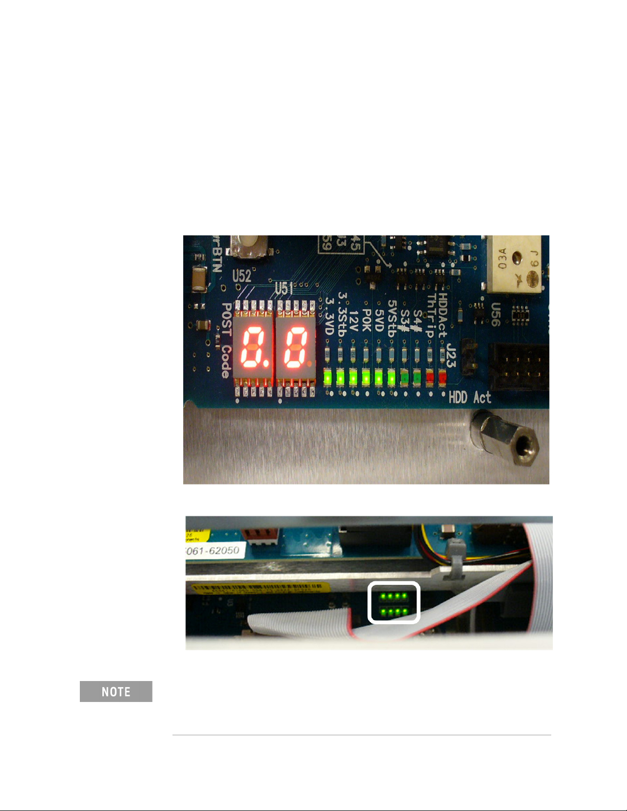
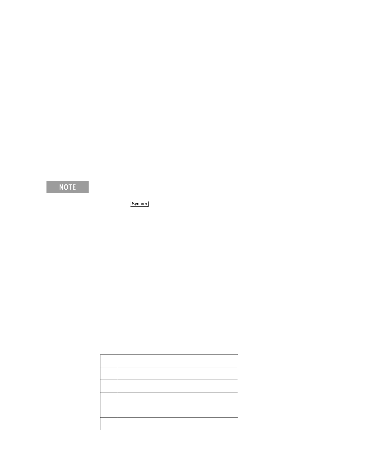
Step 1. Check fan operation and DC monitor LED
If the rear panel fan (blower) doesn't run, a failure in power supply is
assumed. Remove the E5061B outer cover and check if the following LEDs
light:
• +3.3 V and +5 V dc monitor LEDs on A50/A60 CPU Module as shown in
Figure 2-4
• LEDs on DSP module as shown in Figure 2-5
Figure 2-4 LEDs on CPU module
Figure 2-5 LEDs on DSP module
To check all the outputs of the power supply, measure the dc voltages at
the output lead connectors with a DMM. The dc output voltages and lead
color information is provided in the module cover label of the power
supply.
24 Keysight E5061B Network Analyzers
Page 25

Troubleshooting
No Display Troubleshooting
Step 2. Check system fan inside.
If the system fan on the chassis inside the E5061B don't run, problem seems
in the A51 Measurement I/F board or the flat cable between the A51
Measurement I/F board and CPU module. In this case, remove the E5061B
outer cover and make sure whether the fan run or not.
If a beep and a power shutdown occur immediately after power is turned on,
there is a possibility that the fan won’t run. The power shutdown occurs the
moment the system fan stops by any anomaly. In this case, check the fan that
doesn't run.
If the power shutdown occurs without a beep, the problem seems in the A51
Measurement I/F board or the CPU module.
Step 3. Check LED of "Num Lock" key
Press "Num Lock" key on the keyboard. If the LED in the key doesn't light as
shown in Figure 2-6, a problem seems in the CPU module.
Figure 2-6 LED of the Num Lock key
Make sure the following before replacing the CPU module.
• Whether all the connections to the A50/A60 CPU Module are normal or not.
Check if there is any disconnection or connection working loose.
Step 4. Checking with the external monitor
Connect an external VGA monitor to the VIDEO output on the E5061B rear
panel.
• If something is displayed on the external monitor, the problem is present
around the LCD. Also check the A52 Front Panel I/F board because the
ON/OFF setting of the LCD backlight is controlled by the A52 Front Panel
I/F board.
• If nothing is displayed even on the external monitor, the problem seems in
the CPU module.
Step 5. Checking flat cable
Check a flat cable between the A50/A60 CPU Module and A52 Front Panel I/F
board.
Keysight E5061B Network Analyzers 25
Page 26

2-
Troubleshooting
No Display Troubleshooting
Step 6. Check around the backlight
Check inverter board and a cable between the inverter board and A52 Front
Panel I/F board. Also check the cables between the LCD and A52 Front Panel
I/F board. If the cables are normal, check the LCD.
26 Keysight E5061B Network Analyzers
Page 27

Troubleshooting
Booting Process Troubleshooting
Booting Process Troubleshooting
Figure 2-7 represents the booting process flow in the E5061B. If the E5061B
stops in the booting process, troubleshoot using the following step-by-step
procedure.
Figure 2-7 Booting process flowchart
Keysight E5061B Network Analyzers 27
Page 28

2-
Troubleshooting
Booting Process Troubleshooting
Step 1. Splash Screen
The splash screen is displayed with Keysight logo as shown in Figure 2-8.
If the splash screen is displayed, you can assume that the A50/A60 CPU
Module is functioning correctly.
While the splash screen is displayed, if you want to run the BIOS setup
utility, push F2 key as soon as in the screen. The password to enter BIOS
setup utility is agt0nly (0 is Zero, not o).
Figure 2-8 Splash Screen
Step 2. Boot up Screen
The Boot up screen is displayed as shown in Figure 2-9.
Without choose any choice, the system will continue boot up process after 3
second.
While the Boot up screen is displayed, if you want to do system recovery,
please select “Keysight Recovery System” as soon as in the screen.
Figure 2-9 Boot up Screen
28 Keysight E5061B Network Analyzers
Page 29

Troubleshooting
Booting Process Troubleshooting
Step 3. Windows boot screens
The Windows boot screens are displayed. The Windows boot screens consists
of two screens. Each screen is displayed in the order as shown in Figure 2-10.
If the Windows boot screens are displayed, it is assumed that the HDD works.
While the Window screens are displayed, Windows operating system is
starting up.
Figure 2-10 Windows boot screens
If you encounter the following problems, try to reinstall the operating system
before replacing the HDD.
• "xxx file is missing" is displayed on DOS screen.
• The Window boot screen is not displayed after the splash screen is
displayed.
• Windows always boots up with Safe Mode.
If the E5061B was turned off without shutdown process, Microsoft
Scandisk runs while the windows boot screens are displayed. If a serious
problem is found in the scandisk, reinstall the operating system. For
details of the operating system installation, refer to Appendix B , “System
Recovery,” on page 113. If the operating system still doesn't boot up
properly after reinstallation, replace the HDD.
The operating system automatically checks the device drivers, which are
necessary to use the E5061B functions and are installed in the system
before the E5061B is shipped from Keysight factory. If the operating
system doesn't detect them, a message box is displayed. In this case,
install the device driver.
Keysight E5061B Network Analyzers 29
Page 30

2-
Troubleshooting
Booting Process Troubleshooting
Step 4. Revision and option information
The firmware revision and hardware option information along with copyright
declaration is displayed as shown in Figure 2-11. The E5061B firmware
quickly starts up just before this display appears. While the revision and
option information is displayed, the applications of various devices in the
system are initialized.
Figure 2-11 Firmware revision and option information
If the display whited out, entirely blued or appeared with a dialog box, a mass
storage problem is suspected. Try to perform the mass storage recovery
procedure.
If a message of "Will Shut Down in Five Seconds" is displayed in place of
"Initializing.." and the shutdown occurs, the DSP board fails in starting up.
The following message may be displayed before the shutdown occurs:
"Fatal Error: Failed to Initialize DSP Driver":
or "Fatal Error: Failed to Initialize DSP":
This message indicates that the DSP board doesn't work or is not properly
connected to the DSP board.
"Fatal Error: Failed to Update DSP Code":
If this happened, the DSP board failed in writing DSP program into flash
ROM when the firmware was installed first or updated to the newest
version. A problem in the DSP or A50 CPU Module is suspected.
Step 5. Measurement view
The measurement view as shown in Figure 2-12 is displayed after the system
initialization is completed without problem.
30 Keysight E5061B Network Analyzers
Page 31

Troubleshooting
Booting Process Troubleshooting
Figure 2-12 Measurement view
Step 6. Power-on self test
The power-on self test is executed once automatically before the
measurement starts. While the power-on self test is in progress, "Power on
test" is displayed at the left in the instrument status bar. If the power-on test
fails, an error message is displayed there. For more details, refer to
“Troubleshooting Using Diagnostic Test” on page 32.
Keysight E5061B Network Analyzers 31
Page 32
2-
Troubleshooting
Troubleshooting Using Diagnostic Test
Troubleshooting Using Diagnostic Test
The Keysight E5061B has an diagnostic test function to diagnose the analog
measurement section and internal dc power supply voltages. The diagnostic
test makes it possible to isolate a faulty board assembly. The following
paragraphs describe the procedure to perform the diagnostic test.
Power On Self Test
Power-on self-test always takes place once the E5061B is turned on. When a
failure is detected, a message "Power on self test failed" is displayed. The
content of the power-on self-test is the same as a part of the diagnostic test
program and includes the dc power supply voltage, source PLL synthesizer and
level controller (ALC) tests. When the self-test failed, perform the diagnostic
test to break down into the individual tests and narrow down failure
possibilities.
The following procedure can be used to restart the power-on self test as
required.
a. Press key.
b. Click Service Menu and, then, Test M enu in the softkeys.
c. Click Power On Test to restart the test. Wait until the power-on test
ends.
d. The test result (OK or Failed) is displayed in the Power On Test key.
PLL unlock
When a PLL of the frequency synthesizers is unlocked, not the "Power on self
test failed" but "Phase lock loop unlocked" message is displayed. If it occurs,
A1 Source Module may be faulty.
Contents of the diagnostic test
The diagnostic test contains 8 test groups shown in Table 2-1. Each test group
can be performed independently and verifies one of various operating
characteristics of the analog measurement section.
Table 2-1 Diagnostic test group menu
1 DC-BUS Test
2 Internal Level Monitor Test
3RF Output Level Range Test
4RF Output Level Power Sweep Test
5 Receiver Absolute Measurement Test
6 Receiver Compression Test (Option 3L5)
32 Keysight E5061B Network Analyzers
Page 33
Troubleshooting
Troubleshooting Using Diagnostic Test
Table 2-1 Diagnostic test group menu
7 Receiver IF Ranging Test
8 Gain-Phase Absolute Measurement Test
(Option 3L5)
Test equipment required for diagnostic test
Table 2-2 shows the equipment required for performing the diagnostic test.
Table 2-2 Required equipment
Required test equipment Qty Recommended model
24 inch 50 cable 1 8120-8862, 8120-1839
To Execute the Diagnostic Test
To isolate faulty board assembly in analog section, execute the diagnostic test
in accordance with the following procedure. The test procedure needs to be
performed using a mouse and an external keyboard in addition to the front
panel keys.
To perform the diagnostic test properly, the following conditions must be
met:
Environmental temperature: 23 ºC ± 5 ºC
Do not operate front panel keys, keyboard and mouse during the
diagnostic test. Changing the instrument settings while the diagnostic test
is in progress will cause incorrect test results.
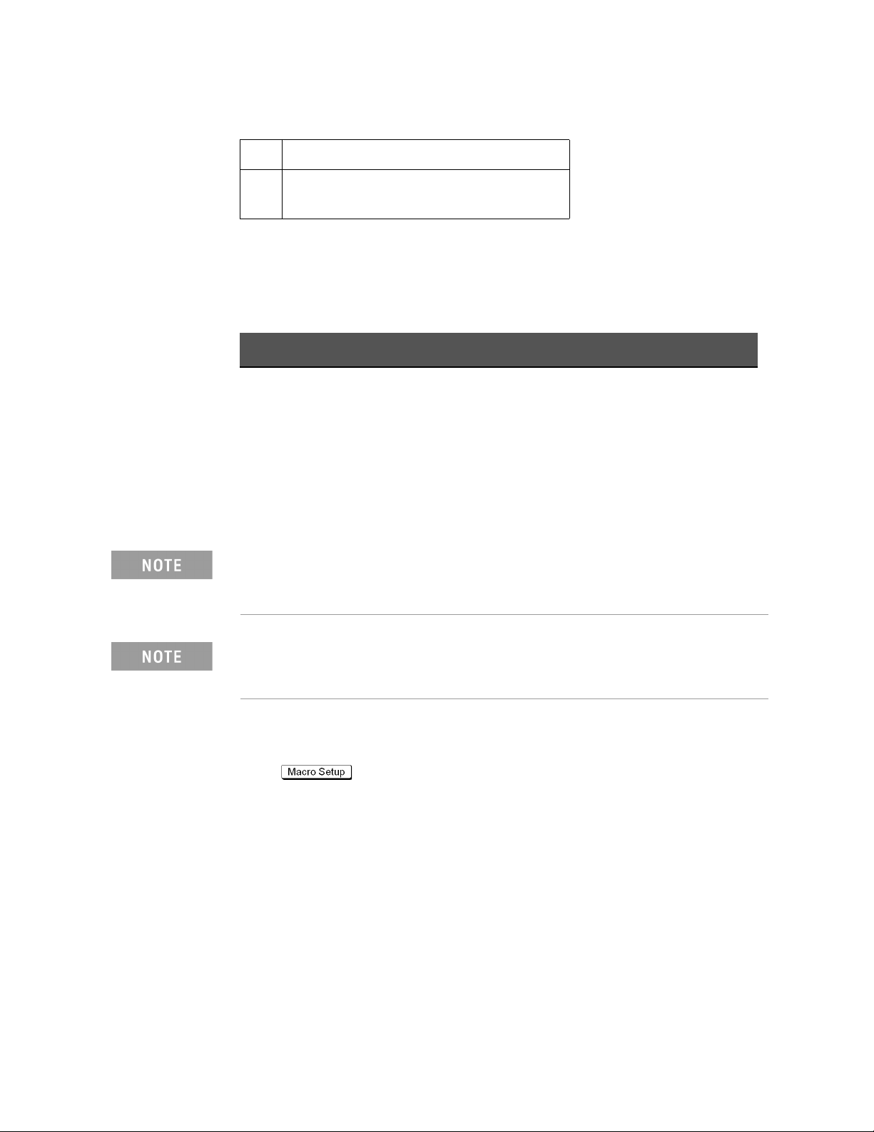
Step 1. Connect a mouse and an external keyboard to the E5061B’s rear panel
connector.
Step 2. Press key.
Step 3. Press Load Project to select Load Project function. "Open" dialog box will be
displayed as shown in Figure 2-13.
Keysight E5061B Network Analyzers 33
Page 34
2-
Troubleshooting
Troubleshooting Using Diagnostic Test
Figure 2-13 Open dialog box
Step 4. Select "User [D]" (preset state) from menu in the "Look in:" box.
Step 5. Double-click "Keysight" folder to open it and to access its menu.
Step 6. Double-click "Service" folder to open it.
Step 7. Click "DiagnosticTest. VBA" program file to select it from program menu.
Step 8. Click "Open" button to download the diagnostic test program.
Step 9. Press Select Macro to select Select Macro function.
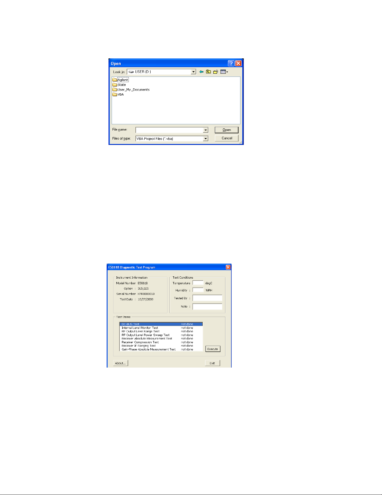
Step 10. Press Module1 main to open the Module1 main program file. "Diagnostic
Test Program" dialog box (Main Menu) will appear as shown in Figure 2-14.
Figure 2-14 Diagnostic Test dialog box
Step 11. To exit the diagnostic test, click "Exit" button.
34 Keysight E5061B Network Analyzers
Page 35
Troubleshooting
Troubleshooting Using Diagnostic Test
Program Overall
Instrument
Information The option and serial number for the E5061B, and test date
Test Conditions The test conditions, “Temperature”, “Humidity” and person
Test I tem s The following test can be selected. To execute the test you
can be entered automatically.
doing the test (“Tested by”) can be entered.
select, click “Execute” button.
•DC-BUS Test
• Internal Level Monitor Test
•RF Output Level Range Test
• RF Output Level Power SweepTest
• Receiver Absolute Measurement Test
• Receiver Compression Test (Option 3L5 only)
•Receiver IF Ranging Test
• Gain-Phase Absolute Measurement Test (option 3L5 only)
When each test is executed, the test dialog box is displayed.
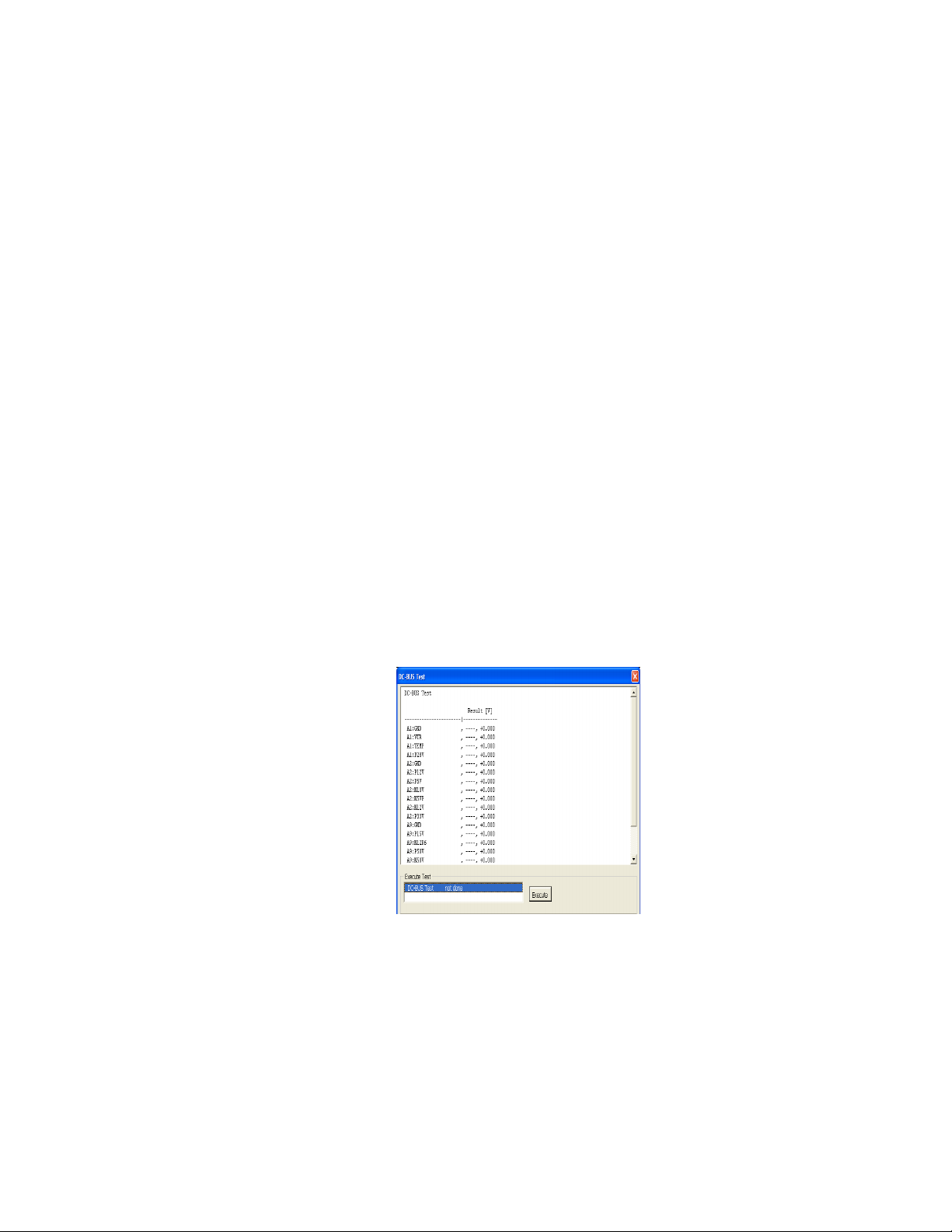
The following screen is an example of the test dialog box.
Figure 2-15 Test dialog box
To execute the test, click “Execute” button. To return the
E5061B Diagnostic test program dialog box (Main Menu),
click “Back to Main Menu”.
The test program will prompt you to connect cables or Short
termination to the E5061B. Follow the instructions as shown
below on the E5061B display for performing the test.
Keysight E5061B Network Analyzers 35
Page 36
2-
Troubleshooting
Troubleshooting Using Diagnostic Test
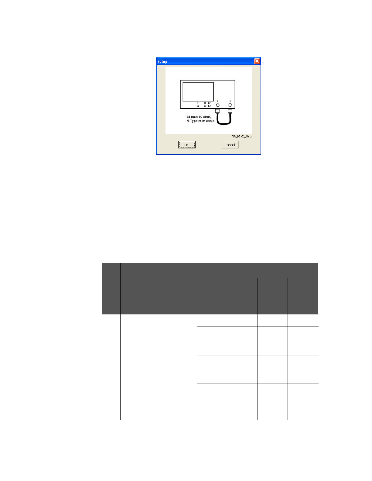
Figure 2-16 Setup dialog box
The test result file named “resultDT.txt” is created on the
drive D (D:\Keysight\Service\Log\) of the E5061B after “Exit”
button of the Main Menu is pressed. The text file can be read
and edited with a PC.
Diagnostic Test Failure Troubleshooting
Table 2-3 and Table 2-4 represents the contents of the diagnostic tests and
the relationships of failed tests to probable faulty board assemblies. If the
instrument fails the diagnostic test, replace the faulty board assembly as
shown in Table 2-3.
Table 2-3 Diagnostic tests failure troubleshooting information (Option 3L5)
Tes t
Test group Failured
No.
Tes t
1DC-BUS Test ALL ### ##
A1/A11
Source
Module
A2
Receiver
Module
Probable faulty board assembly
A1/A11
Source
Module
A2
Receiver
Module
### # #
### #
A9 LF
Source
Bias
Module
A9 LF
####
Source
Bias
Module
36 Keysight E5061B Network Analyzers
Page 37
Troubleshooting
Troubleshooting Using Diagnostic Test
Table 2-3 Diagnostic tests failure troubleshooting information (Option 3L5)
Tes t
Test group Failured
No.
Tes t
Probable faulty board assembly
A1/A11
Source
Module
A2
Receiver
Module
2 Internal Level Monitor Test ALL ## ### ##
A9 LF
Source
Bias
Module
A1/A11
### # #
Source
Module
3 RF Output Level Range Test ### # #
4 RF Output Level Power
### # #
Sweep Test
5 Receiver Absolute
#####
Measurement Test
6 Receiver Compression Test # ### #
7 Receiver IF Ranging Test # ### #
8 Gain-Phase Absolute
#####
Measurement Test
Table 2-4 Diagnostic tests failure troubleshooting information (option
115/117/135/137/215/217/235/237)
Tes t
Test group Failured Test Probable faulty board assembly
No.
A11 Source
Module
A3/A4
Receiver
Module
1DC-BUS Test ALL ###
A11 Source
### #
Module
A3/A4
###
Receiver
Module
2 Internal Level Monitor Test ALL ## ###
A11 Source
### #
Module
3 RF Output Level Range Test ### #
Keysight E5061B Network Analyzers 37
Page 38
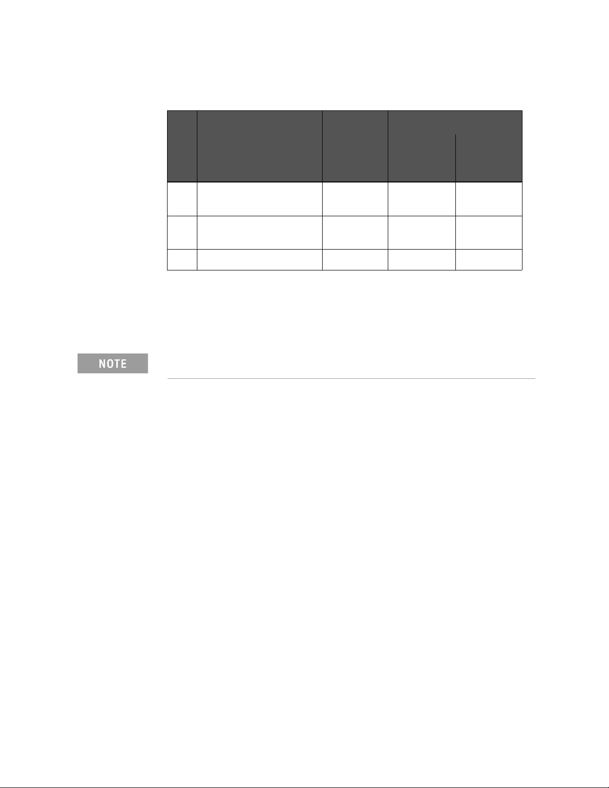
2-
Troubleshooting
Troubleshooting Using Diagnostic Test
Table 2-4 Diagnostic tests failure troubleshooting information (option
115/117/135/137/215/217/235/237)
Tes t
Test group Failured Test Probable faulty board assembly
No.
A11 Source
Module
A3/A4
Receiver
Module
4 RF Output Level Power
### #
Sweep Test
5 Receiver Absolute
####
Measurement Test
7 Receiver IF Ranging Test # ###
###: Most suspicious assembly
##: Suspicious assembly
#: Possible faulty assembly
Diagnostic tests 1 and 2 are common to the power on self test.
38 Keysight E5061B Network Analyzers
Page 39

Troubleshooting
Function Specific Troubleshooting
Function Specific Troubleshooting
If the E5061B exhibits a failure symptom that is related to a specific function or
control such as a front panel key control, display, data storage, remote control
interface, printer interface, external trigger, external keyboard or mouse,
isolate the trouble using the Function Specific Troubleshooting procedures
described below. The major functions of the E5061B and the troubleshooting
procedure for each function are shown in Table 2-5.
Table 2-5 Major functions and troubleshooting procedures
Function Description Troubleshooting
Front panel keys All the E5061B functions except for VBA and
service functions can be set and controlled via the
front panel keys.
Touch panel The E5061B equipped with option 016 has a
touch screen display that allows all the functions
in the menu bars, setup windows and dialog
boxes to be set by a touch to the screen panel.
LCD display Almost all the information including the
measurement value, setup state, result data
processing, menu bar, softkey label and others
are indicated on the 10.4-inch color LCD display.
External keyboard The external keyboard can be used for the entry of
numerical and character data when it is
connected to USB connector on front and rear
panels.
Mouse The mouse can be used to move the pointer on
the LCD display, select a function and change a
setting, when it is connected to USB connector on
front and rear panels.
Video output An external color monitor can be used to display
the same information as the E5061B LCD display,
when it is connected to the Video output
connector (24-pin D-Sub) on the rear panel.
Refer to “To Check the
Front Panel” on
page 42.
Refer to “To Check the
Touch Panel” on
page 42.
Refer to “To Check the
LCD” on page 43.
Refer to “To Check the
External Keyboard” on
page 43.
Refer to “To Check the
Mouse” on page 43.
Refer to “To Check the
Video output” on
page 44.
External trigger input The external trigger input terminal (BNC) on the
rear panel allows an external trigger source to be
used for measurement trigger.
GPIB Interface The GPIB compatibility allows the E5061B to be
operated as a talker/listener on IEEE 488
interface bus.
Handler I/O port The Handler I/O port can be used to transfer a
comparator decision output data to and perform
timing synchronization with an external handler.
Keysight E5061B Network Analyzers 39
Refer to “To Check the
External Trigger Input”
on page 44.
Refer to “To Check the
GPIB” on page 44.
Refer to in “To Execute
the Diagnostic Test” on
page 33 .
Page 40
2-
Troubleshooting
Function Specific Troubleshooting
To Check the Device Driver
Make sure first whether the E5061B device drivers are installed properly or not
by the following procedure, if a function of specific device in the E5061B
doesn't work.
Step 1. Exit from the E5061B measurement view in accordance with the procedure
described in “How to exit from the E5061B Measurement View” on page 20.
Then, Windows desktop screen is displayed.
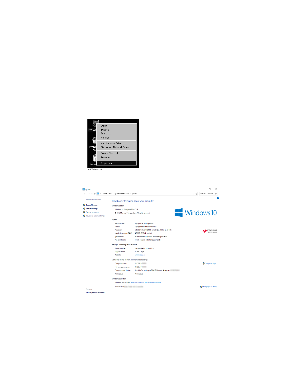
Step 2. Click "My Computer" with the right button and select "Properties" as shown
in Figure 2-17. Then, the System Properties(Figure 2-18) will appear.
Figure 2-17 Opening System Property Window
Figure 2-18 System Properties Window (General)
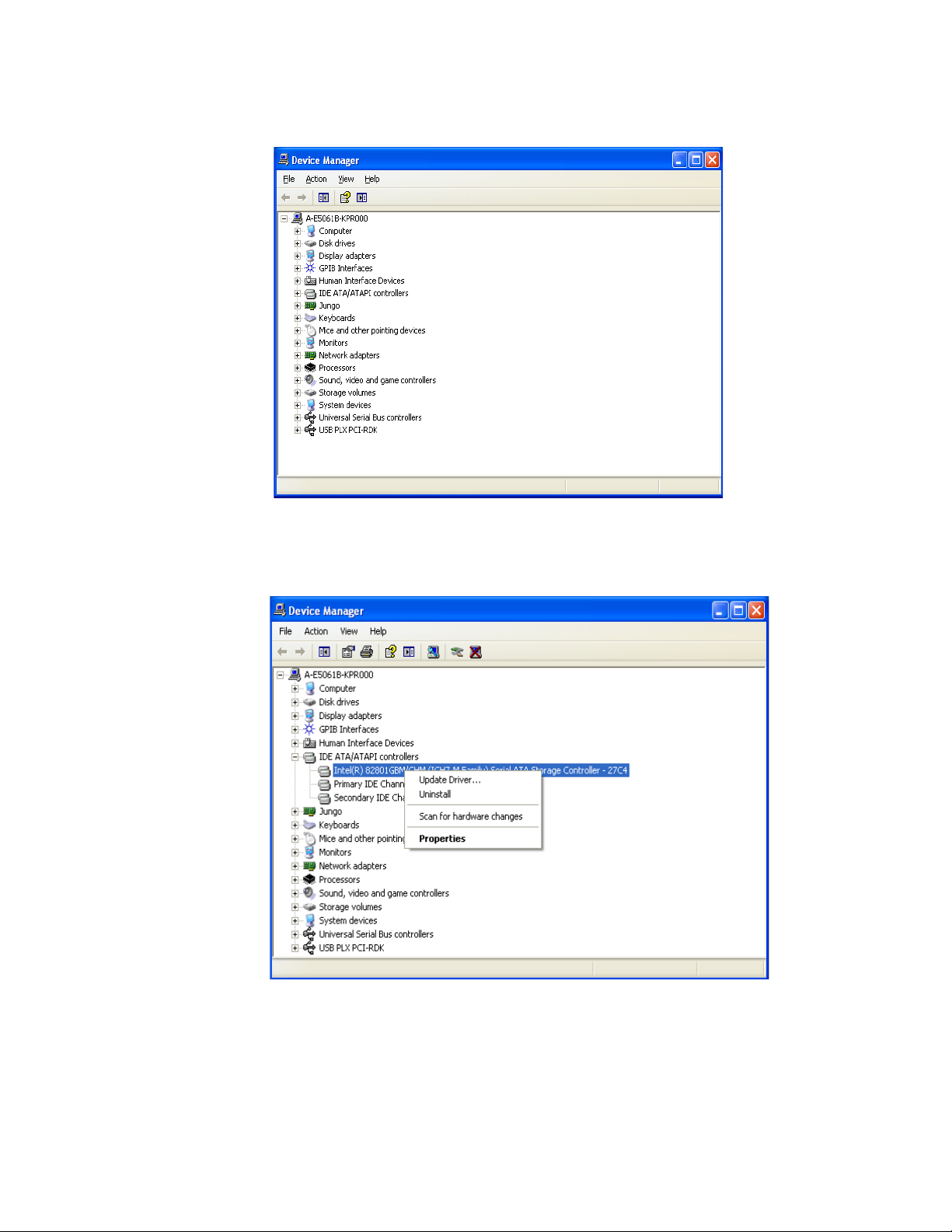
Step 3. Click Hardware tab and Device Manager button. The operating system
detects all the necessary device drivers and displays the device names as
shown in Figure 2-19.
40 Keysight E5061B Network Analyzers
Page 41
Troubleshooting
Function Specific Troubleshooting
Figure 2-19 System Properties Window (Hardware)
Click the icon with the right button and click Property to show the detail of
the status. as shown in Figure 2-20.
Figure 2-20 Opening Device Driver Property
Keysight E5061B Network Analyzers 41
Page 42

2-
Troubleshooting
Function Specific Troubleshooting
To Check the Front Panel
Procedure
Randomly press the front panel keys and rotate the knob to verify that they
work normally.
Step 1. Press key.
Step 2. Click Service Menu and, then, Test Menu in the softkeys.
Step 3. Click Front Panel in the test menu. This opens "Front Panel Test" dialog box
as shown in Figure 2-21.
Figure 2-21 Front Panel Test dialog box
Step 4. Randomly press the front panel keys. The key code along with the name of
the pressed key are displayed in the dialog box as shown in Figure 2-22. Turn
the rotary knob clockwise or counterclockwise. The dialog box indicates the
direction of the turned knob and a count of RPG output.
Figure 2-22 Key code and key name display example
Step 5. To exit the front panel test, press key three times.
• If multiple keys fail to work, a problem in A52 Front Panel I/F board or A50
CPU Module is suspected. Also check the flat cable between the A52 Front
Panel I/F board and CPU module.
• If only a specific key doesn't work, check first if the key is subsided in the
panel.
• If the rotary knob doesn't work, check the A52 Front Panel I/F board
involving the RPG.
To Check the Touch Panel
Procedure
By touching the LCD display panel, select or change the setting of a function in
the softkey menu and, then, perform the same operation with hardkeys.
42 Keysight E5061B Network Analyzers
Page 43

Troubleshooting
Function Specific Troubleshooting
• If the touch panel doesn't work correctly whereas the hardkeys function
normally, a failure seems in the touch screen controller assembly or
touch-panel LCD assembly. (The touch panel is not replaceable
independently of the LCD.)
• Check the cable between the touch screen controller and the serial
interface connector on the CPU module.
• If no problem is found in the above checks, a failure in the A50 CPU Module
is suspected.
To Check the LCD
Procedure
Step 1. Press key.
Step 2. Click Service Menu and, then, Test Menu in the softkeys menu.
Step 3. Click Display in the test menu. The whole of the LCD screen turns Red, Green,
Blue, White and Black every 2 seconds and returns to the measurement view.
If the color test screen doesn't appear correctly, perform step 4.
Step 4. Connect an external VGA monitor to the VIDEO output port on the E5061B
rear panel.
• If the monitor screen view is the same as the LCD display, the problem
seems in the CPU module.
• If only the LCD display has a problem, check the flat cable between the A52
Front Panel I/F board and CPU module.
• If the cables are normal, check the A51 LCD.
To Check the External Keyboard
Procedure
Step 1. Connect the external keyboard to the E5061B rear panel USB port.
Step 2. Turn the instrument on.
Step 3. Press key.
Step 4. Press and keys on the external keyboard, and verify that the cursor on
the menu bar moves up and down. If it doesn't work, the external keyboard or
the A50 CPU Module may be faulty.
To Check the Mouse
Procedure
Step 1. Connect the mouse to the E5061B rear panel USB port.
Keysight E5061B Network Analyzers 43
Page 44

2-
Troubleshooting
Function Specific Troubleshooting
Step 2. Turn the instrument on.
Step 3. Move the mouse and verify that the mouse pointer move smoothly. If it
doesn’t move smoothly, check first whether a foreign substance (dust, lint,
etc.) is in the track ball hole of the mouse or not.
Step 4. Verify that the mouse buttons work normally. If any button doesn't work or
the mouse pointer doesn't move, a failure in the mouse or the A50 CPU
Module is suspected.
To Check the Video output
Procedure
Step 1. Connect an external VGA color monitor to the Video output port on the
E5061B rear panel.
Step 2. Turn the external monitor on.
Step 3. Verify that the monitor screen view is the same as the display on the LCD. If
the monitor screen view is abnormal, a failure seems in the CPU module.
To Check the External Trigger Input
Procedure
Step 1. Press key to initialize the E5061B.
Step 2. Press key.
Step 3. Click Trigger Source and, then, External in the menu bar to set the trigger
mode to "External".
Step 4. Connect a BNC Short or 50 termination to the Ext Trig connector on the
rear panel and disconnect it. Thereby a measurement trigger should be
generated and a measurement result (trace) should be refreshed.
Step 5. If no trigger occurs, a failure in the DSP board is suspected.
To Check the GPIB
Procedure
Perform the E5061B performance test program. If the controller cannot detect
the E5061B, the problem seems in the CPU module.
44 Keysight E5061B Network Analyzers
Page 45

Troubleshooting
Function Specific Troubleshooting
To Check the USB
Procedure
Connect USB cable between controller PC and USB Interface port (USBTMC)
on the rear panel of E5061B. Turn the controller PC on. If the E5061B cannot
detect controller PC, the problem seems in the CPU module. Keysight I/O
Library should be installed on PC.
Keysight E5061B Network Analyzers 45
Page 46

2-
Troubleshooting
Performance Test failure Troubleshooting
Performance Test failure Troubleshooting
This section describes the adjustment and troubleshooting procedures used
when the E5061B fails the performance tests. If the performance of the
instrument is critical for the test limits and seems to be adjustable, perform
first the adjustment(s) related to the failed test. When the test result is far from
the tolerance of the test or the performance is not adjustable, isolate the faulty
assembly in accordance with the "Performance Tests failure Troubleshooting
procedure".
Recommended adjustment for Performance Test failure
Table 2-6 and Table 2-7 shows the recommended adjustments when the
performance test fails. Select the adjustment program corresponding to the
recommended adjustment and perform the adjustment.
Table 2-6 Recommended adjustment for performance test failure (Option 3L5)
First failed test Recommended adjustment
Test Num.
Oven reference
Frequency reference
1 Frequency accuracy test
2 Frequency accuracy test
(Opt. 1E5)
3 RF output level accuracy
and flatness test
4 RF output level linearity
test
5Trace noise test
6 Crosstalk & system
dynamic range test
Local gain
Mixer local leakage
Receiver absolute gain Rch
Synthesizer gain
Source output power
DC bias
Receiver IF range
Receiver port characteristics
Receiver absolute gain Tch
Receiver absolute gain LF
Source output power (LF)
DC level monitor
7 Dynamic accuracy test
8 Uncorrected system
performance test
46 Keysight E5061B Network Analyzers
Page 47

Troubleshooting
Performance Test failure Troubleshooting
Table 2-6 Recommended adjustment for performance test failure (Option 3L5)
First failed test Recommended adjustment
Test Num.
9 LF output level
accuracy& flatness test
(Opt 3L5)
10 LF output level linearity
test (Opt 3L5)
11 DC bias accuracy test
(Opt 3L5)
12 Crosstalk & noise level
test (Opt 3L5)
13 Input impedance test
(Opt 3L5)
14 Absolute amplitude
accuracy test (Opt 3L5)
15 Magnitude ratio/phase
dynamic accuracy test
(Opt 3L5)
16 Magnitude ratio/phase
frequency response test
(Opt 3L5)
Oven reference
Frequency reference
Local gain
Mixer local leakage
Receiver absolute gain Rch
Synthesizer gain
Source output power
DC bias
Receiver IF range
Receiver port characteristics
Receiver absolute gain Tch
Receiver absolute gain LF
Source output power (LF)
DC level monitor
17 Trace noise test (Opt
3L5)
18 DC measurement
accuracy test (Opt 3L5)
Keysight E5061B Network Analyzers 47
Page 48
2-
Troubleshooting
Performance Test failure Troubleshooting
Table 2-7 Recommended adjustment for performance test failure (option
115/117/135/137/215/217/235/237)
First failed test Recommended adjustment
Test Num.
1 Frequency accuracy
Oven reference
Frequency reference
Local gain
Receiver IF Range
Compression
test
2 RF output level
accuracy test
3 RF output level linearity
test
4 Crosstalk & system
dynamic range test
5 Noise Floor Test
6Trace Noise Test
7 Dynamic Accuracy Test
8Compression
9 IF linearity at 1.195GHz
10 IF linearity at LF
11 Uncorrected System
Performance test
Receiver absolute gain Rch
Synthesizer gain
Source output power
Receiver port characteristics
Receiver absolute gain Tch
Performance Test failure Troubleshooting
Note that this table lists some typical cases. There are possibilities that other
assembly may be faulty. To troubleshoot further, perform the Diagnostic Test
procedures.
48 Keysight E5061B Network Analyzers
Page 49
Troubleshooting
Performance Test failure Troubleshooting
Table 2-8 and Table 2-9 represents the relationships between the failed test
and probable faulty assembly. If the performance test failure cannot be
removed by a proper adjustment, replace the assembly shown in this table.
When Crosstalk, System dynamic range or Uncorrected system
performance test fails, check first whether the connections of the RF
semi-rigid cables between the suspicious assembly and others are tight or
loose. Also check for possible disconnection (impairment) of the cables
and connectors.
Table 2-8 Performance Test failure Troubleshooting information (Option 3L5)
First failed test Probable faulty board assembly or parts
Test Num.
A1/A11
Source
Module
A2 Receiver
Module
A9 LF
Source Bias
Module
1 Frequency accuracy test ### # #
2 RF output level accuracy and
### # #
flatness test
3 RF output level linearity test ### # #
4Trace noise test ## ### #
5 Crosstalk & system Dynamic Range
## ### #
test
6 Dynamic accuracy test # ### #
7 Uncorrected system performance
## ### #
test
8 LF output level accuracy& flatness
## ###
test (Opt 3L5)
9 LF output level linearity test (Opt
## ###
3L5)
10 DC bias accuracy test (Opt 3L5) # ###
11 Crosstalk & noise level test (Opt
#####
3L5)
12 Input impedance test (Opt 3L5) ###
13 Absolute amplitude accuracy test
#####
(Opt 3L5)
14 Magnitude ratio/phase dynamic
#####
accuracy test (Opt 3L5)
Keysight E5061B Network Analyzers 49
Page 50
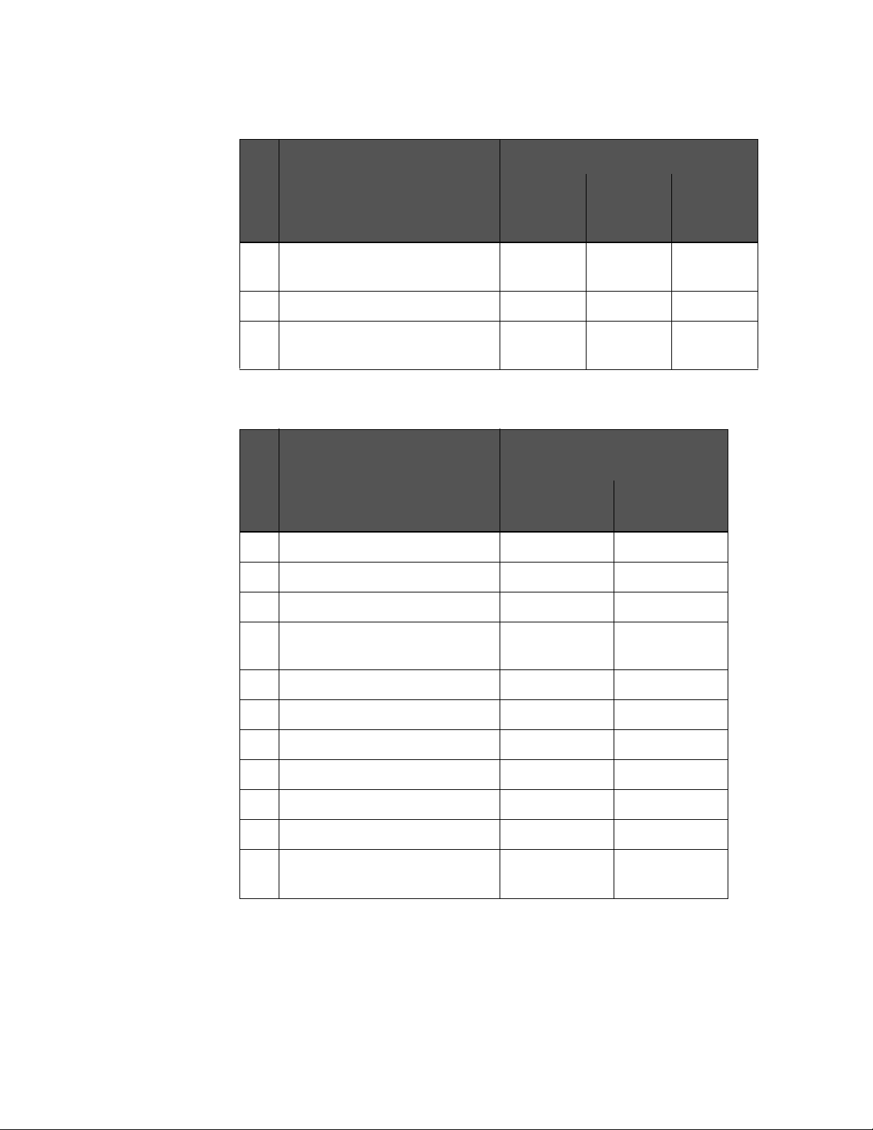
2-
Troubleshooting
Performance Test failure Troubleshooting
Table 2-8 Performance Test failure Troubleshooting information (Option 3L5)
First failed test Probable faulty board assembly or parts
Test Num.
15 Magnitude ratio/phase frequency
A1/A11
Source
Module
#####
A2 Receiver
Module
response test (Opt 3L5)
16 Trace noise test (Opt 3L5) ## ### #
17 DC measurement accuracy test
### ###
(Opt 3L5)
Table 2-9 Performance Test failure Troubleshooting information (Option
115/117/135/137/215/217/235/237)
First failed test Probable faulty board assembly or
parts
A11 Source
Test Num.
Module
A3/A4 Receiver
Module
1 Frequency accuracy test ### #
2 RF output level accuracy test ### #
A9 LF
Source Bias
Module
3 RF output level linearity test ### #
4 Crosstalk & system dynamic range
## ###
test
5 Noise Floor Test ## ###
6Trace Noise Test # ###
7 Dynamic Accuracy Test
8Compression ###
9 IF linearity at 1.195GHz ###
10 IF linearity at LF ###
11 Uncorrected System Performance
####
test
###: Most suspicious assembly
##: Suspicious assembly
#: Possible faulty assembly
50 Keysight E5061B Network Analyzers
Page 51

Keysight E5061B Network Analyzers
Service Guide
3 Replaceable Parts
This chapter contains information for ordering replacement parts for the
E5061B.
Ordering Information
To order a part in the replaceable parts lists, quote the Keysight Technologies
part number, indicate the quantity required, and address the order to the
nearest Keysight Technologies Sales Office.
To order a part not listed in the replaceable parts lists, include the instrument
model number, the description and function of the part, and the quantity of
parts required. Address the order to the nearest Keysight Technologies Sales
Office.
Direct Mail Order System
Within the USA, Keysight Technologies can supply parts through a direct mail
order system. There are several advantages to this system:
• Direct ordering and shipping from the Keysight Technologies parts center in
California, USA.
• No maximum or minimum on any mail order. (There is a minimum amount
for parts ordered through a local Keysight Technologies Sales Office when
the orders require billing and invoicing.)
• Prepaid transportation. (There is a small handling charge for each order.)
• No invoices.
In order for Keysight Technologies to provide these advantages, please send a
check or money order with each order.
Mail order forms and specific ordering information are available through your
local Keysight Technologies Sales Office. Addresses and telephone numbers
are located in a separate document shipped with the manuals.
51
Page 52

3-
Replaceable Parts
Exchange Assemblies
Exchange Assemblies
Under the rebuilt-exchange assembly program, certain factory-repaired and
tested assemblies are available on a trade-in basis. These assemblies are
offered at lower cost than a new assembly, but meet all factory specifications
required of a new assembly.
The defective assembly must be returned for credit under the terms of the
rebuilt-exchange assembly program. Any spare assembly stock desired should
be ordered using the new assembly part number.
Replaceable Parts List
The latest replaceable parts list is shown on the Keysight web site. See the
http://www.keysight.com/find/ena_support/
52 Keysight E5061B Network Analyzers
Page 53

Keysight E5061B Network Analyzers
Service Guide
4 Replacement Procedure
This chapter provides procedure for removing and replacing the major
assemblies in the E5061B.
Replacing an Assembly
The following steps show the sequence for replacing an assembly in a E5061B
Network Analyzer.
1. Identify the faulty group. Refer to Chapter 2, “Troubleshooting.”
2. Order a replacement assembly. Refer to Chapter 3, “Replaceable Parts.”
3. Replace the faulty assembly and determine what adjustments are
necessary. Refer to This chapter and Chapter 5, “Post-Repair Procedures.”
These servicing instructions are for use by qualified personnel only. To
avoid electrical shock, do not perform any servicing unless you are
qualified to do so.
The opening of covers or removal of parts is likely to expose dangerous
voltages. Disconnect the instrument from its power supply.
Many of the assemblies in this instrument are very susceptible to damage
from ESD(electrostatic discharge). Perform the following procedures only
at a static-safe workstation and wear a grounding strap.
53
Page 54
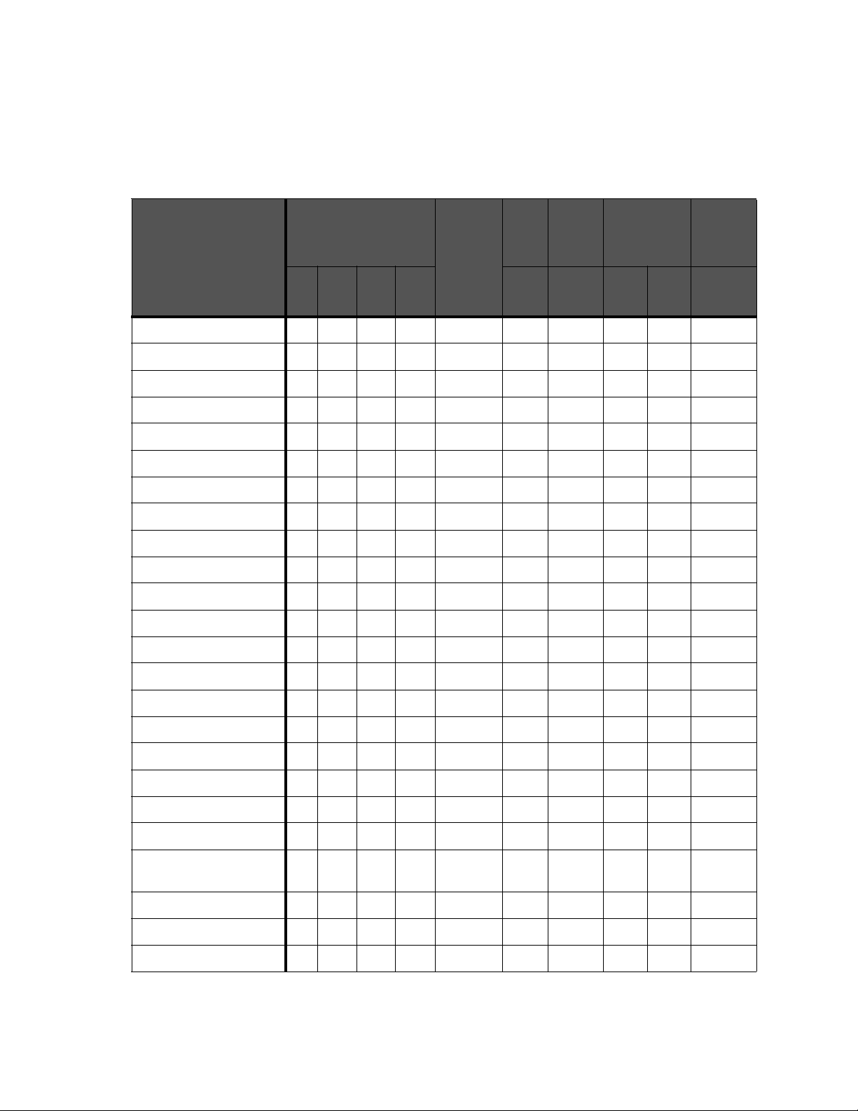
4-
Replacement Procedure
Required Tools
Required Tools
The following tools are required for repair of E5061B.
Table 4-1 Required Tools
Assembly torque screwdriver flat edge
screwdri
ver
T8 T10 T15 T20 1.5 mm5.5
Outer Cover
Front Panel
Hard Disk Assembly
Power Supply Assembly
A50 CPU Module
A60 CPU Module
24 Bit I/O Assembly
DSP Assembly
A9 LF Source Bias Module
A2 Receiver Module
A3/A4 Receiver Module
hex
key
box
torque
driver
mm
box torque
wrench
9/16
in.
5/8
in.
open
torque
wrench
5/16 in.
A1 Source Module
A11 Source Module
A10 Analog Mother Board
Ref Oven
Fan Assembly
Angle (for Fan Assembly)
Touch Screen Control Board
Inverter Board
Power Switch Assembly
A52 Front Panel Interface
Board / Key Pad
LCD Assembly
Front Frame
Handle Assembly
54 Keysight E5061B Network Analyzers
Page 55
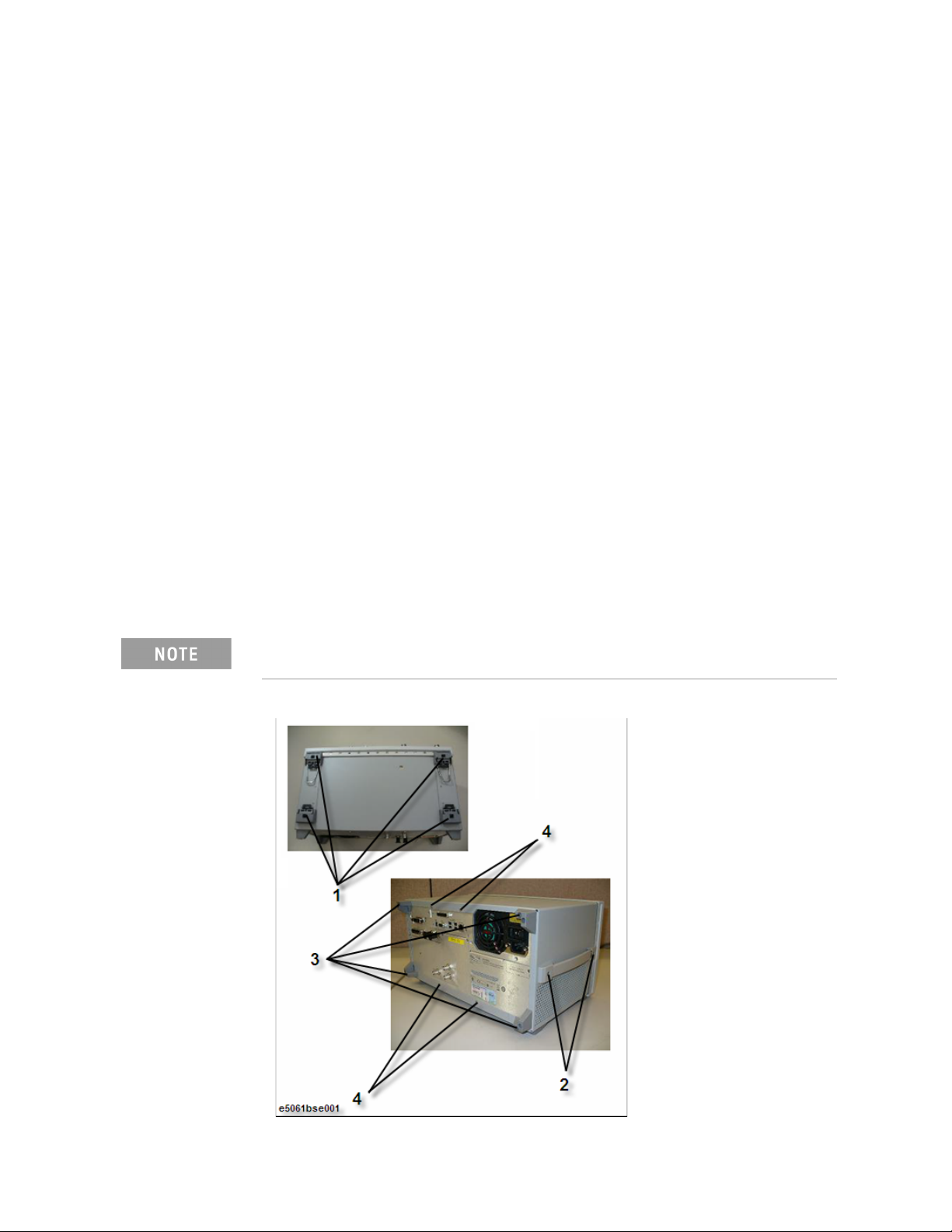
Replacement Procedure
Outer Cover Replacement
Outer Cover Replacement
Tools Required
• torque screwdriver, T20
• torque screwdriver, T15 (set to 14 in-lb)
Removal Procedure
Refer to Figure 4-1 for this procedure.
Step 1. Disconnect the power cable from the E5061B.
Step 2. Remove the four bottom feet (item 1).
Step 3. Remove the two TORX T20 screws (item 2) fastening the side strap handles.
Step 4. Remove the four TORX T15 screws (item 3) fastening the four rear foot.
Step 5. Remove the four TORX T15 screws (item 4) fastening the cover.
Step 6. Slide up the outer cover and remove it carefully.
Replacement Procedure
Step 1. Reverse the order of the removal procedure.
Set a torque to 14 in-lb for torque driver when fasten the TORX T15 screws
(item 3 and item 4).
Figure 4-1 Outer Cover Removal
Keysight E5061B Network Analyzers 55
Page 56

4-
Replacement Procedure
Front Panel Replacement
Front Panel Replacement
Tools required
• torque screwdriver T20
• torque screwdriver T15 (set to 14 in-lb)
•flat edge screwdriver
Removal Procedure
Refer to Figure 4-2 for this procedure.
Step 1. Remove the Outer Cover as described in
“Outer Cover Replacement” on page 55.
Step 2. Remove the top trim (item 1) using a flat edge driver.
Step 3. Remove the seven TORX T15 screws (item 2 ) fastening front panel.
Step 4. Gradually push the front panel assembly towards the outside.
Step 5. Release the flat cable (item 3) from the cable clamp (item 4).
Step 6. Disconnect the flat cable (item 3) from the front panel.
Replacement Procedure
Step 1. Reverse the order of the removal procedure.
Set a torque to 14 in-lb for torque driver when fasten the TORX T15 screws
(item 2).
56 Keysight E5061B Network Analyzers
Page 57
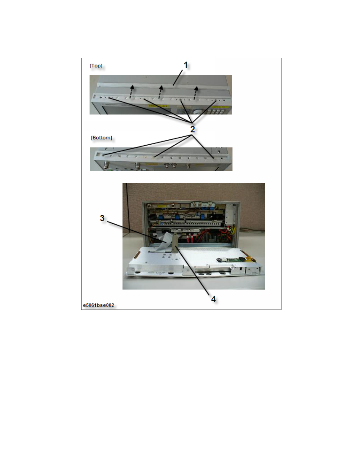
Replacement Procedure
Front Panel Replacement
Figure 4-2 Front Panel Removal
Keysight E5061B Network Analyzers 57
Page 58

4-
Replacement Procedure
Hard Disk Assembly Replacement (Option 019)
Hard Disk Assembly Replacement (Option 019)
Tools Required
• torque screwdriver, T15, and T20
• torque screwdriver, T10 (set to 4.4 in-lb, and 9 in-lb)
Removal Procedure
Refer to Figure 4-3 for this procedure.
Step 1. Remove the Outer Cover as described in “Outer Cover Replacement” on
page 55.
Step 2. Disconnect the power supply cable (item 1) from the Hard Disk Drive.
Step 3. Disconnect the S-ATA cable (item 2) from the Hard Disk Drive.
Step 4. Release the clamped cables from the clamps (item 3) on the Hard Disk
Assembly and the A50 CPU Module.
Step 5. Remove the four TORX T10 screws (item 4) fastening the Hard Disk Assembly.
Step 6. Lift the Hard Disk Assembly.
Step 7. Remove the four TORX T10 screws (item 5) fastening the Hard Disk Drive.
Replacement Procedure
Step 1. Reverse the order of the removal procedure.
Set a torque to 9 in-lb for torque driver when fasten the TORX T10 screws
(item 4).
Set a torque to 4.4 in-lb for torque driver when fasten the TORX T10
screws (item 5).
58 Keysight E5061B Network Analyzers
Page 59

Replacement Procedure
Hard Disk Assembly Replacement (Option 019)
Figure 4-3 Hard Disk Assembly Removal
Keysight E5061B Network Analyzers 59
Page 60

4-
Replacement Procedure
Hard Disk Assembly Replacement (Option 020)
Hard Disk Assembly Replacement (Option 020)
Tools Required
• torque screwdriver, T15, and T20
• torque screwdriver, T10 (set to 4.4 in-lb, and 9 in-lb)
Removal Procedure
Refer to Figure 4-3 for this procedure.
Step 1. Remove the four TORX T10 screws (item 1) fastening the Hard Disk Assembly.
Step 2. Slide out the Hard Disk Assembly.
Step 3. Disconnect the power supply cable (item 2) from the Hard Disk Drive.
Step 4. Disconnect the S-ATA cable (item 3) from the Hard Disk Drive.
Step 5. Remove the four TORX T10 screws (item 4) fastening the Hard Disk Drive.
Replacement Procedure
Step 1. Reverse the order of the removal procedure.
Set a torque to 9 in-lb for torque driver when fasten the TORX T10 screws
(item 1).
Set a torque to 4.4 in-lb for torque driver when fasten the TORX T10
screws (item 4).
60 Keysight E5061B Network Analyzers
Page 61

Replacement Procedure
Hard Disk Assembly Replacement (Option 020)
Figure 4-4 Hard Disk Assembly Removal (option 020)
Keysight E5061B Network Analyzers 61
Page 62

4-
Replacement Procedure
Power Supply Assembly Replacement
Power Supply Assembly Replacement
Tools Required
• torque screwdriver, T15, and T20
• torque screwdriver, T10 (set to 9 in-lb)
• box torque driver, 5.5 mm (set to 6 in-lb)
Removal Procedure
Refer to Figure 4-5 for this procedure.
Step 1. Remove the Outer Cover as described in “Outer Cover Replacement” on
page 55.
Step 2. Cut the three cable ties (item 1) on the guide bar.
Step 3. Remove the two TORX T10 screws (item 2) fastening the guide bar.
Step 4. Disconnect the three power supply cables (item 3) for the Hard Disk Drive,
Fan Assembly and A50 CPU Module.
Step 5. Remove the two TORX T10 screws and two washers (item 4) fastening the
chassis assembly for power supply.
Step 6. Remove the three TORX T10 screws (item 5) from the rear panel.
Step 7. Lift the power supply assembly.
Step 8. Remove the two hex screws (5.5 mm) and two washers (item 6).
Step 9. Remove the gasket (item 7), and then, re-install the two hex screws and two
washers.
Replacement Procedure
Step 1. Reverse the order of the removal procedure.
Set a torque to 9 in-lb for torque driver when fasten the TORX T10 screws
(item 4 and item 5).
Set a torque to 6 in-lb for box torque driver when fasten the 5.5 mm
screws and washers (item 6).
In step 8, the washers must not drop into the power supply.
62 Keysight E5061B Network Analyzers
Page 63

Replacement Procedure
Power Supply Assembly Replacement
Figure 4-5 Power Supply Assembly Removal
Keysight E5061B Network Analyzers 63
Page 64

4-
Replacement Procedure
A50 CPU Module Replacement
A50 CPU Module Replacement
Tools Required
• torque screwdriver, T15, and T20
• torque screwdriver, T10 (set to 9 in-lb)
Removal Procedure
Refer to Figure 4-6 for this procedure.
Step 1. Remove the Outer Cover as described in “Outer Cover Replacement” on
page 55.
Step 2. Remove the guide bar as described in “Power Supply Assembly Replacement”
on page 62.
Step 3. Disconnect the power supply cable and S-ATA cable (item 1) from the Hard
Disk Drive.
Step 4. Release the clamped cables from the three clamps (item 2).
Step 5. Disconnect the three cables (item 3) on the A50 CPU Module.
Step 6. Remove the flat cable from the clamp (item 4).
Step 7. Remove the two S-ATA cables and power supply cable (item 5) from the A50
CPU Module.
Step 8. Remove the three TORX T10 screws (item 6) fastening the Chassis Assembly
for the A50 CPU Module with Hard Disk Assembly.
Step 9. Remove the three TORX T10 screws (item 7) fastening rear panel of the
Chassis Assembly for the A50 CPU Module with Hard Disk Assembly.
Step 10. Lift the A50 CPU Module with Hard Disk Assembly.
Step 11. Remove the four TORX T10 screws (item 8) fastening the A50 CPU Module for
the Hard Disk Assembly.
Step 12. Lift the Hard Disk Assembly.
Replacement Procedure
Step 1. Reverse the order of the removal procedure.
Set a torque to 9 in-lb for torque driver when fasten the TORX T10 screws
(item 6, item 7 and item 8).
64 Keysight E5061B Network Analyzers
Page 65
Replacement Procedure
A50 CPU Module Replacement
Figure 4-6 A50 CPU Module Removal
Keysight E5061B Network Analyzers 65
Page 66

4-
Replacement Procedure
A60 CPU Module Replacement
A60 CPU Module Replacement
Tools Required
• torque screwdriver, T15, and T20
• torque screwdriver, T10 (set to 9 in-lb)
Removal Procedure
Refer to Figure 4-7 for this procedure.
Step 1. Remove the Outer Cover as described in “Outer Cover Replacement” on
page 55.
Step 2. Remove the guide bar as described in “Power Supply Assembly Replacement”
on page 62.
Step 3. Remove the Hard Drive as described in “Hard Disk Assembly Replacement
(Option 020)” on page 60.
Step 4. Disconnect the three cables (item 1) on the A60 CPU Module.
Step 5. Remove the two S-ATA cables and power supply cable (item 2) from the A60
CPU Module.
Step 6. Remove the three TORX T10 screws (item 3) fastening the Chassis Assembly
for the A60 CPU Module with Hard Disk Assembly.
Step 7. Remove the two TORX T10 screws (item 4) fastening rear panel of the Chassis
Assembly for the A60 CPU Module with Hard Disk Assembly.
Step 8. Lift the A60 CPU Module with Hard Disk Assembly.
Step 9. Remove the two TORX T10 screws (item 5) fastening the A60 CPU Module for
the Hard Disk Assembly.
Replacement Procedure
Step 1. Reverse the order of the removal procedure.
Set a torque to 9 in-lb for torque driver when fasten the TORX T10 screws
(item 6, item 7 and item 8).
66 Keysight E5061B Network Analyzers
Page 67
Replacement Procedure
A60 CPU Module Replacement
Figure 4-7 A60 CPU Module Removal
Keysight E5061B Network Analyzers 67
Page 68

4-
Replacement Procedure
24 Bit I/O Assembly Replacement
24 Bit I/O Assembly Replacement
Tools Required
• torque screwdriver, T15, and T20
• torque screwdriver, T10 (set to 9 in-lb)
•flat edge screwdriver
Removal Procedure
Refer to Figure 4-8 for this procedure.
Step 1. Remove the Outer Cover as described in “Outer Cover Replacement” on
page 55.
Step 2. Remove the Front Panel as described in “Front Panel Replacement” on
page 56.
Step 3. Disconnect the flat cable (item 1) from the 24 Bit I/O Assembly and the DSP
Assembly.
Step 4. Release the flat cable from the clamp (item 2).
Step 5. Disconnect the cable (item 3) from the 24 Bit I/O Assembly and the A50 CPU
Module.
Step 6. Release the cable from the clamp (item 4).
Step 7. Remove the two TORX T10 screws (item 5) fastening the 24 Bit I/O Assembly.
Step 8. Slide forward the 24 Bit I/O Assembly.
Replacement Procedure
Step 1. Reverse the order of the removal procedure.
Set a torque to 9 in-lb for torque driver when fasten the TORX T10 screws
(item 5).
68 Keysight E5061B Network Analyzers
Page 69
Replacement Procedure
24 Bit I/O Assembly Replacement
Figure 4-8 24 Bit I/O Assembly Removal
Keysight E5061B Network Analyzers 69
Page 70

4-
Replacement Procedure
DSP Assembly Replacement
DSP Assembly Replacement
Tools Required
• torque screwdriver, T15, and T20
• torque screwdriver, T10 (set to 9 in-lb)
• box torque wrench, 5/8 inch (set to 30.4 in-lb)
•flat edge screwdriver
Removal Procedure
Refer to Figure 4-9 for this procedure.
Step 1. Remove the Outer Cover as described in “Outer Cover Replacement” on
page 55.
Step 2. Remove the Front Panel as described in “Front Panel Replacement” on
page 56.
Step 3. Disconnect the flat cable (item 1) from the DSP Assembly.
Step 4. Disconnect the two S-ATA cable (item 2) from the DSP Assembly.
Step 5. Remove the two 5/8 inch nuts and the two washers (item 3) from the BNC
connectors.
Step 6. Remove the two TORX T10 screws (item 4) fastening the DSP Assembly.
Step 7. Slide forward the DSP Assembly.
Replacement Procedure
Step 1. Reverse the order of the removal procedure.
Set a torque 30.4 in-lb for box torque wrench when fasten the 5/8 inch
nuts and the washers (item 3).
Set a torque to 9 in-lb for torque driver when fasten the TORX T10 screws
(item 4).
70 Keysight E5061B Network Analyzers
Page 71
Replacement Procedure
DSP Assembly Replacement
Figure 4-9 DSP Assembly Removal
Keysight E5061B Network Analyzers 71
Page 72

4-
Replacement Procedure
A9 LF Source Bias Module Replacement
A9 LF Source Bias Module Replacement
Tools Required
• torque screwdriver, T15, and T20
• torque screwdriver, T10 (set to 9 in-lb)
•flat edge screwdriver
Removal Procedure
Refer to Figure 4-10 for this procedure.
Step 1. Remove the Outer Cover as described in “Outer Cover Replacement” on
page 55.
Step 2. Remove the Front Panel as described in “Front Panel Replacement” on
page 56.
Step 3. Disconnect the cable (item 1) from the A9 LF Source Bias Module.
Step 4. Disconnect the three RF cables (item 2) from the A9 LF Source Bias Module.
Step 5. Remove the two TORX T10 screws (item 3) fastening the A9 LF Source Bias
Module.
Step 6. Slide forward the A9 LF Source Bias Module.
Replacement Procedure
Step 1. Reverse the order of the removal procedure.
Set a torque to 9 in-lb for torque driver when fasten the TORX T10 screws
(item 3).
72 Keysight E5061B Network Analyzers
Page 73
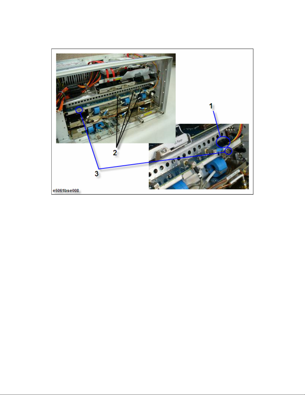
Replacement Procedure
A9 LF Source Bias Module Replacement
Figure 4-10 A9 LF Source Bias Module Removal
Keysight E5061B Network Analyzers 73
Page 74

4-
Replacement Procedure
A2 Receiver Module Replacement
A2 Receiver Module Replacement
Tools Required
• torque screwdriver, T20
• torque screwdriver, T15 (set to 14 in-lb)
• torque screwdriver, T10 (set to 9 in-lb)
• open torque wrench, 5/16 inch (set to 9.5 in-lb)
•flat edge screwdriver
Removal Procedure
Refer to Figure 4-11 for this procedure.
Step 1. Remove the Outer Cover as described in “Outer Cover Replacement” on
page 55.
Step 2. Remove the Front Panel as described in “Front Panel Replacement” on
page 56.
Step 3. Remove the three semi-rigid cables (item 1).
Step 4. Disconnect the three RF cables (item 2) from the A2 Receiver Module and the
A9 LF Source Bias Module.
Step 5. Remove the two TORX T10 screws (item 3) fastening Chassis Assembly for
the A2 Receiver Module.
Step 6. Remove the TORX T15 screw (item 4) fastening Chassis Assembly for the A2
Receiver Module.
Step 7. Slide forward the A2 Receiver Module.
Replacement Procedure
Step 1. Reverse the order of the removal procedure.
Set a torque to 9.5 in-lb for open torque wrench when fasten the
semi-rigid cables (item 1).
Set a torque to 9 in-lb for torque driver when fasten the TORX T10 screws
(item 3).
Set a torque to 14 in-lb for torque driver when fasten the TORX T15 screw
(item 4).
74 Keysight E5061B Network Analyzers
Page 75

Replacement Procedure
A2 Receiver Module Replacement
Figure 4-11 A2 Receiver Module Removal
Keysight E5061B Network Analyzers 75
Page 76

4-
Replacement Procedure
A3/A4 Receiver Module Replacement
A3/A4 Receiver Module Replacement
Tools Required
• torque screwdriver, T20
• torque screwdriver, T15 (set to 14 in-lb)
• torque screwdriver, T10 (set to 9 in-lb)
• open torque wrench, 5/16 inch (set to 9.5 in-lb)
•flat edge screwdriver
Removal Procedure
Refer to Figure 4-12 for this procedure.
Step 1. Remove the Outer Cover as described in “Outer Cover Replacement” on
page 55.
Step 2. Remove the Front Panel as described in “Front Panel Replacement” on
page 56.
Step 3. Remove the two semi-rigid cables (item 1).
Step 4. Remove the two TORX T10 screws (item 2) fastening Chassis Assembly for
the A3/A4 Receiver Module.
Step 5. Slide forward the A3/A4 Receiver Module.
Replacement Procedure
Step 1. Reverse the order of the removal procedure.
Set a torque to 9.5 in-lb for open torque wrench when fasten the
semi-rigid cables (item 1).
Set a torque to 9 in-lb for torque driver when fasten the TORX T10 screws
(item 3).
Set a torque to 14 in-lb for torque driver when fasten the TORX T15 screw
(item 4).
76 Keysight E5061B Network Analyzers
Page 77

Replacement Procedure
A3/A4 Receiver Module Replacement
Figure 4-12 A3/A4 Receiver Module Removal
Keysight E5061B Network Analyzers 77
Page 78

4-
Replacement Procedure
A1 Source Module Replacement
A1 Source Module Replacement
Tools Required
• torque screwdriver, T15 and T20
• torque screwdriver, T10 (set to 9 in-lb)
• open torque wrench, 5/16 inch
•flat edge screwdriver
Removal Procedure
Refer to Figure 4-13 for this procedure.
Step 1. Remove the Outer Cover as described in “Outer Cover Replacement” on
page 55.
Step 2. Remove the Front Panel as described in “Front Panel Replacement” on
page 56.
Step 3. Remove the A2 Receiver Module as described in “A2 Receiver Module
Replacement” on page 74.
Step 4. Disconnect the four RF cable connectors (item 1) from the A1 Source Module
and the A9 LF Source Bias Module.
Step 5. Remove the two TORX T10 screws (item 2) fastening the A1 Source Module.
Step 6. Slide forward the A1 Source Module.
Step 7. Remove the four TORX T10 screws (item 3) fastening bracket and angle for
the A1 Source Module.
Replacement Procedure
Step 1. Reverse the order of the removal procedure.
Set a torque to 9 in-lb for torque driver when fasten the TORX T10 screws
(item 2, and item 3).
78 Keysight E5061B Network Analyzers
Page 79

Replacement Procedure
A1 Source Module Replacement
Figure 4-13 A1 Source Module Removal
Keysight E5061B Network Analyzers 79
Page 80
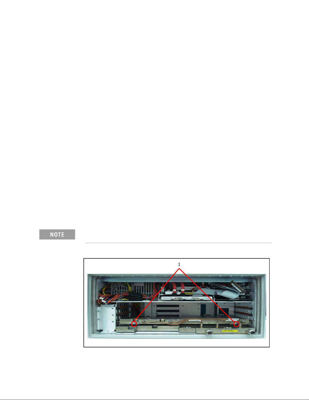
4-
Replacement Procedure
A11 Source Module Replacement
A11 Source Module Replacement
Tools Required
• torque screwdriver, T15 and T20
• torque screwdriver, T10 (set to 9 in-lb)
• open torque wrench, 5/16 inch
•flat edge screwdriver
Removal Procedure
Refer to Figure 4-13 for this procedure.
Step 1. Remove the Outer Cover as described in “Outer Cover Replacement” on
page 55.
Step 2. Remove the Front Panel as described in “Front Panel Replacement” on
page 56.
Step 3. Remove the A3/A4 Receiver Module as described in “A3/A4 Receiver Module
Replacement” on page 76.
Step 4. Remove the two TORX T10 screws (item 1) fastening the A11 Source Module.
Step 5. Slide forward the A11 Source Module.
Replacement Procedure
Step 1. Reverse the order of the removal procedure.
Set a torque to 9 in-lb for torque driver when fasten the TORX T10 screws
(item 2, and item 3).
Figure 4-14 A11 Source Module Removal
80 Keysight E5061B Network Analyzers
Page 81

Replacement Procedure
A10 Analog Mother Board Replacement
A10 Analog Mother Board Replacement
Tools Required
• torque screwdriver, T15 and T20
• torque screwdriver, T10 (set to 9 in-lb)
• box torque wrench, 9/16 inch (set to 30.4 in-lb)
•box torque wrench, 5/8 inch
• open torque wrench, 5/16 inch
•flat edge screwdriver
Removal Procedure
Refer to Figure 4-15 for this procedure.
Step 1. Remove the Outer Cover as described in “Outer Cover Replacement” on
page 55.
Step 2. Remove the Front Panel as described in “Front Panel Replacement” on
page 56.
Step 3. Remove the following assemblies.
• Hard Disk Assembly (Refer to “Hard Disk Assembly Replacement (Option
019)” on page 58.)
• A50 CPU Module (Refer to “A50 CPU Module Replacement” on page 64.)
• DSP Assembly (Refer to “DSP Assembly Replacement” on page 70.)
• A9 LF Source Bias Module (Refer to “A9 LF Source Bias Module
Replacement” on page 72.)
• A2 Receiver Module (Refer to “A2 Receiver Module Replacement” on
page 74.)
• A1 Source Module (Refer to “A1 Source Module Replacement” on
page 78.)
Step 4. Remove the three 9/16 inch nuts and the three washers (item 1) from the
BNC connectors.
Step 5. Remove the seven TORX T10 screws (item 2) fastening the rear panel.
Step 6. Remove the TORX T10 screw (item 3) fastening the small unit of the A10
Analog Mother Board.
Step 7. Disconnect the two cable connectors (item 4) from the Fan Assembly.
Step 8. Disconnect the two cable connectors (item 5) from the Power Supply
Assembly.
Step 9. Disconnect the two cable connectors (item 6) from the Ref Oven.
Step 10. Remove the eleven TORX T10 screws (item 7) fastening the A10 Analog
Mother Board.
Keysight E5061B Network Analyzers 81
Page 82

4-
Replacement Procedure
A10 Analog Mother Board Replacement
Replacement Procedure
Step 1. Reverse the order of the removal procedure.
Set a torque to 30.4 in-lb for box torque wrench when fasten the 9/16 inch
nuts and the washers (item 1).
Set a torque to 9 in-lb for torque driver when fasten the TORX T10 screws
(item 2, item 3, and item 7).
82 Keysight E5061B Network Analyzers
Page 83
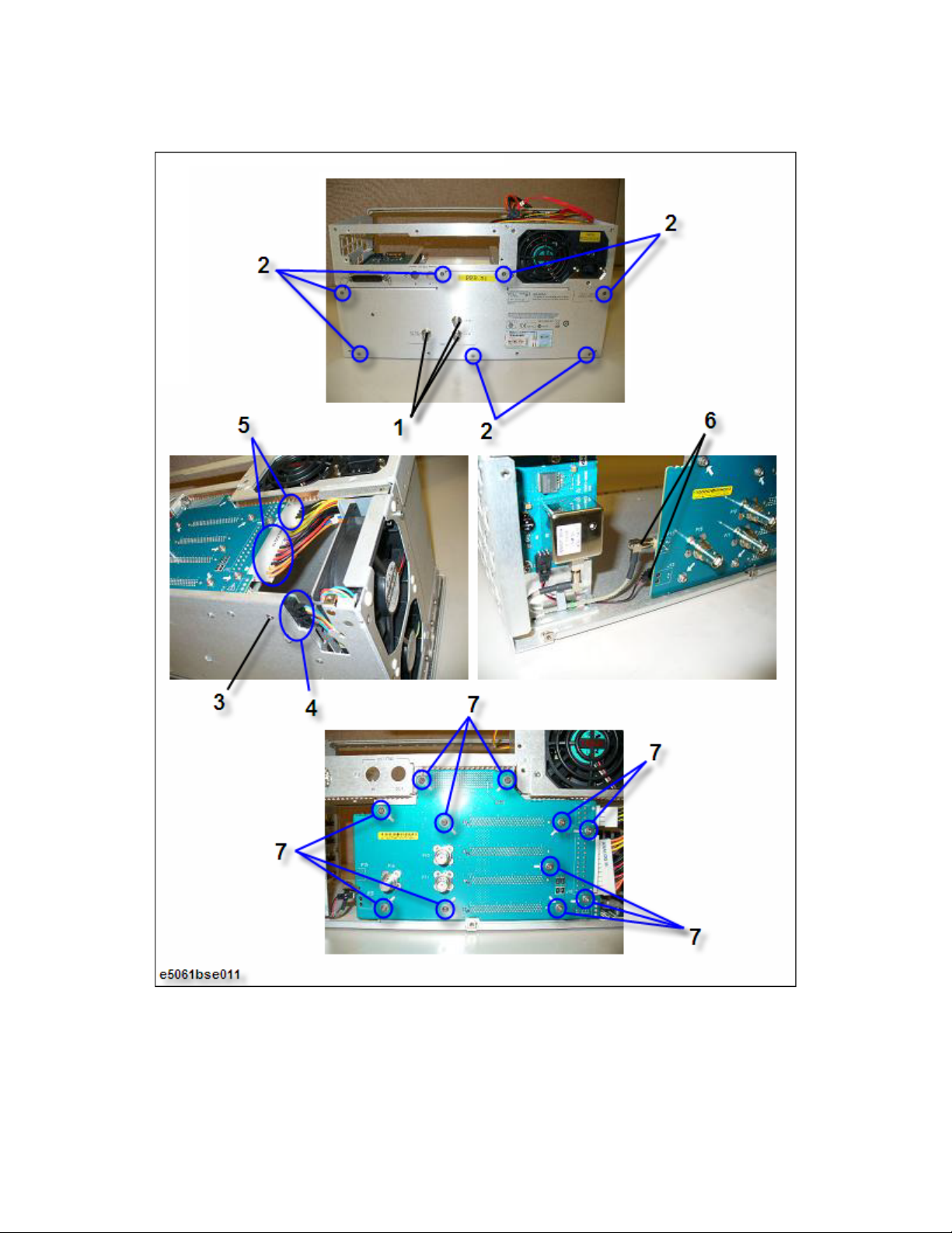
Replacement Procedure
A10 Analog Mother Board Replacement
Figure 4-15 A10 Analog Mother Board Removal
Keysight E5061B Network Analyzers 83
Page 84

4-
Replacement Procedure
Ref Oven (Opt. 1E5) Replacement
Ref Oven (Opt. 1E5) Replacement
Tools Required
• torque screwdriver, T15 and T20
• torque screwdriver, T10 (set to 9 in-lb)
• box torque wrench, 9/16 inch (set to 30.4 in-lb)
Removal Procedure
Refer to Figure 4-16 for this procedure.
Step 1. Remove the Outer Cover as described in “Outer Cover Replacement” on
page 55.
Step 2. Remove the three 9/16 inch nuts and the three washers (item 1) from the
BNC connectors.
Step 3. Remove the seven TORX T10 screws (item 2) fastening the rear panel.
Step 4. Disconnect the two cable connectors (item 3) from the Ref Oven.
Step 5. Remove the three TORX T10 screws (item 4) fastening the Ref Oven.
Step 6. Lift the Ref Oven.
Replacement Procedure
Step 1. Reverse the order of the removal procedure.
Set a torque to 30.4 in-lb for box torque wrench when fasten the 9/16 inch
nuts and the washers (item 1).
Set a torque to 9 in-lb for torque driver when fasten the TORX T10 screws
(item 2, and item 4).
84 Keysight E5061B Network Analyzers
Page 85

Replacement Procedure
Ref Oven (Opt. 1E5) Replacement
Figure 4-16 Ref Oven Removal
Keysight E5061B Network Analyzers 85
Page 86

4-
Replacement Procedure
Fan Assembly Replacement
Fan Assembly Replacement
Tools Required
• torque screwdriver, T15 and T20
• torque screwdriver, T10 (set to 9 in-lb)
• box torque wrench, 9/16 inch (set to 30.4 in-lb)
Removal Procedure
Refer to Figure 4-17 for this procedure.
Step 1. Remove the Outer Cover as described in “Outer Cover Replacement” on
page 55.
Step 2. Remove the three 9/16 inch nuts and the three washers (item 1) from the
BNC connectors.
Step 3. Remove the seven TORX T10 screws (item 2) fastening the rear panel.
Step 4. Cut the cable ties (item 3) fastening the Fan Assembly cables.
Step 5. Disconnect the two cable connectors (item 4) from the Fan Assembly.
Step 6. Remove the six TORX T10 screws (item 5) fastening the Fan Assembly.
Step 7. Lift the Fan Assembly.
Step 8. Remove the eight rivets (plastic) (item 6) fastening the Fans for the blacket.
Step 9. Peel off the tape (item 7) fastening the Fan Assembly cables.
Replacement Procedure
Step 1. Reverse the order of the removal procedure.
Set a torque to 30.4 in-lb for box torque wrench when fasten the 9/16 inch
nuts and the washers (item 1).
Set a torque to 9 in-lb for torque driver when fasten the TORX T10 screws
(item 2, and item 5).
Do not use the rivets (item 6) used once.
Pull the Fan Assembly cables before paste on tape.
86 Keysight E5061B Network Analyzers
Page 87
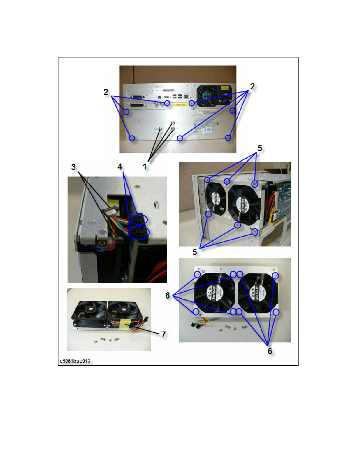
Replacement Procedure
Fan Assembly Replacement
Figure 4-17 Fan Assembly Removal
Keysight E5061B Network Analyzers 87
Page 88
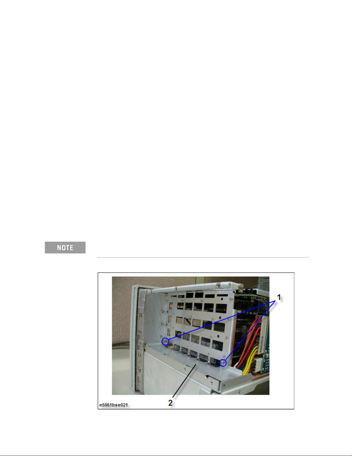
4-
Replacement Procedure
Angle (Fan Assembly) Replacement
Angle (Fan Assembly) Replacement
Tools Required
• torque screwdriver, T15 and T20
• torque screwdriver, T10 (set to 9 in-lb)
•box torque wrench, 9/16 inch
Removal Procedure
Refer to Figure 4-18 for this procedure.
Step 1. Remove the Outer Cover as described in “Outer Cover Replacement” on
page 55.
Step 2. Remove the Fan Assembly as described in “Fan Assembly Replacement” on
page 86.
Step 3. Remove the two TORX T10 screws (item 1) fastening the Angle for Fan
Assembly.
Step 4. Lift the Angle (item 2).
Replacement Procedure
Step 1. Reverse the order of the removal procedure.
Set a torque to 9 in-lb for torque driver when fasten the TORX T10 screws
(item 1).
Figure 4-18 Angle (for Fan Assembly) Removal
88 Keysight E5061B Network Analyzers
Page 89
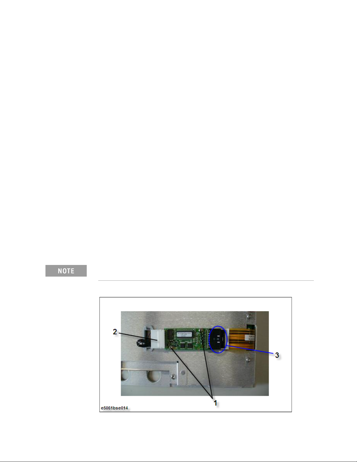
Replacement Procedure
Touch Screen Control Board Replacement
Touch Screen Control Board Replacement
Tools Required
• torque screwdriver, T15 and T20
• torque screwdriver, T8 (set to 5 in-lb)
•flat edge screwdriver
Removal Procedure
Refer to Figure 4-19 for this procedure.
Step 1. Remove the Outer Cover as described in “Outer Cover Replacement” on
page 55.
Step 2. Remove the Front Panel as described in “Front Panel Replacement” on
page 56.
Step 3. Remove the two TORX T8 screws (item 1) fastening the Touch Screen Control
Board for the front panel rear side.
Step 4. Disconnect the flat cable connector (item 2) from the A52 Front Panel
Interface Board.
Step 5. Disconnect the flat cable connector (item 3) from the LCD Assembly.
Replacement Procedure
Step 1. Reverse the order of the removal procedure.
Set a torque to 5 in-lb for torque driver when fasten the TORX T8 screws
(item 1).
Figure 4-19 Touch Screen Control Board Removal
Keysight E5061B Network Analyzers 89
Page 90

4-
Replacement Procedure
Inverter Board Replacement
Inverter Board Replacement
Tools Required
• torque screwdriver, T15 and T20
• torque screwdriver, T10 (set to 9 in-lb)
• torque screwdriver, T8 (set to 5 in-lb)
•flat edge screwdriver
Removal Procedure
Refer to Figure 4-20 for this procedure.
Step 1. Remove the Outer Cover as described in “Outer Cover Replacement” on
page 55.
Step 2. Remove the Front Panel as described in “Front Panel Replacement” on
page 56.
Step 3. Remove the Touch Screen Control Board as described in “Touch Screen
Control Board Replacement” on page 89.
Step 4. Remove the cable clamp (nylon) (item 1) from the front panel rear side cover.
Step 5. Remove the six TORX T10 screws (item 2) fastening the front panel rear side
cover.
Step 6. Lift the front panel rear side cover.
Step 7. Remove the two TORX T10 screws (item 3) fastening the Inverter Board
Assembly.
Step 8. Lift the Inverter Board Assembly, and disconnect the two cable connectors
(item 4) from the Inverter Board Assembly.
Step 9. Remove the two TORX T8 screws (item 5) fastening the Inverter Board for the
plate.
Replacement Procedure
Step 1. Reverse the order of the removal procedure.
Set a torque to 9 in-lb for torque driver when fasten the TORX T10 screws
(item 2, and Item 3).
Set a torque to 5 in-lb for torque driver when fasten the TORX T8 screws
(item 5).
90 Keysight E5061B Network Analyzers
Page 91
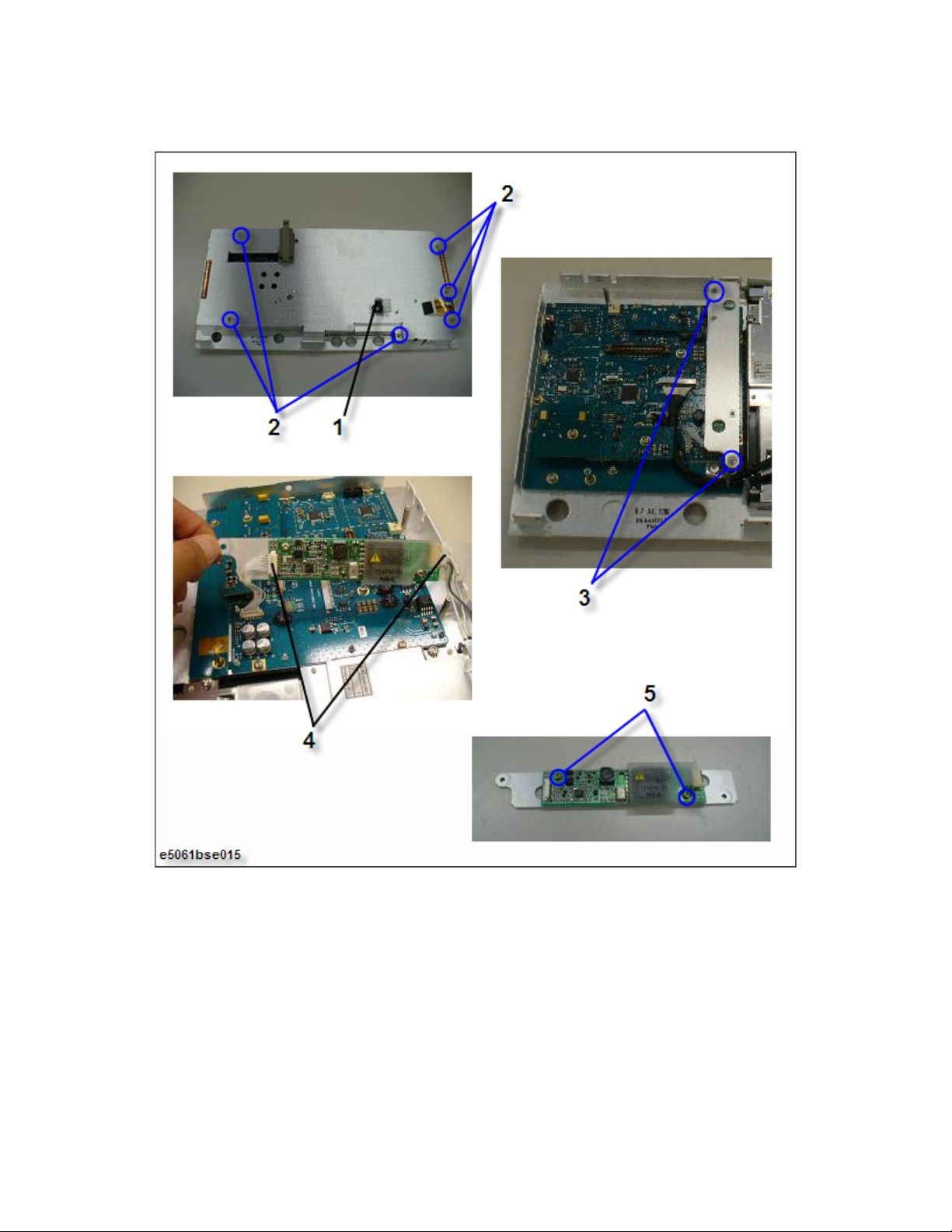
Replacement Procedure
Inverter Board Replacement
Figure 4-20 Inverter Board Removal
Keysight E5061B Network Analyzers 91
Page 92

4-
Replacement Procedure
Power Switch Assembly Replacement
Power Switch Assembly Replacement
Tools Required
• torque screwdriver, T8, T15 and T20
• torque screwdriver, T10 (set to 9 in-lb)
•flat edge screwdriver
Removal Procedure
Refer to Figure 4-21 for this procedure.
Step 1. Remove the Outer Cover as described in “Outer Cover Replacement” on
page 55.
Step 2. Remove the Front Panel as described in “Front Panel Replacement” on
page 56.
Step 3. Remove the Touch Screen Control Board as described in “Touch Screen
Control Board Replacement” on page 89.
Step 4. Remove the front panel rear side cover as described in “Inverter Board
Replacement” on page 90.
Step 5. Disconnect the connector (item 1) of cable from the A52 Front Panel Interface
Board.
Step 6. Remove the two TORX T10 screws (item 2) fastening the Power Switch
Assembly.
Step 7. Remove the parts (item 3) of the Power Switch Assembly.
Replacement Procedure
Step 1. Reverse the order of the removal procedure.
Set a torque to 9 in-lb for torque driver when fasten the TORX T10 screws
(item 2).
92 Keysight E5061B Network Analyzers
Page 93

Replacement Procedure
Power Switch Assembly Replacement
Figure 4-21 Power Switch Assembly Removal
Keysight E5061B Network Analyzers 93
Page 94

4-
Replacement Procedure
A52 Front Panel Interface Board / Key Pad Replacement
A52 Front Panel Interface Board / Key Pad Replacement
Tools Required
• torque screwdriver, T8, T15 and T20
• torque screwdriver, T10 (set to 9 in-lb)
•hex key, 1.5 mm
•flat edge screwdriver
Removal Procedure
Refer to Figure 4-22 for this procedure.
Step 1. Remove the Outer Cover as described in “Outer Cover Replacement” on
page 55.
Step 2. Remove the Front Panel as described in “Front Panel Replacement” on
page 56.
Step 3. Remove the Touch Screen Control Board as described in “Touch Screen
Control Board Replacement” on page 89.
Step 4. Remove the Inverter Board as described in “Inverter Board Replacement” on
page 90.
Step 5. Remove the rotary knob (item 1) using hex key from the front panel.
Step 6. Disconnect the three connectors (item 2) of the cables.
Step 7. Remove the TORX T10 screw and washer (item 3) fastening the cable from
the LCD Assembly.
Step 8. Remove the 13th TORX T10 screws (item 4) fastening the A52 Front Panel
Interface Board.
Step 9. Remove the Key Pad (item 5) from the A52 Front Panel Interface Board while
noting 14 pins (item 6) of rear side on Key Pad.
Step 10. Remove the USB module (item 7) of the A52 Front Panel Interface Board
carefully.
Replacement Procedure
Step 1. Reverse the order of the removal procedure.
Set a torque to 9 in-lb for torque driver when fasten the TORX T10 screws
(item 3, and item 4).
Push the USB module (item 7) sufficiently to ensure connector is fully
insert.
94 Keysight E5061B Network Analyzers
Page 95

Replacement Procedure
A52 Front Panel Interface Board / Key Pad Replacement
Figure 4-22 A52 Front Panel Interface Board / Key Pad Removal
Keysight E5061B Network Analyzers 95
Page 96

4-
Replacement Procedure
LCD Assembly Replacement
LCD Assembly Replacement
Tools Required
• torque screwdriver, T8, T10 and T20
• torque screwdriver, T15 (set to 14 in-lb)
•flat edge screwdriver
Removal Procedure
Refer to Figure 4-23 for this procedure.
Step 1. Remove the Outer Cover as described in “Outer Cover Replacement” on
page 55.
Step 2. Remove the Front Panel as described in “Front Panel Replacement” on
page 56.
Step 3. Remove the Touch Screen Control Board as described in “Touch Screen
Control Board Replacement” on page 89.
Step 4. Remove the Inverter Board as described in “Inverter Board Replacement” on
page 90.
Step 5. Disconnect the two connectors (item 1) of the cables.
Step 6. Release the clamped cable from the clamp (item 2) on the LCD Assembly.
Step 7. Remove the two cables (item 3) on the LCD Assembly.
Step 8. Remove the four TORX T15 screws (item 4) fastening the LCD Assembly.
Step 9. Lift the LCD Assembly carefully.
Replacement Procedure
Step 1. Reverse the order of the removal procedure.
Set a torque to 14 in-lb for torque driver when fasten the TORX T15 screws
(item 4).
96 Keysight E5061B Network Analyzers
Page 97
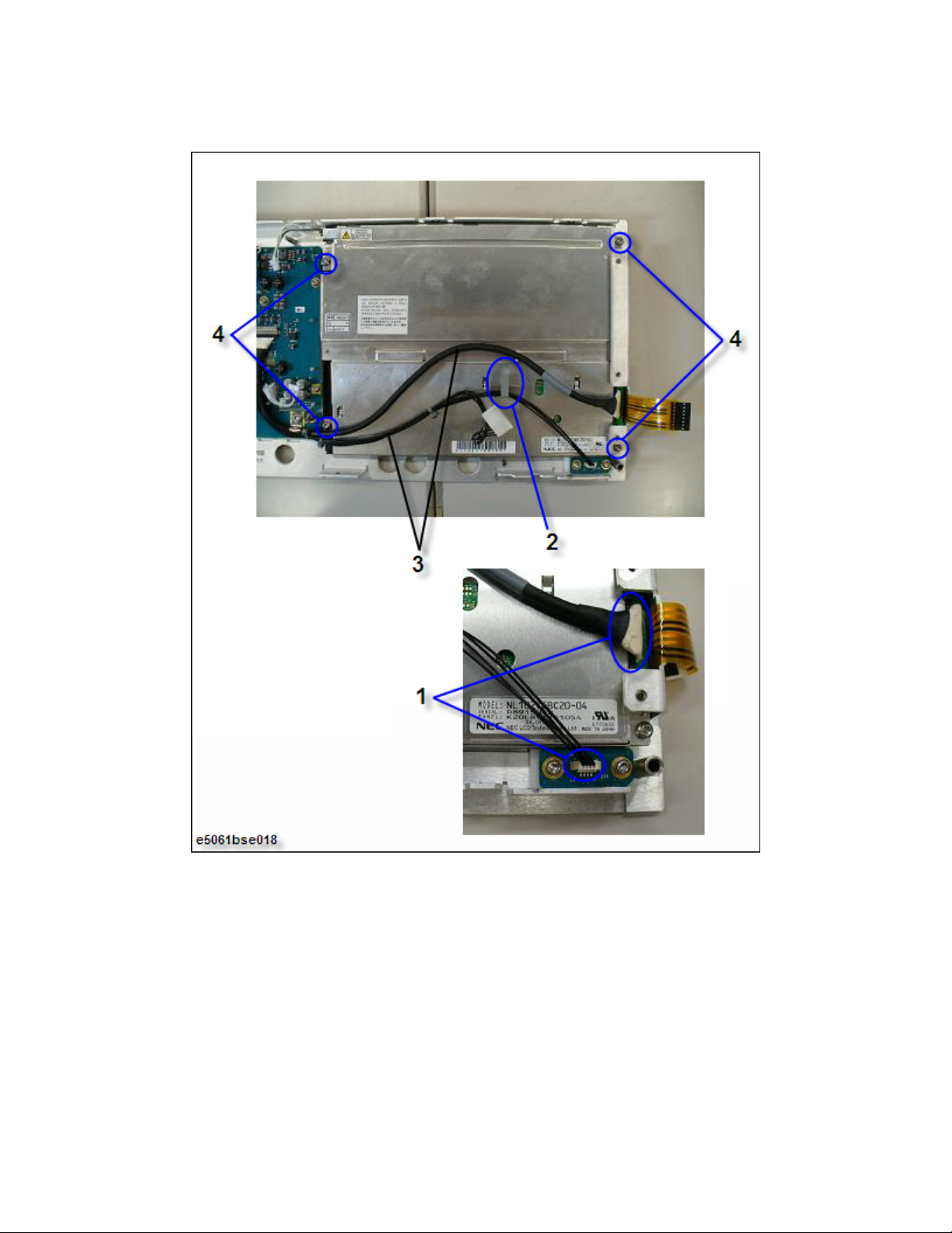
Replacement Procedure
LCD Assembly Replacement
Figure 4-23 LCDAssembly Removal
Keysight E5061B Network Analyzers 97
Page 98

4-
Replacement Procedure
Front Frame Replacement
Front Frame Replacement
Tools required
• torque screwdriver T20 (set to 21 in-lb)
• torque screwdriver T15 (set to 14 in-lb)
•flat edge screwdriver
Removal Procedure
Refer to Figure 4-24 for this procedure.
Step 1. Remove the Outer Cover as described in “Outer Cover Replacement” on
page 55.
Step 2. Remove the Front Panel as described in “Front Panel Replacement” on
page 4-56.
Step 3. Remove the four TORX T15 screws (item 1) fastening the Front Frame.
Step 4. Remove the seven TORX T20 screws (item 2) fastening the Front Frame.
Step 5. Slide forward the Front Frame.
Replacement Procedure
Step 1. Reverse the order of the removal procedure.
Set a torque to 14 in-lb for torque driver when fasten the TORX T15 screws
(item 1).
Set a torque to 21 in-lb for torque driver when fasten the TORX T20 screws
(item 2).
98 Keysight E5061B Network Analyzers
Page 99
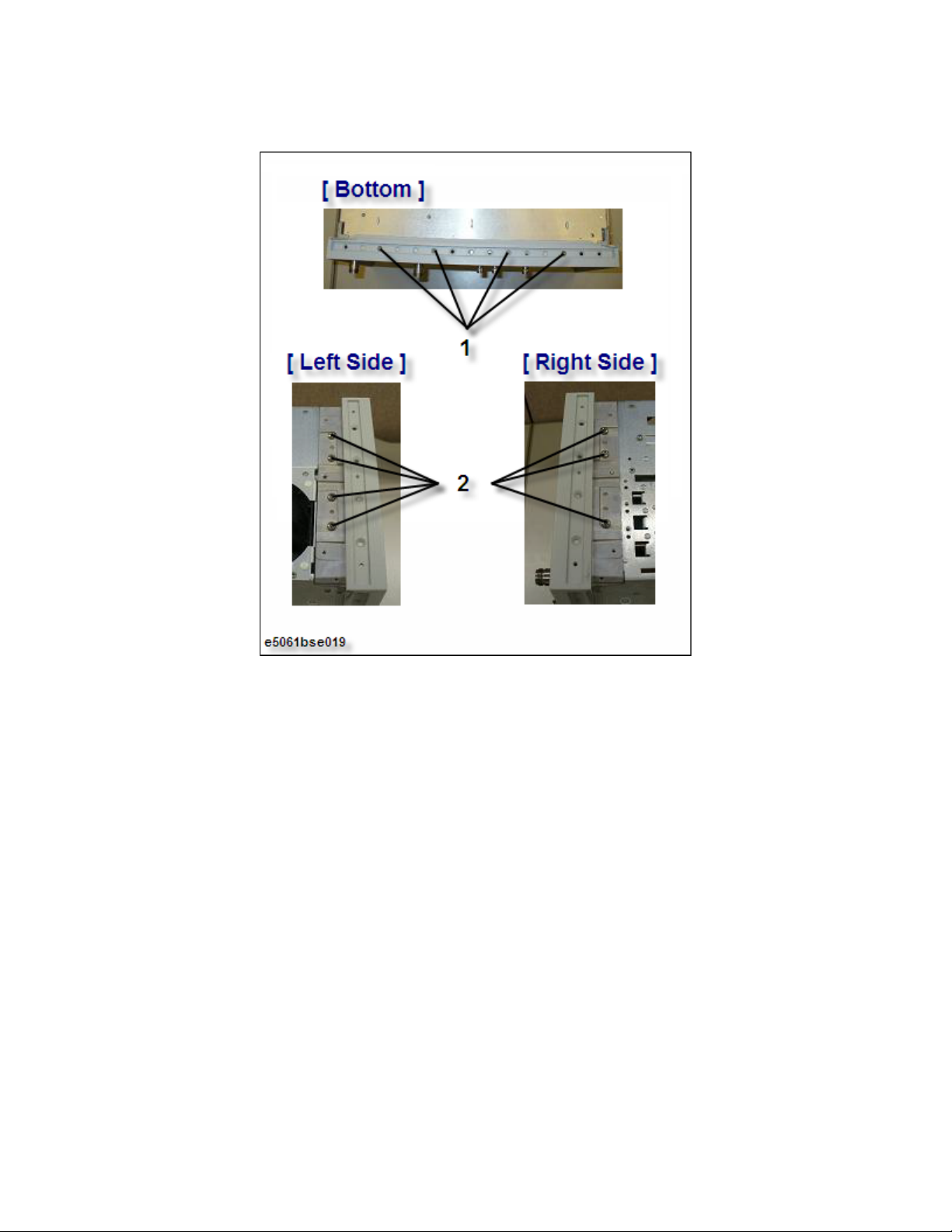
Replacement Procedure
Front Frame Replacement
Figure 4-24 Front Frame Removal
Keysight E5061B Network Analyzers 99
Page 100

4-
Replacement Procedure
Handle Assembly Replacement
Handle Assembly Replacement
Tools required
• torque screwdriver T20
Removal Procedure
Refer to Figure 4-25 for this procedure.
Step 1. Remove the four TORX T20 screws (item 1) fastening the Handle Assembly.
Step 2. Remove the end caps (both side) (item 2) from the Handle Assembly.
Step 3. Detach parts at both sides (item 3) of the Handle Assembly.
Step 4. Remove the strap cover (item 4) of the Handle Assembly.
Replacement Procedure
Step 1. Reverse the order of the removal procedure.
100 Keysight E5061B Network Analyzers
 Loading...