

Page 1

Keysight E36200 Series
Autoranging DC Power
Supplies
Service Guide
Page 2

Notices
CAUTION
WARNING
Copyright Notice
© Keysight Technologies 2019
No part of this manual may be repro-
duced in any form or by any means
(including electronic storage and
retrieval or translation into a foreign
language) without prior agreement and
written consent from Keysight Technologies as governed by United States and
international copyright laws.
Manual Part Number
E36200-90009
Edition
Edition 2, September 17, 2019
Printed in:
Printed in Malaysia
Published by:
Keysight Technologies
Bayan Lepas Free Industrial Zone,
11900 Penang, Malaysia
Technology Licenses
The hardware and/or software
described in this document are furnished under a license and may be
used or copied only in accordance with
the terms of such license.
Declaration of Conformity
Declarations of Conformity for this
product and for other Keysight products may be downloaded from the
Web. Go to http://www.keysight.com/
go/conformity. You can then search by
product number to find the latest Declaration of Conformity.
U.S. Government Rights
The Software is “commercial computer
software,” as defined by Federal Acquisition Regulation (“FAR”) 2.101. Pursuant to FAR 12.212 and 27.405-3 and
Department of Defense FAR Supplement (“DFARS”) 227.7202, the U.S.
government acquires commercial computer software under the same terms
by which the software is customarily
provided to the public. Accordingly,
Keysight provides the Software to U.S.
government customers under its standard commercial license, which is
embodied in its End User License
Agreement (EULA), a copy of which can
be found at http://www.keysight.com/
find/sweula. The license set forth in the
EULA represents the exclusive authority
by which the U.S. government may use,
modify, distribute, or disclose the Software. The EULA and the license set
forth therein, does not require or permit, among other things, that Keysight:
(1) Furnish technical information
related to commercial computer software or commercial computer software
documentation that is not customarily
provided to the public; or (2) Relinquish
to, or otherwise provide, the government rights in excess of these rights
customarily provided to the public to
use, modify, reproduce, release, perform, display, or disclose commercial
computer software or commercial computer software documentation. No
additional government requirements
beyond those set forth in the EULA
shall apply, except to the extent that
those terms, rights, or licenses are
explicitly required from all providers of
commercial computer software pursuant to the FAR and the DFARS and are
set forth specifically in writing elsewhere in the EULA. Keysight shall be
under no obligation to update, revise or
otherwise modify the Software. With
respect to any technical data as
defined by FAR 2.101, pursuant to FAR
12.211 and 27.404.2 and DFARS
227.7102, the U.S. government
acquires no greater than Limited Rights
as defined in FAR 27.401 or DFAR
227.7103-5 (c), as applicable in any
technical data.
Warranty
THE MATERIAL CONTAINED IN THIS
DOCUMENT IS PROVIDED “AS IS,”
AND IS SUBJECT TO BEING
CHANGED, WITHOUT NOTICE, IN
FUTURE EDITIONS. FURTHER, TO THE
MAXIMUM EXTENT PERMITTED BY
APPLICABLE LAW, KEYSIGHT DISCLAIMS ALL WARRANTIES, EITHER
EXPRESS OR IMPLIED, WITH REGARD
TO THIS MANUAL AND ANY INFORMATION CONTAINED HEREIN, INCLUDING BUT NOT LIMITED TO THE
IMPLIED WARRANTIES OF MERCHANTABILITY AND FITNESS FOR A
PARTICULAR PURPOSE. KEYSIGHT
SHALL NOT BE LIABLE FOR ERRORS
OR FOR INCIDENTAL OR CONSEQUENTIAL DAMAGES IN CONNECTION
WITH THE FURNISHING, USE, OR
PERFORMANCE OF THIS DOCUMENT
OR OF ANY INFORMATION CONTAINED HEREIN. SHOULD KEYSIGHT
AND THE USER HAVE A SEPARATE
WRITTEN AGREEMENT WITH WARRANTY TERMS COVERING THE MATERIAL IN THIS DOCUMENT THAT
CONFLICT WITH THESE TERMS, THE
WARRANTY TERMS IN THE SEPARATE
AGREEMENT SHALL CONTROL.
Safety Information
A CAUTION notice denotes a hazard. It
calls attention to an operating procedure, practice, or the like that, if not
correctly performed or adhered to,
could result in damage to the product
or loss of important data. Do not proceed beyond a CAUTION notice until
the indicated conditions are fully
understood and met.
A WARNING notice denotes a hazard. It
calls attention to an operating procedure, practice, or the like that, if not
correctly performed or adhered to,
could result in personal injury or death.
Do not proceed beyond a WARNING
notice until the indicated conditions are
fully understood and met.
2 Keysight E36200 Series Service Guide
Page 3

Safety Symbols
The following symbols on the instrument and in the documentation indicate
precautions which must be taken to maintain safe operation of the instrument.
Caution, risk of danger (refer to accompanying text for the specific Warning or
Caution information)
Caution, risk of electric shock
Protective earth (ground) terminal
Earth (ground) terminal
Frame or chassis (ground) terminal
Standby supply, the instrument is not completely disconnected from AC mains
when the switch is off
Direct current (DC)
Alternating current (AC)
Plus, positive polarity
Minus, negative polarity
Keysight E36200 Series Service Guide 3
Page 4

Safety Considerations
WARNING
Read the information below before using this instrument.
The following general safety precautions must be observed during all phases of
operation, service, and repair of this instrument. Failure to comply with these
precautions or with specific warnings elsewhere in this manual violates safety
standards for design, manufacture, and intended use of the instrument. Keysight
Technologies assumes no liability for the customer’s failure to comply with these
requirements.
– BEFORE APPLYING POWER
Verify that the correct fuse is installed. See “Fuse Information” in the
E36200 Series User’s Guide for additional details. Ensure the mains
supply voltage fluctuation do not exceed ±10% of the nominal supply
voltage.
– GROUND THE INSTRUMENT
This product is a Safety Class I instrument (provided with a protective
earth terminal). To minimize shock hazard, the instrument chassis and
cabinet must be connected to an electrical ground. The instrument must
be connected to the AC power supply mains through a three-conductor
power cable, with the third wire firmly connected to an electrical ground
(safety ground) at the power outlet. Any interruption of the protective
(grounding) conductor or disconnection of the protective earth terminal
will cause a potential shock hazard that could result in personal injury. If
the instrument is to be energized via an external autotransformer for
voltage reduction, be certain that the autotransformer common terminal
is connected to the neutral (earthed pole) of the AC power lines (supply
mains).
– DO NOT OPERATE IN AN EXPLOSIVE ATMOSPHERE OR WET
ENVIRONMENTS
Do not operate the device around flammable gases or fumes, vapor, or
wet environments.
4 Keysight E36200 Series Service Guide
Page 5

WARNING
– DO NOT OPERATE DAMAGED OR DEFECTIVE INSTRUMENTS
Instruments that appear damaged or defective should be made
inoperative and secured against unintended operation until they can be
repaired by qualified service personnel.
– DO NOT SUBSTITUTE PARTS OR MODIFY INSTRUMENT
Because of the danger of introducing additional hazards, do not install
substitute parts or perform any unauthorized modification to the
instrument. Return the instrument to a Keysight Technologies Sales and
Service Office for service and repair to ensure that safety features are
maintained. To contact Keysight for sales and technical support, refer to
the support links on the following Keysight website: www.keysight.com/
find/assist (worldwide contact information for repair and service).
– USE THE POWER CORD PROVIDED
Use the device with the power cord provided with the shipment.
– USE THE DEVICE AS SPECIFIED
If the device is used in a manner not specified by manufacturer, the
device protection may be impaired.
– DO NOT BLOCK VENTILATION HOLES
Keysight E36200 Series Service Guide 5
Do not block any of the ventilation holes of the device.
– OBSERVE ALL DEVICE MARKINGS BEFORE CONNECTING TO DEVICE
Observe all markings on the device before connecting any wiring to the
device.
– TURN DEVICE OFF BEFORE CONNECTING TO OUTPUT TERMINALS
Turn off the device power before connecting to the output terminals.
– ENSURE COVER IS SECURED IN PLACE
Do not operate the device with the cover removed or loosened.
Page 6

WARNING
– TURN DEVICE OFF AND REMOVE ALL CONNECTIONS BEFORE
CAUTION
NOTE
INSTALLING THE GPIB INTERFACE
Turn off the power and remove all connections, including the power cord,
from the instrument prior installation of the GPIB interface.
– ENSURE PROPER AWG CABLE IS USED
Use a cable with the correct voltage and AWG rating based on the
intended setup when operating the E36200A Series autoranging DC
power supplies.
– DO NOT TOUCH CABLES DURING OPERATION
Do not touch the cable while the instrument output is operational to
prevent electric shock hazard and burn hazard.
CLEAN WITH SLIGHTLY DAMPENED CLOTH
Clean the outside of the instrument with a soft, lint-free, slightly dampened
cloth. Do not use detergent, volatile liquids, or chemical solvents.
CONNECT USB CABLE WITH FERRITE CORE
Connect a USB cable with a ferrite core to the rear panel USB port of the
instrument for better performance.
6 Keysight E36200 Series Service Guide
Page 7

Environmental Conditions
The E36200 Series is designed for indoor use and in an area with low
condensation. The table below shows the general environmental requirements for
this instrument.
Environmental condition Requirement
Temperature
Humidity
Altitude Up to 2000 m
Pollution degree 2
Regulatory Information
Operating condition
– 0 °C to 40 °C
Storage condition
– –20 °C to 70 °C
Operating condition
– Up to 80% RH at 40 °C (non-condensing)
Storage condition
– Up to 90% RH at 65 °C (non-condensing)
The E36200 Series complies with the following safety and Electromagnetic
Compatibility (EMC) compliances:
– Low Voltage Directive 2014/35/EU
– EMC Directive 2014/30/EU
Keysight E36200 Series Service Guide 7
Page 8

Regulatory Markings
The RCM mark is a registered trademark of the Australian Communications and
Media Authority.
The CE mark is a registered trademark of the European Community. This CE
mark shows that the product complies with all the relevant European Legal
Directives.
ICES/NMB-001 indicates that this ISM device complies with the Canadian
ICES-001. Cet appareil ISM est conforme a la norme NMB-001 du Canada.
ISM GRP.1 Class A indicates that this is an Industrial Scientific and Medical
Group 1 Class A product.
This symbol is a South Korean Class A EMC Declaration. This is a Class A
instrument suitable for professional use and in electromagnetic environment
outside of the home.
The CSA mark is a registered trademark of the Canadian
Standards Association.
This symbol indicates the time period during which no hazardous or toxic
substance elements are expected to leak or deteriorate during normal use. Forty
years is the expected useful life of the product.
This instrument complies with the WEEE Directive marking requirement. This
affixed product label indicates that you must not discard this electrical or
electronic product in domestic household waste.
8 Keysight E36200 Series Service Guide
Page 9

Waste Electrical and Electronic Equipment (WEEE) Directive
This instrument complies with the WEEE Directive marking requirement. This
affixed product label indicates that you must not discard this electrical or
electronic product in domestic household waste.
Product category:
With reference to the equipment types in the WEEE directive Annex 1, this
instrument is classified as a “Monitoring and Control Instrument” product.
The affixed product label is as shown below.
Do not dispose in domestic household waste.
To return this unwanted instrument, contact your nearest Keysight Service Center,
or visit http://about.keysight.com/en/companyinfo/environment/takeback.shtml
for more information.
Sales and Technical Support
To contact Keysight for sales and technical support, refer to the support links on
the following Keysight websites:
– www.keysight.com/find/e36200
(product-specific information and support, software and
documentation updates)
– www.keysight.com/find/assist
(worldwide contact information for repair and service)
Keysight E36200 Series Service Guide 9
Page 10

THIS PAGE HAS BEEN INTENTIONALLY LEFT BLANK.
10 Keysight E36200 Series Service Guide
Page 11

Table of Contents
Safety Symbols . . . . . . . . . . . . . . . . . . . . . . . . . . . . . . . . . . . . . . . . . . . . .3
Safety Considerations . . . . . . . . . . . . . . . . . . . . . . . . . . . . . . . . . . . . . . . .4
Environmental Conditions . . . . . . . . . . . . . . . . . . . . . . . . . . . . . . . . . . . .7
Regulatory Information . . . . . . . . . . . . . . . . . . . . . . . . . . . . . . . . . . . . . . .7
Regulatory Markings . . . . . . . . . . . . . . . . . . . . . . . . . . . . . . . . . . . . . . . . .8
Waste Electrical and Electronic Equipment (WEEE) Directive . . . . . . . .9
Product category: . . . . . . . . . . . . . . . . . . . . . . . . . . . . . . . . . . . . . . . .9
Sales and Technical Support . . . . . . . . . . . . . . . . . . . . . . . . . . . . . . . . . .9
1 Service and Maintenance
Specifications and Characteristics . . . . . . . . . . . . . . . . . . . . . . . . . . . . .14
General Information . . . . . . . . . . . . . . . . . . . . . . . . . . . . . . . . . . . . . . . . 14
Types of service available . . . . . . . . . . . . . . . . . . . . . . . . . . . . . . . . .14
Obtaining repair service (worldwide) . . . . . . . . . . . . . . . . . . . . . . . . .14
Repackaging for shipment . . . . . . . . . . . . . . . . . . . . . . . . . . . . . . . . .14
Cleaning and handling . . . . . . . . . . . . . . . . . . . . . . . . . . . . . . . . . . . .15
Troubleshooting . . . . . . . . . . . . . . . . . . . . . . . . . . . . . . . . . . . . . . . . . . .16
Self-Test Procedures . . . . . . . . . . . . . . . . . . . . . . . . . . . . . . . . . . . . . . .16
Replacing the Fuse . . . . . . . . . . . . . . . . . . . . . . . . . . . . . . . . . . . . . . . . .16
User Replaceable Parts . . . . . . . . . . . . . . . . . . . . . . . . . . . . . . . . . . . . .17
Battery Replacement . . . . . . . . . . . . . . . . . . . . . . . . . . . . . . . . . . . . . . .17
Replacing the battery . . . . . . . . . . . . . . . . . . . . . . . . . . . . . . . . . . . . 18
Disassembly . . . . . . . . . . . . . . . . . . . . . . . . . . . . . . . . . . . . . . . . . . . . . .20
Tools required . . . . . . . . . . . . . . . . . . . . . . . . . . . . . . . . . . . . . . . . . .20
Removing/Installing the optional GPIB interface . . . . . . . . . . . . . . .20
Replacing the front panel binding post . . . . . . . . . . . . . . . . . . . . . . .21
2 Verification and Adjustments
Performance Verification . . . . . . . . . . . . . . . . . . . . . . . . . . . . . . . . . . . .54
Recommended test equipment . . . . . . . . . . . . . . . . . . . . . . . . . . . . .54
Keysight E36200 Series Service Guide 11
Page 12

Test considerations . . . . . . . . . . . . . . . . . . . . . . . . . . . . . . . . . . . . . . 55
Measurement techniques . . . . . . . . . . . . . . . . . . . . . . . . . . . . . . . . . 56
Constant Voltage (CV) verification . . . . . . . . . . . . . . . . . . . . . . . . . . 58
CV load and line regulation . . . . . . . . . . . . . . . . . . . . . . . . . . . . . . . . 59
Low range current verification . . . . . . . . . . . . . . . . . . . . . . . . . . . . . 67
Constant Current (CC) verification . . . . . . . . . . . . . . . . . . . . . . . . . . 69
Test Record Forms . . . . . . . . . . . . . . . . . . . . . . . . . . . . . . . . . . . . . . . . . 74
Calibration Adjustment Procedures . . . . . . . . . . . . . . . . . . . . . . . . . . . . 82
Closed-case electronic calibration . . . . . . . . . . . . . . . . . . . . . . . . . . 82
Calibration interval . . . . . . . . . . . . . . . . . . . . . . . . . . . . . . . . . . . . . . 82
Calibration adjustment process . . . . . . . . . . . . . . . . . . . . . . . . . . . . 82
Calibration security . . . . . . . . . . . . . . . . . . . . . . . . . . . . . . . . . . . . . . 83
Calibration count . . . . . . . . . . . . . . . . . . . . . . . . . . . . . . . . . . . . . . . . 84
Calibration message . . . . . . . . . . . . . . . . . . . . . . . . . . . . . . . . . . . . . 85
Saving calibration data . . . . . . . . . . . . . . . . . . . . . . . . . . . . . . . . . . . 85
Calibration auto save . . . . . . . . . . . . . . . . . . . . . . . . . . . . . . . . . . . . 85
Calibration procedure . . . . . . . . . . . . . . . . . . . . . . . . . . . . . . . . . . . . 86
Save the calibration data . . . . . . . . . . . . . . . . . . . . . . . . . . . . . . . . . 88
12 Keysight E36200 Series Service Guide
Page 13

Keysight E36200 Series Autoranging DC Power Supplies
Service Guide
1 Service and Maintenance
Specifications and Characteristics 14
General Information 14
Troubleshooting 16
Self-Test Procedures 16
Replacing the Fuse 16
User Replaceable Parts 17
Battery Replacement 17
Disassembly 20
This chapter provides the specifications and service information on cleaning,
troubleshooting, repair, and replaceable parts of the E36200 Series autoranging
DC power supplies. This chapter also explains how to assemble and disassemble
the E36200 Series autoranging DC power supplies.
13
Page 14

1 Service and Maintenance
NOTE
Specifications and Characteristics
For the specifications and characteristics of the E36200 Series autoranging DC
power supplies, refer to its datasheet at http://literature.cdn.keysight.com/
litweb/pd f/5992-3747EN.pdf.
General Information
Types of service available
If your instrument fails during the warranty period, Keysight Technologies will
repair or replace it under the terms of your warranty. After your warranty expires,
Keysight offers repair services at competitive prices. You also have the option to
purchase a service contract that extends the coverage after the standard warranty
expires.
Obtaining repair service (worldwide)
To obtain service for your instrument, contact your nearest Keysight Technologies
Service Center. They will arrange to have your unit repaired or replaced, and can
provide warranty or repair–cost information where applicable. Ask the Keysight
Technologies Service Center for shipping instructions, including what
components to ship. Keysight recommends that you retain the original shipping
carton for return shipments.
Repackaging for shipment
Ensure the following to ship the unit to Keysight for service or repair:
– Attach a tag to the unit identifying the owner and indicating the required
service or repair. Include the model number and full serial number.
– Place the unit in its original container with appropriate packaging material.
– Secure the container with strong tape or metal bands.
14 Keysight E36200 Series Service Guide
Page 15

– If the original shipping container is unavailable, use a container that will ensure
at least 10 cm (4 in.) of compressible packaging material around the entire
instrument. Use static-free packaging materials.
Keysight suggests that you always insure your shipments.
Cleaning and handling
Cleaning
To prevent electrical shock, disconnect the instrument from AC mains power and
disconnect all test leads before cleaning. Clean the outside of the instrument
using a soft, lint-free, cloth slightly dampened with water.
– Do not use detergent or solvents.
– Do not attempt to clean internally.
If required, contact a Keysight Technologies Sales and Service office to arrange
for proper cleaning to ensure that safety features and performance are
maintained.
Electrostatic Discharge (ESD) precautions
Service and Maintenance 1
Almost all electrical components can be damaged by electrostatic discharge
(ESD) during handling. Component damage can occur at electrostatic discharge
voltages as low as 50 V.
The following guidelines will help prevent ESD damage during service operations:
– Disassemble instruments only in a static-free work area.
– Use a conductive work area to reduce static charges.
– Use a conductive wrist strap to reduce static charge accumulation.
– Minimize handling.
– Keep replacement parts in original static-free packaging.
– Remove all plastic, foam, vinyl, paper, and other static-generating materials
from the immediate work area.
Keysight E36200 Series Service Guide 15
Page 16

1 Service and Maintenance
Troubleshooting
Before troubleshooting or repairing the instrument, make sure the failure is in the
instrument rather than any external connections. Also make sure that the
instrument was accurately calibrated within the last year (see “Calibration
Adjustment Procedures” on page 82 and “Calibration interval” on page 82 for
details).
Perform the following verifications if the unit is inoperative:
– Verify that the ac power cord is connected to the power supply.
– Verify that the front-panel power switch is depressed.
Self-Test Procedures
A power-on self-test occurs automatically when you turn on the power supply.
This limited test assures you that the power supply is operational.
Refer to the E36200 Series User’s Guide for more information on how to run a
complete self-test of the power supply (Chapter 2, “General Operating
Information” > Utilities Menu - Test/Setup > Self-Test).
Replacing the Fuse
The fuse is located within the power supply's fuse-holder assembly on the rear
panel. Refer to the E36200 Series User’s Guide for more information on how to
replace a faulty or blown fuse (Chapter 1, “Product Information” > Fuse
Information).
16 Keysight E36200 Series Service Guide
Page 17

User Replaceable Parts
WARNING
You can find the instrument support part list from the Keysight's Test &
Measurement Parts Catalog at http://www.keysight.com/find/parts.
Battery Replacement
SHOCKHAZARD
Only qualified, service-trained personnel who are aware of the hazards
involved should remove instrument covers. Always d isconnect the power
cable and any external circuits before removing the instrument cover.Some
circuits are active and have power for a short time even when the power
switch is turned off.
The internal battery powers the real-time clock. The primary function of the clock
it to provide a time stamp for the internal file system. If the battery fails, the clock
and time stamp function will not be available. No other instrument functions are
affected.
Under normal use at room temperature, the lithium battery has a life expectancy
between seven and ten years. Note that battery life will be reduced if the
instrument is stored for a prolonged period at temperatures above 40 degrees
Celsius.
Service and Maintenance 1
Keysight E36200 Series Service Guide 17
The battery type is CR 2032 (3V).
Page 18

1 Service and Maintenance
NOTE
Replacing the battery
You will need a flat-bladed screwdriverto perform this procedure.
1 Remove the instrument top cover.
2 The battery is located at the front PC board.
3 Use a flat-bladed screwdriver and carefully pry up on the side of the battery.
4 Install the new battery.
Make sure that the positive side (+) is facing up. Place the battery under the
small spring clips closest to the ribbon cable connector, then push down on
the opposite end of the battery to seat the battery (see red arrow below). The
top of the small spring clips should be visible after the battery is seated (see
red circle below).
5 Replace the top cover when finished.
18 Keysight E36200 Series Service Guide
Page 19

Service and Maintenance 1
NOTE
6 Reset the date and time.
Refer to the E36200 Series User’s Guide for more information on how to reset
the date and time. (Chapter 2, “General Operating Information” > Utilities
Menu - Test/Setup > User Settings > Date/Time)
Properly dispose of the old battery in accordance with local laws and
regulations.
Keysight E36200 Series Service Guide 19
Page 20

1 Service and Maintenance
WARNING
WARNING
Disassembly
Tools required
Items Torque value
PZ1 driver 9.0 in.lbs
T10 Torx driver 9.0 in.lbs
T8 Torx driver 9.0 in.lbs
1/4" nut socket 9.0 in.lbs
1/2" nut socket 3.5 in.lbs
Removing/Installing the optional GPIB interface
TURN OFF POWER AND REMOVE ALL CONNECTIONS BEFOREPROCEED
Turn off the power and remove all connections, including the power cord,
from the instrument prior installation/removal of the GPIB interface.
RETAIN GPIB COVER PLATE
After installing the GPIB interface, retain the cover plate for use in the event
that you ever remove the GPIB interface. The instrument should never be
connected to power or inputs on the output terminals without either the
GPIB interface or the cover plate securely covering the rear-panel opening.
Refer to the E36200 Series User’s Guide for more information on how to remove or
install the optional GPIB interface (Chapter 1, “Product Information” >
Installation > Installing the optional GPIB interface).
20 Keysight E36200 Series Service Guide
Page 21

Replacing the front panel binding post
WARNING
NOTE
Only qualified, service-trained personnel should remove and replace the
front panel binding post.
The GPIB interface must be removed before you proceed to remove and replace
the front panel binding post.
Disassembly procedures are model-specific. Refer to the procedures listed below
for your respective E36200 Series model.
– “For E36231A and E36232A models only” on page 22
– “For E36233A models only” on page 32
– “For E36234A models only” on page 42
Service and Maintenance 1
Keysight E36200 Series Service Guide 21
Page 22

1 Service and Maintenance
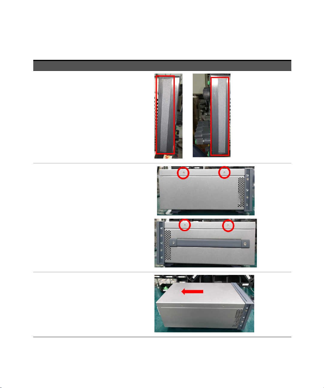
For E36231A and E36232A models only
Step Instructions Visuals
1 Remove the side trims from the front panel.
2 Remove four screws from the front panel using a
T10 driver (two screws on each side).
22 Keysight E36200 Series Service Guide
Page 23

Step Instructions Visuals
3 Remove the top panel. Slide the top panel
towards the rear and lift it up.
4 Remove the IO board thermal pad.
Service and Maintenance 1
5 Remove four Pozi screws from the front panel
using a PZ1 driver (two screws on each side).
Keysight E36200 Series Service Guide 23
Page 24

1 Service and Maintenance
Step Instructions Visuals
6 Gently pull out the front frame from the chassis.
7 Detach the mainboard connector from the IO
board.
24 Keysight E36200 Series Service Guide
Page 25

Step Instructions Visuals
8 Detach the power PSU connector from the IO
board.
9 Remove four screws from the IO board using a
T10 driver. Remove the IO board from the
chassis.
Service and Maintenance 1
Keysight E36200 Series Service Guide 25
Page 26

1 Service and Maintenance
Step Instructions Visuals
NOTE: Perform step 10 and step 12 only if you have installed the optional GPIB interface (see “Removing/Installing the optional
GPIB interface” on page 20 for more details).
10 Remove one screw from the GPIB module plate
using a T10 driver.
11 Detach the GPIB module connector from the IO
board.
12 Remove the GPIB module from the chassis.
26 Keysight E36200 Series Service Guide
Page 27

Step Instructions Visuals
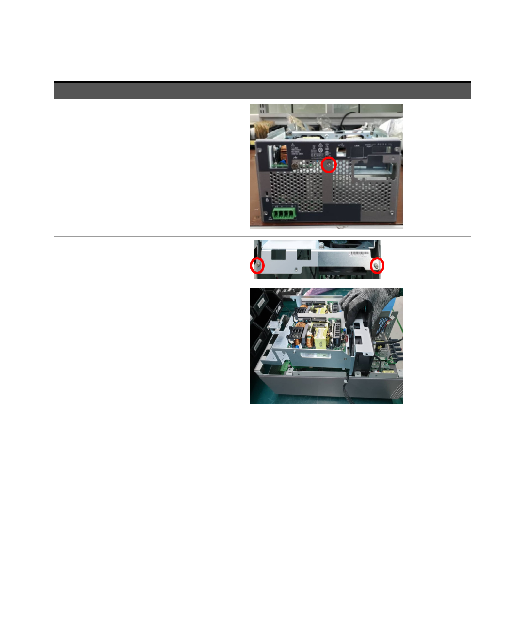
13 Detach the AC inlet connector from the PSU
module.
14 Detach the power PSU connector from the
mainboard.
Service and Maintenance 1
15 Remove one screw from the rear chassis using a
T10 bit.
Keysight E36200 Series Service Guide 27
Page 28

1 Service and Maintenance
Step Instructions Visuals
16 Remove two screws from the bracket using a T10
bit. Remove the bracket from the chassis.
17 Remove seven screws from the PCA mainboard
using a T10 bit.
28 Keysight E36200 Series Service Guide
Page 29

Step Instructions Visuals
18 Lift and remove the PCA mainboard from the
chassis.
Take caution not to bend any of the connector pins on the
IO board.
Service and Maintenance 1
Ensure that the two thermal pad are present on the PCA
mainboard before proceeding with the next step.
Keysight E36200 Series Service Guide 29
Page 30

1 Service and Maintenance
Step Instructions Visuals
19 Remove two screws from the IO board using a
T10 bit.
20 Remove three screws from the IO board using a
T10 bit. Remove the IO board from the chassis.
30 Keysight E36200 Series Service Guide
Page 31

Step Instructions Visuals
21 Unsolder the binding post assembly from the IO
board. Replace the existing binding post
assembly with a new binding post assembly.
22 Perform the steps above in reverse order to reassamble back the instrument.
Service and Maintenance 1
Keysight E36200 Series Service Guide 31
Page 32

1 Service and Maintenance
For E36233A models only
Step Instructions Visuals
1 Remove the side trims from the front panel.
2 Remove four screws from the front panel using a
T10 driver (two screws on each side).
3 Remove the top panel. Slide the top panel
towards the rear and lift it up.
32 Keysight E36200 Series Service Guide
Page 33

Step Instructions Visuals
4 Remove the IO board thermal pad.
5 Remove four Pozi screws from the front panel
using a PZ1 driver (two screws on each side).
Service and Maintenance 1
6 Detach the mainboard connectors from the IO
board.
Keysight E36200 Series Service Guide 33
Page 34

1 Service and Maintenance
Step Instructions Visuals
7 Gently pull out the front frame from the chassis.
8 Detach the power PSU connector from the IO
board.
34 Keysight E36200 Series Service Guide
Page 35

Service and Maintenance 1
Step Instructions Visuals
9 Remove four screws from the IO board using a
T10 driver. Remove the IO board from the
chassis.
NOTE: Perform step 10 and step 12 only if you have installed the optional GPIB interface (see “Removing/Installing the optional
GPIB interface” on page 20 for more details).
10 Remove one screw from the GPIB module plate
using a T10 driver.
Keysight E36200 Series Service Guide 35
Page 36

1 Service and Maintenance
Step Instructions Visuals
11 Detach the GPIB module connector from the IO
board.
12 Remove the GPIB module from the chassis.
36 Keysight E36200 Series Service Guide
Page 37

Step Instructions Visuals
13 Remove two screws from the insulator using a
T10 bit. Remove the insulator.
14 Detach the AC inlet connector from the PSU
module.
Service and Maintenance 1
15 Detach the power PSU connectors from the
mainboard.
Keysight E36200 Series Service Guide 37
Page 38

1 Service and Maintenance
Step Instructions Visuals
16 Remove one screw from the rear chassis using a
T10 bit.
17 Remove two screws from the bracket using a T10
bit. Remove the bracket from the chassis.
38 Keysight E36200 Series Service Guide
Page 39

Step Instructions Visuals
1
2
18 Remove 14 screws from the PCA mainboard
using a T10 bit.
19 Lift and remove the the two PCA mainboards
from the chassis.
Service and Maintenance 1
Keysight E36200 Series Service Guide 39
Page 40

1 Service and Maintenance
Step Instructions Visuals
Take caution not to bend any of the connector pins on the
IO board.
Ensure that the two thermal pad are present on each of
the PCA mainboards before proceeding with the next
step.
20 Remove two screws from the IO board using a
T10 bit.
40 Keysight E36200 Series Service Guide
Page 41

Step Instructions Visuals
21 Remove three screws from the IO board using a
T10 bit. Remove the IO board from the chassis.
22 Unsolder the binding post assembly from the IO
board. Remove the four screws with a T-10 bit.
Replace the existing binding post assembly with
a new binding post assembly.
Service and Maintenance 1
23 Perform the steps above in reverse order to reassamble back the instrument.
Keysight E36200 Series Service Guide 41
Page 42
1 Service and Maintenance
For E36234A models only
Step Instructions Visuals
1 Remove the side trims from the front panel.
2 Remove four screws from the front panel using a
T10 driver (two screws on each side).
3 Remove the top panel. Slide the top panel
towards the rear and lift it up.
42 Keysight E36200 Series Service Guide
Page 43

Step Instructions Visuals
4 Remove the IO board thermal pad.
5 Remove four Pozi screws from the front panel
using a PZ1 driver (two screws on each side).
Service and Maintenance 1
6 Detach the mainboard connectors from the IO
board.
Keysight E36200 Series Service Guide 43
Page 44

1 Service and Maintenance
Step Instructions Visuals
7 Gently pull out the front frame from the chassis.
8 Detach the power PSU connector from the IO
board.
44 Keysight E36200 Series Service Guide
Page 45

Service and Maintenance 1
Step Instructions Visuals
9 Remove four screws from the IO board using a
T10 driver. Remove the IO board from the
chassis.
NOTE: Perform step 10 and step 12 only if you have installed the optional GPIB interface (see “Removing/Installing the optional
GPIB interface” on page 20 for more details).
10 Remove one screw from the GPIB module plate
using a T10 driver.
Keysight E36200 Series Service Guide 45
Page 46

1 Service and Maintenance
Step Instructions Visuals
11 Detach the GPIB module connector from the IO
board.
12 Remove the GPIB module from the chassis.
46 Keysight E36200 Series Service Guide
Page 47

Step Instructions Visuals
13 Remove two screws from the insulator using a
T10 bit. Remove the insulator.
14 Detach the AC inlet connector from the PSU
module.
Service and Maintenance 1
15 Detach the power PSU connectors from the
mainboard.
Keysight E36200 Series Service Guide 47
Page 48
1 Service and Maintenance
Step Instructions Visuals
16 Remove one screw from the rear chassis using a
T10 bit.
17 Remove two screws from the bracket using a T10
bit. Remove the bracket from the chassis.
48 Keysight E36200 Series Service Guide
Page 49

Step Instructions Visuals
1
2
18 Remove 14 screws from the PCA mainboard
using a T10 bit.
19 Lift and remove the the two PCA mainboards
from the chassis.
Service and Maintenance 1
Keysight E36200 Series Service Guide 49
Page 50

1 Service and Maintenance
Step Instructions Visuals
Take caution not to bend any of the connector pins on the
IO board.
Ensure that the two thermal pad are present on each of
the PCA mainboards before proceeding with the next
step.
20 Remove two screws from the IO board using a
T10 bit.
50 Keysight E36200 Series Service Guide
Page 51

Step Instructions Visuals
21 Remove three screws from the IO board using a
T10 bit. Remove the IO board from the chassis.
Service and Maintenance 1
22 Unsolder the binding post assembly from the IO
board. Replace the existing binding post
assembly with a new binding post assembly.
23 Perform the steps above in reverse order to reassamble back the instrument.
Keysight E36200 Series Service Guide 51
Page 52

1 Service and Maintenance
THIS PAGE HAS BEEN INTENTIONALLY LEFT BLANK.
52 Keysight E36200 Series Service Guide
Page 53

Keysight E36200 Series Autoranging DC Power Supplies
Service Guide
2 Verification and
Adjustments
Performance Verification 54
Test Record Forms 74
Calibration Adjustment Procedures 82
This chapter contains the performance verification procedures, which verifies that
the E36200 Series is operating within its published specifications. This chapter
also provides information on the adjustments performed after the instrument fails
any of the performance verification tests.
53
Page 54

2 Verification and Adjustments
Performance Verification
Performance verification ensures that the instrument performs within the
specifications stated in its data sheet (http://literature.cdn.keysight.com/litweb/
pdf/5992-3747EN.pd f.)
Recommended test equipment
The test equipments recommended for the performance verification and
adjustment procedures are listed below. If the exact instrument is not available,
use the accuracy requirements shown to select substitute calibration standards.
Type Specification Recommended model
Digital multimeter
Current monitor 50 A (0.05 Ω), TC = 4 ppm/°C Guildline 9230A-50
Electronic load
Fixed load
Oscilloscope
RMS voltmeter
Differential amplifier Bandwidth: 20 MHz LeCroy 1855A or equivalent
Readout: 6 ½ digits
Basic DC accuracy: 0.0035%
150 V, 20 A minimum, with transient capability
and a slew rate of 833 kA/s or better
Wirewound resistor 1000 W, 40 Ω
E36232A and E36234A output: 18 Ω
Wirewound resistor 1000 W, 10 Ω
E36231A and E36233A output: 4.5 Ω
Wirewound resistor 2000 W, 2.5 Ω
E36232A and E36234A output: 2 Ω
Wirewound resistor 2000 W, 0.6 Ω
E36231A and E36233A output: 0.5 Ω
Sensitivity: 1 mV
Bandwid th limit: 20 MHz
Probe: 1:1 with RF tip
True RMS
Bandwid th: 10 MHz
Sensitivity: 100 μV
Keysight 34465A or equivalent
Keysight N3300A mainframe, with
N330xA modules
DSR-1000W40RJ-F-V1
DSR-1000W10RJ-F-V1
DSR-2000W2R5J-F-V1
DSR-2000WR6J-F-V1
Keysight Infiniium/6054A or
equivalent
Keysight 3458A or equivalent
54 Keysight E36200 Series Service Guide
Page 55

Verification and Adjustments 2
CAUTION
NOTE
NOTE
Type Specification Recommended model
Terminations
Variable voltage
transformer or AC
source
Resistors for low
range current
1 – 50 Ω BNC termination
2 – 50 Ω, ≥ 1/8 W resistor
Adjustable to highest rated input voltage range
Power: 500 VA
E36231/E36233A output: 300 Ω high power resistor, 5 W ARCOL HS100 300R F
E36232A/E36234A output: 1.2 kΩ power resistor, 5 W ARCOL HS75 1K2 F
N/A
Keysight 6813B or equivalent
Test considerations
– Ensure that the calibration ambient temperature is stable and between 20 °C
and 30 °C.
– Ensure ambient relative humidity is less than 80%.
– Allow a 1-hour warm-up period before verification or calibration.
– Keep cables as short as possible, consistent with the impedance requirements.
– Performance verification and calibration procedure must be performed
through rear panel output.
The tests should be performed by qualified personnel. During performance
verification tests, hazardous voltages may be present at the outputs of the
power supply.
Refer to the E36200 Series Programming Guide for more information on the SCPI
commands used in this chapter.
For E36233A and E36234A models, perform the verification test described below
for Output 1 and then repeat the test again for Output 2.
Keysight E36200 Series Service Guide 55
Page 56

2 Verification and Adjustments
Measurement techniques
Voltmeter
To ensure that the values read by the voltmeter during both the verification
procedure and the calibration procedure are not affected by the instantaneous
measurement of the AC peaks of the output current ripple, make several DC
measurements and average them.
Current-monitoring resistor
The 4-terminal current shunt is used to eliminate output current measurement
error caused by voltage drops in the load leads and connections. It has special
current-monitoring terminals inside the load connection terminals. Connect the
voltmeter directly to these current-monitoring terminals.
Electronic load
Many of the test procedures require the use of a variable load capable of
dissipating the required power. If a variable resistor is used, switches should be
used to connect, disconnect, or short the load resistor. For most tests, an
electronic load can be used. The electronic load is considerably easier to use than
load resistors, but it may not be fast enough to test transient recovery time and
may be too noisy for the noise (PARD) tests.
Fixed load resistors may be used in place of a variable load, with minor changes to
the test procedures. Also, if computer controlled test setups are used, the
relatively slow (compared to computers and system voltmeters) settling times and
slew rates of the power system may have to be taken into account. “Wait”
statements can be used in the test program if the test system is faster than the
power system.
56 Keysight E36200 Series Service Guide
Page 57

Verification and Adjustments 2
Setup for most tests
This setup is used for most tests and it requires the DMM, electronic load, and
power supply being verified. Some wire is also required for connection between
instruments. A LAN or USB cable is needed for readback data. The DMM
measures the power supply output, and the electronic load draws current from
the power supply. The accuracy of the current monitoring resistor must be 0.01%
or better, which should include any self-heating effects.
Keysight E36200 Series Service Guide 57
Page 58

2 Verification and Adjustments
Constant Voltage (CV) verification
Voltage programming and readback accuracy
These tests verify that the voltage programming and the LAN or USB readback
functions are within specifications. Note that the readback values over the remote
interface should be identical to those displayed on the front panel, but with
maximum resolution.
1 Turn off the power supply using the AC line switch.
2 Connect a DMM between the (+) and (–) terminals of the output.
3 If you are using a PC to control the power supply, connect a LAN, GPIB, or USB
cable from the power supply to the PC.
4 Turn on the power supply using the AC line switch.
Voltage programming accuracy
Step Front panel SCPI
5 Set the instrument settings as
described in Table 2-1.
6 Enable the output by pressing the
On key for the selected output.
The output status should be CV and the output current should be close to zero.
7 Record the voltage measured by the DMM in the “Test Record Forms” on
page 74 and verify whether it is within the limits calculated.
Voltage readback accuracy
Step Front panel SCPI
8 MEAS:VOLT?, (@<channel>)
VOLT 30, (@<channel>; CURR
20, (@<channel>)
This is an example for the E36231A,
20 V, 20 A output.
OUTP ON, (@<channel>)
This is an example for the E36231A,
30 V, 20 A output.
58 Keysight E36200 Series Service Guide
Page 59

Verification and Adjustments 2
9 Record the voltage returned by the SCPI command query via the Keysight
Connection Expert in the “Test Record Forms” on page 74 , and verify whether
it is within the limits calculated.
Table 2-1 Voltage programming and readback accuracy instrument settings
DUT settings Programming accuracy Readback accuracy
Model Voltage (V) Current (A) Lower limit Upper limit Lower limit Upper limit
E36231A /
E36233A
0 20 –0.004 V 0.004 V –0.004 V 0.004 V
30 20 29.987 V 30.013 V –0.013 V 0.013 V
E36232A /
E36234A
0 10 –0.008 V 0.008 V –0.008 V 0.008 V
60 10 59.974 V 60.026 V –0.026 V 0.026 V
CV load and line regulation
These tests verify that the voltage variation due to load or line variation are within
specifications.
CV load regulation
This test measures the change in output voltage resulting from a change in output
current from full load to no load.
1 Turn off the power supply using the AC line switch.
2 Connect the power supply output with a DMM and an electronic load.
3 If you are using a PC to control the power supply, connect a LAN, GPIB, or USB
cable from the power supply to the PC.
4 Turn on the power supply using the AC line switch.
5 Set the power supply settings as described in Ta ble 2- 2.
6 Enable the output.
Keysight E36200 Series Service Guide 59
Page 60

2 Verification and Adjustments
7 Operate the electronic load in constant current mode and set its current to the
value described in Table 2-2.
Check that the front panel CV annunciator of the power supply remains lit. If it
turns to CC or UNREG, adjust the load so that the output current drops slightly
until the CV annunciator lights up. Record the output voltage reading on the
DMM as V
load
.
8 Operate the electronic load in open mode (input off). Record the output
voltage reading on the DMM immediately as V
noload
.
9 Take the difference between the DMM readings in step 7 and step 8 that is the
CV load regulation (V
load
– V
. Record the calculated value in the “Test
noload)
Record Forms” on page 74. The difference of the readings during the
immediate change should be within the specification limits.
Tab le 2-2 CV load regulation instrument setting
DUT settings E-load settings Load regulation
Model Voltage (V) Current (A) Mode Current (A) Lower limit Upper limit
E36231A /
E36233A
E36232A /
E36234A
30 Max Current 6.667 –5 mV 5 mV
10 Max Current 20 –3 mV 3 mV
60 Max Current 3.333 –8 mV 8 mV
20 Max Current 10 –4 mV 4 mV
CV line regulation
This test measures the change in output voltage that results from a change in AC
line voltage from the minimum to maximum value within the line voltage
specifications.
1 Turn off the power supply using the AC line switch.
2 Connect the power supply output with a DMM and an electronic load.
3 Connect a variable AC Source or Variac to the AC input, and set to an
appropriate line voltage for the power supply configuration.
4 If you are using a PC to control the power supply, connect a LAN, GPIB, or USB
cable from the power supply to the PC.
60 Keysight E36200 Series Service Guide
Page 61

Verification and Adjustments 2
5 Turn on the power supply using the AC line switch.
6 Set the power supply settings as described in Ta ble 2- 3.
7 Enable the output.
8 Operate the electronic load in constant current mode and set its current to the
value described in Table 2-3.
Check that the front panel CV annunciator of the power supply remains lit. If it
turns to CC or UNREG, adjust the load so that the output current drops slightly
until the CV annunciator lights up.
9 Adjust the AC power source to the low line voltage limit (see Table 2-3).
Record the output reading on the DMM as V
lowline
.
10 Adjust the AC power source to the high line voltage limit (see Table 2-3).
Record the output reading on the DMM as V
highline
.
11 Take the difference between the DMM readings in step 9 and step 10 that is
the CV line regulation (V
lowline
– V
). Record the calculated value in the
highline
“Test Record Forms” on page 74. The difference of the readings during the
immediate change should be within the limit calculated from the specification.
Table 2-3 CV line regulation instrument setting
DUT settings AC source settings E-Load settings Line regulation
Model
E36231A /
E36233A
E36232A /
E36234A
Voltage
(V)
30 Max
10 Max Current 20 –3 mV 3 mV
30 Max
10 Max Current 20 –3 mV 3 mV
60 Max
20 Max Current 10 –4 mV 4 mV
60 Max
20 Max Current 10 –4 mV 4 mV
Current
(A)
Low High Mode
Current 6.667 –5 mV 5 mV
90 VAC 132 VAC
Current 6.667 –5 mV 5 mV
180 VAC 264 VAC
Current 3.333 –8 mV 8 mV
90 VAC 132 VAC
Current 3.333 –8 mV 8 mV
180 VAC 264 VAC
Current
(A)
Lower
limit
Upper
limit
Line
Voltage
100 VAC -
120 VAC
200 VAC -
240 VAC
100 VAC -
120 VAC
200 VAC -
240 VAC
Keysight E36200 Series Service Guide 61
Page 62

2 Verification and Adjustments
Transient response verification
This test measures the time for the output voltage to recover to within the
specified value following a 50% change in the load current.
1 Turn off the power supply using the AC line switch.
2 Connect an oscilloscope and electronic load between the (+) and (–) terminals
of the output to be tested as shown below.
3 If you are using a PC to control the power supply, connect a LAN, GPIB, or USB
cable from the power supply to the PC.
4 Turn on the power supply using the AC line switch.
5 Set the instrument settings as described in Ta ble 2-4.
6 Enable the output.
62 Keysight E36200 Series Service Guide
Page 63

Verification and Adjustments 2
NOTE
7 Operate the electronic load in constant current mode and set its current to the
value described in Table 2-4.
Set the transient level to ½ the maximum current. Set the transient duty cycle
to 50% and transient frequency to 1 kHz. Check that the front panel CV
annunciator of the power supply remains lit. If it turns to CC or UNREG, adjust
the maximum current load so that the output current drops slightly until the
CV annunciator lights up.
8 Adjust the oscilloscope to display transients as shown below. Note that the
pulse width (t2 – t1) of the transient at the voltage settling band, for example
15 mV for the E36234A Output 1 from the base line is no more than 50 µs.
– The oscilloscope cursors X1 and X2 represent t1 and t2.
– The oscilloscope green trace and yellow trace represent output current and
output voltage trace.
Record the measured value in the “Test Record Forms” on page 74. The
transient response specification is met when the voltage recovers within
50 µs.
Keysight E36200 Series Service Guide 63
Page 64

2 Verification and Adjustments
Tab le 2-4 Transient response verification instrument setting
DUT Setting E-Load Transient Response
Model Voltage (V) Current (A) Current (A) T-Level Lower l imit Upper limit
E36231A /
E36233A
E36232A /
E36234A
30 MAX 6.667 3.333 - 50 μs
10 MAX 20 10 - 50 μs
60 MAX 3.333 1.67 - 50 μs
20 MAX 10 5 - 50 μs
Output noise verification
Periodic and random output deviations superimpose a residual AC voltage on the
DC output. This residual voltage is specified as the rms or peak-to-peak noise in
and is specified in the product data sheet.
1 Turn off the power supply using the AC line switch.
2 Connect a fixed load, differential amplifier, and an oscilloscope (AC coupled) to
the output as shown below.
3 Turn on the power supply using the AC line switch.
64 Keysight E36200 Series Service Guide
Page 65

Verification and Adjustments 2
4 Use an appropriate load resistor (see the fixed load value in the Recommended
test equipment list) to keep the power system at the instrument setting
specified in Table 2-6.
5 As shown in the figure, use two BNC cables to connect the differential
amplifier to the (+) and (−) output terminals. Each cable should be terminated
by a 50 Ω resistor. The shields of the two BNC cables should be connected
together. Connect the differential amplifier output to the oscilloscope with a
50 Ω termination at the oscilloscope input.
6 Set the differential amplifier to multiply by ten, divide by one, and 1 MΩ input
resistance. Set the differential amplifier's positive and negative inputs to AC
coupling. Set the oscilloscope’s time base to 5 ms/div, and the vertical scale to
10 mV/div. Turn the bandwidth limit on (usually 20 or 30 MHz), and set the
sampling mode to peak detect.
7 Program the power supply to the settings indicated in the in the test record
form for the appropriate model under Tab le 2-6 and enable the output.
Let the oscilloscope run for a few seconds to generate enough measurement
points. On the Keysight Infiniium oscilloscope, the maximum peak-to-peak
voltage measurement is indicated at the bottom of the screen on the right
side. Divide this value by 10 to get the CV peak-to-peak noise measurement.
The result should not exceed the peak-to-peak upper limits for instrument's
“CV ripple and noise, peak-to-peak” value. See the “Test Record Forms” on
page 74 for details.
8 Disconnect the oscilloscope and connect an rms voltmeter in its place. Do not
disconnect the 50 Ω termination. Divide the reading of the rms voltmeter by
10. The result should not exceed the rms limits in the test record form for the
appropriate model under “CV ripple and noise, rms”. See the “Test Record
Forms” on page 74 for details.
Keysight E36200 Series Service Guide 65
Page 66

2 Verification and Adjustments
Tab le 2-5 CV ripple and noise, peak-to-peak instrument settings
Model
Voltage (V) Current (A) Value (W) Lower limit Upper limit
E36231A /
E36233A
E36232A /
E36234A
DUT settings Fixed load RMS noise
30 MAX 4.5 - 4.5 mV
10 MAX 0.5 - 4.5 mV
60 MAX 18 - 3.5 mV
20 MAX 2 - 3.5 mV
Tab le 2-6 CV ripple and noise, rms instrument settings
Model
Voltage (V) Current (A) Value (W) Lower limit Upper limit
E36231A /
E36233A
E36232A /
E36234A
DUT settings Fixed load Peak-to-peak noise
30 MAX 4.5 - 0.35 mV
10 MAX 0.5 - 0.35 mV
60 MAX 18 - 0.35 mV
20 MAX 2 - 0.35 mV
66 Keysight E36200 Series Service Guide
Page 67

Low range current verification
Low range current readback accuracy
These tests verify that the LAN, GPIB, or USB readback measurement functions
are within specifications. Note that the readback values over the remote interface
should be identical to those displayed on the front panel, but with maximum
resolution.
1 Turn off the power supply using the AC line switch.
2 Connect a DMM between the (+) and (–) terminals of the output.
3 Connect appropriate resistor in series with the (+) terminals of the power
supply and (+) terminals of the DMM as shown below.
Verification and Adjustments 2
4 If you are using a PC to control the power supply, connect a LAN, GPIB, or USB
cable from the power supply to the PC.
5 Turn on the power supply using the AC line switch.
Keysight E36200 Series Service Guide 67
Page 68

2 Verification and Adjustments
Low range current readback accuracy
Step Front panel SCPI
6 Set the instrument settings as
described in Table 2-7.
VOLT 60, (@<channel>); CURR
0.05, (@<channel>)
This is an example for the E36234A,
60 V, 50 mA output.
7 Enable the output by pressing the
OUTP ON, (@<channel>)
On key for the selected output.
8 Record the current measured by the
DMM and current returned by the
SCPI MEAS:CURR?, (@channel)
command query via the Keysight
MEAS:CURR?, (@<channel>)
This is an example for the E36234A,
60 V, 50 mA output.
Connection Expert in the “Test
Record Forms” on page 74, and
verify whether it is within the limits
calculated.
Tab le 2-7 Low range current readback accuracy instrument settings
Model
Voltage (V) Current (A) Lower limit Upper limit
E36231A/E36233A 30 0.1 –410 μA410 μA
DUT settings Read back accuracy
E36232A/E36234A 60 0.05 –205 μA –205 μA
68 Keysight E36200 Series Service Guide
Page 69

Constant Current (CC) verification
Current programming and readback accuracy
These tests verify that the current programming and the LAN, GPIB, or USB
readback measurement functions are within specifications. Note that the
readback values over the remote interface should be identical to those displayed
on the front panel, but with maximum resolution.
1 Turn off the power supply using the AC line switch.
2 Connect the current shunt directly across the output terminals. Connect the
DMM directly across the current shunt.
3 If you are using a PC to control the power supply, connect a LAN, GPIB or USB
cable from the power supply to the PC.
4 Turn on the power supply using the AC line switch.
Current programming accuracy
Step Front panel SCPI
Verification and Adjustments 2
5 Set the instrument settings as
described in Tab le 2-8.
6 Enable the output by pressing the
On key for the selected output.
7 The output status should be CC and the output voltage should be close to
zero.
8 Divide the voltage drop (DMM reading) across the current shunt by the shunt
resistance to convert to amps.
9 Record the current measured by the DMM and verify whether it is within the
limits calculated.
Keysight E36200 Series Service Guide 69
VOLT MAX, (@<channel>); CURR
10, (@<channel>)
This is an example for the E36234A,
MAX V, 5 A output.
OUTP ON, (@<channel>)
Page 70

2 Verification and Adjustments
Current readback accuracy
Step Front panel SCPI
10 MEAS:CURR?, (@<channel>)
This is an example for the E36234A,
MAX V, 5 A output.
11 Record the current returned by the SCPI command query via the Keysight
Connection Expert in the “Test Record Forms” on page 74, and verify whether
it is within the limits calculated.
Tab le 2-8 Current programming and readback accuracy instrument settings
Model
E36231A /
E36233A
E36232A /
E36234A
DUT settings Programming accuracy Readback accuracy
Voltage (V) Current (A) Lower limit Upper limit Lower limit Upper limit
MAX 0 –0.006 A 0.006 A –0.006 A 0.006 A
MAX 20 19.974 A 20.026 A –0.026 A 0.026 A
MAX 0 –0.003 A 0.003 A –0.003 A 0.003 A
MAX 10 9.987 A 10.013 A –0.013 A 0.013 A
70 Keysight E36200 Series Service Guide
Page 71

Verification and Adjustments 2
CC load regulation
This test measures the change in output current resulting from a change in output
voltage from full scale to short circuit.
1 Turn off the power supply using the AC line switch.
2 Connect the power supply output with a DMM, an electronic load, and a
current shunt as shown below.
3 Program the output voltage and output current as described in the test record
form under CC load regulation.
4 Turn on the power supply using the AC line switch.
5 Enable the output by sending the command OUTP ON or by pressing the
output [On] key.
6 Operate the electronic load in constant voltage mode and set its voltage to the
power supply output value as described in Table 2-9.
Check that the front panel CC annunciator of the power supply remains lit. If it
turns to CV or UNREG, adjust the load so that the output current drops slightly
until the CC annunciator lights up. Record the current reading (I
load
), by
dividing the voltage reading on the DMM by the resistance of the current
monitoring resistor.
Keysight E36200 Series Service Guide 71
Page 72

2 Verification and Adjustments
7 Operate the electronic load in short (input short) mode. Record the current
reading, (I
), by dividing the voltage reading on the DMM by the resistance
short
of the current monitoring resistor.
8 Take the difference between the current readings in step 6 and step 7 is the
load regulation current (I
load
– I
). Record the calculated value in the “Test
short
Record Forms” on page 74. The difference of the readings during the
immediate change should be within the specification limits.
Tab le 2-9 CC load regulation instrument settings
DUT settings E-load settings Load regulation
Model Voltage (V) Current (A) Mode Voltage (V) Lower limit Upper limit
E36231A /
E36233A
E36232A /
E36234A
MAX 6.667 Voltage 30 –0.9167 mA 0.9167 mA
MAX 20 Voltage 10 –2.250 mA 2.250 mA
MAX 3.333 Voltage 60 –0.5833 mA 0.5833 mA
MAX 10 Voltage 20 –1.250 mA 1.250 mA
CCline regulation
1 Turn off the power supply using the AC line switch.
2 Connect the power supply output with a DMM, an electronic load, and a
current shunt. See “Recommended test equipment” on page 54 for details.
3 Connect the AC power cord of the power supply to the AC power source.
4 Turn on the power supply using the AC line switch.
5 Program the output voltage and output current as described in the test record
form under CC line regulation.
6 Operate the electronic load in constant voltage mode and set its voltage to the
power supply output value as described in Table 2-10.
Check that the front panel CC annunciator of the power supply remains lit. If it
turns to CV or UNREG, adjust the load so that the output current drops slightly
until the CC annunciator lights up.
72 Keysight E36200 Series Service Guide
Page 73

7 Adjust the AC power source to low line voltage limit (see Ta ble 2-10). Record
the output current reading (I
lowline
DMM by the resistance of the current monitoring resistor.
8 Adjust the AC power source to high line voltage (see Tab le 2-10). Record the
current reading (I
) again immediately by dividing the voltage reading on
highline
the DMM by the resistance of the current monitoring resistor.
9 Take the difference between the DMM readings in step 7 and step 8 is the CC
line regulation (I
lowline
– I
). Record the calculated value in the “Test
highline
Record Forms” on page 74. The difference of the readings during the
immediate change should be within the specification limits.
Table 2-10 CCline regulation instrument settings
DUT settings AC source settings E-load settings Line regulation
Model
Voltage
(V)
Current
(A)
Low High Mode
Verification and Adjustments 2
) by dividing the voltage reading on the
Voltage
(V)
Lower limit Upper limit
Line
voltage
E36231A /
E36233A
E36232A /
E36234A
MAX 6.667
90 VAC 132 VAC
MAX 20 Voltage 10 –2.250 mA 2.250 mA
MAX 6.667
180 VAC 264 VAC
MAX 20 Voltage 10 –2.250 mA 2.250 mA
MAX 3.333
90 VAC 132 VAC
MAX 10 Voltage 20 –1.250 mA 1.250 mA
MAX 3.333
180 VAC 264 VAC
MAX 10 Voltage 20 –1.250 mA 1.250 mA
Voltage 30 –0.9167 mA 0.9167 mA
Voltage 30 –0.9167 mA 0.9167 mA
Voltage 60 –0.5833 mA 0.5833 mA
Voltage 60 –0.5833 mA 0.5833 mA
100 VAC -
120 VAC
200 VAC -
240 VAC
100 VAC -
120 VAC
200 VAC -
240 VAC
Keysight E36200 Series Service Guide 73
Page 74

2 Verification and Adjustments
Test Record Forms
– “Test record form - Keysight E36231A” on page 74
– “Test record form - Keysight E36232A” on page 76
– “Test record form - Keysight E36233A” on page 78
– “Test record form - Keysight E36234A” on page 80
Table 2-11 Test record form - Keysight E36231A
E36231A Report number _______________ Date _______________
Description DUT setting Lower limit Result Upper l imit
Constant voltage tests
Voltage programming
Zero voltage output (V
Maximum voltage output (V
Voltage readback
Zero voltage measured over interface 0 V, 20 A
)
0
)
max
0 V, 20 A –0.004 V ____________ 0.004 V
30 V 20 A 29.987 V ____________ 30.013 V
V0 – 0.004 V
____________
V0 + 0.004 V
Maximum voltage measured over interface 30 V 20 A
CV load regulation (V
CV line regulation (V
load
lowline
- V
- V
noload
highline
)
)
30 V, Max A –5 mV ____________ 5 mV
10 V, Max A –3 mV ____________ 3 mV
30 V, Max A –5 mV ____________ 5 mV
10 V, Max A –3 mV ____________ 3 mV
V
max
– 0.013 V
____________
V
max
+ 0.013 V
CV ripple and noise
30 V, Max A - ____________ 4.5 mV
peak-to-peak
10 V, Max A - ____________ 4.5 mV
30 V, Max A - ____________ 0.35 mV
rms
10 V, Max A - ____________ 0.35 mV
30 V, Max A - ____________ 50 μs
Transient response
10 V, Max A - ____________ 50 μs
74 Keysight E36200 Series Service Guide
Page 75

Verification and Adjustments 2
Table 2-11 Test record form - Keysight E36231A (continued)
E36231A Report number _______________ Date _______________
Description DUT setting Lower limit Resul t Upper limit
Constant current tests
Current programming
Zero current output (I0)
Max V, 0 A –0.0060 A ____________ 0.0060 A
Maximum current ouput (I
max
)
Max V, 20 A 19.974 A ____________ 20.026 A
Current readback
Zero current measured over interface Max V, 0 A
Maximum current measured over interface Max V, 20 A
CC load regulation (I
CC line regulation (I
load
lowline
- I
- I
short
highline
)
)
Max V, 6.667 A –0.9167 mA ____________ 0.9167 mA
Max V, 20 A –2.250 mA 2.250 mA
Max V, 6.667 A –0.9167 mA ____________ 0.9167 mA
Max V, 20 A –2.250 mA ____________ 2.250 mA
Low range current measurement
Maximum low range current measured over interface 30 V, 0.1 A
– 0.0060 A
I
0
I
max
I
low max
– 0.026 A
– 410 μA
____________
____________
____________
I0 + 0.0060 A
I
+ 0.026 A
max
I
+ 410 μA
low max
Keysight E36200 Series Service Guide 75
Page 76

2 Verification and Adjustments
Table 2-12 Test record form - Keysight E36232A
E36232A Report number _______________ Date _______________
Description DUT setting Lower limit Result Upper l imit
Constant voltage tests
Voltage programming
load
lowline
0
- V
)
- V
max
noload
highline
0 V, 10 A –0.008 V ____________ 0.008 V
)
)
60 V 10 A 59.974 V ____________ 60.026 V
– 0.008 V
V
0
V
max
– 0.026 V
____________
____________
V0 + 0.008 V
V
+ 0.026 V
max
60 V, Max A –8 mV ____________ 8 mV
20 V, Max A –4 mV ____________ 4 mV
)
60 V, Max A –8 mV ____________ 8 mV
20 V, Max A –4 mV ____________ 4 mV
60 V, Max A - ____________ 3.5 mV
20 V, Max A - ____________ 3.5 mV
60 V, Max A - ____________ 0.35 mV
20 V, Max A - ____________ 0.35 mV
Zero voltage output (V
Maximum voltage output (V
Voltage readback
Zero voltage measured over interface 0 V, 10 A
Maximum voltage measured over interface 60 V 10 A
CV load regulation (V
CV line regulation (V
CV ripple and noise
peak-to-peak
rms
Transient response
60 V, Max A - ____________ 50 μs
20 V, Max A - ____________ 50 μs
76 Keysight E36200 Series Service Guide
Page 77

Verification and Adjustments 2
Table 2-12 Test record form - Keysight E36232A (continued)
E36232A Report number _______________ Date _______________
Description DUT setting Lower limit Resul t Upper limit
Constant current tests
Current programming
Zero current output (I0)
Max V, 0 A –0.003 A ____________ 0.003 A
Maximum current ouput (I
max
)
Max V, 10 A 9.987 A ____________ 10.013 A
Current readback
Zero current measured over interface Max V, 0 A
Maximum current measured over interface Max V, 10 A
CC load regulation (I
CC line regulation (I
load
lowline
- I
- I
short
highline
)
)
Max V, 3.333 A –0.5833 mA ____________ 0.5833 mA
Max V, 10 A –1.250 mA 1.250 mA
Max V, 3.333 A –0.5833 mA ____________ 0.5833 mA
Max V, 10 A –1.250 mA ____________ 1.250 mA
Low range current measurement
Maximum low range current measured over interface 60 V, 0.05 A
I
0
I
max
I
low max
– 0.003 A
– 0.013 A
– 205 μA
____________
____________
____________
I0 + 0.003 A
I
+ 0.013 A
max
I
low max
+ 205 μA
Keysight E36200 Series Service Guide 77
Page 78

2 Verification and Adjustments
Table 2-13 Test record form - Keysight E36233A
E36233A Report number _______________ Date _______________
Description DUT setting Lower limit
Constant voltage tests
Voltage programming
Zero voltage output (V
Maximum voltage output (V
)
0
)
max
0 V, 20 A –0.004 V ____________ ____________ 0.004 V
30 V 20 A 29.987 V ____________ ____________ 30.013 V
Voltage readback
Zero voltage measured over interface 0 V, 20 A
V0 – 0.004 V
____________ ____________
Result
Output 1 Output 2
Upper limit
V0 + 0.004 V
Maximum voltage measured over
interface
CV load regulation (V
CV line regulation (V
load
lowline
- V
noload
- V
CV ripple and noise
peak-to-peak
rms
Transient response
)
highline
V
30 V 20 A
– 0.013 V
max
____________ ____________
30 V, Max A –5 mV ____________ ____________ 5 mV
10 V, Max A –3 mV ____________ ____________ 3 mV
30 V, Max A –5 mV ____________ ____________ 5 mV
)
10 V, Max A –3 mV ____________ ____________ 3 mV
30 V, Max A - ____________ ____________ 4.5 mV
10 V, Max A - ____________ ____________ 4.5 mV
30 V, Max A - ____________ ____________ 0.35 mV
10 V, Max A - ____________ ____________ 0.35 mV
30 V, Max A - ____________ ____________ 50 μs
10 V, Max A - ____________ ____________ 50 μs
V
max
+ 0.013 V
78 Keysight E36200 Series Service Guide
Page 79

Verification and Adjustments 2
Table 2-13 Test record form - Keysight E36233A (continued)
E36233A Report number _______________ Date _______________
Description DUT setting Lower limit
Constant current tests
Current programming
Zero current output (I
Maximum current ouput (I
)
0
)
max
Max V, 0 A –0.0060 A ____________ ____________ 0.0060 A
Max V, 20 A 19.974 A ____________ ____________ 20.026 A
Current readback
Zero current measured over interface Max V, 0 A
I0 – 0.0060 A
____________ ____________
Result
Output 1 Output 2
Upper limit
I0 + 0.0060 A
Maximum current measured over
interface
- I
- I
short
highline
)
)
CC load regulation (I
CC line regulation (I
load
lowline
Low range current measurement
Maximum low range current measured
over interface
Max V, 20 A
max
– 0.026 A
____________ ____________
I
+ 0.026 A
max
I
Max V, 6.667 A –0.9167 mA ____________ ____________ 0.9167 mA
Max V, 20 A –2.250 mA 2.250 mA
Max V, 6.667 A –0.9167 mA ____________ ____________ 0.9167 mA
Max V, 20 A –2.250 mA ____________ ____________ 2.250 mA
30 V, 0.1 A
I
low max
– 410 μA
____________ ____________
I
low max
+ 410 μA
Keysight E36200 Series Service Guide 79
Page 80

2 Verification and Adjustments
Table 2-14 Test record form - Keysight E36234A
E36234A Report number _______________ Date _______________
Description DUT setting Lower limit
Constant voltage tests
Voltage programming
Zero voltage output (V
Maximum voltage output (V
)
0
)
max
0 V, 10 A –0.008 V ____________ ____________ 0.008 V
60 V 10 A 59.974 V ____________ ____________ 60.026 V
Voltage readback
Zero voltage measured over interface 0 V, 10 A
V0 – 0.008 V
____________ ____________
Result
Output 1 Output 2
Upper limit
V0 + 0.008 V
Maximum voltage measured over
interface
CV load regulation (V
CV line regulation (V
load
lowline
- V
noload
- V
CV ripple and noise
peak-to-peak
rms
Transient response
)
highline
V
60 V 10 A
– 0.026 V
max
____________ ____________
60 V, Max A –8 mV ____________ ____________ 8 mV
20 V, Max A –4 mV ____________ ____________ 4 mV
60 V, Max A –8 mV ____________ ____________ 8 mV
)
20 V, Max A –4 mV ____________ ____________ 4 mV
60 V, Max A - ____________ ____________ 3.5 mV
20 V, Max A - ____________ ____________ 3.5 mV
60 V, Max A - ____________ ____________ 0.35 mV
20 V, Max A - ____________ ____________ 0.35 mV
60 V, Max A - ____________ ____________ 50 μs
20 V, Max A - ____________ ____________ 50 μs
V
max
+ 0.026 V
80 Keysight E36200 Series Service Guide
Page 81

Verification and Adjustments 2
Table 2-14 Test record form - Keysight E36234A (continued)
E36234A Report number _______________ Date _______________
Description DUT setting Lower limit
Constant current tests
Current programming
Zero current output (I
Maximum current ouput (I
)
0
)
max
Max V, 0 A –0.003 A ____________ ____________ 0.003 A
Max V, 10 A 9.987 A ____________ ____________ 10.013 A
Current readback
Zero current measured over interface Max V, 0 A
I0 – 0.003 A
____________ ____________
Result
Output 1 Output 2
Upper limit
I0 + 0.003 A
Maximum current measured over
interface
- I
- I
short
highline
)
)
CC load regulation (I
CC line regulation (I
load
lowline
Low range current measurement
Maximum low range current measured
over interface
Max V, 10 A
max
– 0.013 A
____________ ____________
I
+ 0.013 A
max
I
Max V, 3.333 A –0.5833 mA ____________ ____________ 0.5833 mA
Max V, 10 A –1.250 mA 1.250 mA
Max V, 3.333 A –0.5833 mA ____________ ____________ 0.5833 mA
Max V, 10 A –1.250 mA ____________ ____________ 1.250 mA
60 V, 0.05 A
I
low max
– 205 μA
____________ ____________
I
low max
+ 205 μA
Keysight E36200 Series Service Guide 81
Page 82

2 Verification and Adjustments
Calibration Adjustment Procedures
This chapter includes calibration adjustment procedures for the E36200 Series
autoranging DC power supplies. Instructions are applicable for performing the
procedures from either the front panel or a controller over the LAN, USB, or GPIB.
Perform the verification tests (see “Performance Verification” on page 54) before
calibrating your instrument. If the instrument passes the verification tests, the unit
is operating within its calibration limits and does not need to be re-calibrated.
Closed-case electronic calibration
The instrument uses closed-case electronic calibration; no internal mechanical
adjustments are required. The instrument calculates the correction factors based
on reference signals that you apply and stores the correction factors in the
instrument’s non-volatile memory. This data is not changed by cycling power,
*RST, or SYSTem:PRESet.
Calibration interval
The recommended calibration interval for the E36200 Series autoranging DC
power supplies is one year.
Calibration adjustment process
The following general procedure is recommended to complete a full calibration
adjustment.
1 Adhere to the test considerations. See “Test considerations” on page 55 for
details.
2 Perform the performance verification tests to characterize the instrument. See
“Performance Verification” on page 54 for details.
3 Unsecure the instrument for calibration. See “Calibration security” on page 83
for details.
4 Perform the calibration procedures. See “Calibration procedure” on page 86
for details.
5 Secure the instrument against the calibration. See “Calibration security” on
page 83 for details.
82 Keysight E36200 Series Service Guide
Page 83

6 Take note of the security code and calibration count in the instrument's
maintenance records.
7 Perform the performance verification tests again to verify the calibration.
Calibration security
The instrument has a calibration passcode to prevent accidental or unauthorized
calibration. When you receive your power supply, it is secured by a default
passcode. The default passcode is 0. The security code cannot be changed by a
power cycle or *RST.
You can enter a passcode of up to 9 digits.
You can change the passcode from both front panel and remote interface.
From the front panel:
1 Press Utilities > Test / Setup > Calibration > Change Passcode.
2 Enter your desired passcode and press Done.
From the remote interface:
Verification and Adjustments 2
To change a new passcode to “12345”:
CALibration:SECurity:CODE 12345
Keysight E36200 Series Service Guide 83
Page 84

2 Verification and Adjustments
NOTE
To change a forgotten passcode to a new passcode, you can turn on the
instrument after shorting CAL SECURE jumper J10 on the front panel board as
shown below and send CAL:SEC:CODE <code> to change the passcode.
Calibration count
The instrument counts the number of times it has saved calibration data. Your
instrument was calibrated at the factory; when you receive your instrument, read
and record the initial count. You can only read the calibration count by sending
the CALibration:COUNt? query, and the calibration count is not change by a
power cycle or *RST.
If Auto Save is enabled, the count increments when you exit the calibration state.
To avoid double counting, do not manually save the count with Auto Save
enabled.
84 Keysight E36200 Series Service Guide
Page 85

Calibration message
You can use the CALibration:STRing command to store a message of up to 40
characters in calibration memory. For example, you could store the last calibration
date, the calibration due date, or contact information for the person responsible
for calibration. The calibration message is not affected by a power cycle or *RST.
You can only store the calibration message when the instrument is unsecured, but
you can execute the CALibration:STRing? query regardless of whether the
instrument is secured. A new calibration message overwrites the previous
message, and messages over 40 characters are truncated.
Saving calibration data
You must always save new calibration data before cycling instrument power or
leaving the calibration state with the Auto Save feature off. To save calibration
data, send CALibration:SAVE or save the calibration data from the front panel.
Calibration auto save
The instrument includes a calibration Auto Save feature. This feature
automatically saves the calibration data to non-volatile memory and increments
the calibration count when you exit the calibration state.
To enable or disable the calibration auto save feature, send CALibration:ASAVe
ON or CALibration:ASAVe OFF. To query the calibration auto save state, send
CALibration:ASAV?.
Verification and Adjustments 2
Keysight E36200 Series Service Guide 85
Page 86

2 Verification and Adjustments
Calibration procedure
Enter the calibration state
To begin the calibration procedure, you must enter the calibration state.
Step Front panel SCPI
Press Utilities > Test / Setup > Calibration.
1
Enter the default passcode (default passcode is 0). Press Login to
enter the calibration page.
2 To change a forgotten passcode to a new passcode, you can turn on
the instrument after shorting the CAL SECURE jumper J10 on the
front panel board and sending the SCPI command shown on the
right to change the passcode.
Calibrate voltage
Allow the unit to sit with its output turned ON for one minute, then connect the
DMM voltage input to the power supply.
CAL:SEC:STAT 0, <code>
CAL:SEC:CODE <new code>
Step Front panel SCPI
Press Perform Calibration. For E36233A and E36234A models,
1
select the channel for calibration.
Press Cal Volt.
2 Measure the output voltage (low point) with the DMM.
3 Enter the measured value, and press Next.
4 Measure the output voltage (high point) with the DMM.
5 Enter the measured value, and press Next.
6 Read DONE or FAIL on the display. (wait 30 seconds)
7 Press Cal Save.
CAL:VOLT:LEV MIN, (@<channel>)
CAL:VOLT <reading>, (@<channel>)
CAL:VOLT:LEV MAX, (@<channel>)
CAL:VOLT <reading>, (@<channel>)
SYST:ERR?
CAL:SAVE
86 Keysight E36200 Series Service Guide
Page 87

Verification and Adjustments 2
Calibrate current
Alllow the unit to sit with its output turned ON for one minute, then connect a
current monitoring resistor across the output terminals to be calibrated and then
connect a DMM across the terminals of the monitoring resistor.
Step Front panel SCPI
Press Perform Calibration. For E36233A and E36234A models,
1
select the channel for calibration.
Press Cal Curr.
2 Measure the output current (low point) with the DMM.
3 Enter the measured value, and press Next.
4 Measure the output current (high point) with the DMM.
5 Enter the measured value, and press Next.
6 Read DONE or FAIL on the display. (wait 30 seconds)
7 Press Cal Save.
CAL:CURR:LEV MIN, (@<channel>)
CAL:CURR <reading>, (@<channel>)
CAL:CURR:LEV MAX, (@<channel>)
CAL:CURR <reading>, (@<channel>)
SYST:ERR?
CAL:SAVE
Calibrate low range current
Allow the unit to sit with its output turned ON for one minute before continuing.
Step Front panel SCPI
Press Perform Calibration. For E36233A and E36234A models,
1
select the channel for calibration.
Press Cal Low Curr.
2 Wait approximately 50 seconds.
Connect the calibration resistor with the correct value as stated in the instructions shown on the display.
Wait until a stable reading is obtained before you measure the output low range current (low point) with the DMM.
3 Enter the measured value, and press Next.
4 Wait until a stable reading is obtained before you measure the output current (high point) with the DMM.
Keysight E36200 Series Service Guide 87
CAL:CURR:LEV:LOW MIN, (@<channel>)
CAL:CURR:LOW <reading>, (@<channel>)
CAL:CURR:LEV:LOW MAX, (@<channel>)
Page 88

2 Verification and Adjustments
Step Front panel SCPI
5 Enter the measured value, and press Next.
6 Read DONE or FAIL on the display. (wait 30 seconds)
7 Press Cal Save.
CAL:CURR <reading>, (@<channel>)
SYST:ERR?
CAL:SAVE
Save the calibration data
To save calibration data, go to the CAL Save menu to save the calibration data or
enable the Auto Save feature. With Auto Save, the calibration data will be saved
when you exit the calibration menu.
After completing the Voltage, Current, and Low Range Current calibrations, save
the calibration data before exiting the calibration state, or simply exit the
calibration state if Auto Save is turned On.
–To save the CAL data: CAL:SAVE
– To enable the CAL Auto Save: CAL:ASAVE ON
– To exit the CAL State: CAL:STAT 1 <code>
88 Keysight E36200 Series Service Guide
Page 89

This information is subject to change
without notice. Always refer to the
Keysight website for the latest revision.
© Keysight Technologies 2019
Edition 2, September 17, 2019
Printed in Malaysia
*E36200-90009*
E36200-90009
www.keysight.com
 Loading...