

Page 1

Keysight Technologies B2961A/B2962A
Low Noise Power Source
User’s Guide
Page 2

Notices
Copyright Notice
© Keysight Technologies 2012-2016
No part of this manual may be reproduced in
any form or by any means (including electronic storage and retrieval or translation into
a foreign language) without prior agreement
and written consent from Keysight Technologies as governed by United States and international copyright laws.
Manual Part Number
B2961-90010
Edition
Edition 1, August 2012
Edition 2, December 2013
Edition 3, May 2016
Printed in:
Printed in Malaysia
Published by:
Keysight Technologies International Japan
G.K.
9-1, Takakura-cho, Hachioji-shi, Tokyo
192-0033 Japan
Technology Licenses
The hardware and/or software described in
this document are furnished under a license
and may be used or copied only in accordance
with the terms of such license.
Declaration of Conformity
Declarations of Conformity for this product
and for other Keysight products may be
downloaded from the Web. Go to http://
www.keysight.com/go/conformity. You can
then search by product number to find the latest Declaration of Conformity.
U.S. Government Rights
The Software is “commercial computer software,” as defined by Federal Acquisition Regulation (“FAR”) 2.101. Pursuant to FAR 12.212
and 27.405-3 and Department of Defense FAR
Supplement (“DFARS”) 227.7202, the U.S.
government acquires commercial computer
software under the same terms by which the
software is customarily provided to the public.
Accordingly, Keysight provides the Software
to U.S. government customers under its standard commercial license, which is embodied
in its End User License Agreement (EULA), a
copy of which can be found at http://
www.keysight.com/find/sweula. The license
set forth in the EULA represents the exclusive
authority by which the U.S. government may
use, modify, distribute, or disclose the Software. The EULA and the license set forth
therein, does not require or permit, among
other things, that Keysight: (1) Furnish technical information related to commercial computer software or commercial computer
software documentation that is not customarily provided to the public; or (2) Relinquish to,
or otherwise provide, the government rights
in excess of these rights customarily provided
to the public to use, modify, reproduce,
release, perform, display, or disclose commercial computer software or commercial
computer software documentation. No additional government requirements bey ond those
set forth in the EULA shall apply, except to the
extent that those terms, rights, or licenses are
explicitly required from all providers of commercial computer software pursuant to the
FAR and the DFARS and are set forth specifically in writing elsewhere in the EULA. Keysight shall be under no obligation to update,
revise or otherwise modify the Software. With
respect to any technical data as defined by
FAR 2.101, pursuant to FAR 12.211 and
27.404.2 and DFARS 227.7102, the U.S. government acquires no greater than Limited
Rights as defined in FAR 27.401 or DFAR
227.7103-5 (c), as applicable in any technical
data.
Warranty
THE MATERIAL CONTAINED IN THIS DOCUMENT IS PROVIDED “AS IS,” AND IS SUBJECT
TO BEING CHANGED, WITHOUT NOTICE, IN
FUTURE EDITIONS. FURTHER, TO THE MAXIMUM EXTENT PERMITTED BY APPLICABLE
LAW, KEYSIGHT DISCLAIMS ALL WARRAN-
TIES, EITHER EXPRESS OR IMPLIED, WITH
REGARD TO THIS MANUAL AND ANY INFORMATION CONTAINED HEREIN, INCLUDING
BUT NOT LIMITED TO THE IMPLIED WARRANTIES OF MERCHANTABILITY AND FITNESS FOR A PARTICULAR PURPOSE.
KEYSIGHT SHALL NOT BE LIABLE FOR
ERRORS OR FOR INCIDENTAL OR CONSEQUENTIAL DAMAGES IN CONNECTION WITH
THE FURNISHING, USE, OR PERFORMANCE
OF THIS DOCUMENT OR OF ANY INFORMATION CONTAINED HEREIN. SHOULD KEYSIGHT AND THE USER HAVE A SEPARATE
WRITTEN AGREEMENT WITH WARRANTY
TERMS COVERING THE MATERIAL IN THIS
DOCUMENT THAT CONFLICT WITH THESE
TERMS, THE WARRANTY TERMS IN THE SEPARATE AGREEMENT SHALL CONTROL.
Open Software License
A portion of the software in this product is
licensed under terms of the General Public
License Version 2 (“GPLv2”). The text of the
license and source code can be found at:
www.keysight.com/find/GPLV2
Latest Information
To get the latest firmware/software/electronic
manuals/specifications/support information,
go to www.keysight.com and type in the product number in the Search field at the top of the
page.
About Customer Feedback
We love hearing from you. Please take a few
moments and let us know how we can
improve this manual. Click here to open the
Keysight B2900 manual feedback form.
We respect your privacy. Be assured that Keysight will never sell or rent your information.
Nor will Keysight share this information with
other companies without your expressed consent. We make a commitment to you that we
will respect and protect your privacy. Please
see the details of this commitment in our Privacy Statement. Click here to open the state-
ment.
Page 3

Page 4

COMPLIANCE WITH GERMAN NOISE REQUIREMENTS
This is to declare that this product is in conformance with the German Regulation on Noise
Declaration for Machines (Lärmangabe nach der Maschinenlärminformation-Verordnung
-3.GSGV Deutschland).
• Herstellerbescheinigung
GERÄUSCHEMISSION
Lpa < 70 dB
am Arbeitsplatz
normaler Betrieb
nach DIN 45635 T. 19
• Manufacturer’s Declaration
ACOUSTIC NOISE EMISSION
Lpa < 70dB
operator position
normal operation
per ISO 7779
South Korean Class A EMC declaration
This equipment is Class A suitable for professional use and is for use in electromagnetic
environments outside of the home.
Page 5

Safety Summary
The following general safety precautions must be observed during all phases of operation,
service, and repair of this instrument. Failure to comply with these precautions or with
specific warnings elsewhere in this manual may impair the protections provided by the
instrument. In addition, it violates safety standards of design, manufacture, and intended
use of the instrument. Keysight Technologies assumes no liability for customer’s failure to
comply with these requirements.
Product manuals may be provided on CD-ROM or in printed form. Printed manuals are an
option for many products. Manuals may also be available on the Web. Go to
www.keysight.com and type the product model number in the Search field at the top of the
page.
NOTE Do not use this instrument in any manner not specified by the manufacturer. The protective
features of this instrument may be impaired if it is used in a manner not specified in the
operation instructions.
This instrument is an INDOOR USE product.
This instrument complies with INSTALLATION CATEGORY II for mains input and
INSTALLATION CATEGORY I for measurement input terminals, and POLLUTION DEGREE 2
defined in IEC 61010-1.
If an instrument is marked CAT I (IEC Measurement Category I), or it is not marked with a
measurement category, its measurement terminals must not be connected to line-voltage
mains.
Safety of any system incorporating the equipment is the responsibility of the assembler of
the system.
WARNING Hazardous voltage of up to the instrument’s maximum voltage may appear at High Force,
Guard, and High Sense terminals if Interlock terminal is closed. Open the Interlock terminal
when the High Force, Guard, and High Sense terminals are accessible. Voltage applied to
the terminals will be limited up to ±42 V.
Do not work the interlock function intentionally in order to bring the output voltage to the
safe level. While the high voltage indicator is lit, the dangerous voltage by the output
voltage or the residual charge appears on the measurement terminal.
Page 6

• DANGEROUS PROCEDURE WARNINGS
Warnings, such as WARNING on the previous page, shall be complied. Procedures
throughout in this manual prevent you from potentially hazard. Their instructions
contained in the warnings must be followed.
• BEFORE APPLYING POWER
Verify that all safety precautions are taken. Make all connections to the instrument
before applying power. Note the instrument's external markings described under
“Safety Symbols”.
• GROUND THE INSTRUMENT
This is Safety Class I instrument. To minimize shock hazard, the instrument chassis and
cabinet must be connected to an electrical ground. The power terminal and the power
cable must meet International Electrotechnical Commission (IEC) safety standards.
• DO NOT OPERATE IN AN EXPLOSIVE ATMOSPHERE
Do not operate the instrument in the presence of flammable gases or fumes. Operation
of any electrical instrument in such an environment constitutes a definite safety hazard.
• DO NOT REMOVE COVERS
No operator serviceable parts inside. Refer servicing to qualified personnel. To prevent
electrical shock do not remove covers.
• IN CASE OF DAMAGE
Instruments that appear damaged or defective should be made inoperative and
secured against unintended operation until they can be repaired by qualified service
personnel. Return the instrument to a Keysight Technologies sales or service office for
services and repair to ensure that safety features are maintained.
• USE ONLY THE SPECIFIC ACCESSORIES
Specific accessories satisfy the requirements for specific characteristics for using the
instrument. Use the specific accessories, cables, adapters, and so on for safety
reasons.
Page 7

Safety Symbols
>
^
CAT I
The general definitions of safety symbols used on equipment or in manuals are listed below.
Direct current.
Alternating current.
Earth ground terminal.
Protective conductor terminal. For protection against electrical shock in case of a fault.
Used with field wiring terminals to indicate the terminal which must be connected to
ground before operating equipment.
Frame or chassis terminal. A connection to the frame (chassis) of the equipment which
normally includes all exposed metal structures.
Grounded terminal which indicates the earth potential.
On supply.
Off supply.
Standby supply. The equipment will be marked with this symbol is not completely
disconnected from AC mains when power switch is in the standby position.
In position of a bi-stable push switch.
Out position of a bi-stable push switch.
Hazardous voltage and potential for electrical shock. Do not touch terminals that have this
symbol when the equipment is on.
Hot surface. Avoid contact. Surfaces are hot and may cause personal injury if touched.
Caution, refer to accompanying documentation. The equipment will be marked with this
symbol when it is necessary for the user to refer to the instruction manual.
Read operator's manual. To indicate that the operator's manual or card should be read
before continuing the operation.
IEC Measurement Category I
The CE mark shows that the product complies with all applicable European Directives.
The CSA mark is a registered trademark of the Canadian Standards Association.
Page 8

The RCM mark is a registered trademark of the Australian Communications Authority. This
signifies compliance with the Australian EMC Framework Regulations under the terms of
the Radio communications Act.
This ISM device complies with Canadian ICES-001.
Cet appareil ISM est conforme à la norme NMB-001 du Canada.
This is the symbol for an Industrial, Scientific and Medical, Group 1 Class A product. (CISPR
11)
Korea’s safety and EMC mark
China RoHS - Environmentally Green Product Label
China RoHS - Product with Toxic Substance 40 yr EPUP
The Chinese mark for paper-based packaging materials; Paperboard and Corrugated
Fiberboard
Plastic Material Coding Identification
WARNING A WARNING notice denotes a hazard. It calls attention to an operating procedure, practice,
or the like that, if not correctly performed or adhered to, could result in personal injury or
death. Do not proceed beyond a WARNING notice until the indicated conditions are fully
understood and met.
CAUTION A CAUTION notice denotes a hazard. It calls attention to an operating procedure, practice,
or the like that, if not correctly performed or adhered to, could result in damage to the
product or loss of important data. Do not proceed beyond a CAUTION notice until the
indicated conditions are fully understood and met.
Page 9

Power Supply and Measurement Safety
• Power Supply Safety
This instrument can output high currents and voltages. Make sure that the load or
device under test can safely handle the output current and voltage. Also, make sure
that the connection leads can safely withstand the expected currents and are insulated
for the expected voltages.
The instrument outputs may be connected so as to float relative to earth ground.
Isolation or floating voltage ratings are indicated on the instrument, near the output
terminal or the Chassis ground terminal. There is the danger of electric shock by
touching the floated measurement terminals. Keep in mind it to protect yourself. And it
is a reason of using the recommended accessories.
• Voltage/Current Measurement Safety
Multimeters and other instruments capable of measuring high voltages and currents
are subject to specific safety concerns because of the circuits to which they may be
connected. To safely use these instruments, you need to understand the markings on
the instrument near the input terminals, which include the Protection Limits and the
IEC Measurement Category.
• Protection Limits
Keysight multimeters and other voltage measurement instruments provide protection
circuitry to prevent damage to the instrument and to protect against the danger of
electric shock, provided the Protection Limits are not exceeded. To ensure safe
operation of the instrument, do not exceed the Protection Limits shown on the input
terminals.
Page 10

• Source/Measure Terminals
High Sense, for 4-wire connection
High Force
Guard
Chassis ground
Low Force
Low Sense, for 4-wire connection
This instrument can simultaneously perform DC voltage or current output and
measurement, and has the Force, Sense, and Guard terminals as shown below.
Normally the Force, Sense, and Guard are the same potential. Voltage marked around
the terminals indicates the Protection Limits.
Force and Sense must be connected to a terminal of a device under test (DUT) for the
4-wire connection (Kelvin connection) which is effective for applying voltage
accurately. For the 2-wire connection to ease the connections, connect Force only. Do
not connect Sense. It must be opened.
Guard should be connected to the guard shield which covers the DUT high side wiring
for reducing leakage current caused by the wire. Or else, the Guard must be opened.
Chassis ground (green terminal) should be connected to the ground shield which
covers the DUT including the guard shield to minimize the affect of noise. Or else, the
chassis ground should be opened.
The following image is the source and measurement terminals of Keysight B2961A/
B2962A. For the B2961A/B2962A, the High Force, High Sense, and Guard are the
same potential. And the Low Force and Low Sense are the same potential.
Page 11

High Voltage Shock Hazard
Keysight B2961A/B2962A can force dangerous voltages (±210 V) at the High Force, Guard,
and High Sense terminals. To prevent electric shock hazard, the following safety
precautions must be observed during the use of Keysight B2961A/B2962A.
• Use a three-conductor AC power cable to appliance coupler (inlet) and the instrument
to an electric ground (safety ground).
• Prepare shielding box which covers interface to a device under test and equipped with
interlock circuit that opens when the door is opened.
• Before performing measurement, connect the interlock circuit to the Interlock terminal
of this instrument.
• Confirm periodically that the interlock function works normally.
• Before touching the connections of the High Force, Guard, and High Sense terminals,
turn the instrument off and discharge any capacitors of the measurement path. If you
do not turn the instrument off, complete “all” of the following items, regardless of any
instrument’s settings.
• Terminate source output by pressing the On/Off switch, confirm that the On/Off
switch turns off.
• Confirm that the HV (high voltage) status indicator is not lit.
• Open the shielding box access door (open the Interlock terminal).
• Discharge any capacitors if the capacitance is connected to this instrument.
• Warn workers in the vicinity of the instrument about hazardous conditions.
Page 12

Gefahr durch Hochspannung
Von den Geräten Keysight B2961A/B2962A können Spannungen an den Anschlüssen
“High Force”, “Guard” und “High Sense” von bis zu 210 V ausgehen. Um elektrischem
Schlag vorzubeugen, ist bei der Benützung der Geräte Keysight B2961A/B2962A folgendes
zu beachten.
• Verwenden Sie ein dreiphasiges AC-Stromkabel für die Gerätsteckvorrichtung
(Eingang) und schließen Sie das Instrument an eine Erdung an (Sicherheitserdung).
• Bereiten Sie das Abschirmungsgehäuse vor, dass die Oberfläche eines zu testenden
Geräts abdeckt und mit einem Verriegelungsstromkreis ausgestattet ist, der bei
geöffneter Tür unterbrochen wird.
• Vor der Messung verbinden Sie den Verriegelungsstromkreis mit dem
Interlock-Anschluss dieses Instruments.
• Prüfen Sie in regelmäßigen Abständen, dass die Verriegelungsfunktion
ordnungsgemäß funktioniert.
• Bevor Sie die Verbindungen zu den Anschlüssen “High Force”, “Guard” und “High
Sense” berühren, schalten Sie das Instrument aus und entladen alle Kondensatoren
des Messwegs. Wenn Sie das Instrument nicht ausschalten, führen Sie, unabhängig
von den Instrumenteinstellungen, alle folgenden Schritte durch.
• Beenden Sie die Messung, indem Sie auf die Taste “On/Off” drücken. Stellen Sie
sicher, dass die Statusanzeige “On/Off” nicht leuchtet.
• Stellen Sie sicher, dass die Anzeige “HV” nicht leuchtet.
• Öffnen Sie die Tür des Abschirmungsgehäuses (öffnen des Interlock-Anschlusses).
• Entladen Sie alle Kondensatoren, wenn die Kapazität mit das Instrument
verbunden ist.
• Warnen Sie Mitarbeiter in der Umgebung des Instruments vor den Gefahren.
Page 13

Danger de choc dû à une haute tension
Une tension dangereuse (max. ± pour; 210 Vdc) émanant du dispositif Keysight
B2961A/B2962A peut être sortie aux bornes High Force, Guard et High Sense, d'appareil
de protection ou de détection. Les précautions suivantes doivent être obserées contre
commotion électrique accidentelle.
• Utilisez un câble d’alimentation CA à trois conducteurs vers le coupleur secteur
(entrée) et branchez l’instrument sur une mise électrique à la terre (prise de terre de
sécurité).
• Préparez le boîtier de protection qui couvre l’interface avec le dispositif à tester et
équipez-le d’un circuit de sécurité qui s’ouvre lors de l’ouverture d’une porte.
• Avant de procéder aux mesures, connectez le circuit de sécurité à la borne Interlock de
l’instrument.
• Vérifiez régulièrement le bon fonctionnement de la fonction de sécurité.
• Avant de toucher les connexions des bornes High Force, Guard et High Sense, mettez
l’instrument hors tension et déchargez tout condensateur du chemin de mesure. Si
vous ne mettez pas l’instrument hors tension, effectuez « toutes » les opérations
ci-dessous, quels que soient les paramètres de l’instrument.
• Terminez les mesures en appuyant sur la touche On/Off ; vérifiez que l’indicateur
d’état On/Off est éteint.
• Vérifiez que le témoin HV est éteint.
• Ouvrez la trappe d’accès au boîtier de protection (ouvrez la borne Interlock).
• Déchargez les éventuels condensateurs si la capacité est connectée à l’instrument.
• Informez les personnes travaillant à proximité de l’instrument des conditions.
Page 14

高電圧感電注意
Keysight B2961A/B2962A の High Force、Guard、High Sense 端子には、危険電圧が出力さ
れることがあります(最大 ±210 Vdc)。感電事故防止のため、必ず以下の事柄を守っ
てください。
•3 極電源ケーブルを使用して本器を接地してください。
• ドアを開くことによって開放されるインターロック回路を装備し、被測定デバ
イスとのインタフェースを覆うことのできるシールド・ボックスを用意してく
ださい。
• 測定を開始する前にはインターロック回路を本器の Interlock 端子に接続してく
ださい。
• インターロック機能が正常であることを定期的に確認してください。
•High Force、Guard、High Sense 端子に繋がる接続部に触れる前には、本器の電源
を切断してください。また、測定系のキャパシタを放電してください。電源を
切らない場合は、以下の事項を全て実施してください。
•On/Offスイッチを押して On/Off スイッチが消灯したことを確認してくださ
い。
• 高電圧警告インジケータ(HV)が消灯していることを確認してください。
• シールド・ボックスのドアを開けてください(Interlock 端子を開放してくだ
さい)。
• 本器にキャパシタが接続されているならば、キャパシタを放電してくださ
い。
• 周囲のほかの作業者に対しても、高電圧危険に対する注意を徹底してください。
Page 15

Product Stewardship
• Waste Electrical and Electronic Equipment (WEEE) Directive 2002/96/EC
This product complies with the WEEE Directive (2002/96/EC) marking requirements.
The affixed label indicates that you must not discard this electrical/ electronic product
in domestic household waste.
Product Category: With reference to the equipment types in the WEEE directive Annex
1, this product is classified as a “Monitoring and Control instrumentation” product.
Do not dispose in domestic household waste.
To return unwanted products, contact your local Keysight office or visit the following
website for more information.
http://about.keysight.com/en/companyinfo/environment/
• LCD Fluorescent Lamp
Certain products sold by Keysight contain a liquid crystal display (LCD); backlighting
for the LCD is provided by a fluorescent lamp which contains mercury, and must be
managed, recycled, and/or disposed in accordance with all applicable laws, ordinances
and regulations.
For information on how to recycle or dispose of the fluorescent lamp contained in your
own product, visit the following website.
http://about.keysight.com/en/quality/env_compliance.shtml
If you live in the U.S., also visit the following websites.
http://www.lamprecycle.org
http://www.eiae.org
If you have additional questions, please visit the following website.
http://www.keysight.com/go/contactus
• Perchlorate Information
Perchlorate Material - special handling may apply. Visit the following website.
http://www.dtsc.ca.gov/hazardouswaste/perchlorate/
Equipment's real-time clock battery or coin cell battery may contain perchlorate and
may require special handling when recycled or disposed of in California.
Page 16

In This Manual
This manual describes the front panel operation, installation, and functions of the Keysight
Technologies B2961A/B2962A Low Noise Power Source. This manual consists of the
following chapters.
1. “Getting Started”
This chapter briefly explains how to use the Keysight B2961A/B2962A by the front
panel operation.
2. “Introduction”
This chapter describes overview, accessories, and options of the Keysight
B2961A/B2962A.
3. “Installation”
This chapter explains how to install the Keysight B2961A/B2962A, and how to connect
the device under test to a test fixture.
4. “Front Panel Reference”
This chapter provides the reference information of the Keysight B2961A/B2962A front
panel keys and graphical user interface.
5. “Front Panel Operations”
This chapter explains how to use the Keysight B2961A/B2962A in the local mode.
6. “Function Details”
This chapter explains the several functions and initial settings of the Keysight
B2961A/B2962A.
NOTE For the specifications of the B2961A/B2962A, see Data Sheet.
To get the latest Data Sheet, go to www.keysight.com/find/b2960a and click “Technical
Support” and “Specifications”.
NOTE The information is subject to change without notice due to the future enhancement.
The actual screen image on the B2961A/B2962A may be different from the image shown in
this manual.
Page 17

Contents
1. Getting Started
Applying DC Output . . . . . . . . . . . . . . . . . . . . . . . . . . . . . . . . . . . . . . . . . . . .1-3
Applying Waveform Output. . . . . . . . . . . . . . . . . . . . . . . . . . . . . . . . . . . . . . .1-5
Performing Spot Measurement. . . . . . . . . . . . . . . . . . . . . . . . . . . . . . . . . . . .1-6
Performing Sweep Measurement . . . . . . . . . . . . . . . . . . . . . . . . . . . . . . . . . .1-7
Operation Tips . . . . . . . . . . . . . . . . . . . . . . . . . . . . . . . . . . . . . . . . . . . . . . . . .1-9
Operation Summary . . . . . . . . . . . . . . . . . . . . . . . . . . . . . . . . . . . . . . . . . . .1-11
2. Introduction
Keysight B2961A/B2962A. . . . . . . . . . . . . . . . . . . . . . . . . . . . . . . . . . . . . . . .2-3
Front View . . . . . . . . . . . . . . . . . . . . . . . . . . . . . . . . . . . . . . . . . . . . . . . . . . . .2-4
Rear View. . . . . . . . . . . . . . . . . . . . . . . . . . . . . . . . . . . . . . . . . . . . . . . . . . . . .2-7
Power Source . . . . . . . . . . . . . . . . . . . . . . . . . . . . . . . . . . . . . . . . . . . . . . . . .2-9
Measurement Parameters . . . . . . . . . . . . . . . . . . . . . . . . . . . . . . . . . . . . .2-10
Limit . . . . . . . . . . . . . . . . . . . . . . . . . . . . . . . . . . . . . . . . . . . . . . . . . . . . . .2-10
Output and Measurement Ranges . . . . . . . . . . . . . . . . . . . . . . . . . . . . . .2-11
Operation and Functions. . . . . . . . . . . . . . . . . . . . . . . . . . . . . . . . . . . . . . . .2-16
Front Panel Interface . . . . . . . . . . . . . . . . . . . . . . . . . . . . . . . . . . . . . . . . .2-16
Program and Interface Capabilities. . . . . . . . . . . . . . . . . . . . . . . . . . . . . .2-18
Software and Drivers. . . . . . . . . . . . . . . . . . . . . . . . . . . . . . . . . . . . . . . . . . .2-20
Accessories . . . . . . . . . . . . . . . . . . . . . . . . . . . . . . . . . . . . . . . . . . . . . . . . . .2-21
Furnished Accessories . . . . . . . . . . . . . . . . . . . . . . . . . . . . . . . . . . . . . . . .2-21
Available Accessories. . . . . . . . . . . . . . . . . . . . . . . . . . . . . . . . . . . . . . . . .2-21
Options . . . . . . . . . . . . . . . . . . . . . . . . . . . . . . . . . . . . . . . . . . . . . . . . . . . . .2-22
3. Installation
Keysight B2961A/B2962A User’s Guide, Edition 3
Page 18

Contents
. . . . . . . . . . . . . . . . . . . . . . . . . . . . . . . . . . . . . . . . . . . . . . . . . . . . . . . . . 3-2
. . . . . . . . . . . . . . . . . . . . . . . . . . . . . . . . . . . . . . . . . . . . . . . . . . . . . . . . . 3-3
Inspecting the Shipment . . . . . . . . . . . . . . . . . . . . . . . . . . . . . . . . . . . . . . . . 3-4
Checking the Operation of Keysight B2961A/B2962A . . . . . . . . . . . . . . . 3-4
Checking for Errors . . . . . . . . . . . . . . . . . . . . . . . . . . . . . . . . . . . . . . . . . . . 3-5
Installing the Keysight B2961A/B2962A . . . . . . . . . . . . . . . . . . . . . . . . . . . . 3-6
Safety Considerations. . . . . . . . . . . . . . . . . . . . . . . . . . . . . . . . . . . . . . . . . 3-6
Environment . . . . . . . . . . . . . . . . . . . . . . . . . . . . . . . . . . . . . . . . . . . . . . . . 3-6
Connecting the Power Cord . . . . . . . . . . . . . . . . . . . . . . . . . . . . . . . . . . . . 3-7
Setting the Power Line Frequency . . . . . . . . . . . . . . . . . . . . . . . . . . . . . . . 3-9
Setting Date and Time . . . . . . . . . . . . . . . . . . . . . . . . . . . . . . . . . . . . . . . . 3-9
Bench Installation . . . . . . . . . . . . . . . . . . . . . . . . . . . . . . . . . . . . . . . . . . . . 3-9
Rack Installation . . . . . . . . . . . . . . . . . . . . . . . . . . . . . . . . . . . . . . . . . . . . 3-10
Maintenance. . . . . . . . . . . . . . . . . . . . . . . . . . . . . . . . . . . . . . . . . . . . . . . . . 3-11
Cleaning . . . . . . . . . . . . . . . . . . . . . . . . . . . . . . . . . . . . . . . . . . . . . . . . . . 3-11
Self-test . . . . . . . . . . . . . . . . . . . . . . . . . . . . . . . . . . . . . . . . . . . . . . . . . . 3-11
Self-calibration . . . . . . . . . . . . . . . . . . . . . . . . . . . . . . . . . . . . . . . . . . . . . 3-12
Calibration. . . . . . . . . . . . . . . . . . . . . . . . . . . . . . . . . . . . . . . . . . . . . . . . . 3-13
Connecting a DUT . . . . . . . . . . . . . . . . . . . . . . . . . . . . . . . . . . . . . . . . . . . . 3-14
2-Wire Connections or 4-Wire Connections . . . . . . . . . . . . . . . . . . . . . . 3-15
Floating . . . . . . . . . . . . . . . . . . . . . . . . . . . . . . . . . . . . . . . . . . . . . . . . . . . 3-16
Using Test Leads. . . . . . . . . . . . . . . . . . . . . . . . . . . . . . . . . . . . . . . . . . . . 3-18
Using the Low Noise Filter . . . . . . . . . . . . . . . . . . . . . . . . . . . . . . . . . . . . 3-19
Using the N1295A Test Fixture. . . . . . . . . . . . . . . . . . . . . . . . . . . . . . . . . 3-22
Using the 16442B Test Fixture . . . . . . . . . . . . . . . . . . . . . . . . . . . . . . . . . 3-23
Guarding . . . . . . . . . . . . . . . . . . . . . . . . . . . . . . . . . . . . . . . . . . . . . . . . . . 3-26
Installing the Interlock Circuit . . . . . . . . . . . . . . . . . . . . . . . . . . . . . . . . . . . 3-27
Connecting to the Interfaces . . . . . . . . . . . . . . . . . . . . . . . . . . . . . . . . . . . . 3-30
GPIB/USB Interfaces. . . . . . . . . . . . . . . . . . . . . . . . . . . . . . . . . . . . . . . . . 3-30
LAN Interface . . . . . . . . . . . . . . . . . . . . . . . . . . . . . . . . . . . . . . . . . . . . . . 3-32
Keysight B2961A/B2962A User’s Guide, Edition 3
Page 19

Contents
Communicating Over the LAN . . . . . . . . . . . . . . . . . . . . . . . . . . . . . . . . . . .3-34
Using the Graphical Web Interface. . . . . . . . . . . . . . . . . . . . . . . . . . . . . .3-34
Using Telnet. . . . . . . . . . . . . . . . . . . . . . . . . . . . . . . . . . . . . . . . . . . . . . . .3-35
Using Sockets . . . . . . . . . . . . . . . . . . . . . . . . . . . . . . . . . . . . . . . . . . . . . .3-35
Using Digital I/O . . . . . . . . . . . . . . . . . . . . . . . . . . . . . . . . . . . . . . . . . . . . . .3-37
Accessory for Digital I/O Connector . . . . . . . . . . . . . . . . . . . . . . . . . . . . .3-39
4. Front Panel Reference
Hard Keys and Rotary Knob . . . . . . . . . . . . . . . . . . . . . . . . . . . . . . . . . . . . . .4-3
Display and Assist Keys. . . . . . . . . . . . . . . . . . . . . . . . . . . . . . . . . . . . . . . . . .4-6
Dual View . . . . . . . . . . . . . . . . . . . . . . . . . . . . . . . . . . . . . . . . . . . . . . . . . . .4-7
Single View. . . . . . . . . . . . . . . . . . . . . . . . . . . . . . . . . . . . . . . . . . . . . . . . .4-10
Function Parameters . . . . . . . . . . . . . . . . . . . . . . . . . . . . . . . . . . . . . . . . .4-13
Optional Parameters . . . . . . . . . . . . . . . . . . . . . . . . . . . . . . . . . . . . . . . . .4-18
Pulse Parameters. . . . . . . . . . . . . . . . . . . . . . . . . . . . . . . . . . . . . . . . . . . .4-19
Trigger Parameters . . . . . . . . . . . . . . . . . . . . . . . . . . . . . . . . . . . . . . . . . .4-20
Graph View. . . . . . . . . . . . . . . . . . . . . . . . . . . . . . . . . . . . . . . . . . . . . . . . .4-22
Status Information . . . . . . . . . . . . . . . . . . . . . . . . . . . . . . . . . . . . . . . . . . .4-25
Function Keys . . . . . . . . . . . . . . . . . . . . . . . . . . . . . . . . . . . . . . . . . . . . . . . .4-26
Config key group . . . . . . . . . . . . . . . . . . . . . . . . . . . . . . . . . . . . . . . . . . . . . .4-27
Output Connection dialog box . . . . . . . . . . . . . . . . . . . . . . . . . . . . . . . . .4-28
Output Filter dialog box. . . . . . . . . . . . . . . . . . . . . . . . . . . . . . . . . . . . . . .4-29
External Filter dialog box. . . . . . . . . . . . . . . . . . . . . . . . . . . . . . . . . . . . . .4-29
Sweep dialog box. . . . . . . . . . . . . . . . . . . . . . . . . . . . . . . . . . . . . . . . . . . .4-30
Output R (Emulation) dialog box. . . . . . . . . . . . . . . . . . . . . . . . . . . . . . . .4-31
Wait Control dialog box . . . . . . . . . . . . . . . . . . . . . . . . . . . . . . . . . . . . . . .4-31
Function key group . . . . . . . . . . . . . . . . . . . . . . . . . . . . . . . . . . . . . . . . . . . .4-33
Math Expression dialog box. . . . . . . . . . . . . . . . . . . . . . . . . . . . . . . . . . . .4-33
Trace Buffer Setup dialog box. . . . . . . . . . . . . . . . . . . . . . . . . . . . . . . . . .4-34
Keysight B2961A/B2962A User’s Guide, Edition 3
Page 20

Contents
Trigger key group . . . . . . . . . . . . . . . . . . . . . . . . . . . . . . . . . . . . . . . . . . . . . 4-35
Trigger Configuration dialog box . . . . . . . . . . . . . . . . . . . . . . . . . . . . . . . 4-36
Result key group. . . . . . . . . . . . . . . . . . . . . . . . . . . . . . . . . . . . . . . . . . . . . . 4-38
Measure Result dialog box . . . . . . . . . . . . . . . . . . . . . . . . . . . . . . . . . . . . 4-38
Trace Statistical Result dialog box. . . . . . . . . . . . . . . . . . . . . . . . . . . . . . 4-39
File key group . . . . . . . . . . . . . . . . . . . . . . . . . . . . . . . . . . . . . . . . . . . . . . . . 4-40
File Selection dialog box. . . . . . . . . . . . . . . . . . . . . . . . . . . . . . . . . . . . . . 4-40
Program key group. . . . . . . . . . . . . . . . . . . . . . . . . . . . . . . . . . . . . . . . . . . . 4-41
I/O key group . . . . . . . . . . . . . . . . . . . . . . . . . . . . . . . . . . . . . . . . . . . . . . . . 4-42
Data Output Format . . . . . . . . . . . . . . . . . . . . . . . . . . . . . . . . . . . . . . . . . 4-43
Format (Measure) dialog box . . . . . . . . . . . . . . . . . . . . . . . . . . . . . . . . . . 4-44
Format (Math) dialog box . . . . . . . . . . . . . . . . . . . . . . . . . . . . . . . . . . . . . 4-44
Format (Trace) dialog box . . . . . . . . . . . . . . . . . . . . . . . . . . . . . . . . . . . . 4-44
LAN Configuration dialog box . . . . . . . . . . . . . . . . . . . . . . . . . . . . . . . . . 4-45
DIO Configuration dialog box . . . . . . . . . . . . . . . . . . . . . . . . . . . . . . . . . . 4-45
DIO Read/Write dialog box. . . . . . . . . . . . . . . . . . . . . . . . . . . . . . . . . . . . 4-46
Display key group . . . . . . . . . . . . . . . . . . . . . . . . . . . . . . . . . . . . . . . . . . . . . 4-47
Display Preference dialog box . . . . . . . . . . . . . . . . . . . . . . . . . . . . . . . . . 4-48
System key group . . . . . . . . . . . . . . . . . . . . . . . . . . . . . . . . . . . . . . . . . . . . . 4-49
5. Front Panel Operations
Basic Operations . . . . . . . . . . . . . . . . . . . . . . . . . . . . . . . . . . . . . . . . . . . . . . 5-3
To Change the Setting in a Field . . . . . . . . . . . . . . . . . . . . . . . . . . . . . . . . 5-3
To Change the Settings on a Dialog Box . . . . . . . . . . . . . . . . . . . . . . . . . . 5-4
To Use Functions other than Measurement . . . . . . . . . . . . . . . . . . . . . . . . . 5-5
To Set Power Frequency. . . . . . . . . . . . . . . . . . . . . . . . . . . . . . . . . . . . . . . 5-6
To Return to Factory Shipment Condition . . . . . . . . . . . . . . . . . . . . . . . . . 5-6
To Apply Initial Settings . . . . . . . . . . . . . . . . . . . . . . . . . . . . . . . . . . . . . . . 5-6
To Set Beeper . . . . . . . . . . . . . . . . . . . . . . . . . . . . . . . . . . . . . . . . . . . . . . . 5-6
Keysight B2961A/B2962A User’s Guide, Edition 3
Page 21

Contents
To Set Date and Time . . . . . . . . . . . . . . . . . . . . . . . . . . . . . . . . . . . . . . . . .5-6
To Perform Self-Test . . . . . . . . . . . . . . . . . . . . . . . . . . . . . . . . . . . . . . . . . .5-7
To Perform Self-Calibration. . . . . . . . . . . . . . . . . . . . . . . . . . . . . . . . . . . . .5-7
To Set Operations at Power On. . . . . . . . . . . . . . . . . . . . . . . . . . . . . . . . . .5-7
To Display Error Message . . . . . . . . . . . . . . . . . . . . . . . . . . . . . . . . . . . . . .5-7
To Clear Error Buffer . . . . . . . . . . . . . . . . . . . . . . . . . . . . . . . . . . . . . . . . . .5-8
To Clear Timestamp . . . . . . . . . . . . . . . . . . . . . . . . . . . . . . . . . . . . . . . . . .5-8
To Set Automatic Clear of Timestamp . . . . . . . . . . . . . . . . . . . . . . . . . . . .5-8
To Display Firmware Revision . . . . . . . . . . . . . . . . . . . . . . . . . . . . . . . . . . .5-8
To Set GPIB Address . . . . . . . . . . . . . . . . . . . . . . . . . . . . . . . . . . . . . . . . . .5-8
To Set Remote Display Mode . . . . . . . . . . . . . . . . . . . . . . . . . . . . . . . . . . .5-9
To Save/Recall All Setup Information . . . . . . . . . . . . . . . . . . . . . . . . . . . . .5-9
To Enable/Disable Media Transfer Protocol for Easy File Access . . . . . . . 5-9
To Enable/Disable the Function to Restore the Trigger Mode Settings
on the Local State . . . . . . . . . . . . . . . . . . . . . . . . . . . . . . . . . . . . . . . . . . .5-10
To Enable/Disable Source/Limit Real Time Update by Using Digit Pointer
and Knob . . . . . . . . . . . . . . . . . . . . . . . . . . . . . . . . . . . . . . . . . . . . . . . . . .5-10
To Set Source Output . . . . . . . . . . . . . . . . . . . . . . . . . . . . . . . . . . . . . . . . . .5-11
To Set Source Output Mode . . . . . . . . . . . . . . . . . . . . . . . . . . . . . . . . . . .5-12
To Apply DC Voltage/Current . . . . . . . . . . . . . . . . . . . . . . . . . . . . . . . . . .5-12
To Stop Source Output . . . . . . . . . . . . . . . . . . . . . . . . . . . . . . . . . . . . . . .5-12
To Set Limit Value . . . . . . . . . . . . . . . . . . . . . . . . . . . . . . . . . . . . . . . . . . .5-12
To Set Output Function . . . . . . . . . . . . . . . . . . . . . . . . . . . . . . . . . . . . . . .5-13
To Set Output Range . . . . . . . . . . . . . . . . . . . . . . . . . . . . . . . . . . . . . . . . .5-14
To Set Programmable Output Resistance. . . . . . . . . . . . . . . . . . . . . . . . .5-14
To Set Pulse Output. . . . . . . . . . . . . . . . . . . . . . . . . . . . . . . . . . . . . . . . . .5-15
To Set List Sweep Output . . . . . . . . . . . . . . . . . . . . . . . . . . . . . . . . . . . . .5-15
To Set Source Output Trigger Parameters . . . . . . . . . . . . . . . . . . . . . . . .5-16
To Set Source Wait Time . . . . . . . . . . . . . . . . . . . . . . . . . . . . . . . . . . . . . .5-17
To Set Output Filter . . . . . . . . . . . . . . . . . . . . . . . . . . . . . . . . . . . . . . . . . .5-17
To Set Connection Type. . . . . . . . . . . . . . . . . . . . . . . . . . . . . . . . . . . . . . .5-18
Keysight B2961A/B2962A User’s Guide, Edition 3
Page 22

Contents
To Set Low Terminal State . . . . . . . . . . . . . . . . . . . . . . . . . . . . . . . . . . . . 5-18
To Enable or Disable High Capacitance Mode. . . . . . . . . . . . . . . . . . . . . 5-18
To Enable or Disable Over Voltage/Current Protection. . . . . . . . . . . . . . 5-19
To Specify Output-Off Status . . . . . . . . . . . . . . . . . . . . . . . . . . . . . . . . . . 5-19
To Enable or Disable Automatic Output-On Function . . . . . . . . . . . . . . . 5-19
To Enable or Disable Automatic Output-Off Function . . . . . . . . . . . . . . . 5-20
To Set Ranging Mode of the Sweep Source. . . . . . . . . . . . . . . . . . . . . . . 5-20
To Set Sweep Direction . . . . . . . . . . . . . . . . . . . . . . . . . . . . . . . . . . . . . . 5-20
To Set Source Output Value after Sweep. . . . . . . . . . . . . . . . . . . . . . . . . 5-21
To Execute Measurement. . . . . . . . . . . . . . . . . . . . . . . . . . . . . . . . . . . . . . . 5-22
To Set Measurement Mode. . . . . . . . . . . . . . . . . . . . . . . . . . . . . . . . . . . . 5-22
To Perform Spot Measurement. . . . . . . . . . . . . . . . . . . . . . . . . . . . . . . . . 5-22
To Stop Measurement. . . . . . . . . . . . . . . . . . . . . . . . . . . . . . . . . . . . . . . . 5-23
To Set Measurement Time . . . . . . . . . . . . . . . . . . . . . . . . . . . . . . . . . . . . 5-23
To Perform Sweep Measurement . . . . . . . . . . . . . . . . . . . . . . . . . . . . . . . 5-23
To Set Measurement Trigger Parameters . . . . . . . . . . . . . . . . . . . . . . . . 5-24
To Set Measurement Wait Time . . . . . . . . . . . . . . . . . . . . . . . . . . . . . . . . 5-24
To Enable or Disable Resistance Compensation . . . . . . . . . . . . . . . . . . . 5-25
To Use Math Function . . . . . . . . . . . . . . . . . . . . . . . . . . . . . . . . . . . . . . . . . 5-26
To Use Trace Buffer . . . . . . . . . . . . . . . . . . . . . . . . . . . . . . . . . . . . . . . . . . . 5-27
To Set Trace Buffer . . . . . . . . . . . . . . . . . . . . . . . . . . . . . . . . . . . . . . . . . . 5-27
To Display Statistical Data . . . . . . . . . . . . . . . . . . . . . . . . . . . . . . . . . . . . 5-28
To Use Program Memory . . . . . . . . . . . . . . . . . . . . . . . . . . . . . . . . . . . . . . . 5-29
To Select a Program . . . . . . . . . . . . . . . . . . . . . . . . . . . . . . . . . . . . . . . . . 5-29
To Control Program Operation . . . . . . . . . . . . . . . . . . . . . . . . . . . . . . . . . 5-29
6. Function Details
Limit/Compliance . . . . . . . . . . . . . . . . . . . . . . . . . . . . . . . . . . . . . . . . . . . . . 6-3
To Set Limit . . . . . . . . . . . . . . . . . . . . . . . . . . . . . . . . . . . . . . . . . . . . . . . . . 6-3
Keysight B2961A/B2962A User’s Guide, Edition 3
Page 23

Contents
Ranging Mode. . . . . . . . . . . . . . . . . . . . . . . . . . . . . . . . . . . . . . . . . . . . . . . . .6-4
Setting the Ranging Mode. . . . . . . . . . . . . . . . . . . . . . . . . . . . . . . . . . . . . .6-4
Measurement Time . . . . . . . . . . . . . . . . . . . . . . . . . . . . . . . . . . . . . . . . . . . . .6-5
Aperture Time. . . . . . . . . . . . . . . . . . . . . . . . . . . . . . . . . . . . . . . . . . . . . . . .6-5
Overhead Time. . . . . . . . . . . . . . . . . . . . . . . . . . . . . . . . . . . . . . . . . . . . . . .6-5
To Control Source/Measure Timing. . . . . . . . . . . . . . . . . . . . . . . . . . . . . . .6-5
Pulse Output . . . . . . . . . . . . . . . . . . . . . . . . . . . . . . . . . . . . . . . . . . . . . . . . . .6-7
To Control Pulse Output/Measure Timing. . . . . . . . . . . . . . . . . . . . . . . . . .6-7
To Set Pulse Output. . . . . . . . . . . . . . . . . . . . . . . . . . . . . . . . . . . . . . . . . . .6-8
Sweep Output . . . . . . . . . . . . . . . . . . . . . . . . . . . . . . . . . . . . . . . . . . . . . . . . .6-9
To Set Sweep Output. . . . . . . . . . . . . . . . . . . . . . . . . . . . . . . . . . . . . . . . . .6-9
List Sweep . . . . . . . . . . . . . . . . . . . . . . . . . . . . . . . . . . . . . . . . . . . . . . . . . . .6-10
Arbitrary Waveform Output. . . . . . . . . . . . . . . . . . . . . . . . . . . . . . . . . . . . . .6-11
Output Filter and External Filter . . . . . . . . . . . . . . . . . . . . . . . . . . . . . . . . . .6-12
Programmable Output Resistance . . . . . . . . . . . . . . . . . . . . . . . . . . . . . . . .6-13
Over Voltage/Current Protection . . . . . . . . . . . . . . . . . . . . . . . . . . . . . . . . .6-14
Output-Off Status . . . . . . . . . . . . . . . . . . . . . . . . . . . . . . . . . . . . . . . . . . . . .6-15
Automatic Output-ON/OFF Function . . . . . . . . . . . . . . . . . . . . . . . . . . . . . .6-16
High Capacitance Mode . . . . . . . . . . . . . . . . . . . . . . . . . . . . . . . . . . . . . . . .6-17
Resistance Measurement . . . . . . . . . . . . . . . . . . . . . . . . . . . . . . . . . . . . . . .6-18
Resistance Compensation . . . . . . . . . . . . . . . . . . . . . . . . . . . . . . . . . . . . .6-18
Math Expression . . . . . . . . . . . . . . . . . . . . . . . . . . . . . . . . . . . . . . . . . . . . . .6-19
Predefined Math Expressions. . . . . . . . . . . . . . . . . . . . . . . . . . . . . . . . . . .6-19
Resources Used in the Expressions. . . . . . . . . . . . . . . . . . . . . . . . . . . . . .6-20
Trace Buffer . . . . . . . . . . . . . . . . . . . . . . . . . . . . . . . . . . . . . . . . . . . . . . . . . .6-22
Program Memory. . . . . . . . . . . . . . . . . . . . . . . . . . . . . . . . . . . . . . . . . . . . . .6-24
Keysight B2961A/B2962A User’s Guide, Edition 3
Page 24

Contents
Channel Grouping . . . . . . . . . . . . . . . . . . . . . . . . . . . . . . . . . . . . . . . . . . . . 6-25
Trigger System . . . . . . . . . . . . . . . . . . . . . . . . . . . . . . . . . . . . . . . . . . . . . . . 6-26
Trigger Source. . . . . . . . . . . . . . . . . . . . . . . . . . . . . . . . . . . . . . . . . . . . . . 6-28
Device Actions. . . . . . . . . . . . . . . . . . . . . . . . . . . . . . . . . . . . . . . . . . . . . . 6-28
Trigger Output. . . . . . . . . . . . . . . . . . . . . . . . . . . . . . . . . . . . . . . . . . . . . . 6-30
File Access Function (Easy File Access). . . . . . . . . . . . . . . . . . . . . . . . . . . . 6-31
Interlock Function. . . . . . . . . . . . . . . . . . . . . . . . . . . . . . . . . . . . . . . . . . . . . 6-32
Over Temperature Protection. . . . . . . . . . . . . . . . . . . . . . . . . . . . . . . . . . . . 6-33
Initial Settings . . . . . . . . . . . . . . . . . . . . . . . . . . . . . . . . . . . . . . . . . . . . . . . 6-34
Keysight B2961A/B2962A User’s Guide, Edition 3
Page 25

1 Getting Started
Page 26

Getting Started
1: Single view
D: Dual view
This chapter describes basic operations for Keysight B2961A/B2962A. Before
learning the details of B2961A/B2962A, let us briefly cover the use of the
B2961A/B2962A. The operations require only B2961A/B2962A and the power
cord. T o get started with the operations, open the measurement terminals.
This chapter consists of the following sections.
• “Applying DC Output”
• “Applying Waveform Output”
• “Performing Spot Measurement”
• “Performing Sweep Measurement”
• “Operati on Tips”
• “Operation Summar y”
NOTE Turning B2961A/B2962A on
1. Connect the power cord from the AC input connector (receptacle) on
B2961A/B2962A’s rear panel to an AC power outlet at your site.
2. Pres s th e standby switc h on the front panel. When the pow er is on, the LED
below the switch is turned green.
B2961A/B2962A boots up and performs a self-test. After B2961A/B2962A boots
normally, the front panel LCD displays the following view. It will be the Single
view for the 1-channel model or the Dual view for the 2-channel model.
NOTE Connecting your DUT
If you want to connect your device under test, see “Connecting a DUT” on page
3-14.
1-2 Keysight B2961A/B2962A User’s Guide, Edition 3
Page 27

Applying DC Output
B2961A/B2962A can be used as a DC current or voltage source. The following
procedure configures B2961A/B2962A as a voltage source and applies a voltage of
+0.5 V.
Step 1. Press the key to display the Single view or Dual view.
Step 2. Setting the Source mode ( voltage output)
Getting Started
Applying DC Output
1. Press the
Mode
assist key on a 1-ch model, or the
model.
The field pointer appears on the Source mode, and the status changes to EDIT
(green). The status information will show .
2. Press the
VOLTS (V)
assist key. Or use the rotary knob or arrow keys
and to specify the mode, and press the knob to fix the setting.
The status changes to MOVE (blue). The status information will show .
Step 3. Setting the Source value (voltage output value)
Source
1. Press the
assist key on a 1-ch model, or the
2-ch model. Or , use the rota ry knob or arrow keys to move t he field poin ter onto
the Source value and press the knob. The field pointer appears on the Source
value, and the status changes to EDIT (green).
2. Turn the rotary knob clockwise to increase the value, or counter clockwise to
decrease the value. Set the desired value.
Ch1 Mode
Ch1 Source
assist key on a 2-ch
assist key on a
When you press an arrow key, a digit pointer will appear on a digit. Turning the
knob will change the value of the digit or move the decimal point if the pointer is
on it.
3. Press the rotary knob to fix the value. The status changes to MOVE (blue).
Keysight B2961A/B2962A User’s Guide, Edition 3 1- 3
Page 28

Getting Started
Applying DC Output
The numeric/alpha keys and the unit assist keys are also available for setting the
Source value in the same way as for setting the Limit value, shown in the next step.
This example sets the Source value to +0.5 V.
Step 4. Setting the Limit value (current limit value)
1. Press the
Limit
assist key on a 1-ch model, or the
model. Or, use the rotary knob or arrow keys to move the field pointer onto the
Limit value and press the knob. The field pointer app ears on the Limit value, and
the status changes to EDIT (green).
2. Us e the r otary k nob, arrow keys , or numeric/al pha key s
to set the value.
3. Press one of the unit assist keys to set the unit and fix the value.
The status changes to MOVE (blue).
This example sets the Limit value to 100 nA.
Step 5. Enabling the channel
Press the Ch 1 switch to enable channel 1. This turns the switch green. The
channel 1 changes status to CV (Constant Voltage) and starts DC output.
The channel 1 also performs output monitor. In this example, the channel 1
measures the channel output voltage and current once.
Ch1 Limit
assist key on a 2-ch
In this status, changing the setup changes the channel output immediately.
Step 6. Disabling the channel
Press the Ch 1 switch to disable channel 1. This turns off the switch light.
1-4 Keysight B2961A/B2962A User’s Guide, Edition 3
Page 29

Applying Waveform Output
B2961A/B2962A can be used as a current or voltage waveform generator. The
following procedure configures B2961A/B2962A as a voltage waveform generator
and applies a sinusoidal wave voltage of 1 V and 1 Hz.
If you want to apply DC output before starting the waveform output, set the DC
source. Setup example is described in “Applying DC Output” on page 1-3.
Step 1. Press the key to display the Single view.
Step 2. Setting the waveform parameters
1. Use the rotary knob or arrow keys to move the field pointer onto the Function
field. If the screen does not display the field, press
2. Press the rotary knob to change the status to EDIT (green).
Getting Started
Applying Waveform Output
More
and
Hide xxxx
.
3. Press
More
and
ARB SINUSOID
to set the sinusoidal wave mode. The source
shape indicator shows the sinusoid icon, and the status chan ges to MOVE (blue).
4. Use the rotary knob, arrow keys, or numeric/alpha keys to set the Amplitude,
Frequency, and Offset. Optionally, press
Show Preview
This example sets Amplitude/Frequency/Offset to 1 V/1 Hz/0 V.
Step 3. Enabling the channel
Press the Ch 1 switch to enable channel 1. This turns the switch green. The
channel 1 changes status to CV (Constant Voltage) and starts DC output.
Step 4. Press the key to start a waveform output.
Step 5. Disabling the channel
Press the Ch 1 switch to disable channel 1. This turns off the switch light.
to display the preview.
Keysight B2961A/B2962A User’s Guide, Edition 3 1- 5
Page 30

Getting Started
Performing Spot Measurement
Performing Spot Measurement
B2961A/B2962A can be used as a DC current and voltage meter. The following
procedure measures current and voltage.
If you want to apply DC output before starting measurement, set the DC source.
Setup example is described in “Applying DC Output” on page 1-3.
Step 1. Setting the Measure parameter (current and voltage measurement)
1. Press
2. Press
Measure
AMPS (I)
on a 1-ch model or
.
3. Press the key once, and press the rotary knob once.
4. Press
VOL TS (V)
.
Step 2. Enabling the channel
Press the Ch 1 switch to enable channel 1. This turns the switch green. The
channel 1 changes status to CV (Constant Voltage) or CC (Constant Current) and
starts DC output.
Step 3. Starting measurement
• Press the key to start a single (one shot) measurement. Spot
measurement is performed once.
• Press the key to start a repeat (continuous) measurement. Spot
measurement is performed repeatedly.
The following example shows the measurement results for a 10 M resistor
connected between the High Force and Low Force terminals of channel 1.
Ch1 Measure
on a 2-ch model.
Step 4. Disabling the channel
Press the Ch 1 switch to disable channel 1. This turns off the switch light.
1-6 Keysight B2961A/B2962A User’s Guide, Edition 3
Page 31

Getting Started
Performing Sweep Measurement
Performing Sweep Measurement
B2961A/B2962A can be used as a DC current/voltage sweep source and meter. The
following example applies a staircase sweep voltage and measures current and
voltage at each step voltage.
Step 1. Press the key to display the Single view.
Step 2. Set the Source mode, Limit value, and Measure parameter. Setup example is
described in “Applying DC Output” and “Performing Spot Measurement”.
This example sets the voltage output mode, 100 nA limit value, and both current and
voltage measurements.
Step 3. Setting the Sweep parameters
1. Use the rotary knob or arrow keys to move the field pointer onto the Function
field. If the screen does not display the field, press
2. Press the rotary knob to change the status to EDIT (green).
More
and
Hide xxxx
.
3. Press
LINEAR SINGLE
to set the linear single sweep mode. The source shape
indicator shows the staircase icon, and the status changes to MOVE (blue).
4. Use the rotary knob, arrow keys, or numeric/alpha keys to set the Start (sweep
start value), Stop (sweep stop value), and Step (sweep step value) or Points
(number of sweep steps).
This example sets Start to 0 V, Stop to 0.5 V, and Points to 11.
Step 4. Setting the Trigger parameters
More
and
1. Press
Show Trigger
2. Pres s the rotary knob ont o the T ri gger field to change the status to EDIT (green).
3. Press
TIMER
to set the timer trigger mode.
Keysight B2961A/B2962A User’s Guide, Edition 3 1- 7
to display the Trigger setup.
Page 32

Getting Started
Performing Sweep Measurement
4. Us e the ro t ary k nob , arr ow key s, o r n umeric/al ph a keys to s et t he C oun t (t rigg er
count) for both Source and Measure.
This example sets Count to 11 for both Source and Measure.
Step 5. Press the key to display the Graph view.
Step 6. Enabling the channel
Press the Ch 1 switch to enable channel 1. This turns the switch green. The
channel 1 changes status to CV (Constant Voltage) and starts DC output.
Step 7. Press the key to start a single (one shot) measurement. Sweep measurement
is performed once. And the measurement results will be displayed on the I-t graph.
Step 8. Press
Auto Scale
to fit the trace in the graph scale.
The following example shows the measurement results for a 10 M resistor
connected between the High Force and Low Force terminals of channel 1.
Step 9. Disabling the channel
Press the Ch 1 switch to disable channel 1. This turns off the switch light.
1-8 Keysight B2961A/B2962A User’s Guide, Edition 3
Page 33

Operation Tips
Graph
G
Single
B2961A
Graph
G
Single Ch1
Dual Single Ch2
B2962A
D 21
1
This section introduces key operation and status information on B2961A/B2962A.
• “Changing the View Mode”
• “Editing th e Setup”
• “Status Information”
Figure 1-1 Changing the View Mode
Getting Started
Operation Tips
For details about the View mode, see “Display and Assist Keys” on page 4-6.
Keysight B2961A/B2962A User’s Guide, Edition 3 1- 9
Page 34
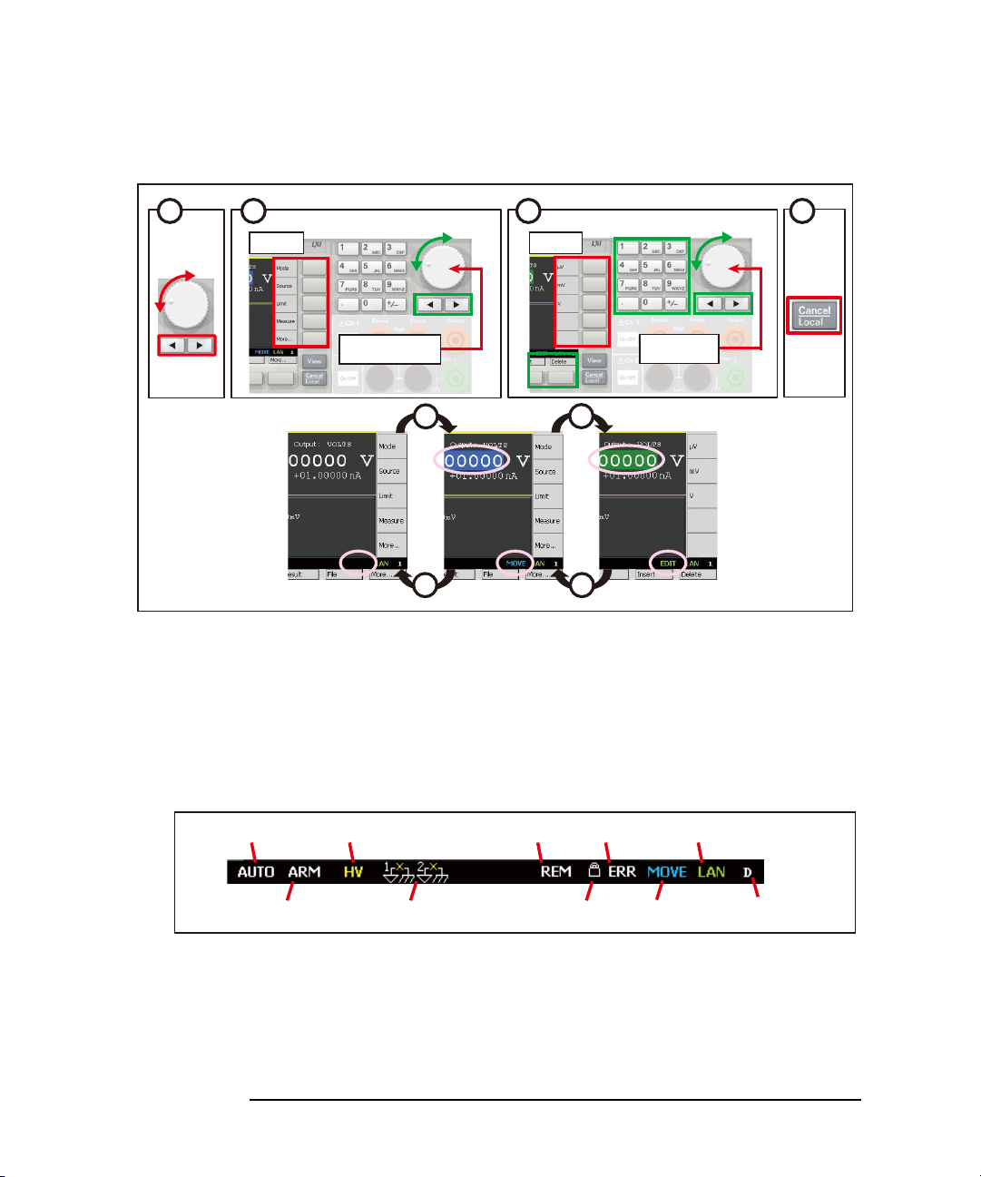
Getting Started
1
2
34
MOVE status EDIT status
1
Press to select
MOVE status
2
EDIT status
3 4
Select
Press to fix
Fix
Trigger auto
Trigger active
High voltage
Floating
Remote
Local lockout
Error
MOVE/EDIT
LXI LAN status indicator
View mode
Operation Tips
Figure 1-2 Editing the Setup
For more information about the fro nt panel k eys, see “Hard Keys and Rotary Knob”
on page 4-3.
If the field pointer is in th e E DIT (green ) status on the Source or Limit field, turning
the knob changes the setting value of the source channel in real time.
Figure 1-3 Status Information
For details about the status information, see “Status Information” on page 4-25.
1-10 Keysight B2961A/B2962A User’s Guide, Edition 3
Page 35

Getting Started
Operation Summary
Operation Summary
This section summarizes front panel operations on B2961A/B2962A.
• “Basic Operations”
• “Channel Setup”
• “Source Setup”
• “Measurement Setup”
• “Display Setup”
• “File Operations”
• “Miscellaneous Functi ons”
• “Interface Setup”
• “System Setup and Operations”
For details about front panel operations, see Chapter 4, “Front Panel Re ference.”
Keysight B2961A/B2962A User’s Guide, Edition 3 1- 11
Page 36

Getting Started
Operation Summary
Table 1-1 Basic Operations
Task Relevant front panel key
To turn the B2961A/B2962A on/off Standby switch
To change the display mode
To enable/disable the specified channel Ch 1
To cancel the previous setup operation
To return to the upper menu of a function key or softkey
To return to the local status from the remote status
To start a single (one shot) output/measurement
To start a repeat (continuous) measurement
View
key
On/Off
Cancel/Local
Cancel/Local
Cancel/Local
Trigger
key
Auto
key
switch or Ch 2
key
key
key
On/Off
switch
To move the field pointer Rotary knob or arrow keys
To move the digit pointer Rotary knob or arrow keys
To switch the EDIT/MOVE status Rotary knob on a setup field
To select the setup value Assist keys, rotary knob, or arrow keys
T o save/recal l all s etup in formatio n of the B2961A /B296 2A Config > Save or Recall function keys
Table 1-2 Channel Setup
Task Relevant front panel key
To enable/disable the specified channel Ch 1
On/Off
switch or Ch 2
On/Off
switch
To select the sensing type; 2-wire or 4-wire Config > Source > Connection function keys
T o select the l ow termi nal s tatu s; gr oun ded or fl oating Config > Source > Connection function keys
To enable/disable high capacitance mode Config > Source > Connection function ke ys
To enable/disable over voltage/current protection Config > Source > Connection function keys
To enable/disable resistance compensation Config > Measure > R Compen function keys
To enable/disable 2-channel synchronous operation Config > Common > Group function keys
1-12 Keysight B2961A/B2962A User’s Guide, Edition 3
Page 37

Table 1-3 Source Setup
Task Relevant front panel key
Getting Started
Operation Summary
To enable/disable source output Ch 1
On/Off
switch or Ch 2
On/Off
switch
To select source output mode Mode, Ch1 Mode, or Ch2 Mode assist key
To set source output value Source, Ch1 Source, or Ch2 Source assist key
To set limit value Limit, Ch1 Limit, or Ch2 Limit assist key
To set function OFF, sweep output
Hide Options/Pulse/Trigger assist key on Si ngle view
(linear single, linear double, log single,
log double, or list), or arbitrary
waveform output (exponent, ramp,
square, sinusoid, trapezoid, triangle, or
user defined)
To set constant source ranging mode Show Options assist key on Single view
To set programmable output resistance Show Options assist key on Single view
To set list sweep source Edit assist key in the EDIT status for the LIST sweep
Start/Stop/Points field
To set sweep source ranging mode Config > Source > Sweep function keys
To set sweep direction Config > Source > Sweep function keys
To set source output value after sweep Config > Source > Sweep function keys
To set pulse source Show Pulse assist key on Single view
To set source wait time Config > Common > Wait function keys
To set output filter Config > Source > Filter function keys
To use external low noise filter Config > Source > Ext. Filter function keys
To set programmable output resistance
Config > Source > Output R function keys
using emulation table
To select output-off status Config > Sour ce > Connection function keys
To enable/disable automatic output ON Config > Source > Connection function keys
To enable/disable automatic output OFF Config > Source > Connection function keys
Keysight B2961A/B2962A User’s Guide, Edition 3 1- 13
Page 38

Getting Started
Operation Summary
Table 1-4 Measurement Setup
Task Relevant front panel key
To enable/disable the specified channel Ch 1
On/Off
switch or Ch 2
On/Off
switch
To select measurement mode Measure, Ch1 Measure, or Ch2 Measure assist key
To set measurement speed Show Options assist key on Single view
To set measurement wait time Config > Common > Wait function keys
Table 1-5 Display Setup
Task Relevant front panel key
To change the display mode
View
key
To change the color set Display > Color function keys
To enable zoom-in Display > Zoom > ON function keys
To disable zoom-in Zoom Out assist key for the zoom-in display status
T o enable/disable the front panel display
Display > Remote function keys
in the remote condition
Table 1-6 File Operations
Task Relevant front panel key
To save a measurement result data to USB memory File > Save > Measure function keys
To save a math result data to USB memory File > Save > Math function keys
To save a trace buffer data to USB memory File > Save > Trace function keys
To save a system setting data to USB memory File > Save > Config function keys
To save a graph screen damp to USB memory Dump Screen assist key on Graph view
To load a system setting data from USB memory File > Load > Config function keys
To load a list sweep data from USB memory Load assist key in the EDIT status for the LIST
sweep Start/Stop/Points field
To load a user defined waveform data from USB
memory
Load assist key in the EDIT status for the ARB
USER Start/Stop/Points fie ld
1-14 Keysight B2961A/B2962A User’s Guide, Edition 3
Page 39

Table 1-7 Miscellaneous Functions
Task Relevant front panel key
To enable/disable Limit for each polarity Display > Pref. function keys
Getting Started
Operation Summary
To enable/disable output/limit real time
update by using digit pointer and knob
To see measurement result Result > Measure function keys
To use math expression Function > Math function keys
To see math result Result > Measure function keys
To set trace buffer Function > Trace function keys
To see trace statistical result Result > Trace function keys
To select program memory Program > Catalog function keys
To control program memory Program > Control function keys
To set trigger parameters easily Show Trigger assist key on Single view
To set trigger parameters in detail Function > Trigger > Config function keys
To control trigger system Function > Trigger > Initiate/Abort/Immediate function keys
Table 1-8 Interface Setup
Task Relevant front panel key
To specify measurement data elements I/O > Format > Measure function keys
Display > Pref. function keys
To specify math data elements I/O > Format > Math function keys
To specify trace statistical data elements I/O > Format > Trace function keys
To select data output format I/O > Format > Data Type function keys
To enable/disable byte swap of binary data I/O > Format > Data Swap function keys
To set LAN configuration I/O > LAN > Config function keys
To see status of LAN interface I/O > LAN > Status function keys
To reset all of LAN connections I/O > LAN > Reset function keys
To sets LAN settings to the default settings I/O > LAN > Default function keys
Keysight B2961A/B2962A User’s Guide, Edition 3 1- 15
Page 40

Getting Started
Operation Summary
Task Relevant front panel key
To enable/disable Media Transfer Protocol
for easy file access
To see status of USB interface I/O > USB function keys
To set GPIB address I/O > GPIB function keys
To see status of GPIB interface I/O > GPIB function keys
To set configuration of Digital I/O I/O > DIO > Config function keys
To read/write a value set to Digital I/O I /O > DIO > R/W function keys
Table 1-9 System Setup and Operations
Task Relevant front panel key
To set power line frequency System > PLC function keys
To return to the factory shipment
condition
To apply initial settings System > Reset function keys
To perform self-calibration System > Cal/Tes t > Self-Cal function keys
To perform self-test System > Cal/Test > Self-Test function keys
To check errors System > Error > Log function keys
I/O > USB function keys
System > More > Factory function keys
To clear error log System > Error > Clear function keys
To clear time stamp System > Timestamp > Clear function keys
To set automatic clear of time stamp System > Timestamp > Auto CLR function keys
To set start-up operation System > More > Start-up function keys
To enable/disable beep and sound System > More > Sound functi on keys
To enable/disable the function to restore
the trigger mode settings on the local state
To set date and time System > More > Info. > Date/Time function keys
To perform firmware update System > More > Info. > Update > Firmware function keys
To perform demonstration System > More > Info. > Demo. function keys
1-16 Keysight B2961A/B2962A User’s Guide, Edition 3
Display > Pref. function keys
Page 41

2Introduction
Page 42

Introduction
This chapter describes the basic functions and features of the Keysight B2961A/
B2962A, and consists of the following sections.
• “Keysight B2961A/B2962A”
• “Front View”
• “Rear View”
• “Power Source”
• “Operation and Functi ons”
• “Software and Drivers”
• “Accessories”
• “Options”
2-2 Keysight B2961A/B2962A User’s Guide, Edition 3
Page 43

Keysight B2961A/B2962A
Keysight B2961A/B2962A
Keysight B2961A/B2962A is 6½ digit low noise power source. B2961A/B2962A
provides the LCD, front pa nel keys , an d ro tar y kn ob f or ap pl ying voltage/current or
measuring voltage/current/resistance. B2961A/B2962A also supports several
functions, such as arbitrary waveform generation, pulse output, sweep output, trace
buffer, math expressions, and graph plot. Hence, B2961A/B2962A can be used as a
DC (constant) voltage/current source, sw eep voltage/current source, pulse gen erator ,
arbitrary waveform generator, and multimeter.
Table 2-1 Keysight B2961A/B2962A 6½ Digit Low Noise Power Source
Effective set and measure value
Introduction
Model
No.
B2961A 1 0.01 pA,
B2962A 2
B2961A/B2962A is a LAN eXtended Interface Core compliant instrument.
Number
of
channels
Minimum
resolution Maximum
Set Measure
0.1 V
1 pA,
10 V
DC: ± 3.03 A
Pulse: ± 10.5 A
current
Maximum
voltage
± 210 V
Keysight B2961A/B2962A User’s Guide, Edition 3 2- 3
Page 44

Introduction
Front View
Front View
This section describes the front view of the Keysight B2961A/B2962A.
• Standby switch
Turns the instrument on or off. When the power is on, the LED below the switch
is turned green.
•Display
Displays the source setup, measurement result, status information, etc. For
details, see Chapter 4, “Front Panel Reference.”
•Trigger key
Starts a single (one shot) output/measurement or initiates trigger system. If a
repeat measurement is in progress, stops it.
The single measurement is performed with the DC bias output, pulsed bias
output, arbitrary waveform output, staircase sweep output, or pulsed sweep
output set to the channel. One single measurement can contain the maximum of
100000 measurement points.
Once a single measurement starts, the data buffer (maximum 100000 data) is
cleared, and the last single measurement result is stored in the buffer. The
measurement result is displayed on the Single view, Dual view, or Graph view.
NOTE If measurement is not performed properly , check the trigger setting. The trigger type
must be set to AUTO, or the trigger count (Count) must be set properly. See
“Trigger Paramet ers” on page 4-20 .
2-4 Keysight B2961A/B2962A User’s Guide, Edition 3
Page 45

Introduction
Front View
• Auto key
Starts a repeat (continuous) measurement. If a repeat measurement is in
progress, stops it.
The repeat measurement is performed with the DC bias output of the Source
value. And the measurement result is displayed on the Single view or Dual view.
The repeat measurement result is not stored in the buffer.
• USB-A connector
Used to connect a USB memory. After discon necting the USB memory, wait 10
seconds before connecting it again or new one.
CAUTION Turning the instrument off while the USB memory is being accessed may damage
the device.
• Function keys
Six function keys are available below the display. They are assigned to the
softkeys, Config, Function, Trigger, Result, File, Program, I/O, Display , System,
and More. For details, see Chapter 4, “Front Panel Reference.”
• Assist keys
Five assist keys are available to the right of the display. They are assigned to
several softkeys, such as Mode, Source, Limit, Measure, and More. The softkey
assignment depends on the display mode (Single, Graph, or Dual). For details,
see Chapter 4, “Front Panel Reference.”
•View key
Changes the display mode. Pressing the key changes the mode as shown below.
On B2961A Single Graph (return to Single)
On B2962A Dual Single for channel 1 Single for channel 2
Graph (return to Dual)
• Cancel / Local key
Cancels the setup operation if the instrument is in the local status. Returns the
instrument to the local status if it is in the remote status.
Keysight B2961A/B2962A User’s Guide, Edition 3 2- 5
Page 46

Introduction
Front View
• Numeric/alpha keys
Used to enter the value of setup parameters such as the source output value, limit
value, and message, specified by the field pointer.
• Rotary knob
If the field pointer is in the MOVE (blue) status, turning the knob moves the
pointer. Pressing the knob fixes the pointer position and changes the pointer
status to EDIT (green).
If the field pointer is in the EDIT (green) status, turning the knob changes the
value of the setup parameter specified by the pointer. Pressing the knob fixes the
value and changes the pointer status to MOVE (blue).
• Left and right keys
If the field pointer is in the MOVE (blue) status, pressing the key moves the
pointer.
If the field pointer is in the EDIT (green) status, pressing the key changes the
value of the setup parameter specified by the pointer.
If the field pointer is in the EDIT (green) status on a numeric value entry field,
pressing the key changes the pointer to a digit pointer.
• On/Off switch(es)
Used to enable or disable the channel. Turns the channel off if it is in the output
status even if it is in the remote status. One switch on 1-channel models, and two
switches on 2-channel models.
The switch turns green if the channel is enabled.
The switch turns red if the channel is in the high voltage state.
• Channel 1 source/measure terminals
Terminals for channel 1. High Force, Low Force, High Sense, Low Sense,
Guard, and chassis ground. For details, see “Connecting a DUT” on page 3-14
CAUTION Never connect the Guard terminal to any output, including circuit common, chassis
ground, or any other guard terminal. Doing so will damage the B2961A/B2962A.
CAUTION Do not apply current to the chassis ground terminal. Doing so will damage the
B2961A/B2962A.
2-6 Keysight B2961A/B2962A User’s Guide, Edition 3
Page 47

Rear View
This section describes the rear view of the Keysight B2961A/B2962A.
• Channel 2 source/measure terminals
Only on 2-channel models. Terminals for channel 2. High Force, Low Force,
High Sense, Low Sense, Guard, and chassis ground. For details, see
“Connecting a DUT” on page 3-14
Introduction
Rear View
CAUTION Never connect the Guard terminal to any output, including circuit common, chassis
ground, or any other guard terminal. Doing so will damage the B2961A/B2962A.
CAUTION Do not apply current to the chassis ground terminal. Doing so will damage the
B2961A/B2962A.
• GPIB interface connector
Use a Keysight 82357A/B USB/GPIB interface or Keysight 10833A/B/C/D
GPIB cable to connect to an external computer or equipment.
• Cooling fan
• AC input connector
AC power cord is connected to this receptacle.
• LAN interface connector
Connects to 10/100 Base-T interface. Left LED indicates activity. Right LED
indicates link integrity.
Keysight B2961A/B2962A User’s Guide, Edition 3 2- 7
Page 48

Introduction
Rear View
• USB-B connector
Connects to USB interface.
• Digital I/O connector
D-sub 25 pin female connector for general purpose I/O (GPIO). Can be used as
trigger input/output terminals or as an interface to a handler or the likes. For
details, see “Using Digital I/O” on page 3-37
Pins 16 and 24 and pins 17 and 25 are reserved for the interlock function. If the
terminals are open, the instrument output is limited to ±42 V. Be sure to connect
the terminals to the Keysight 16442B test fixture or another DUT interface
before performing measurements. If you do not use 16442B, you need to install
an interlock circuit. For details on how to install the interlock circuit, see
“Installing the Interlock Circuit” on page 3-27.
WARNING Dangerous voltage, instrument maximum output voltage may appear at the
High Force, High Sense, and Guard terminals if the Interlock terminal is
closed.
Une tension dangereuse, une tension de sortie maximale de l'appareil peut
apparaître aux bornes High Force, High Sense et Guard si la borne Interlock
est fermée.
NOTE Serial Number
Y o u will need the instrument’ s serial number when using the Keysight T echn ologies
telephone assistance program. The serial number label is attached to the bottom of
the instrument.
2-8 Keysight B2961A/B2962A User’s Guide, Edition 3
Page 49

Power Source
High Force
Chassis ground
High Sense
4-wire connections
Low Sense
Low Force
High Force
Chassis ground
Low Force
2-wire connections
DC
Current
and
Voltage
Monitor
(4½ digit)
DC
Current
and
Voltage
Monitor
(4½ digit)
The power source can apply voltage or current, and can measure current or voltage.
Figure 2-1 shows a simplified power source circuit diagrams. The power source can
perform the following operations.
• Applies voltage and measures current
• Applies current and measures voltage
• Applies voltage and measures voltage
• Applies current and measures current
Figure 2-1 Simplified Power Source Circuit Diagram
Introduction
Power Source
Keysight B2961A/B2962A User’s Guide, Edition 3 2- 9
Page 50

Introduction
Power Source
Measurement Parameters
B2961A/B2962A supports the following measurement parameters.
• Current
• Voltage
• Resistance
•Power
• Percent-to-Limit (= measured value / Limit value 100 %)
Resistance data is given by Resistance = Vmeas / Imeas.
Power data is given by Power = Vmeas Imeas.
In the above formula, Vmeas is the voltage measurement data, and Imeas is the
current measurement data.
For using the resistance compensation, see “Resistance Compensation” on page
6-18.
NOTE Measurement Range
Voltage source uses the present output range to measure voltage and/or the
minimum range which covers the Limit value to measure current.
Current source uses the present output range to measure current and/or the minimum
range which covers the Limit value to measure voltage.
Limit
B2961A/B2962A has a compliance feature that limits the output voltage or current
to prevent damage to the device under test. When the channel applies voltage, you
can specify the current limit. When the channel applies current, you can specify the
voltage limit. For details, see “Limit/Compliance” on page 6-3.
2-10 Keysight B2961A/B2962A User’s Guide, Edition 3
Page 51
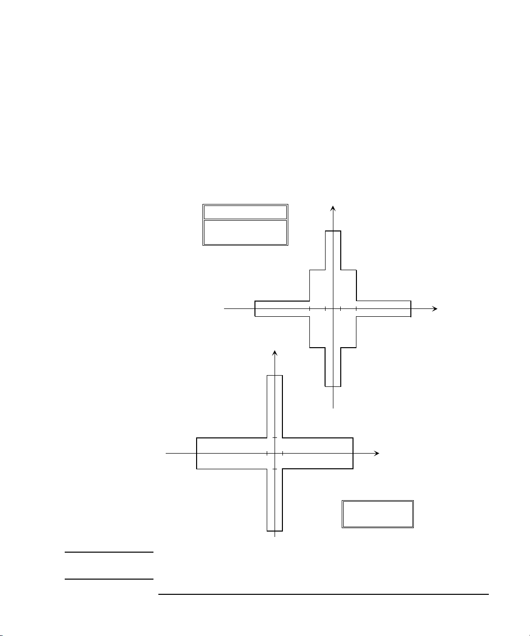
Output and Measurement Ranges
6
10.5
10.5
Voltage (V)
Current (A)
6
1.515
-
-
-
1.515
Pulsed output
200
200
-
-
210
210
6
3.03
3.03
Voltage (V)
Current (A)
6
0.105
-
-
-
0.105
DC output
1.515
1.515
-
-
21
21
Duty cycle ~ 2.5 %
Duty cycle ~ 99.9999 %
Pulsed output
This section describes typical specifications of the Keysight B2961A/B2962A.
• Maximum voltage and current: see Figure 2-2.
• Maximum power: 31. 8 W
• Output/measurement value and resolution: see Table 2-2 to Table 2-6.
Figure 2-2 Maximum Voltage and Current
Introduction
Power Source
NOTE For using the arbitrary waveform output function or an external filter (N1294A-020/
021/022 low noise filter), the range of DC output is applied.
Keysight B2961A/B2962A User’s Guide, Edition 3 2- 11
Page 52

Introduction
Power Source
Table 2-2 Current Output Range
Maximum voltage
DC
output
Pulsed
output
Pulse width t
Range
value
Setting
resolution
DC output current or
pulse peak/base
current
a b
10 nA 10 fA 0 |I| 10.5 nA 210 V 210 V 50 s t t
100 nA 100 fA 0 |I| 105 nA
1 A 1 pA 0 |I| 1.05 A
10 A 10 pA 0 |I| 10.5 A
100 A 100 pA 0 |I| 105 A
1 mA 1 nA 0 |I| 1.05 mA
10 mA 10 nA 0 |I| 10.5 mA
100 mA 100 nA 0 |I| 105 mA
1 A 1 A0 |I| 105 mA
105 mA < |I| 1.05 A 21 V 21 V
0 |I| 1.05 A 200 V 50 s t 2.5 ms
180 V 50 s t 10 ms
1.5 A 0 |I| 105 mA 210 V 210 V 50 s t t
105 mA < |I| 1.515 A 21 V 21 V
c
max
max
0 |I| 1.515 A 200 V 50 s t 2.5 ms
0 |I| 1.05 A 180 V 50 s t 10 ms
3 A 10 A0 |I| 105 mA 210 V 210 V 50 s t t
max
105 mA < |I| 1.515 A 21 V 21 V
1.515 A < |I| 3.03 A 6 V 6 V
10 A 0 |I| 10.5 A 6 V 50 s t 1 ms
0 |I| 1.515 A 200 V 50 s t 2.5 ms
0 |I| 1.05 A 180 V 50 s t 10 ms
2-12 Keysight B2961A/B2962A User’s Guide, Edition 3
Page 53

a. Table 2-4 shows the limitations when using Channels 1 and 2 for DC output or
Pulsed output with 50 s t t
b. Maxi mum base curr ent is 500 mA for the pulse with 50 s t 1 ms, and 50 mA for
the pulse with 50 s t 2.5 ms or 50 s t 10 ms.
c. Maximum duty cycle is 99.9999 % for the pulse with 50 s t t
the pulse with 50 s t 1 ms, 50 s t 2.5 ms, or 50 s t 10 ms.
Table 2-3 Voltage Output Range
(=99.9999 ks).
max
, and 2.5 % for
max
Introduction
Power Source
Pulsed
output
a
Pulse width t
Range
value
Setting
resolution
DC output voltage
or pulse peak/base
voltage
Maximum current
DC
output
0.2 V 0.1 V0 |V| 0.21 V 3.03 A 3.03 A with 50 s t t
2 V 1 V0 |V| 2.1 V
10.5 A with 50 s t 1 ms
20 V 10 V0 |V| 6 V
6 V < |V| 21 V 1.515 A 1.515 A with 50 s t t
200 V 100 V0 |V| 6 V 3.03 A 3.03 A with 50 s t t
10.5 A with 50 s t 1 ms
6 V < |V| 21 V 1.515 A 1.515 A 50 s t t
21 V < |V| 210 V 105 mA 105 mA
0 |V| 180 V 1.05 A 50 s t 10 ms
0 |V| 200 V 1.515 A 50 s t 2.5 ms
a. T able 2-4 shows the limitations when using Channels 1 and 2 for DC output or Pulsed
output with 50 s t t
b. Maximum duty cycle is 99.9999 % for the pulse with 50 s t t
(=99.9999 ks).
max
, and 2.5 % for
max
the pulse with 50 s t 1 ms, 50 s t 2.5 ms, or 50 s t 10 ms.
b
max
max
max
max
Keysight B2961A/B2962A User’s Guide, Edition 3 2- 13
Page 54

Introduction
Power Source
Table 2-4 Limitations for using Channels 1 a nd 2
Channel 1 voltage V1 Channel 2 voltage V2
0 < |V1| 6 V 0 < |V2| 6 V I1 + I2 4 A
6 V < |V1| 21 V 0 < |V2| 6 V I1 + I2 0.625 2.5 A
a. I1: Channel 1 current, I2: Channel 2 current
Table 2-5 Current Measurement Range
Range value Current measurement value Resolution
10 nA 0 |I| 10.6 nA 1 pA
100 nA 0 |I| 106 nA 10 pA
1 A0 |I| 1.06 A 100 pA
10 A0 |I| 10.6 A1 nA
100 A0 |I| 106 A 10 nA
1 mA 0 |I| 1.06 mA 100 nA
Current limit
a
6 V < |V2| 21 V I1 + I 2 1.6 4 A
6 V < |V2| 21 V I1 + I2 2.5 A
10 mA 0 |I| 10.6 mA 1 A
100 mA 0 |I| 106 mA 10 A
1 A 0 |I| 1.06 A 100 A
1.5 A 0 |I| 1.53 A
3 A 0 |I|
a
10 A
3.06 A 1 mA
0 |I| 10.6 A
a. Available for pulse mode. Not available for DC mode.
2-14 Keysight B2961A/B2962A User’s Guide, Edition 3
Page 55

Table 2-6 Voltage Measurement Range
Range value Voltage measurement value Resolution
0.2 V 0 |V| 0.212 V 10 V
2 V 0 |V| 2.12 V 100 V
20 V 0 |V| 21.2 V 1 mV
200 V 0 |V| 212 V 10 mV
Introduction
Power Source
Keysight B2961A/B2962A User’s Guide, Edition 3 2- 15
Page 56

Introduction
Operation and Functions
Operation and Functions
Front Panel Interface
4.3” color TFT WQVGA (480272, with LED backlight) provides a graphical user
interface (GUI) with the following features.
• Single, Dual view, and time domain view (voltage vs time or current vs time) on
Graph view
• Preview of output w aveform
• Easy-to-use key operations
• Easy access to basic and advanced source/measurement capabilities
Single view
Single view provides basic and advanced settings and display capabilities for a
selected channel from the front panel of the instrument. The DC, pulse and
integrated arbitrary waveform generation capabilities do not require any additional
controller or software. The GUI has a feature that allows you to preview an ar bitrary
waveform before application. It also displays the measured voltage and current for
the selected channel with 4.5 digits of resolution.
Dual view
Dual view allows you to view both channels simultaneously and provides basic
setting and display capabilities. It also displays the measured voltage and current for
both channels 1 and 2 with 4.5 digits of resolution. This mode is available only for
the B2962A.
Graph view
Graph view displays measurement results in the time-domain (V-t or I-t curves) for
up to 2 channels. This is useful for quick checking and debug of the output
waveform(s).
Easy-to-Use Key Operations
• Numeric/alpha keys, assist keys, and rotary knob for easy operation
• Numeric/alpha keys enable direct input of alphanumeric values.
• Assist key guides operation on the front panel.
2-16 Keysight B2961A/B2962A User’s Guide, Edition 3
Page 57

Easy Access to Source/Measurement Capabilities
• Settings:
• V/I source mode
• Source value
• Limit value
• Sweep parameters
• Pulse parameters
• Parameters for built-in waveform
• Measure speed
• Range setting
• Trigger setting
•Displays:
• Numeric display in 6 1/2 digits for sourcing
• Numeric display in 4 1/2 digits for monitoring
Introduction
Operation and Functions
• V-t / I-t curve in Graph view
• Advanced Capabilities:
• Trace memory for accumulating measurement (or math) result and collecting
their statistics
• File Operations (USB memory):
Save:
• System configuration
• Measurement/math result
•Trace data
• Graph screen dump
Load:
• System configuration
• List sweep data
• User-defined arbitrary waveform data
Keysight B2961A/B2962A User’s Guide, Edition 3 2- 17
Page 58

Introduction
Operation and Functions
Program and Interface Capabilities
Programming Language
The B2961A/B2962A supports SCPI (Standard Commands for Programmable
Instruments).
Program Memory
Program memory allows you to s t ore lo ng s t ring s o f S CPI co mmand l ines once in to
the B2961A/B2962A's volatile memory and then recall those strings multiple times
while the program is executing using a single SCPI command. By storing the
command strings in memory, the time that would have been spent sending those
same commands over a communication bus is eliminated. For tests that utilize lots
of repeated code (such as subroutines), program memory can dramatically reduce
test times.
• Maximum number of characters of program name: 32 with alphabets, numbers,
hyphens, and underscores
• Maximum memory size: 100 KB (2500 lines typical)
LXI
LXI core conformant. The B2961A/B2962A follows specified LAN protocols and
adhere to LXI requirements such as a built-in Web control server and IVI-COM
driver.
• Ethernet: 10/100Base-T
• USB2.0: USB-TMC488 protocol (rear 1)
• GPIB: IEEE-488.2 compliant
USB File System
USB 2.0 high-speed mass storage (MSC) class device (front 1)
2-18 Keysight B2961A/B2962A User’s Guide, Edition 3
Page 59

Operation and Functions
Digital I/O Interface
• Connector: 25-pin female D
• Input/output pins: 14 open drain I/O bits
• Absolute maximum input voltage: 5.25 V
• Absolute minimum input voltage: -0.25 V
• Logic low maximum input voltage: 0.8 V
• Logic high minimum input voltage: 2.0 V
• Maximum source current: 1 mA, Vout = 0 V
• Maximum sink current: 50 mA, Vout = 5 V
• 5 V power supply pin:
Limited to 600 mA, solid state fuse protected
• Safety interlock pin:
One active high pin and one active low pin. Activation of both pin enables
output voltage > 42 V.
Introduction
Keysight B2961A/B2962A User’s Guide, Edition 3 2- 19
Page 60

Introduction
Software and Drivers
Software and Drivers
• Keysight B2900A Quick I/V Measurement Software
The B2961A/B2962A includes PC-based Keysight B2900A Quick I/V
Measurement Software. This powerful software makes it easy to quickly setup
and perform I/V measurements and to display the measurement data in a table or
graph without the need to perform any programming. The software allows you
to control up to four channels over a GPIB or LAN connection, or one B2900
via a USB connection.
System requirements:
• Windows 7 (64 bit/32 bit), XP SP3 (32 bit)
• Microsoft .NET framework 4.0 or later
• Keysight IO Libraries 16.0 or later
• Graphical Web Interface
The Graphical W eb Interface is a web brow ser based instrument control panel. It
enables you to set up and perform a measurement easily and q uickly f rom a web
browser using the built-in web server. This allows you to control one instrument
over a LAN connection.
• IVI-C or IVI-COM dr ivers
Compatible with W in dows 7 (64 bit/32 b it), XP SP 3 (32 bit ) IO Librari es 16.0 o r
later. Supports Keysight VEE, Microsoft Visual Studio (Visual Basic, Visual
C++, Visual C#), National Instruments LabWindows and LabVIEW.
• LabVIEW driver (VI)
National Instruments LabVIEW 7.0 or later. LabView drivers are available at
NI.COM.
NOTE For the latest system requirements, go to www.keysight.com/find/b2960a and get
the information.
2-20 Keysight B2961A/B2962A User’s Guide, Edition 3
Page 61

Introduction
Accessories
Accessories
Furnished Accessories
The Keysight B2961A/B2962A is furnished with the following accessories.
• Quick Reference, 1 ea.
• Product Reference CD-ROM, 1ea.
• Keysight IO Libraries CD-ROM, 1ea.
• Power cord, 1 ea.
• USB cable, 1 ea.
The Product Reference C D-RO M st or es Ke ys ight B 29 00A Quick I/ V Meas uremen t
Software, sample programs, and user manuals.
Available Accessories
For the available accessories for the Keysight B2961A/B2962A, see the catalog
Accessories for the Keysight B2900 Precision Instrument Family.
T o get the latest catalog, go to www.keysight.com/find/b2960a and click “Technical
Support” and “Catalogs”.
Keysight B2961A/B2962A User’s Guide, Edition 3 2- 21
Page 62

Introduction
Options
Options
Table 2-7 lists the options for the Keysight B2961A/B2962A.
Table 2-7 Options
Option Description
External Low Noise Filter
LN0 High Current Ultra low noise filter, 21 V / 500 mA, 10
LN1 Ultra low noise filter, 42 V / 105 mA, 50 (N1294A-021)
LN2 Low noise filter, 210 V / 3 A (N1294A-022)
Calibration
UK6 Commercial calibration certificate with test data
(N1294A-020)
A6J ANSI Z540 compliant calibration
Printed Manual (User’s Guide)
ABA English
ABJ Japanese
Rack Mount Kit
1CM Rack mount kit
2-22 Keysight B2961A/B2962A User’s Guide, Edition 3
Page 63

3 Installation
Page 64

Installation
This chapter describes how to install Keysight B2961A/B2962A and accessories
and consists of the following sections.
• “Inspecting the Shipment”
• “Installing the Keysight B2961A/B2962A”
• “Maintenance”
• “Connecting a DUT”
• “Installing the Interlock Circuit”
• “Connecting to the Interfaces”
• “Communicating Over the LAN”
• “Using Digital I/O”
WARNING To avoid electrical shock and instrument damage, turn the instrument off
before connecting or disconnecting measurement cable.
Mettez la machine hors tension pour fixer le connecteur ou pour retirer le
connecteur de l’unité centrale.
WARNING There are potentially hazardous voltages (210 V) present at the High Force,
High Sense, and Guard termin als of this instrument. To prevent electrical
shock, the following safety precautions must be observed during the use of the
instrument.
• Use a three-conductor AC power cord to connect the cabinet (if used) and
the instrument to an electrical ground (safety ground).
• If an interlock circuit is not installed in your test fixture or connection
interface, you must install and connect the interlock circuit that opens the
interlock terminal when the shielding box access door is opened.
• If you change the connection interface, test fixture, prober, and such,
connect an interlock cable to the one actually used.
• Confirm periodically that the interlock function works normally.
• B efore touching the connections on the High Force, High Sense, a nd Gu ard
terminals, turn the instrument off and discharge any capacitors. If you do
not turn the instrument off, complete all of the following items, regardless
of the instrument settings.
•Press the
3-2 Keysight B2961A/B2962A User’s Guide, Edition 3
On/Off
switch, and confirm that the switch turns off.
Page 65

Installation
• Confirm that the
• Open the fixture cover or the shielding box access door (open interlock).
• Discharge any capacitors connected to a channel.
• Warn persons working around the instrument about dangerous conditions.
WARNING Une tension dangereuse (max. pour; 210 Vdc) émanant du dispositif
l'instrument peut être sortie aux bornes High Force, High Sense et Guard. Les
précautions suivantes doivent être obserées contre commotion électrique
accidentelle.
• Utilisez un cordon d'alimentation CA à trois connecteurs pour connecter la
cabine (si utilisée) et l'instrument à la mise électrique à la terre (sol de
sécurité).
• Si un circuit de sécurité n'est pas instal lé dans votre test d'installation ou
dans votre interface de connexion, vous devez installer et connecter le
circuit de sécurité qui ouvre la borne d'enclenchement lorsque la porte
d'accès à la protection de la boîte est ouverte.
• Si vous changez l'interface de connexion, un test d'installation, la sonde, ou
toute autre élément, connectez un cordon d'enclenchement à celui utilisé
actuellement.
• Vérifiez régulièrement que la fonction de verrouillage fonctionne
normalement.
On/Off
switch does not turn red.
• Avant de toucher les connexions de s bornes High Force, High Sense et
Guard, éteignez l'instrument et déchargez tous les condensateurs. Si vous
n'éteignez pas l'appareil, complétez tous les éléments suivants,
indépendamment des réglages de l'appareil.
• Appuyez sur le bouton On/Off, et confirmez que le signal lumineux est
éteint.
• Vérifiez que le bouton On/Off ne devienne pas rouge.
• Ouvrez le couvercle d'appareil ou la protection du boîtier de la porte
d'accès (verrouillage ouvert).
• Déchargez tous les condensateurs connectés au réseau.
• Informez les personnes se trouvant à proximité de l'appareil à propos des
conditions dangereuses.
Keysight B2961A/B2962A User’s Guide, Edition 3 3- 3
Page 66

Installation
Inspecting the Shipment
Inspecting the Shipment
Perform the following inspections when the Keysight B2961A/B2962A and
accessories arrive at your site.
1. Be fore unpacking any co mponent, inspect all boxes f or any signs of damage that
might have occurred during shipment, such as:
•dents
• scratches
•cuts
• water marks
If you suspect any damage, contact your nearest Keysight Sales and Support
Office.
2. When you open the boxes that contain the B2961A/B2962A and accessories,
check the components against the contents lists attached to the boxes.
If anything is missing, contact your nearest Keysight Sales and Support Office.
3. Verify the operation of B2961A/B2962A as described in “Checking the
Operation of Keysight B2961A/B2962A” on page 3-4.
If any problem occurs, contact your nearest Keysight Sales and Support Office.
Checking the Operation of Keysight B2961A/B2962A
1. Make sure that the standby switch is set to off.
2. Connect the power cord from the B2961A/B2962A’s rear panel AC input
connector (receptacle) to an AC power outlet at your site.
3. Press the standby switch to turn on the instrument.
The initialization screen will appear on the B2961A/B2962A’s front panel
display, and the power-on self-test is automatically executed.
If the B2961A/B2962A is operating normally, the front panel LCD displays as
shown in Figure 3-1 or 3-2.
3-4 Keysight B2961A/B2962A User’s Guide, Edition 3
Page 67

Figure 3-1 Display Example for 1-ch Model
Figure 3-2 Display Example for 2-ch Model
Installation
Inspecting the Shipment
Checking for Errors
Errors can be checked as described below.
1. Press the Mor e > Sys tem > Erro r > Lo g function keys. This opens the E rror Log
dialog box .
2. Check the errors displayed on the dialog box.
If no error is detected, “0, No Error” is displayed.
3. Press the OK softkey to close the dialog box.
Keysight B2961A/B2962A User’s Guide, Edition 3 3- 5
Page 68

Installation
Installing the Keysight B2961A/B2962A
Installing the Keysight B2961A/B2962A
This section describes information you must pay attention to when installing the
Keysight B2961A/B 296 2A.
• “Safety Considerations”
• “Environment”
• “Connecting the Power Cord”
• “Setting the Power Line Frequency”
• “Setting Date and Time”
• “Bench Installation”
• “Rack Installation”
Safety Considerations
Refer to the Safety Summary page at the beginning of this guide for general safety
information. Before installation or operation, check the B2961A/B2962A and
review this guide for safety warnings and instructions. Safety warnings for specific
procedures are located at appropriate places throughout this guide.
Environment
WARNING Do not operate the instrument in dusty environment, or in the presence of
flammable gases, corrosive gases, or fumes.
Ne pas utiliser l’appareil dans un endroit poussiéreux, ou en présence de gaz
inflammables, corrosifs ou de fumée.
Environmental conditions for the B2961A/B2962A are described below. The
B2961A/B2962A is designed for use in indoor facilities.
• T emp e rature rang e
Operating 0 C to +55 C
Storage -30 C to +70 C
• Humidity range
Operating 30 % to 80 % RH, non-condensing
3-6 Keysight B2961A/B2962A User’s Guide, Edition 3
Page 69

Installation
Installing the Keysight B2961A/B2962A
Storage 10 % to 90 % RH, non-condensing
• Altitude
Operating 0 m to 2,000 m (6,561 ft.)
Storage 0 m to 4,600 m (15,092 ft.)
• Power requirement: 100-240 V (±10 %), 50/60 Hz
• Maximum volt-amps (VA): 250 VA
•Dimensions
Without handle and feet: 88 mm (H) 213 mm (W) 450 mm (D)
Bench configuration (with handle and feet): 180 mm (H) 260 mm (W) 480
mm (D)
Fan cools the instrument by drawing air through the sides and exhausting it out the
back. The instrument must be installed in a location that allows sufficient space at
the sides and back of the instrument for adequate air circulation.
Connecting the Power Cord
WARNING FIRE HAZARD: Use only the power cord supplied with your instrument.
Using other types of power cord may cause overheating of the power cord,
resulting in fire.
SHOCK HAZARD: The power cord provides the chassis ground through a
third conductor. Be sure to connect to a three-conductor type power outlet with
the correct pin grounded.
RISQUE D’INCENDIE : utilisez uniquement le câble d'alimentation fourni
avec votre appareil. L’utilisation d’autres types de câble d’aliment ation peut
provoquer une surchauffe du câble d’alimentation et provoquer un incendie.
RISQUE DE CHOC ÉLECTRIQUE: le câble d’alimentation fournit la masse
du châssis par le biais d’un troisième conducteur. Assurez-vous de connecter la
prise d'alimentation de type trois conducteurs av ec la broche correcte mise à la
terre.
NOTE The detachable power cord may be used as an emergency disconnecting device.
Removing the power cord will disconnect AC input power to the instrument.
Keysight B2961A/B2962A User’s Guide, Edition 3 3- 7
Page 70
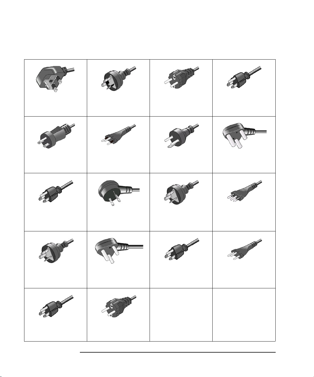
Installation
Installing the Keysight B2961A/B2962A
Option 900
• Plug: BS 1363/A,
250 V, 10 A
• PN: 8120-4420
Option 904
• Plug: NEMA 6-15P,
250 V, 10 A
• PN: 8120-3996
Option 918
• Plug: JIS C 8303,
125 V, 12 A
• PN: 8121-0743
Option 922
Option 901
• Plug: AS/NZS 3112,
250 V, 10 A
• PN: 8120-4419
Option 906
• Plug: SEV 1011,
250 V, 10 A
• PN: 8120-4416
Option 919
• Plug: Israel SI 32,
250 V, 10 A
• PN: 8121-0724
Option 923
Option 902
• Plug: IEC 60277-1,
250 V, 10 A
• PN: 8121-1226
Option 912
• Plug: SB 107-2-D1,
250 V, 10 A
• PN: 8121-1655
Option 920
• Plug: IRAM 2073,
250 V, 10 A
• PN: 8121-0725
Option 927
Option 903
• Plug: NEMA 5-15P,
125 V, 10 A
• PN: 8120-6825
Option 917
• Plug: IS 1293 and
IS 6538, 250 V, 10 A
• PN: 8121-1690
Option 921
• Plug: CEI 23-16,
250 V, 10 A
• PN: 8121-0722
Option 930
• Plug: GB 1002
figure 3, 250 V, 10 A
• PN: 8120-8376
Option 931
• Plug: CNS 10917-2,
125 V, 10 A
• PN: 8121-1635
• Plug: SANS 164-1,
250 V, 10 A
• PN: 8121-0564
Option 932
• Plug: CS 0017,
250 V, 10 A
• PN: 8121-1638
• Plug: NEMA WD-6,
250 V, 10 A
• PN: 8120-0674
• Plug : NBR 14136,
250 V, 10 A
• PN: 8121-1809
3-8 Keysight B2961A/B2962A User’s Guide, Edition 3
Page 71

Installation
Installing the Keysight B2961A/B2962A
Connect the power cord to the IEC 60320 connector on the rear of the instrument. If
the wrong power cord was shipped with your instrument, contact your nearest
Keysight Sales and Support Office.
The AC input on the back of your instrument is a universal AC input. It accepts
nominal line voltages in the range of 100 to 240 VAC.
Setting the Power Line Frequency
The power line frequency must be set properly for the AC power at your site. Press
the following function keys to set the frequency to 50 Hz or 60 Hz.
• For setting to 50 Hz: More > System > PLC > 50 Hz
• For setting to 60 Hz: More > System > PLC > 60 Hz
Setting Date and Time
You can set the date and time on the Date and Time dialog box opened by pressing
System > Info. > Date/Time function keys.
Bench Installation
Do not block the air intake at the sides and the exhaust at the rear of the B2961A/
B2962A. Minimum clearances for bench operation are 5 mm along the sides and
100 mm along the back.
For easier display viewing and measurement terminal access, you can tilt up the
front of the instrument by turning the handle. To adjust the handle, grab the handle
by the sides and pull outward. Then, rotate the handle to the desired position.
Keysight B2961A/B2962A User’s Guide, Edition 3 3- 9
Page 72

Installation
1
1
2
3
Installing the Keysight B2961A/B2962A
Rack Installation
NOTE Use the Rack Mount kit (Option 1CM) to rack mount the Keysight
B2961A/B2962A.
Keysight B2961A/B2962A can be mounted in a 19-inch EIA rack cabinet. It is
designed to fit in two rack-units (2U) of space.
Remove the front and rear rubber bumpers and the hand le befor e rack mou nting the
B2961A/B2962A.
Do not block the air intake at the sides and the exhaust at the rear of the B2961A/
B2962A.
Removing the Bumper
Stretch a corner of the rubber bumper and slide it off.
Removing the Handle
1. Grab the handle by the sides and pull outward. This will allow you to rotate the
handle.
2. Rotate the handle to a vertical position. Then, position the instrument
horizontally.
3. Pull outward and then lift the handle upward.
CAUTION When reattaching the handle, pay attention to its direction. Incorrect attachment
may damage the hardware.
3-10 Keysight B2961A/B2962A User’s Guide, Edition 3
Page 73

Installation
Maintenance
Maintenance
Maintenance should be performed periodically to keep the Keysight B2961A/
B2962A in good condition. If problems arise, contact your nearest Keysight Sales
and Support Office.
• “Cleaning”
• “Self-test”
• “Self-calibration”
• “Calibration”
Cleaning
WARNING SHOCK HAZARD: To prevent electric shock, unplug the B2961A/B2962A
before cleaning.
Risques de choc électrique : afin d’éviter tout choc électrique, débranchez le
B2961A/B2962A avant d’effect uer le net toy age.
Use a dry cloth or a cloth slightly dampened with water to clean the external case
parts. Do not use detergents or chemical solvents. Do not attempt to clean internally.
Self-test
Keysight B2961A/B2962A provides the self-test function to check the operation.
The self-test is automatically performed when the instrument is turned on. It is
recommended to perform the self-test for the following condition or purpose. Before
performing the self-test, turn the channel output off and disconnect test leads and
cables from the terminals.
• If a channel is in the lock condition due to over temperature
In this condition, the Emer gency dial og box is disp layed on the gray background
screen, however this is not shown in the remote status if the remote display is set
to OFF. And the ERR indicator turns on and the On/Off switch is not effective.
Perform the self-test to unlock the channel. The channel can be used soon if the
self-test does not report any problem.
• If you feel that the instrument may be defective
Keysight B2961A/B2962A User’s Guide, Edition 3 3- 11
Page 74

Installation
Maintenance
• For preventive maintenance
To perform
self-test
To perform
self-calibration
The following procedure shows how to perform the self-test.
1. If it is in the remote state, press the Cancel / Local key.
2. Press the On/Off switch and confirm that the switch turns off.
3. Disconnect test leads and cables from the channel terminals.
4. Press the following function keys.
More > System > Cal/Test > Self-Test
Confirmation dialog box is opened.
5. Press the OK key. This starts the self-test.
Self-calibration
Keysight B2961A/B2962A provides the self-calibration function to maintain the
measurement performance. If the environmental temperature changes 3 C or
more, perform the self-calibration. This is effective for the accurate measurements
by minimizing the effect of thermal drift. The self-calibration must be performed
after warming-up of 60 minutes. Before performing the self-calibration, turn the
channel output off and disconnect test leads and cables from the terminals.
The following procedure shows how to perform the self-calibration.
1. If it is in the remote state, press the Cancel / Local key.
2. Press the On/Off switch and confirm that the switch turns off.
3. Disconnect test leads and cables from the channel terminals.
4. Press the following function keys.
More > System > Cal/Test > Self-Cal
Confirmation dialog box is opened.
5. Press the OK key. This starts the self-calibration.
3-12 Keysight B2961A/B2962A User’s Guide, Edition 3
Page 75

Installation
Maintenance
Calibration
Calibration and adjustments must be performed periodically so that the instruments
satisfy the specifications, and keep a good condition. It is recommended to perform
the calibration once a year at least. For the calibration and adjustments , contact your
nearest Keysight Sales and Support Office. Trained service personnel will perform
the calibration and adjustments.
Keysight B2961A/B2962A User’s Guide, Edition 3 3- 13
Page 76

Installation
Connecting a DUT
Connecting a DUT
This section describes how to connect a device under test (DUT) to the Keysight
B2961A/B2962A source/measure terminals.
NOTE Set the channel output off when changing the connections. If not, the DUT may be
damaged.
To set the channel output off, press the
LED turns off.
This section includes the following descriptions.
• “2-Wire Connections or 4-Wire Connections”
• “Floating”
• “Using Test Leads”
• “Using the Low Noise Filter”
• “Using the N1295A Test Fixture”
• “Using the 16442B Test Fixture”
• “Guarding”
NOTE Connecting the interlock circuit
B2961A/B2962A provides an interlock function to prevent the user from receiving
an electrical shock from high voltages over 42 V. If the Digital I/O interlock
terminal is open, B2961A/B2962A cannot apply a high voltage.
For high voltage measurement, connect the interlock terminal to the interlock circuit
as described in “Installing the Interlock Circuit” on page 3-27.
WARNING To avoid touching the end of the extension cable or the terminal area with the
DUT, cover over the conductors with insulator. Also it is important to protect
the terminal area by using the grounded shield cover and such.
On/Off
switch and confirm that the switch
To prevent electrical shock and DUT damage, do not connect or disconnect the
DUT while the instrument is applying voltage or current.
When you touch the DUT after measurement, devise a countermeasure of
residual charge and heat to prevent electrical shock and burn. Use glove and
any tool. Al so have enough time for discha rge and radiation.
3-14 Keysight B2961A/B2962A User’s Guide, Edition 3
Page 77

Installation
Connecting a DUT
Afin d'éviter de toucher l'extrémité du câble d'allongement ou l'aire de la
borne avec l'appareil mis sous tension (AST), couvrez les conducteurs avec
l'isolant. En outre, il est important de protéger la zone de la borne en utilisant
le couvercle d'écran à la mise à terre, ou tout autre élément.
Afin d’éviter toute décharge électrique et dommage MST, ne branch ez ou
déconnectez pas la sortie MST alors que la source de sortie est appliquée.
Lorsque vous touchez le MST après la mesure, élaborez une contre-mesure de
la charge résiduelle et du chauffage afin d'éviter tout choc électrique et toute
brûlure. Utilisez des gants et des outils. Prévoyez également du temps pour la
décharge et la radiation.
2-Wire Connections or 4-Wire Connections
When connecting a DUT, you can choose the connection type either 2-wire
connections or 4-wire connections.
If you want to simplify the connections, use 2-wire connections by connecting the
Force terminals only and opening the Sense terminals. The Force terminals can be
used to apply and measure voltage or current.
T o apply vo ltag e accur ately, use 4-wire connections, remote sensing, well known as
Kelvin connections. Connecting the Force and Sense lines together at the device end
eliminates the voltage drop caused by the residual resistance of the test leads or
cables.
To specify the connection type (Sensing Type), perform the following procedure.
1. Press the Config > Source > Connection function keys. This opens the Output
Connection dialog box.
2. Set the Sensing Type on this dialog box. Choose 2-WIRE for 2-wire
connections, or 4-WIRE for 4-wire connections.
3. Press the OK softkey. For 4-wire connections, the following indicator appears
on the Single view or the Dual view.
4-wire connection indicator:
Keysight B2961A/B2962A User’s Guide, Edition 3 3- 15
Page 78

Installation
Connecting a DUT
Figure 3-3 Dual View, 4-Wire Connection Setup for Channel 1
Floating
With the default setting, Low Force terminal is connected to the chassis ground.
However, it can be internally disconnected from the ground for making the floating
condition. This setup is used for connecting the source channels in series.
To specify the low terminal status, perform the following procedure. Setting is not
saved. Turning off the instrument sets the status to the grounded.
1. Press the Config > Source > Connection function keys. This opens the Output
Connection dialog box.
2. Set the Low Terminal State on this dialog box. It must be FLOATING for the
floating status, or GROUNDED for the grounded status.
3. Press the OK softkey.
For the floating status, the following indicator appears on the status information
area. And then the Low Force and Low Sense terminals can be connected to the
maximum of 250 V.
Channel 1 floating status indicator:
Channel 2 floating status indicator:
3-16 Keysight B2961A/B2962A User’s Guide, Edition 3
Page 79
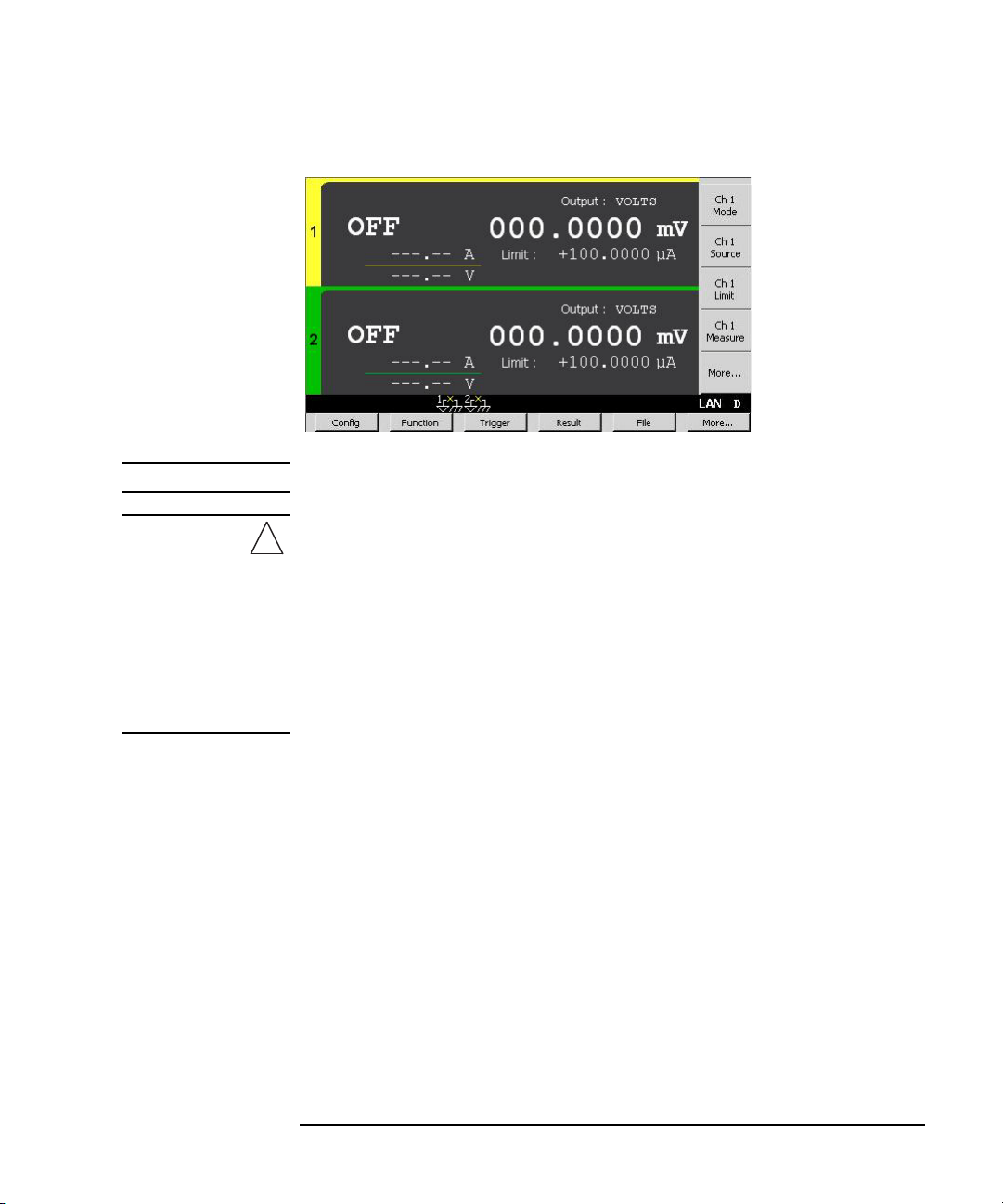
Installation
Connecting a DUT
Figure 3-4 Dual View, Floating Status for Channels 1 and 2
CAUTION Do not apply current to the chassis ground. Doing so will damage the instrument.
WARNING To prevent electrical shock, do not touch any of measurement circuit at any
time while a floating measurement is in progress. Also use accessories that
comply with IEC 6101 0-2-03 1. Al l termin als and th e extende d cond uctors must
be isolated by using insulation caps, sleeves, etc.
Afin d’éviter toute décharge électrique, ne touchez aucune mesure de circuit à
tout moment lorsque la mesure de flotte est en cours. Utiliser également des
accessoires qui sont conformes à la norme IEC 61010-2-031. Toutes les bornes
et les conducteurs prolongés doivent être isolés en utilisa nt des bouchons
d'isolation, des manchons, etc.
Keysight B2961A/B2962A User’s Guide, Edition 3 3- 17
Page 80

Installation
High Sense
High Force
Low Force
Low Sense
DUT
High Force
Low Force
DUT
2-wire connections
4-wire connections
Connecting a DUT
Using Test Leads
B2961A/B2962A source/measure terminals use banana jacks. For connecting a
DUT, the following test leads are available. Figure 3-5 shows the connections for
two-terminal device measurements.
• Keysight U8201A Combo Test Lead Kit
Couple of test leads, test probes, alligator clips, SMT grabbers, fine-tips test
probes, and banana plugs, CAT III 1000 V, 15 A maximum
Two kits are required for 4-wire connections.
• Keysight 110 59A Kelvin Probe Set
Test leads for 4-wire connections, 42 V maximum
Figure 3-5 Connect ing a Two-Term inal Device
3-18 Keysight B2961A/B2962A User’s Guide, Edition 3
Page 81

Installation
Connecting a DUT
Using the Low Noise Filter
The following filters are available for the B2961A/B2962A to apply low-noise and
clean output signal. See Figure 3-6 for their top and connector panels. Also see
“Output Filter and External Filter” on page 6-12 for more information.
• Keysight N1294A-020 High Current Ultra Low Noise Filter
Maximum voltage/current: 21 V / 500 mA (DC)
Output: BNC
• Keysight N1294A-021 Ultra Low Noise Filter
Maximum voltage/current: 42 V / 105 mA (DC)
Output: BNC
• Keysight N1294A-022 Low Noise Filter
Maximum voltage/current: 210 V / 3 A (DC)
Output: Banana
Preparation T o use the low noise filter, perform the following procedure. This setting is saved to
the non-volatile memory.
1. Press the Config > Source > Ext. Filter function keys. This opens the External
Output Filter dialog box.
2. Set the External Filter State field to ON.
3. Specify the type of the used filter on the External Filter Type field. Then press
one of the following assist keys.
HC-ULNF: High current ultra low noise filter (N1294A-020)
ULNF: Ultra low noise filter (N1294A-021)
LNF: Low noise filter (N1294A-022)
4. Press the OK softkey.
The following indicator appears on the Single view or the Dual view. And then
the filter can be connected to the output terminal.
: High current ultra low noise filter (N1294A-020)
: Ultra low noise filter (N1294A-021)
: Low noise filter (N1294A-022)
Keysight B2961A/B2962A User’s Guide, Edition 3 3- 19
Page 82

Installation
Connecting a DUT
Connections 1. Attach the filter tightly to the B2961A/B2962A source/measure terminals. Note
that the contact is not enough if the connection looks like “Bad connection”
shown in Figure 3-7.
2. Use appropriate cable or test leads to connect the output of the filter.
CAUTION Before connecting the filter, set External Filter State and External Filter Type
correctly. If the settings are correct, the B2961A/B2962A can limit the output up to
the filter’s maximum voltage/current. However, if the settings are wrong, the
B2961A/B2962A cannot limit the output and may damage the filter.
WARNING For using the floating condition, see “Floating” on page 3-16.
If the N1294A-020/021 ultra low noise filter is used, you can touch the outer
conductor of the output connector (BNC). Filter case is grounded. However, to
prevent electrical shock, cover over the outer conductor of BNC connector with
insulator.
Pour utiliser la condition de flottaison, reportez-vous à la section « Floating ».
Si le filtre N1294A-020/021 à ultra-faible bruit est utilisé, vous pouvez toucher
le conducteur externe du connecteur de sortie (BNC). Afin d'éviter toute
électrocution, recouvrez le conducteur externe avec de l'isolant.
3-20 Keysight B2961A/B2962A User’s Guide, Edition 3
Page 83

Figure 3-6 N1294A-020/021/022 Low Noise Filter
Output
±42V& Max, ± 105 mA Max
N1294A Opt 021
Ultra Low Noise Filter 42 V/105 mA
Push the adapter in firmly until it
locks in-place(< 1mm spacing)
± 42 V& Max
HSHS HF LF LS
Filter
Guard
N1294A Opt 022
Low Noise Filter 210 V/3 A
Push the adapter in firmly until it
locks in-place(< 1mm spacing)
± 250 V& Max
HS HFHS LF LS
Filter
Guard
±210 V&Max
High
Sense
High
Force
Low
Sense
Low
Force
Output
±21V& Max, ± 500 mA Max
N1294A Opt 020
HIgh Current Ultra Low Noise Filter
21 V/500 mA
Push the adapter in firmly until it
locks in-place(< 1mm spacing)
± 21 V& Max
HSHS HF LF LS
Guard
Filter
Installation
Connecting a DUT
Keysight B2961A/B2962A User’s Guide, Edition 3 3- 21
Page 84

Installation
Bad connection
Good connection (no space)
1
1
2
3
4
3
2
4
± 42V 1.05 A Max
Low Force
High Force
DUT
Connecting a DUT
Using the N1295A Test Fixture
Keysight N1295A is a test fixture which has four triaxial connectors and which
supports two 2-wire connections.
Requirements • Keysight N1295A test fixture furnished with pin clip wire 4 ea. and pin plug
wire 2 ea.
• Keysight N1294A-001 banana to triaxial adapter for 2-wire connections
• Triaxial cable, 2 ea. for one 2-wire connection
Connections 1. Attach the banana to triaxial adapter to the B2961A/B2962A source/measure
terminals. See Figure 3-7. If there is some space as “Bad connection”, the
contact is not enough.
2. Conn ect the triax ial cables b etween the adapter and N1295A as shown in Figure
3-8.
3. Connect the DUT between terminals 1 and 2 for the example in Figure 3-8.
Figure 3-7 Attaching Banana to Triaxial Adapter
Figure 3-8 Keysight N1295A Connection Example
NOTE Shielding
N1295A is equipped wit h a cover. To minimize the eff ect of ambient noise, clos e the
cover when performing measurements.
3-22 Keysight B2961A/B2962A User’s Guide, Edition 3
Page 85

Installation
Connecting a DUT
CAUTION Maximum voltage and current
The test fixture and adapters must be us ed under the follo wing limitation s to prevent
damage.
Keysight N1294A-001: 250 V maximum, 42 V maximum for connecting
N1295A
Keysight N1294A-002: 250 V maximum, 42 V maximum for connecting
N1295A
Keysight N1295A: 42 V, 1.05 A maximum
Using the 16442B Test Fixture
Keysight 16442B is a test fixture which has six triaxial connectors for
source/measure unit (SMU), the GNDU connector for the ground unit of a
parameter/device analyzer, the Intlk connector for the interlock control, and six
coaxial connectors for other instruments. See Keysight 16442B User’s Guide for
details and accessories of the 16442B.
Requirements • Keysight 16442B test fixture furnished with pin clip wire, pin plug wire, etc.
• Keysight N1294A-001 banana to triaxial adapter for 2-wire connections
• Keysight N1294A-002 banana to triaxial adapter for 4-wire connections
• Triaxial cable, 2 ea. for 2-wire connections, and 3 ea. for 4-wire connections
NOTE Shielding
16442B is equipped with a cover. To minimize the effect of ambient noise, clos e the
cover when performing measurements.
CAUTION Maximum voltage and current
The test fixture and adapters must be us ed under the follo wing limitation s to prevent
damage.
Keysight N1294A-001: 250 V maximum, 200 V maximum for connecting
16442B
Keysight N1294A-002: 250 V maximum, 200 V maximum for connecting
16442B
Keysight 16442B: 200 V, 1 A maximum for SMU input
Keysight B2961A/B2962A User’s Guide, Edition 3 3- 23
Page 86

Installation
N1294A-001 Adapter
for 2-wire connections
N1294A-002 Adapter
for 4-wire connections
to SMU 2
Force
to SMU 1 Force
to SMU 1 Force
to SMU 1 Sense
to SMU 3 Sense
(or GNDU)
Low Force/
Low Sense
High Sense
High Force
Low Force
High Force
SMU(±200V= 1A Max)
SenseForce
Guard Guard
1
SenseForce
Guard Guard
2
SenseForce
Guard Guard
3
DUT
SMU(±200V= 1A Max)
SenseForce
Guard Guard
1
SenseForce
Guard Guard
2
SenseForce
Guard Guard
3
2-wire connections
4-wire connections
DUT
(or GNDU Sense)
(or GNDU Force)
Connecting a DUT
Connections 1. Attach the banana to triaxial adapter to the B2961A/B2962A source/measure
terminals. See Figure 3-7. If there is some space as “Bad connection”, the
contact is not enough.
2. Connect the triaxial cables between the adapter and the 16442B. Figure 3-9
shows a connection example.
3. Connect the DUT on the 16442B wiring panel by using the 16442B’s furnished
accessories, socket module, blank board, and wire suitable for the DUT.
Figure 3-10 shows the connection example for the connections of Figure 3-9.
For 2-wire connections, connect the SMU 1 Force terminal to a DUT terminal,
and connect the SMU 2 Force terminal to the other DUT terminal.
For 4-wire connections, connect the SMU 1 Force and Sense terminals to a DUT
terminal. And connect the SMU 3 Sense and Guard terminals to the other DUT
terminal if the adapter’s Low Force/Low Sense connector is connected to the
SMU 3 Sense connector. The Low Force signal appears on the Guard terminal.
Figure 3-9 Connection Example between N1294A and 16442B
Figure 3-10 Connection Example of 16442B Wiring Panel
3-24 Keysight B2961A/B2962A User’s Guide, Edition 3
Page 87

Installation
Connecting a DUT
NOTE Performing high voltage measurement
When the Digital I/O interlock terminal is open, B2961A/B2962A cannot apply
high voltage over 42 V. T o perfo rm high vol tage measur ements , B29 61A/ B2 962 A
must be connected to the interlock circuit installed in 16442B.
Prepare the N1294A-011 or 012 interlock cable, and connect it between the
B2961A/B2962A Digital I/O connector and the 16442B Intlk connector.
B2961A/B2962A can apply a high voltage when the test fixture cover is closed.
WARNING Hazardous voltage, instrument maximum output voltage may appear at the
High Force, High Sense, and Guard terminals if the fixture cover is closed.
To prevent electrical shock, do not expose these lines.
Une tension dangereuse, une tension de sortie maximale de l'appareil peut
apparaître aux bornes High Force, High Sense et Guard si le couvercle de
l'équipement est fermé. Afin d’éviter toute décharge électrique, n’exposez pas
ces lignes.
Keysight B2961A/B2962A User’s Guide, Edition 3 3- 25
Page 88

Installation
A
Buffer
Guard
High Force
DUT
Connecting a DUT
Guarding
Guarding reduces the leakage current between the instrument and a DUT. This is
important when you measure a low current.
Figure 3-11 shows the theory of guarding. The buffer amplifier (1) keeps the
potential of the Guard conductor at the same potential as the High Force conductor,
so that the current does not flow between the High Force and Guard conductors.
Therefore, the current measured by the instrument is the same as the current at the
DUT terminal because no current is leaked.
For the connection examples shown in Figu res 3-8 and 3-9, the guard is extended to
the test fixture input connectors with triaxial cables.
Figure 3-11 Guarding
CAUTION Never connect the Guard terminal to any output, including circuit common, chassis
ground, or any other guard terminal. Doing so will damage the B2961A/B2962A.
3-26 Keysight B2961A/B2962A User’s Guide, Edition 3
Page 89

Installation
Mechanical switches
Shielding box
LED
Access door
D-sub connector
Interlock circuit
B2961A/B2962A
Digital I/O
15, 19
14
17, 18
16
24, 25
Dsub cable
15, 19
22, 23
16, 17
24
14
Negative
Positive
or
22
R
R: 500 Ω to 1 kΩ
25
R
Installing the Interlock Circuit
Installing the Interlock Circuit
The interlock circuit is a simple electric circuit, as shown in Figure 3-12. The circuit
electrically opens when an access door is opened, and closes when the door is
closed.
B2961A/B2962A cannot apply high voltages over 42 V when the Digital I/O
interlock terminal is open. To perform high voltage measurements, the
B2961A/B2962A interlock terminal must be connected to the interlock circuit
installed in the measurement environment such as the shielding box. The interlock
circuit is important and necessary to prevent electrical shock when the user touches
the measurement terminals.
WARNING Hazardous voltage, instrument maximum output voltage may appear at the
High Force, High Sense, and Guard terminals if the fixture cover is closed.
To prevent electrical shock, do not expose these lines.
Une tension dangereuse, une tension de sortie maximale de l'appareil peut
apparaître aux bornes High Force, High Sense et Guard si le couvercle de
l'équipement est fermé. Afin d’éviter toute décharge électrique, n’exposez pas
ces lignes.
Figure 3-12 Interlock Circuit
Requirements • LED (Keysight part number 1450-0641 or equivalent), 1 ea.
• Mechanical switch (Keysight N1254A-402 or equivalent), 2 ea.
• Resistor, 500 to 1 k (choose lower one to get higher output of LED), 1 ea.
Keysight B2961A/B2962A User’s Guide, Edition 3 3- 27
Page 90

Installation
Installing the Interlock Circuit
• 25-pin D-sub connector (for wiring, mounted on the shielding box), 1 ea.
• Connection wire
• 25-pin D-sub cable, 1 ea.
Procedure 1. Mount two mechanical switches onto your shielding box, so that the switches
close when the access door is closed, and open when the door is opened. See
Figure 3-14 for the switch dimensions.
2. Mount an LED onto your shielding box. See Figure 3-13 for the LED
dimensions.
The LED is used as a high voltage indicator which is lit when B2961A/B2962A
is in the high voltage output status.
3. Mount a D-sub connector onto your shielding box.
4. Use a wire and short the following pins of the D-sub connector. See Figure 3-12
for a connection example.
For the negative logic: Pins 24 and 25
For the positive logic: Pins 16 and 17
5. Use a wire and con nect the two switches in series be tween the following pins of
the D-sub connector. See Table 3-1 for the Digital I/O pin assignment.
For the negative logic: Pins 16 and some ground pins
The ground pins are pin numbers 15 and 17 to 21.
For the positive logic: Pins 24 and some +5 V pins
The +5 V pins are pin numbers 22, 23, and 25.
6. Use a wire and co nnect the LED between the pin 14 an d some ground pins o f the
D-sub connector. Then set the pin 14 to HIGH VOLTAGE LAMP. See “DIO
Configuration dialog box” on page 4-45.
7. Connect a resistor between the pin 14 and an unused +5 V pin.
3-28 Keysight B2961A/B2962A User’s Guide, Edition 3
Page 91

Installing the Interlock Circuit
6
10
11
5
5.6
5
Units: mm
Anode (+)
Cathode (-)
3.1
35.6
8.1
14
NC
NO
COM
6.4
22.2
27.8
2.8
6.3 15.9 18.8
4.7510.3 4.3
2.8
2.8
3.2
10.3
2.8
3.1
Switch off
Units: mm
15.3
Figure 3-13 Dimensions of the LED (Keysight part number 1450-0641)
Figure 3-14 Dimensions of the Interlock Switch (Keysight N1254A-402)
Installation
Keysight B2961A/B2962A User’s Guide, Edition 3 3- 29
Page 92

Installation
Connect to GPIB interface
card installed in PC.
Connect to GPIB
port on instrument.
InstrumentInstrument
Instrument
PC
GPIB cable
Connecting to the Interfaces
Connecting to the Interfaces
CAUTION Electrostatic discharges greater than 1 kV near the interface connectors may cause
the unit to reset and require operator intervention.
B2961A/B2962A supports GPIB, L AN, and USB interf aces. All thr ee interfaces are
live at power-on. Connect your interface cable to the appropriate interface
connector. Information on configuring the interfaces can be found later in this
section.
The front panel display’s LAN indicator is lit when the LAN port is connected and
configured.
B2961A/B2962A provides Ethernet connection monitoring. With Ethernet
connection monitoring, the instrument’s LAN port is continually monitored and
automatically reconfigured.
GPIB/USB Interfaces
NOTE For detailed information about GPIB and USB interface connections, refer to
Connectivity Guide installed with the Keysight IO Libraries.
The following steps will help you quickly get started connecting your instrument to
the GPIB (General Purpose Interface Bus). The following figure illustrates a typical
GPIB interface system.
3-30 Keysight B2961A/B2962A User’s Guide, Edition 3
Page 93

Installation
Connect to USB
port on PC.
Connect to USB
port on instrument.
Instrument
PC
USB cable
Connecting to the Interfaces
1. If you hav e not already done so, install the Keysi ght I O Librari es S uit e fro m the
CD shipped with your product.
2. If you do not have a GPIB interface card installed on your computer, turn off
your computer and install the GPIB card.
3. Connect your instrument to the GPIB interface card using a GPIB interface
cable.
4. Use the Connection Expert utility from the Keysight IO Libraries Suite to
configure the installed GPIB interface card’s parameters.
5. B2961A/B2962A is shipped with its GPIB address set to 23. To view or change
the GPIB address, press the More function key, then the I/O > GPIB softkeys.
The GPIB Configuration dialog box appears.
To change the GPIB address, use the rotary knob or the arrow keys, and press
OK to set the value.
6. You can now use the Interactive IO within Connection Expert to communicate
with your instrument, or program your instrument using various programming
environments.
The following steps will help you quickly get started with connecting your
USB-enabled instrument to the USB (Universal Serial Bus). The following figure
illustrates a typical USB interface system.
1. If you have n ot already done so, i nstall Key sight IO Libraries Suite from the CD
shipped with your product.
2. Conn ect the USB device port located on the back of your instrument to the USB
port on your computer.
3. With the Connection Expert utility from Keysight IO Libraries Suite running,
the computer will automatically recognize the instrument. This may take several
seconds. When the instrument is recognized, your computer will display the
VISA alias, IDN string, and VISA address.
Keysight B2961A/B2962A User’s Guide, Edition 3 3- 31
Page 94

Installation
To network
interface card (NIC).
Connect to LAN
port on instrument.
Instrument
PC
LAN cable
To site LAN
Connecting to the Interfaces
You can also view the instrument’s VISA address from the fro nt panel. Press the
More function key, then the I/O > USB softkeys. The VISA address is shown in
the USB Status dialog box.
4. You can now use the Interactive IO within Connection Expert to communicate
with your instrument, or program your instrument using various programming
environments.
LAN Interface
NOTE For detailed information about LAN interface connections, refer to Connectivity
Guide installed with the Keysight IO Libraries.
The following steps will help you quickly get started with connecting and
configuring your instrument on a local area network.
Connecting to a Site LAN
A site LAN is a local area network in which LAN-enabled instruments and
computers are connected to the network via routers, hubs, and/or s witches. They are
typically large, centrally-managed networks with services such as DHCP and DNS.
1. If you hav e not alread y done so, install the Keysight I O Li brarie s S uit e fro m t he
CD shipped with your product.
2. Connect the instrument to the site LAN. The factory-shipped instrument LAN
settings are configured to automatically obtain an IP address from the network
using DHCP (DHCP is enabled). Note that this may take up to one minute. The
DHCP server will register the instrument’s hostname with the dynamic DNS
server. The hos tname as well as the IP address can then be used to commu nicate
with the instrument. The front panel display’s LAN indicator will turn green
when the LAN port has been configured successfully, or turn red if the
configuration fails.
3-32 Keysight B2961A/B2962A User’s Guide, Edition 3
Page 95

Installation
Connecting to the Interfaces
NOTE If you need to manually configure any instrument LAN settings, see “LAN
Configuration dialog bo x” on page 4-45 for informat ion about conf igur ing the LAN
settings from the front panel of the instrument.
3. Use the Connection Expert utility from Keysight IO Libraries Suite to add the
B2961A/B2962A and verify the connection. To add the instrument, you can
request Connection Expert to discover the instrument. If the instrument canno t
be found, add the instrument using the instrument’s hostname or IP address.
NOTE If this does not work, refer to the troubleshooting section in Connectivity Guide.
4. You can now use the Interactive IO within Connection Expert to communicate
with your instrument, or program your instrument using various programming
environments. You can also use the W eb browser o n your compu ter to connect to
the instrument as described under “Using the Graphical Web Interface”.
Viewing the Active LAN Status
T o view the currently active LAN settings, press the More function key, then the I/O
> LAN > Status softkeys. The LAN status dialog box appears.
Note that the currently active LAN settings for the IP Address, Subnet Mask, and
Default Gateway may be different from the settings specified in the LAN
Configuration dialog box, depending on the configuration of the network. If the
settings are different, it is because the network has automatically assigned its own
settings.
Modifying the LAN Settings
As shipped from the factory, B2961A/B2962A’s pre-configured settings should
work in most LAN environments. If you need to manually configure these settings,
press the More function key, then the I/O > LAN > Config softkeys. The LAN
Configuration dialog box appears.
NOTE B2961A/B2962A must be rebooted if the host name is changed.
For the LAN setup parameters, see “LAN Configuration dialog box” on page 4-45.
Keysight B2961A/B2962A User’s Guide, Edition 3 3- 33
Page 96

Installation
B2961A
B2961A
Keysight B2961A Precision DC/AC Signal Source - MY00009001
B2961A
Communicating Over the LAN
Communicating Over the LAN
Using the Graphical Web Interface
Your Keysight B 296 1A/B2962A has a built-in graphical web interface that lets you
control it directly from an Web browser on your computer. Multiple simultaneous
connections are allowed, but only from one computer. With additional connections,
performance will be reduced. Multiple connections from multiple computers are not
allowed.
With the graphical web interface, you can access the front panel control functions
including the LAN configuration parameters. This is a convenient way to
communicate with the B2961A/B2962A without using I/O libraries or drivers.
NOTE The built-in graphical web interface only operates over the LAN interface. It
requires Internet Explorer 6+ or Firefox 2+. You will also need the Java Plug-in.
This is included in the Java Runtime Environment. Visit the Java’s website.
The graphical web interface is enabled when shipped.
3-34 Keysight B2961A/B2962A User’s Guide, Edition 3
Page 97

Installation
Communicating Over the LAN
To launch the graphical web interface:
1. Open a Web browser on your computer.
2. Enter the instrument’s hostname or IP address into the browser’s Address field
to launch the graphical web interface. The B2961A/B2962A home page will
appear.
3. Click on the Browser Web Control button in the navigation bar on the left to
begin controlling your instrument.
4. For additional help about any page, click “Help with this Page”.
If desired, you can control the access to the graphical web interface using password
protection. As shipped from th e factory, the password is set to keysight or agilent. To
change the password, click on the View & Modify Configuration button. Refer to
the online help for additional information about setting the password.
Using Telnet
The Telnet utility (as well as sockets), is another way to communicate with
B2961A/B2962A without using I/O libraries or drivers. In all cases, you must first
establish a LAN connection from your computer to the B2961A/B2962A as
previously described.
In an MS-DOS Command Prompt box, type “telnet hostname 5024” where
hostname is the B2961A/B2962A’s hostname or IP address, and 5024 is the
instrument’s telnet port. You should get a Telnet session box with a title indicating
that you are connected to the B2961A/B2962A. Type the SCPI commands at the
prompt.
Using Sockets
NOTE Keysight B2961A/B2 962 A allow s any combination of up to four simult aneou s dat a
socket, control socket, or telnet connections to be made.
Keysight instruments are standardized on using port 5025 for SCPI socket services.
A data socket on this port can be used to send and receive ASCII/SCPI commands,
queries, and query responses. All commands must be terminated with a newline for
the message to be parsed. All query responses will also be terminated with a
newline.
Keysight B2961A/B2962A User’s Guide, Edition 3 3- 35
Page 98

Installation
Communicating Over the LAN
The socket programming interface also allows control socket connections. The
control socket can be used by a client to send device clear and to receive service
requests. Unlike the data socket, which uses a fixed port number, the port number
for a control socket varies and must be obtained by sending the following SCPI
query to the data socket: SYSTem:COMMunicate:TCPip:CONTrol?
Once the port number is obtained, a control socket connection can be opened. As
with the data socket, all commands to the control socket must be terminated with a
newline, a nd all query responses returned on the control socket will be terminated
with a newline.
To send a device clear, send the string “DCL” to the control socket. When the
B2961A/B2962A has finished performing the device clear, it will echo the string
“DCL” back to the control socket.
Service requests are enabled for control sockets using the Service Request Enable
register. Once service requests have been enabled, the client program listens on the
control connection. When SRQ becomes true, the instrument will send the string
“SRQ +nn” to the client. The “nn” is the status byte value, which the client can use
to determine the source of the service request.
3-36 Keysight B2961A/B2962A User’s Guide, Edition 3
Page 99

Installation
Vcc
to Digital I/O
connector
R1
R2
from Output control
Vcc: +5 V
R1: 5 kohm
R2: 100 ohm
to Input control
Using Digital I/O
Using Digital I/O
B2961A/B2962A has a Digital I/O connector, D-sub 25 pin female, for general
purpose input/output (GPIO). It can be used for:
• Trigger input
• Trigger output
• Digital signal input/output
• Digital signal input
• Interlock control
• High voltage status output (shared with the digital signal input/output DIO 14)
The pin assignment of the Digital I/O connector is shown in Table 3-1. Pins DIO 1
to DIO 14 can be assigned to one of the above functions, except for interlock
control. T o set the DIO functions, press the More function key, then the I/O > DIO >
Config softkeys. For details, see “DIO Configuration dialog box” on page 4-45.
Figure 3-15 shows the input/output circuits internally connected to each pin of the
Digital I/O connector.
For the available accessory, see “Accessory for Digital I/O Connector” on page
3-39.
Figure 3-15 Digital I/O Internal Circuit
Keysight B2961A/B2962A User’s Guide, Edition 3 3- 37
Page 100

Installation
Using Digital I/O
Table 3-1 Di gital I/O Pin Assignment
Description Pin Number Description
a
+5 V
Interloc k control
a
+5 V
a
+5 V
b
25 13 DIO 13 (bit 13)
24 12 DIO 12 (bit 12)
23 11 DIO 11 (bit 11)
22 10 DIO 10 (bit 10)
GND 21 9 DIO 9 (bit 9)
GND 20 8 DIO 8 (bit 8)
GND 19 7 DIO 7 (bit 7)
GND 18 6 DIO 6 (bit 6)
GND 17 5 DIO 5 (bit 5)
Interlock control
c
16 4 DIO 4 (bit 4)
GND 15 3 DIO 3 (bit 3)
DIO 14 (bit 14) or
14 2 DIO 2 (bit 2)
High voltagestatus
1 DIO 1 (bit 1)
a. Current limit: 600 mA (total current to the pins 22, 23, and 25)
b. Used for the positive logic. Connected to the pin 25 for the negative
logic.
c. Used for the negative logic. Connected to the pin 17 for the positive
logic.
3-38 Keysight B2961A/B2962A User’s Guide, Edition 3
 Loading...