

Page 1

Keysight Technologies B1542A
Pulsed IV Package
for B1500A/EasyEXPERT
User’s Guide
Page 2

Notices
Copyright Notice
© Keysight Technologies 2006-2017
No part of this manual may be reproduced in
any form or by any means (including
electronic storage and retrieval or translation
into a foreign language) without prior
agreement and written consent from Keysight
Technologies as governed by United States
and international copyright laws.
Manual Part Number
B1542-90000
Edition
Edition 1, July 2006
Edition 2, September 2006
Edition 3, February 2007
Edition 4, June 2007
Edition 5, July 2008
Edition 6, October 2009
Edition 7, October 2011
Edition 8, February 2012
Edition 9, August 2014
Edition 10, February 2017
Printed in:
Printed in Malaysia
Published by:
Keysight Technologies International Japan
G.K.
9-1, Takakura-cho, Hachioji-shi, Tokyo
192-0033 Japan
Technology Licenses
The hardware and/or software described in
this document are furnished under a license
and may be used or copied only in accordance
with the terms of such license.
U.S. Government Rights
The Software is “commercial computer
software,” as defined by Federal Acquisition
Regulation (“FAR”) 2.101. Pursuant to FAR
12.212 and 27.405-3 and Department of
Defense FAR Supplement (“DFARS”)
227.7202, the U.S. government acquires
commercial computer software under the
same terms by which the software is
customarily provided to the public.
Accordingly, Keysight provides the Software
to U.S. government customers under its
standard commercial license, which is
embodied in its End User License Agreement
(EULA), a copy of which can be found at http:/
/www.keysight.com/find/sweula. The license
set forth in the EULA represents the exclusive
authority by which the U.S. government may
use, modify, distribute, or disclose the
Software. The EULA and the license set forth
therein, does not require or permit, among
other things, that Keysight: (1) Furnish
technical information related to commercial
computer software or commercial computer
software documentation that is not
customarily provided to the public; or (2)
Relinquish to, or otherwise provide, the
government rights in excess of these rights
customarily provided to the public to use,
modify, reproduce, release, perform, display,
or disclose commercial computer software or
commercial computer software
documentation. No additional government
requirements beyond those set forth in the
EULA shall apply, except to the extent that
those terms, rights, or licenses are explicitly
required from all providers of commercial
computer software pursuant to the FAR and
the DFARS and are set forth specifically in
writing elsewhere in the EULA. Keysight shall
be under no obligation to update, revise or
otherwise modify the Software. With respect
to any technical data as defined by FAR 2.101,
pursuant to FAR 12.211 and 27.404.2 and
DFARS 227.7102, the U.S. government
acquires no greater than Limited Rights as
defined in FAR 27.401 or DFAR 227.7103-5
(c), as applicable in any technical data.
Warranty
THE MATERIAL CONTAINED IN THIS
DOCUMENT IS PROVIDED “AS IS,” AND IS
SUBJECT TO BEING CHANGED, WITHOUT
NOTICE, IN FUTURE EDITIONS. FURTHER, TO
THE MAXIMUM EXTENT PERMITTED BY
APPLICABLE LAW, KEYSIGHT DISCLAIMS ALL
WARRANTIES, EITHER EXPRESS OR IMPLIED,
WITH REGARD TO THIS MANUAL AND ANY
INFORMATION CONTAINED HEREIN,
INCLUDING BUT NOT LIMITED TO THE
IMPLIED WARRANTIES OF
MERCHANTABILITY AND FITNESS FOR A
PARTICULAR PURPOSE. KEYSIGHT SHALL
NOT BE LIABLE FOR ERRORS OR FOR
INCIDENTAL OR CONSEQUENTIAL DAMAGES
IN CONNECTION WITH THE FURNISHING,
USE, OR PERFORMANCE OF THIS
DOCUMENT OR OF ANY INFORMATION
CONTAINED HEREIN. SHOULD KEYSIGHT
AND THE USER HAVE A SEPARATE WRITTEN
AGREEMENT WITH WARRANTY TERMS
COVERING THE MATERIAL IN THIS
DOCUMENT THAT CONFLICT WITH THESE
TERMS, THE WARRANTY TERMS IN THE
SEPARATE AGREEMENT SHALL CONTROL.
Declaration of Conformity
Declarations of Conformity for this product
and for other Keysight products may be
downloaded from the Web. Go to http://
www.keysight.com/go/conformity. You can
then search by product number to find the
latest Declaration of Conformity.
Latest Information
To get the latest firmware/software/electronic
manuals/specifications/support information,
go to www.keysight.com and type in the
product number in the Search field at the top
of the page.
Page 3

This product complies with the WEEE Directive (2002/96/EC) marking requirements. The
affixed label indicates that you must not discard this electrical/ electronic product in
domestic household waste.
Product Category: With reference to the equipment types in the WEEE Directive Annex I,
this product is classed as a “Monitoring and Control instrumentation” product.
Do not dispose in domestic household waste.
To return unwanted products, contact your local Keysight office or visit the following
website for more information.
http://about.keysight.com/en/companyinfo/environment/
Page 4

In This Manual
This manual provides the information about Keysight Technologies B1542A
and consists of the following chapters.
• Chapter 1, Introduction
Describes product overview of Keysight B1542A.
• Chapter 2, Installation
Explains how to install Keysight B1542A.
• Chapter 3, Performing System Setup and Compensation
Explains how to perform system setup and how to update compensation
data.
• Chapter 4, Performing Measurement
Describes measurement examples by using the pulsed IV test system.
• Chapter 5, PLSDIV Test Definitions
Provides reference information for application test definitions (PLSDIV
test definitions) used for the pulsed IV measurement.
• Chapter 6, PLSDIV TIS Commands
Provides reference information for execution files (Plsdiv commands,
PLSDIV TIS) used in the PLSDIV test definitions.
• Chapter 7, Status Code and Error Messages
Lists the status code and the error messages.
NOTE The pulsed IV test system consists of some instruments, oscilloscope, pulse
generator, source monitor unit, and so on. To use the instruments
independently or for details of the instruments, see the manual of each
instrument.
NOTE To get the latest firmware/software/manual/support information, go to
www.keysight.com and type in B1542A in the Search field at the top of the
page.
Page 5

Contents
1. Introduction
Overview. . . . . . . . . . . . . . . . . . . . . . . . . . . . . . . . . . . . . . . . . . . . . . . . . . . . 1-3
System Hardware . . . . . . . . . . . . . . . . . . . . . . . . . . . . . . . . . . . . . . . . . . . 1-3
System Software. . . . . . . . . . . . . . . . . . . . . . . . . . . . . . . . . . . . . . . . . . . . 1-5
Typical Technical Information . . . . . . . . . . . . . . . . . . . . . . . . . . . . . . . . . . . 1-6
Accessories and Options . . . . . . . . . . . . . . . . . . . . . . . . . . . . . . . . . . . . . . . 1-7
2. Installation
Inspection. . . . . . . . . . . . . . . . . . . . . . . . . . . . . . . . . . . . . . . . . . . . . . . . . . . 2-3
RF Probes . . . . . . . . . . . . . . . . . . . . . . . . . . . . . . . . . . . . . . . . . . . . . . . . . . . 2-4
DC Probes. . . . . . . . . . . . . . . . . . . . . . . . . . . . . . . . . . . . . . . . . . . . . . . . . . . 2-5
Hardware Installation . . . . . . . . . . . . . . . . . . . . . . . . . . . . . . . . . . . . . . . . . 2-6
Installing Instruments. . . . . . . . . . . . . . . . . . . . . . . . . . . . . . . . . . . . . . . . 2-6
Connecting Interface Cables . . . . . . . . . . . . . . . . . . . . . . . . . . . . . . . . . . 2-7
Installing Pulsed IV Test System . . . . . . . . . . . . . . . . . . . . . . . . . . . . . . . 2-8
Connecting RF Probes . . . . . . . . . . . . . . . . . . . . . . . . . . . . . . . . . . . . . . 2-13
Connecting DC Probes . . . . . . . . . . . . . . . . . . . . . . . . . . . . . . . . . . . . . . 2-14
Software Installation . . . . . . . . . . . . . . . . . . . . . . . . . . . . . . . . . . . . . . . . . 2-16
System Requirements . . . . . . . . . . . . . . . . . . . . . . . . . . . . . . . . . . . . . . 2-17
Installing Software . . . . . . . . . . . . . . . . . . . . . . . . . . . . . . . . . . . . . . . . . 2-17
Installing Cable Compensation Data . . . . . . . . . . . . . . . . . . . . . . . . . . . 2-17
After Software Installation . . . . . . . . . . . . . . . . . . . . . . . . . . . . . . . . . . . 2-18
Updating Software . . . . . . . . . . . . . . . . . . . . . . . . . . . . . . . . . . . . . . . . . 2-19
Removing Pulsed IV Software . . . . . . . . . . . . . . . . . . . . . . . . . . . . . . . . 2-19
Rack-mounting Instruments . . . . . . . . . . . . . . . . . . . . . . . . . . . . . . . . . . . 2-20
Rack-mounting Pulse/dc Switch Units . . . . . . . . . . . . . . . . . . . . . . . . . 2-21
3. Performing System Setup and Compensation
Page 6

Pulsed IV System Setup . . . . . . . . . . . . . . . . . . . . . . . . . . . . . . . . . . . . . . . . 3-3
Starting System Setup . . . . . . . . . . . . . . . . . . . . . . . . . . . . . . . . . . . . . . . . . 3-6
If You Use DSO/MSO 9000 Series or S Series Oscilloscope . . . . . . . . . . 3-7
If You Use External Computer . . . . . . . . . . . . . . . . . . . . . . . . . . . . . . . . . . 3-8
System Configuration . . . . . . . . . . . . . . . . . . . . . . . . . . . . . . . . . . . . . . . . . 3-10
LAN Setup for DSO Control Dialog Box . . . . . . . . . . . . . . . . . . . . . . . . . 3-10
SMU CH for Compensation Dialog Box. . . . . . . . . . . . . . . . . . . . . . . . . . 3-11
Executing Action . . . . . . . . . . . . . . . . . . . . . . . . . . . . . . . . . . . . . . . . . . . . . 3-12
Compensation Action . . . . . . . . . . . . . . . . . . . . . . . . . . . . . . . . . . . . . . . 3-13
Pgu Compensation Action . . . . . . . . . . . . . . . . . . . . . . . . . . . . . . . . . . . . 3-13
4. Performing Measurement
Theory of Measurement . . . . . . . . . . . . . . . . . . . . . . . . . . . . . . . . . . . . . . . . 4-3
Terminal Voltage and Source Output Value . . . . . . . . . . . . . . . . . . . . . . . 4-4
Before Measurement. . . . . . . . . . . . . . . . . . . . . . . . . . . . . . . . . . . . . . . . . . . 4-5
Performing System Reset . . . . . . . . . . . . . . . . . . . . . . . . . . . . . . . . . . . . . . . 4-6
Pulse Waveform Measurement . . . . . . . . . . . . . . . . . . . . . . . . . . . . . . . . . . 4-7
Pulsed Id-Vd Measurement . . . . . . . . . . . . . . . . . . . . . . . . . . . . . . . . . . . . . 4-9
Pulsed Id-Vg Measurement . . . . . . . . . . . . . . . . . . . . . . . . . . . . . . . . . . . . 4-11
DC I-V Measurements. . . . . . . . . . . . . . . . . . . . . . . . . . . . . . . . . . . . . . . . . 4-13
5. PLSDIV Test Definitions
PLSDIV Capt Wave . . . . . . . . . . . . . . . . . . . . . . . . . . . . . . . . . . . . . . . . . . . . 5-4
PLSDIV DC IdVd . . . . . . . . . . . . . . . . . . . . . . . . . . . . . . . . . . . . . . . . . . . . . . 5-7
PLSDIV DC IdVd SMU . . . . . . . . . . . . . . . . . . . . . . . . . . . . . . . . . . . . . . . . . 5-10
PLSDIV DC IdVg . . . . . . . . . . . . . . . . . . . . . . . . . . . . . . . . . . . . . . . . . . . . . 5-13
Page 7

PLSDIV DC IdVg SMU. . . . . . . . . . . . . . . . . . . . . . . . . . . . . . . . . . . . . . . . . 5-16
PLSDIV IdVd, PLSDIV IdVd [2] . . . . . . . . . . . . . . . . . . . . . . . . . . . . . . . . . . 5-19
PLSDIV IdVg, PLSDIV IdVg [2] . . . . . . . . . . . . . . . . . . . . . . . . . . . . . . . . . . 5-23
PLSDIV IV SMU . . . . . . . . . . . . . . . . . . . . . . . . . . . . . . . . . . . . . . . . . . . . . 5-27
PLSDIV Reset . . . . . . . . . . . . . . . . . . . . . . . . . . . . . . . . . . . . . . . . . . . . . . . 5-31
PLSDIV Setup . . . . . . . . . . . . . . . . . . . . . . . . . . . . . . . . . . . . . . . . . . . . . . . 5-32
Parameters . . . . . . . . . . . . . . . . . . . . . . . . . . . . . . . . . . . . . . . . . . . . . . . . . 5-34
6. PLSDIV TIS Commands
Command Summary . . . . . . . . . . . . . . . . . . . . . . . . . . . . . . . . . . . . . . . . . . 6-3
Entering Plsdiv Commands . . . . . . . . . . . . . . . . . . . . . . . . . . . . . . . . . . . . . 6-5
Command Parameters . . . . . . . . . . . . . . . . . . . . . . . . . . . . . . . . . . . . . . . 6-5
Defining Numeric/Vector Input Parameter . . . . . . . . . . . . . . . . . . . . . . . 6-6
Defining String/Numeric Input Parameters . . . . . . . . . . . . . . . . . . . . . . . 6-6
Defining Numeric Output Parameter . . . . . . . . . . . . . . . . . . . . . . . . . . . . 6-6
Defining Vector Output Parameter. . . . . . . . . . . . . . . . . . . . . . . . . . . . . . 6-7
Defining String Output Parameter . . . . . . . . . . . . . . . . . . . . . . . . . . . . . . 6-7
Defining Format Field . . . . . . . . . . . . . . . . . . . . . . . . . . . . . . . . . . . . . . . . 6-7
Setup Example . . . . . . . . . . . . . . . . . . . . . . . . . . . . . . . . . . . . . . . . . . . . . 6-8
Command Reference . . . . . . . . . . . . . . . . . . . . . . . . . . . . . . . . . . . . . . . . . 6-9
DispMessage. . . . . . . . . . . . . . . . . . . . . . . . . . . . . . . . . . . . . . . . . . . . . . 6-10
PlsdivCaptureMonData . . . . . . . . . . . . . . . . . . . . . . . . . . . . . . . . . . . . . 6-11
PlsdivCaptureTimeData . . . . . . . . . . . . . . . . . . . . . . . . . . . . . . . . . . . . . 6-12
PlsdivCutoffVd . . . . . . . . . . . . . . . . . . . . . . . . . . . . . . . . . . . . . . . . . . . . 6-13
PlsdivCutoffVg . . . . . . . . . . . . . . . . . . . . . . . . . . . . . . . . . . . . . . . . . . . . 6-13
PlsdivErrorMessage . . . . . . . . . . . . . . . . . . . . . . . . . . . . . . . . . . . . . . . . 6-13
PlsdivForceVd . . . . . . . . . . . . . . . . . . . . . . . . . . . . . . . . . . . . . . . . . . . . . 6-14
PlsdivForceVg . . . . . . . . . . . . . . . . . . . . . . . . . . . . . . . . . . . . . . . . . . . . . 6-14
Page 8

PlsdivInit . . . . . . . . . . . . . . . . . . . . . . . . . . . . . . . . . . . . . . . . . . . . . . . . . 6-15
PlsdivMeasureId . . . . . . . . . . . . . . . . . . . . . . . . . . . . . . . . . . . . . . . . . . . 6-17
PlsdivSetAdjustStat . . . . . . . . . . . . . . . . . . . . . . . . . . . . . . . . . . . . . . . . 6-18
PlsdivSetAveraging . . . . . . . . . . . . . . . . . . . . . . . . . . . . . . . . . . . . . . . . . 6-18
PlsdivSetDeviceDelay . . . . . . . . . . . . . . . . . . . . . . . . . . . . . . . . . . . . . . . 6-19
PlsdivSetMeasTime . . . . . . . . . . . . . . . . . . . . . . . . . . . . . . . . . . . . . . . . . 6-20
PlsdivSetPulseWid th . . . . . . . . . . . . . . . . . . . . . . . . . . . . . . . . . . . . . . . 6-21
PlsdivSetSampling . . . . . . . . . . . . . . . . . . . . . . . . . . . . . . . . . . . . . . . . . 6-21
PlsdivSetSmoothing . . . . . . . . . . . . . . . . . . . . . . . . . . . . . . . . . . . . . . . . 6-22
PlsdivSetTransTime . . . . . . . . . . . . . . . . . . . . . . . . . . . . . . . . . . . . . . . . . 6-23
PlsdivSetVgLevel . . . . . . . . . . . . . . . . . . . . . . . . . . . . . . . . . . . . . . . . . . . 6-23
PlsdivUninit . . . . . . . . . . . . . . . . . . . . . . . . . . . . . . . . . . . . . . . . . . . . . . . 6-24
7. Status Code and Error Messages
Page 9

1Introduction
Page 10

Introduction
Keysight B1542A Pulsed IV Package for B15 00/Eas yEXP ERT is a soluti on
package for the Keysight B1500A or Desk top Easy EX PERT users and pro vides the
automated pulsed IV test environment. This chapter introduces Keysight B1542A,
and consists of the following sections.
• “Overview”
• “Typical Technical Information”
• “Accessories and Options”
1-2 Keysight B1542A User’s Guide, Edition 10
Page 11

Introduction
Overview
Overview
Keysight B1542A Pulsed IV Package expands the capabilities of Keysight B1500A
Semiconductor Device Analyzer to enable the ultra short pulsed IV measurements
with parametric characterization down to 10 ns pulse width for many new device
structures such as silicon-on-insulator (SOI) transistors that are more susceptible to
harmful thermal effects during characterization.
Using the B1542A, you can easily and effectively configure the pulsed IV test
system and perform the pulsed IV measurement of MOSFET on the Keysight
EasyEXPERT or Desktop EasyEXPERT application test environment.
The B1542A supports the B1500A as the DC source monitor. And the B1542A
additionally supports the Keysight 4155B/4155C/4156B/4156C Semiconductor
Parameter Analyzer and the Keysight E5260/E5270 Series of Parametric
Measurement Solutions by using the Desktop EasyEXPERT software.
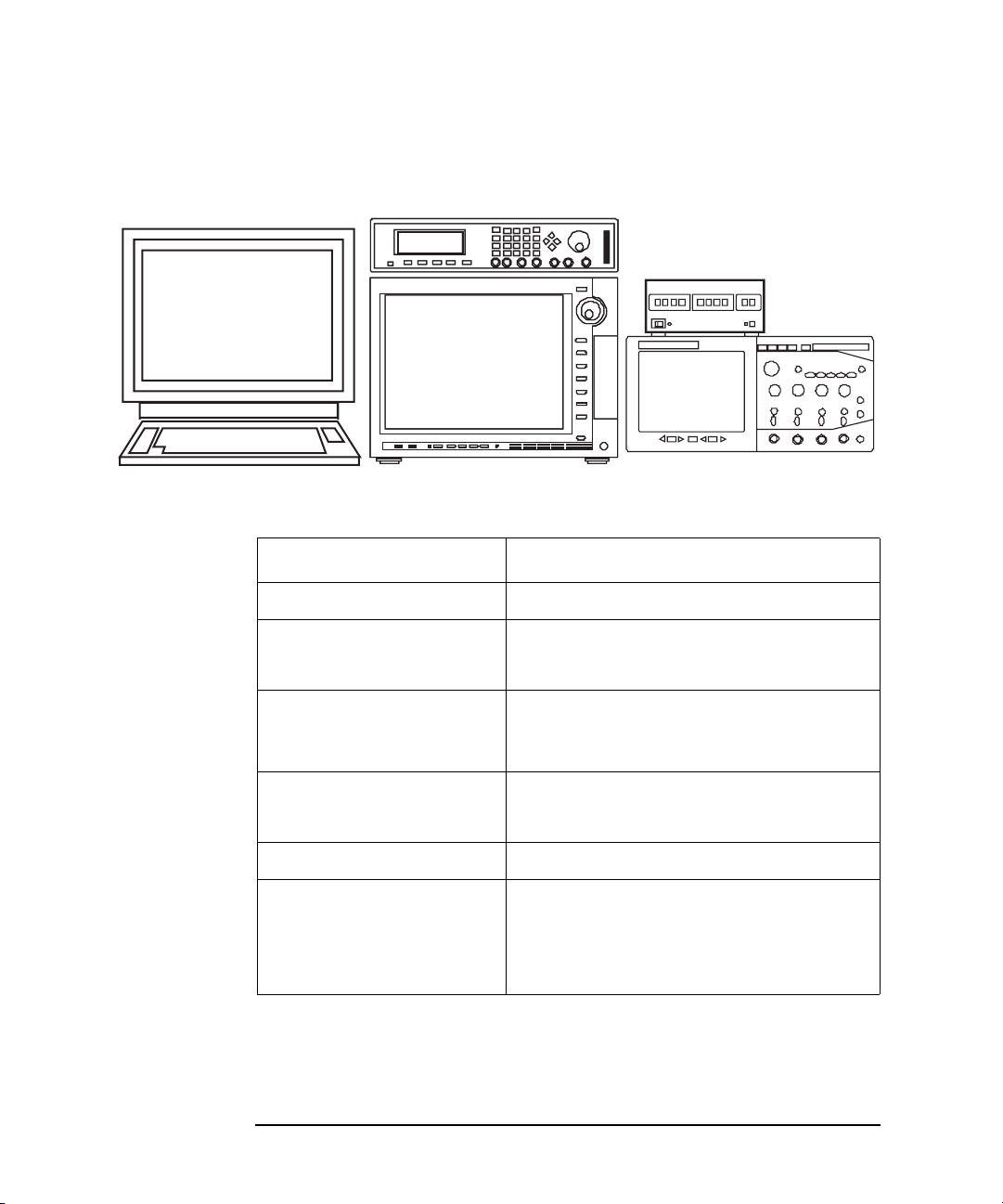
System Hardware
The pulsed IV test system can be configured by u sing the fo llowing equ ipment. See
Figure 1-1. The B1542A provides the accessories used to connect the equipment.
• Keysight B1500A Semiconductor Device Analyzer
• Oscilloscope, minimum two measurement channels, see Table 1-1
• Pulse Generator, minimum one output channel, see Table 1-2
• Switch Controller and Pulse/dc Switch Units, furnished with the B1542A
• Windows PC installed with Desktop EasyEXPERT
Optional for the system with the B1500A. Absolute necessity for the system
with the following instrument.
• Keysight 4155B/C Semiconductor Parameter Analyzer
• Keysight 4156B/C Precision Semiconductor Parameter Analyzer
• Keysight E5260A/E5270B Measurement Mainframe
The pulsed IV system uses 3 channels of SMU. So Keysight E5262A/E5263A
2-channel SMU is not recommended. However it may be used if you change the
connections manually. Because the pulsed IV measurement uses one SMU and the
DC IV measurement uses only 2 ea. of SMU.
Keysight B1542A User’s Guide, Edition 10 1-3
Page 12
Introduction
Oscilloscope
Pulse Generator
Switch Cont roller
Desktop EasyEXPERT
Windows PC
DC Source Monitor
(optional with B1500A)
Overview
Figure 1-1 Pulsed IV Test System by Using Keysight B1542A
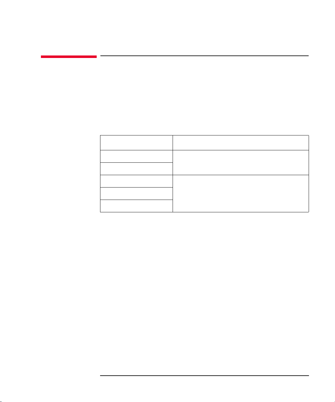
Table 1-1 Oscilloscope Supported by Keysight B1542A
Keysight Model Number Remarks
54853A/54854A/54855A 2.5/4/6 GHz, 4 channels, 20 GSa/s
DSO8000A series
MSO8000A series
DSO80000B series 2/3/4/6/8/10/12/13 GHz, 4 channels, 40 GSa/s
DSO9104A/9254A/9404A
MSO9104A/9254A/9404A
DSO90254A/90404A/90604A 2.5/4/6 GHz, 4 channels, 20 GSa/s
DSOS104A/S204A/S254A
DSOS404A/S604A/S804A
MSOS104A/S204A/S254A
MSOS404A/S604A/S804A
600 MHz or 1 GHz, 4 channels, 4 GSa/s
when using 1 or 2 channels, 20 GSa/s when
using all channels
1/2.5/4 GHz, 4 channels, 20 GSa/s
1/2/2.5/4/6/8 GHz, 4 channels, 20 GSa/s
DSO/MSO S series oscilloscope is supported
as DSO=DSO9000A series. See Table 3-3.
1-4 Keysight B1542A User’s Guide, Edition 10
Page 13

Table 1-2 Pulse Generator Supported by Keysight B1542A
Keysight Model Number Remarks
81101A 50 MHz output, standalone
8110A with 81103A 150 MHz output, modular
81110A with 81111A 165 MHz output, modular
81150A 120 MHz output, standalone
System Software
The B1542A supports the pulsed IV measurement applications listed below. The
programs used to perform the measurement are provided as the EasyEXPERT
application test definition. Therefore the pulsed IV measurement can be performed
easily on the EasyEXPERT or Desktop EasyEXPERT application test environment
without creating the test programs. The B1542A also provides the test definition
used for the system setup.
• Pulsed IV Id-Vd characteristics measurement
Introduction
Overview
• Pulsed IV Id-Vg characteristics measurement
• Pulsed IV waveform measurement
• DC Id-Vd characteristics measurement for B1500A
• DC Id-Vg characteristics measurement for B1500A
• Pulsed IV system reset
• Pulsed IV system setup
• DC I-V sweep measurement for 4155/4156/E5260/E5270
• DC Id-Vd characteristics measurement for 4155/4156/E5260/E5270
• DC Id-Vg characteristics measurement for 4155/4156/E5260/E5270
Keysight B1542A User’s Guide, Edition 10 1-5
Page 14

Introduction
Typical Technical Information
Typical Technical Information
The followings are the typical technical information of the pulsed IV test system
configured by Keysight B154 2A. Those are not the specifi cations but the typical and
supplemental data the test system can provide.
Gate pulse width: 10 ns to 1 s
Gate pulse voltage: -4.5 V to 4.5 V
Gate pulse base line voltage: -3.0 V to 3.0 V
Gate pulse amplitude: maximum 4.5 V
Gate pulse period: 100 s
Drain pulse maximum measurement current: 80 mA
Drain pulse current measurement resolution: 1 A
Drain voltage range: -10 V to 10 V
1-6 Keysight B1542A User’s Guide, Edition 10
Page 15

Accessories and Options
Table 1-3 li sts the available options for Keysight B1542A. And Table 1-4 lists the
contents of the B1542A.
Table 1-3 Options
Introduction
Accessories and Options
Model
Number
R1280A Return-to-Keysight - warranty and service plan
R1282A Return-to-Keysight calibration plan
Table 1-4 Contents
Software license to use, media, and manual
Pulsed IV package software CD-ROM 1
Drain cable compensation data CD-ROM 1
Desktop EasyEX PERT software CD-ROM 1
User’s Guide, English 1
Drain cable set
Triaxial cable, 1.5 m 1
BNC(m)-Triax(f) adapter, floating guard 1
SMA(f)-BNC(m) adapter, precision type 1
Description
Description Quantity
SMA cable, 30 cm 1
DUT cable, 1.5 m 1
Magnet sheet (for fixing the bias-T) 1
Keysight B1542A User’s Guide, Edition 10 1-7
Page 16

Introduction
Accessories and Options
Description Quantity
Gate cable set
SMA(f)-BNC(m) adapter 1
SMA cable, 30 cm 1
SMA(f)-BNC(m) adapter, precision type 1
SMA cable, 1.5 m 1
DUT cable, 1.5 m 1
SMA (f)-(m)-(f) adapter 1
Terminator, dc-26.5 GHz, 3.5 m with option 011 1
SMA(m)-SMA(m) adapter 1
Magnet sheet (for fixing the divider) 1
Docking interface
BNC cable, 1.5 m 2
Triaxial cable, 1.5 m 1
GNDU-chassis adapter 1
Triaxial cable, 1.5 m 1
BNC(m)-(f)-(f) adapter 1
BNC(m)-Triax(f) adapter, floating guard 1
GPIB cable, 1 m 2
Torque wrench, 5 lb. 1
Torque wrench, 8 lb. 1
Open-end wrench, 5/16 inch 1
Open-end wrench, 11/32 inch 1
1-8 Keysight B1542A User’s Guide, Edition 10
Page 17
Accessories and Options
Description Quantity
Pulse/dc switch set
Switch controller 1
Switch control cable (viking cable, D-sub 15 pin) 1
Switch control distributor 1
Drain pulse/dc switch unit 1
Gate pulse/dc switch unit 1
Triaxial cable, 1.5 m 2
D-sub 9 pin cable, 3 m 2
Wrench, T10 1
GPIB cable, 1 m 1
Rack-mount kit for pulse/dc switch units
Panel 1
Introduction
Rail kit for pulse/dc switch units 1
Rail kit for pulse/dc switch units 1
Support rail for rack-mounting oscilloscope (7 EIA maximum)
onto Keysight 1181B testmobile system cart
Screw 12
Screw 2
Nut 8
Wire 3
Screw 8
Pulsed IV DC probe cable set
SMA(f)-SSMC cable 1
SMA(m)-SSMC cable 1
SSMC short-open cable, 50 mm 2
SSMC short-open cable, 75 mm 2
Keysight B1542A User’s Guide, Edition 10 1-9
2
Page 18

Introduction
Accessories and Options
1-10 Keysight B1542A User’s Guide, Edition 10
Page 19

2 Installation
Page 20

Installation
This chapter describes the inspection and installation instructions of Keysight
B1542A pulsed IV package for B1500A/EasyEXPERT, and consists of the following sections. To perform the pulsed IV measurement, complete the hardware and
software installation described in this chapter.
• “Inspection”
• “RF Probes”
• “DC Probes”
• “Hardware Installation”
• “Software Installation”
• “Rack-mounting Instruments”
If you rack-mount the pulse/dc switch units, see “Rack-mounting Instruments” on
page 2-20 which describes how to install the rack-mount kit for the pulse/dc switch
units. After you complete the rack-mounting, see “Hardware Installation” on page
2-6 to install the system equipment.
CAUTION Using Torque Wrench and Open-end Wrench
For the RF measurements, it is important to carefully contact and fasten the
connectors of the RF cables. The condition of the cable connections may change the
measurement result characteristics. Therefore treat the RF cables carefully,
especially the RF connectors, and use the torque wrench and the open-end wrench
when you fasten the RF connectors. The wrenches are furnished with the B1542A.
CAUTION Using Cable Tie
Use a cable tie to secure the cables. Then, do not tug the cable tie. You must treat the
RF cables carefully to avoid the damage.
NOTE Using Magnet Sheet
Use a magnet sheet to fix the di vider or th e bias-T to a metal plate. The m agnet sheet
is furnished with the B1542A.
2-2 Keysight B1542A User’s Guide, Edition 10
Page 21

Installation
Inspection
Inspection
Perform the following inspections when the B1542A arrives at your site.
1. Before unpacking any components , inspect all boxes for any sign of damage that
might have occurred during shipment, such as:
•dents
• scratches
•cuts
• water marks
If you suspect any damage, notify your local Keysight Technologies sales or
service office.
2. When you open the boxes containing the B1542A, check the components
against the contents lists attached to the boxes. See also Table 1-4.
If anything is missing, notify your local Keysight Technologies sales or service
office.
Keysight B1542A User’s Guide, Edition 10 2-3
Page 22

Installation
Terminator
SMA- Tee
SMA(m) -(m)
To drain
To gate
RF probe
RF probe
Signal
Gnd
Gnd
Signal
Gnd
Gnd
Gate
Dra in
RF probe
RF probe
Source/Well
Source/Well
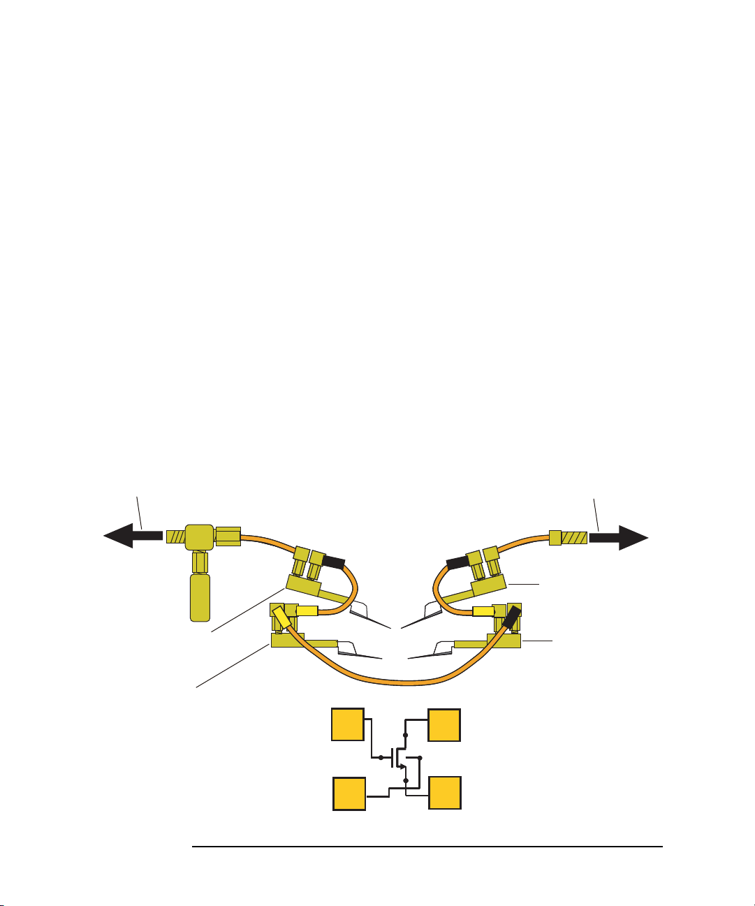
RF Probes
RF Probes
The pulsed IV test system supports the measurement of the three-terminal MOSFET
(source and well (substrate) are shorted). And its measurement path must be
extended to the RF probes as shown in Figure 2-1 to achieve 10 ns minimum pulse
width. One measurement path is for the gate terminal and the other path is for the
drain terminal. Moreover the source/well terminal must be electrically connected to
the ground via the shielding of the measurement path (RF probes and measurement
cables). See Figure 2-2.
Figure 2-1 RF Probe Connection
Prepare two RF probes to perform the pulsed IV measurement. The RF probe must
have the signal line and the grou nd lines as shown in Figure 2-2 . The signal line is to
contact the gate or drain pad, and the ground lines are to contact the source/well
pads. For the RF probe and its installation, consult your favorite prober vender.
Figure 2-1 shows the RF probes of Cascade Microtech, Inc.
Figure 2-2 Contact Pad and Probe Tip
2-4 Keysight B1542A User’s Guide, Edition 10
Page 23

DC Probes
Terminator
Well
Gate
Source
Drain
This makes a current return path
for the drain current signal.
This makes a current return path
for the gate pulse signal.
This shorts Well and Source.
to Test system
to Test system
DC probes
DC probes
Signal
Signal
Gnd
Gnd
The MOSFET contact pads for DC measurement shown in Figure 2-3, are more
popular than the RF contact pads shown in Figure 2-2. If device under test is
configured with DC contact pads, use DC probes instead of RF probes. The DC
probes are better suited for contact with the DC contact pads than the RF probes.
See Figure 2-3 for the contact pads and the DC probes. Required cables for
connecting the DC probes ar e furnish ed with the B154 2A as the D C probe cable s et.
For more information, see “Connecting DC Probes” on page 2-14.
When using DC probes, minimum pulse width should be limited to approximately
60 ns to 100 ns.
Figure 2-3 Contact Pad and DC Probe Connection
Installation
DC Probes
Keysight B1542A User’s Guide, Edition 10 2-5
Page 24
Installation
Oscilloscope
Pulse generator
Switch controller
DC source monitor
Hard ware Installation
Hardware Installation
This section describes the instructions to install the B1542A. The installation
instructions cover the connection of the control cables and the connection of the
measurement cables to the RF or DC probes used to contact the device under test
(MOSFET). The connection overview of the pulsed IV test system i s shown in
Figure 2-5.
• “Installing Instruments”
• “Connecting Interface Cables”
• “Installing Pulsed IV Test System”
• “Connecting RF Probes”
• “Connecting DC Probes”
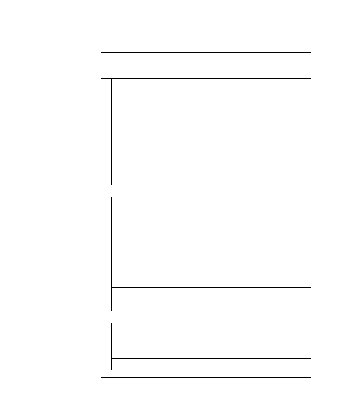
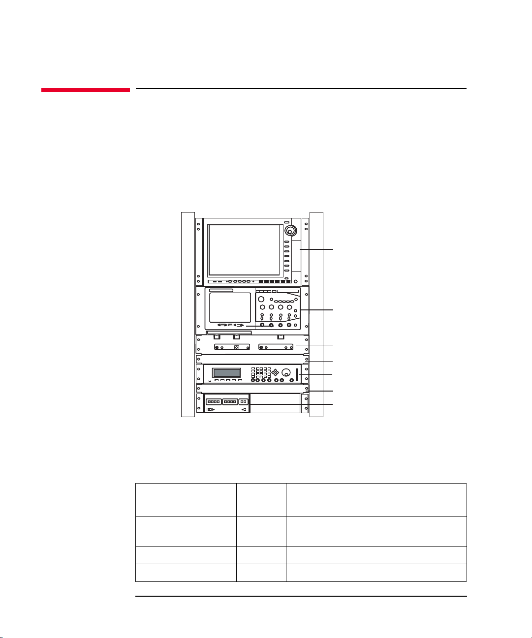
Installing Instruments
The pulsed IV test system uses the DC source monitor, pulse generator,
oscilloscope, and switch controller with switch units. Install the instruments to the
appropriate place. See Figure 2-4 for example. For more information, see the
manual of each instrument. It provides the required environment and the necessary
and unique information for the instrument.
Figure 2-4 Installing Instruments
2-6 Keysight B1542A User’s Guide, Edition 10
Page 25

Installation
Hard ware Installation
Connecting Interface Cables
Connect the instruments via GPIB or LAN as shown below.
Requirements:
• GPIB cable, maximum 4 ea. Quantity depends on your system components
(instruments and computer).
• LAN cable, 2 ea. only for using the DSO/MSO 9000 series or S series
oscilloscope
Procedure:
1. Connect a GPIB cable between the DC source monitor and the pulse generator.
2. Connect a GPIB cable between the switch controller and one of above
instruments.
3. For the Desktop EasyEXPERT users:
Connect a GPIB cable between your computer and one of above instruments.
4. Connect the oscilloscope as shown below.
• For using the DSO/MSO 9000 series or S series oscilloscope:
a. Connect the B1500A or your computer to a LAN.
b. Connect the oscilloscope to the LAN.
Subnet mask must be the same for their network settings.
• For using the other oscilloscope:
Connect a GPIB cable between the oscilloscope and one of above
instruments or computer.
Keysight B1542A User’s Guide, Edition 10 2-7
Page 26

Installation
Hard ware Installation
Installing Pulsed IV Test System
The connection overview of the pulsed IV test system is shown in Figure 2-5. To
install the system, perform the following steps.
1. “Connecting Switch Controller” on page 2-10
2. “Making Measurement Path for Gate” on page 2-11
3. “Making Measurement Path for Drain” on page 2-12
4. “Connecting RF Probes” on page 2-13 or “Con necting DC P robes” on page 2-14
2-8 Keysight B1542A User’s Guide, Edition 10
Page 27

Figure 2-5 Pulsed IV Test System Connection Overview
Scope
DC source monitor
Triaxial cables
Pulse generator
D-sub 9 pin cables
Viking cable
to Drain
to Gate
Switch controller
Switch control
distributor
to SMU Force
for gate voltage
at DC test
to SMU Force
for drain voltage
at DC test
to SMU
Force
for drain
DC bias
Drain pulse/dc switch unit
Gate pulse/dc switch unit
SMA cable, 0.3 m
SMA cable, 0.3 m
SMA cable, 1.5 m
DUT cable, 1.5 m
to input
channel
for drain
to input
channel
for gate
Drain Current Monitor
Gate Pulse Monitor
SMU
SMU
BNC cable
to TRIGGER OUT
to AUX Trig In
to output channel
for gate pulse
Terminator
DUT cable, 1.5 m
Installation
Hard ware Installation
Keysight B1542A User’s Guide, Edition 10 2-9
Page 28
Installation
D-sub 9 pin cables
Viking cable
Switch controller
Switch control
distributor
Drain pulse/dc switch unit
Gate pulse/dc switch unit
Switch 1
Switch 2
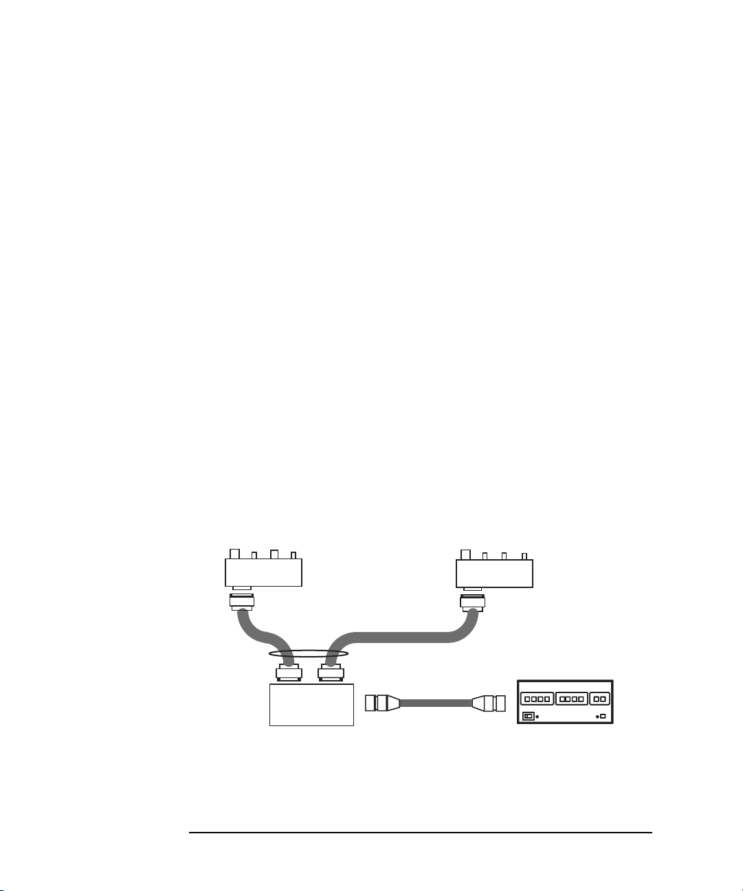
Hard ware Installation
Connecting Switch Controller
1. Install the switch controller and connect the GPIB cable. See “Installing
Instruments” and “Connecting Interface Cables” on page 2-7.
2. Fix the switch control distributor to the appropriate place.
3. Connect the viking cable between the switch controller and the switch
distributor.
4. Connect the D-sub 9 pin cable between the switch distributor Switch 1
connector and the gate pulse/dc switch unit.
5. Connect the D-sub 9 pin cable between the switch distributor Switch 2
connector and the drain pulse/dc switch unit.
Required accessories and equipment:
• Viking cable, 1 ea.
• D-sub 9 pin cable, 2 ea.
• Switch Controller, 1 ea.
• Switch Control Distributor, 1 ea.
• Gate Pulse/dc Switch Unit with divider, 1 ea.
• Drain Pulse/dc Switch Unit with bias-T, 1 ea.
Figure 2-6 Switch Controller, Switch Control Distributor, and Pulse/dc Switch Units
2-10 Keysight B1542A User’s Guide, Edition 10
Page 29

Making Measurement Path for Gate
Scope
DC source monitor
Triaxial cable
Pulse generator
to SMU Force
for gate voltage
at DC test
Gate pulse/dc switch unit
SMA cable, 0.3 m
BNC cable
SMA cable, 1.5 m
to input channel
for gate (*2)
Gate Pulse Monitor
SMU
to output channel for gate pulse (*1)
(*1) Use BNC(m)-SMA(f) adapter
for pulse generator.
(*2) Use BNC(m)-SMA(f) adapter
precision type for oscilloscope.
to TRIGGER OUT
to AUX Trig In
Gate Pulse Input
Connect the following accessories as shown in Figur e 2-7. And fi x the gate pulse/dc
switch unit to the appropriate place. Use a torque wrench and an open-end wrench to
fasten the SMA connectors.
Required accessories:
• BNC(m)-SMA(f) adapter, 1 ea., for pulse generator
• BNC(m)-SMA(f) adapter, precision type, 1 ea., for oscilloscope
• BNC cable, 1 ea.
• SMA cable, 0.3 m, 1 ea.
• SMA cable, 1.5 m, 1 ea.
• Triaxial cable, 1 ea.
Figure 2-7 Measurement Path for Gate
Installation
Hard ware Installation
Keysight B1542A User’s Guide, Edition 10 2-11
Page 30

Installation
Scope
DC source monitor
Triaxial cables
to SMU Force
for drain voltage
at DC test
to SMU
Force
for drain
DC bias
Drain pulse/dc switch unit
SMA cable, 0.3 m
Drain Current Monitor
SMU
to input channel
for drain
BNC(m)-SMA(f)
adapter precision type
Drain Bias Input
BNC(m)-Triax(f)
adapter (floating guard)
Hard ware Installation
Making Measurement Path for Drain
Connect the following accessories as shown in Figure 2-8. And fix the drain
pulse/dc switch unit to the appropriate place. Use a torque wrench and an open-end
wrench to fasten the SMA connectors.
Required accessories:
• BNC(m)-SMA(f) adapter, precision type, 1 ea., for oscilloscope
• SMA cable, 0.3 m, 1 ea.
• BNC(m)-Triax(f) adapter, floating guard, 1 ea.
• Triaxial cable, 2 ea.
Figure 2-8 Mea surement Path for Drain
2-12 Keysight B1542A User’s Guide, Edition 10
Page 31

Installation
to Drain
to Gate
SMA(m)-(m)
Terminator
SMA(f)-(m)-(f)
to Bias-T (RF+DC) or
to Drain pulse/dc switch unit (DUT)
to Divider or
to Gate pulse/dc switch unit (DUT)
DUT cable, 1.5 m
DUT cable, 1.5 m
1
2
Hard ware Installation
Connecting RF Probes
Only for the RF probe users. Connect the following accessories as shown in Figure
2-9. Use a torque wrench and an open-end wrench to fasten the SMA connectors.
Required accessories:
• DUT cable, 1.5 m, 2 ea.
• SMA(f)-(m)-(f) adapter, 1 ea.
•50 Terminator, 1 ea.
• SMA(m)-(m) adapter, 1 ea., used to connect the path to the RF probe for gate
Procedure:
1. Connect a DUT cable between a RF probe and the bias-T’ s RF+DC connector or
the Drain pulse/dc switch unit’s DUT connector of the pulsed IV test system.
And set the RF probe to the appropriate place.
2. Connect the SMA adapters, terminator, and a DUT cable between a RF probe
and the divider or the Gate pulse/dc switch unit’s DUT connector of the pulsed
IV test system. And set the RF probe to the appropriate place.
Figure 2-9 RF Probe Connections
Keysight B1542A User’s Guide, Edition 10 2-13
Page 32
Installation
Terminator
Well
Gate
Source
Drain
1
2
3
4
5
Gate DC probe
Source DC probe
Signal
Signal
Gnd
Gnd
SMA(f)-(m)-(f)
7
6
to Bias-T (RF+DC) or
to Drain pulse/dc switch unit (DUT)
to Divider or
to Gate pulse/dc switch unit (DUT)
DUT cable, 1.5 m
DUT cable, 1.5 m
Drain DC probe
Well DC probe
Hard ware Installation
Connecting DC Probes
Only for the DC probe users. Connect the following accessories as shown in Figure
2-10. Use a torque wrench and an open-end wrench to fasten the SMA connectors.
Required accessories:
• DUT cable, 1.5 m, 2 ea.
• SMA(f)-(m)-(f) adapter, 1 ea.
•50 Terminator, 1 ea.
• SMA(m)-SSMC cable, 1 ea. (part of the pulsed IV DC probe cable set)
• SMA(f)-SSMC cable, 1 ea. (part of the pulsed IV DC probe cable set)
• SSMC short-open cable, 3 ea. (parts of the pulsed IV DC probe cable set)
50 mm or 75 mm cable length. Use appropriate one. For the external view and
the internal connection, see Figure 2-11.
Figure 2-10 DC Probe Connections
2-14 Keysight B1542A User’s Guide, Edition 10
Page 33

Installation
50 mm or 75 mm
Black
SSMC(plug)
SSMC(plug)
Yellow
Signal line and shield are shorted.
no signal pin
Hard ware Installation
Procedure:
1. Connect the SMA(m)-SSMC cable to the Gate DC probe.
2. Connect a SSMC short-open cable between the Gate DC probe and the W ell DC
probe, and set the DC probe to the appropriate place. Then, the black sleeve plug
must be the Gate side. This electrically connects the Well probe needle, Well
probe shield, and Gate probe shield together.
3. Connect the SMA(f)-SSMC cable to the Drain DC probe, and set the DC probe
to the appropriate place.
4. Connect a SSMC short-open cable between the Drain DC probe and the Source
DC probe, and set the DC probe to the appropriate place. Then, the black sleeve
plug must be the Drain side. This electrically connects the Source probe needle,
Source probe shield, and Drain probe shield together.
5. Connect a SSMC short-open cable between the Well DC probe and the Source
DC probe, and set the DC probe to the appropriate place. Then, the black sleeve
plug must be the Source side. This electrically connects the Well probe needle,
Well probe shield, and Source probe shield together.
6. Connect a DUT cable between the Drain DC probe’s SMA(f) connector and the
bias-T’s RF+DC connector or the Drain pulse/dc switch unit’s DUT connector
of the pulsed IV test system.
7. Connect the SMA(f)-(m)-(f) adapter, terminator, and a DUT cable between the
Gate DC probe’s SMA(m) connector an d the divi der or the Gat e pul se/dc swi tch
unit’s DUT connector of the pulsed IV test system.
Figure 2-11 SSMC Short-Open Cable
Keysight B1542A User’s Guide, Edition 10 2-15
Page 34

Installation
Software Installation
Software Installation
This section describes the instructions to install the pulsed IV system software.
• “System Requirements”
• “Installing Software”
• “Installing Cable Compensation Data”
• “After Software Installation”
• “Updating Software”
• “Removing Pulsed IV Software”
To install the pulsed IV system software, perform the instructions described in
“Installing Software”, “Installing Cable Compensation Data”, and “After Software
Installation” in this order.
To update the pulsed IV system software, perform the instruction described in
“Updating Software”.
NOTE This section uses the following conventions.
<system drive>: Drive the pulsed IV system software is installed
<program folder>: Following folder
For Windows 7 64 bit version, <system drive>:\Program Files (x86)
For B1500A, Windows 7 32 bit version, and Windows XP,
<system drive>:\Program Files
<data folder>: Following folder
For Windows 7, <system drive>:\Program Data
For Windows XP, <system dri ve>:\Documents and Settings\All Users\Application
Data
2-16 Keysight B1542A User’s Guide, Edition 10
Page 35

Installation
Software Installation
System Requirements
The pulsed IV system software is allowed to be installed in the one of the following
system controller.
• Keysight B1500A installed with EasyEXPERT software
• Windows PC installed with Desktop EasyEXPERT software
If the B1500A is used as the DC s ource monit or , the revisi on number of Desktop
EasyEXPERT must be the same as the EasyEXPERT installed in the B1500A.
NOTE To install the pulsed IV system software, you must log on to Windows as an
administrator.
Installing Software
Install the pulsed IV system software as shown below.
1. Exit EasyEXPERT software or Desktop EasyEXPERT software. If the Start
EasyEXPERT window is opened, close it.
2. Insert the Pulsed IV package software CD-ROM into the disk drive.
3. Execute the setup.exe in the CD-ROM.
4. Follow the instructions of the setup wizard. And wait until the program
installation is completed.
5. After the installation, remove the CD-ROM from the disk drive.
Installing Cable Compensation Data
Install the drain cable compensation data as shown below.
1. If the Start EasyEXPERT window is opened, close it first.
2. Insert the Drain cable compensation data CD-ROM into the disk drive.
3. Execute the following file in the CD-ROM.
\DrainSetup\drain_setup.msi
4. Follow the instructions of the setup wizard. And wait until the data installation is
completed.
5. After the installation, remove the CD-ROM from the disk drive.
Keysight B1542A User’s Guide, Edition 10 2-17
Page 36

Installation
Software Installation
After Software Installation
1. Launch EasyEXPERT or Desktop EasyEXPERT. And click the Start
EasyEXPERT button.
2. Open your workspace or create a new workspace.
3. Display the Application Test tab screen.
4. Import the pulsed IV test definitions listed below from the following folder.
<program folder>\Agilent\PLSDIV\TestDefinitions\Import1st
• PLSDIV IdVd
• PLSDIV IdVd [2]
• PLSDIV IdVg
• PLSDIV IdVg [2]
• PLSDIV DC IdVd
• PLSDIV DC IdVg
• PLSDIV Capt Wave
• PLSDIV Setup
• PLSDIV Reset
• PLSDIV IV SMU
5. Import the pulsed IV test definitions listed below from the following folder.
<program folder>\Agilent\PLSDIV\TestDefinitions\Import2nd
• PLSDIV DC IdVd SMU
• PLSDIV DC IdVg SMU
6. Open the PLSDIV Setup test definition and perform the system setup as
described in Chapter 3, “Performing System Setup and Compensation.”
2-18 Keysight B1542A User’s Guide, Edition 10
Page 37

Installation
Software Installation
Updating Software
Perform the following procedure to update the pulsed IV system software.
1. Launch EasyEXPERT or Desktop EasyEXPERT. And click the Start
EasyEXPERT button.
2. Open your workspace.
3. Display the Application Test tab screen.
4. Remove checks from categories except for the Pulsed IV in the Category list.
5. Right-click a pulsed IV test definition in the Library list and click Delete
Definition of This Test to open the confirmation dialog box. And click OK to
delete the test definition from the present workspace.
Repeat this to delete all of the pulsed IV test definitions.
6. Remove the pulsed I V system soft ware now installed. See “Removing Pulsed IV
Software” on page 2-19.
7. Install the latest revision of the pulsed IV system software. See “Installing
Software” on page 2-17.
8. Install the drain cable compensation data. See “Installing Cable Compensation
Data” on page 2-17.
9. Import the pulsed IV test definitions. See “After Software Installation” on page
2-18.
Removing Pulsed IV Software
Perform the following procedure to remove the pulsed IV system software.
1. Exit EasyEXPERT software or Desktop EasyEXPERT software. If the Start
EasyEXPERT window is opened, close it.
2. Open the Control Panel.
3. Uninstall the pulsed IV system software.
4. Open the Explorer.
5. Delete the <program folder>\Agilent\PLSDIV folder.
6. Delete the <data folder>\Agilent\PLSDIV folder.
Keysight B1542A User’s Guide, Edition 10 2-19
Page 38
Installation
B1500A
Oscilloscope
Switch Controller
Switch Unit, 2 ea.
Pulse Generator
Blank Panel, 1 EIA
Blank Panel, 1 EIA
Rack-mounting Instruments
Rack-mounti n g Instrument s
Image of rack mount is shown in Figure 2-12. This figure shows the rack-mount
position of the instruments. For rack mounting the instruments, see manual of
instrument rack (Keysight E7590A: 1.3 m, E3661B: 1.6 m, E3662B: 2.0 m) and
rack-mount kit. For the required parts for rack-mounting oscilloscope, pulse
generator, and switch controller, see manual of each instrument.
Figure 2-12 Image of Rack Mount
See “Rack-mounting Pulse/dc Switch Units” on page 2-21 for rack-mounting the
switch units. The required parts for rack -mounting the switch units and t he B1500A
are listed in Table 2-1.
Table 2-1 Required Parts for Rack-mounting B1500A and Switch Units
Keysight Model No.
or Part No.
2-20 Keysight B1542A User’s Guide, Edition 10
Quantity Description
1 Rack-mount kit for pulse/dc switch units,
furnished with the B1542A
5063-9218 1 Rack-mount flange kit for B1500A, 7 EIA
E3663AC 1 Support rail kit, for B1500A
Page 39

Installation
Rack-mounting Instruments
Rack-mounting Pulse/dc Switch Units
Rack-mount pulse/dc switch units as shown below. The required parts are furnished
with the B1542A. See Figure 2-14.
Required parts:
Reference
Designator
A B1542-00201 1 Panel
B B1542-01211 1 Rail kit
C B1542-01212 1 Rail kit
- 0515-0372 12 Screw
Procedure:
1. Assemble the rail kits B and C as shown in Figure 2-13.
2. Secure the rail assemblies B and C to the proper position of the system rack by
using the typical rack-mounting method of the support rail kit.
3. Assemble the pulse/dc switch unit panel by mounting the following units on the
panel A. Use screws listed above to fix the units.
Reference
Designator
Keysight Part No. Quantity Description
Keysight Part No. Description
D B1542-60001 Switch control distributor
E B1542 -60002 Drain pulse/dc switch unit
F B1542-600 03 Gate pulse/dc switch unit
4. Align the pulse/dc switch unit panel (A with D, E, and F) with the rail
assemblies secured to the system rack in the step 2, gently slide the panel on the
rails until it stops, and secure the panel to the system rack by using the typical
rack-mounting method of the rack-mount flange kit.
Keysight B1542A User’s Guide, Edition 10 2-21
Page 40

Installation
B1542-01212
B1542-01211
Screw
Screw hole
Screw hole
Screw hole, not used
Screw hole, not used
C
A
B
E
D
F
4
2
2
3
Rack-mounting Instruments
Figure 2-13 Assembling Rail Kit
Figure 2-14 Rack-mounting Pulse/dc Switch Units
2-22 Keysight B1542A User’s Guide, Edition 10
Page 41

3 Performing System Setup and
Compensation
Page 42

Performing System Setup and Compensation
This chapter describes how to perform system setup and compensation of the pulsed
IV test system and consists of the following sections. The system setup can be
performed by using the pulsed IV set up (PLSDIV Setup) test definition on the
EasyEXPERT application test environment.
• “Pulsed IV System Setup”
• “Starting System Setup”
• “System Configuration”
• “Executing Action”
NOTE Before Starting System Setup
The pulsed IV test system must be installed correctly. See Chapter 2, “Installation.”
Then do not forget to install the compensation data files.
NOTE Drain Cable Replacement
It is inadequate to replace only the defective part when you find any defect in the
drain measurement path. The compensation data of the measurement path must be
also updated after the replacement.
Order the drain cable set and replace it. After that, perform the compensation data
installation. For the cable connection and the compensation data installation, see
Chapter 2, “Installation.”
3-2 Keysight B1542A User’s Guide, Edition 10
Page 43

Performing System Setup and Compensation
Pulsed IV System Setup
Pulsed IV System Setup
The pulsed IV system setup items are listed below. The system setup must be
performed and successfully completed before using the pulsed IV test system.
Accessories needed to perform the system setup are listed in Table 3-1. Prepare the
accessories additionally to the system accessories and the system components.
• System Configuration
This action is necessary to specify the interface address and the source or
measurement channels of PGU (pulse generator), DSO (digital sampling
oscilloscope), and SMU (source monitor unit) used for the pulsed IV
measurement. See “System Configuration” on page 3-10. For the setup
parameters, see Table 3-3.
• Compensation
This action is necessary to obtain and update the compensation factors of the
pulsed IV test system.
• Skew Measurement
This action performs the skew measurement which is one of the measurements
performed in the Compensation action. If the skew measurement error occurs
during the Compensation action is executed, you can perform only the skew
measurement again by this action.
• Drain Cable Replacement
This action is necessary to obtain and update the compensation factors of the
bias-T and the cable of the drain measurement path.
• Pgu Compensation
This action obtains the compensation factors of the pulse generator. This action
should be executed before you perform the pulsed IV measurements which set
the gate voltage automatic adjustment (VgAdjust) to off (Disable).
When you must perform the system setup is shown in Table 3-2.
To execute an action, see “Executing A ction” on pag e 3-12.
Keysight B1542A User’s Guide, Edition 10 3-3
Page 44

Performing System Setup and Compensation
Pulsed IV System Setup
Table 3-1 Required Accessories to Perform System Setup
Accessory Quantity
Triaxial cable 2
BNC cable 1
BNC(m)-Triax(f) adapter, floating guard 1
BNC(m)-(f)-(f) adapter 1
GNDU-chassis adapter 1
Table 3-2 Pulsed IV System Setup
When the action must be executed Action
after system installation System Configuration
after changing interface address of an instrument System Configuration
Compensation
after changing a channel assignment System Configuration
Compensation
after repair of oscilloscope Compensation
after calibration of oscilloscope Compensation
after replacing oscilloscope Compensation
after replacing bias-T Drain Cable Replacement
after replacing measurement cables to drain
terminal
before starting the pulsed IV measurements with
the VgAdjust=Disable condition
if the skew measurement error occurs Skew Measurement
3-4 Keysight B1542A User’s Guide, Edition 10
Drain Cable Replacement
Pgu Compensation
Page 45

Performing System Setup and Compensation
Pulsed IV System Setup
Table 3-3 System Configuration Setup Parameters
Field name Description
Controller Select B1500A Internal or External PC.
Instrumentations PGU, DSO, and SMU Specify the pulse generator (PGU), oscilloscope (DSO),
and DC source monitor (SMU) to be used.
For DSO/MSO S series oscilloscope, set
DSO=DSO9000A series.
Visa Name
a
VISA interface ID of the GPIB interface. It must be
GPIB0.
b
GPIB Address
PGU, DSO, and SMU Enter GPIB address of the pulse generator (PGU),
oscilloscope (DSO), and DC source monitor (SMU).
If Controller=B1500 Internal, SMU field is not active.
If DSO=DSO9000A series, DSO field is not active.
Option button Opens a dialog box. See “LAN Set up for DSO Cont ro l
Dialog Box” on page 3-10.
CH Assignment Gate PGU CH Enter DSO channel number for Gate pulse output.
Gate Monitor DSO CH Enter DSO channel number for Gate voltage monitor.
Drain Monitor DSO
Enter DSO channel number for Drain voltage monitor.
CH
Drain Bias SMU CH Enter SMU slo t number for Drain voltage output.
SMU for Compensation button Opens a dialog box. See “SMU CH for Compensation
Dialog Box” on page 3-11.
a. To know the Visa Name, use Keysight Connection Expert. See Figure 3-1 or Figure 3-2.
b. To know the GPIB address of the instruments, use Keysight Connectio n Expert on the system
controller. Or see the manual of each instrument to know how to set the GPIB address.
Keysight B1542A User’s Guide, Edition 10 3-5
Page 46

Performing System Setup and Compensation
Starting System Setup
Starting System Setup
Perform the following procedures. If you use the DSO/MSO 9000 series or S series
oscilloscope, also perform the procedure described in “If You Use DSO/MSO 9000
Series or S Series Oscilloscope” on page 3-7.
NOTE If you use an external computer as the system controller, skip the following
procedures and perform the procedures described in “If You Use External
Computer” on page 3-8.
1. Connect GPIB cable between the B1500A and the system instruments if it is still
not connected.
2. Connect BNC cable between the pulse generator TRIGGER OUT connector and
the oscilloscope AUX Trig In connector if it is still not connected.
3. Turn on the system instruments.
On the Keysight
Connection Expert
On the
EasyEXPERT
1. If the B1500A displays the Start EasyEXPERT window, close it first.
2. Launch Keysight Connection Expert (see Figure 3-1).
3. Check the GPIB configuration. The System Controller must be set to Yes.
4. Check the VISA interface ID. It must be GPIB0.
5. Close Keysight Connection Expert.
1. Launch EasyEXPER T.
2. Click th e Start EasyEXPERT button.
3. Open your workspace or create a new workspace.
4. Display the Application Test tab screen.
5. Open the PLSDIV Setup test definition.
6. Set the DcSwitch field to Yes. Do not set No.
7. Save the test setup to your preset group (My Favorite Setup).
3-6 Keysight B1542A User’s Guide, Edition 10
Page 47
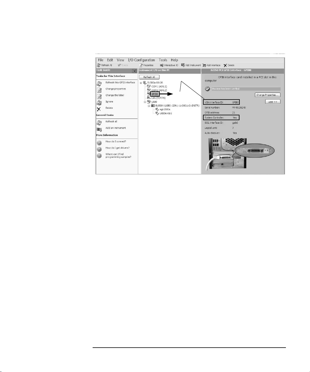
Figure 3-1 Keysight Connection Expert
GPIB0
System Controller
VISA interface ID
Performing System Setup and Compensation
Starting System Setup
If You Use DSO/MSO 9000 Series or S Series Oscilloscope
Perform the following procedure to know the IP address of the DSO/MSO 9000
series or S series oscilloscope and set it to Keysight Connection Expert. It must be
also set to the system setup configuration (see IP Address in Table 3-5). Before
performing this procedure, the oscilloscope and B1500A (or computer) must be
connected to the LAN of the same subnet mask.
1. On the oscilloscope front panel, check the IP address of the oscilloscope. See the
2. If the B1500A (or computer) displays the Start EasyEXPERT window, close it
3. Launch Keysight Connection Expert.
4. Highlight LAN(TCPIP0).
5. Add the oscilloscope to the LAN instruments. Then use the IP address checked
6. Close Keysight Connection Expert.
Keysight B1542A User’s Guide, Edition 10 3-7
oscilloscope manual for checking the IP address (web address).
first.
at the step 1. Also the Device name must be inst0.
Page 48

Performing System Setup and Compensation
Starting System Setup
If You Use External Computer
Perform the following procedures if you use an external computer as the system
controller. If you use the DSO/MSO 9000 series or S series oscilloscope, also
perform the procedure described in “If You Use DSO/MSO 9000 Series or S Series
Oscilloscope” on page 3-7.
NOTE If You Use B1500A as DC Source Monitor
Launch Keysight Connecti on Exp ert o n the B1 500A and set t he GPI B config uration
as follows.
• GPIB address: appropriate value, non 21 value
• System Controller: No
After that reboot the B1500A and leave the Start EasyEXPERT window on the
B1500A screen.
1. Connect GPIB cable between the system controller and the system instruments
if it is still not connected.
2. Connect BNC cable between the pulse generator TRIGGER OUT connector and
the oscilloscope AUX Trig In connector if it is still not connected.
On the Keysight
Connection Expert
On the Desktop
EasyEXPERT
3. Turn on the system instruments.
1. If the computer displays the Start EasyEXPERT window, close it first.
2. Launch Keysight Connection Expert (see Figure 3-2).
3. Check the VISA interface ID. It must be GPIB0.
4. Close Keysight Connection Expert.
1. Launch Desktop EasyEXPERT.
2. Open the Execution Mode dialog box and set the execution mode as shown in
Table 3-4. The dialog box can be opened by selecting the Option > Execution
Mode menu on the Start EasyEXPERT window.
3. Click th e Start EasyEXPERT button.
4. Open your workspace or create a new workspace.
5. Display the Application Test tab screen.
6. Open the PLSDIV Setup test definition.
7. Set the DcSwitch field to Yes. Do not set No.
3-8 Keysight B1542A User’s Guide, Edition 10
Page 49

Performing System Setup and Compensation
GPIB0
VISA interface ID
System Controller
GPIB address
hostname1
4156C (GPIB0::17::INSTR)
4156C (GPIB0::17::INSTR)
GPIB address of instrument
(ex. 4156C)
8. Save the test setup to your preset group (My Favorite Setup).
Table 3-4 Desktop EasyEXPERT Execution Mode
Mode Field name Setting value or description
a
Offline
Select this mode for using the 4155B, 4155C, 4156B, 4156C,
E5260A (or E5262A/E5263A) , or E5270B .
Model Select 4155B, 4155C, 4156B, or 4156C to be
used. Or select B1500A for using the E5260A
(or E5262A/E5263A) or E5270B.
Online Select this mode only for using the B1500A.
VISA interface ID VISA interface ID of the computer’s GPIB
interface. It must be GPIB0.
GPIB address Set the GPIB address of the B1500A.
a. Even though the execution mode is Offline, the pulsed IV system soft-
ware can control the DC source monitor.
Starting System Setup
Figure 3-2 Keysight Connection Expert
Keysight B1542A User’s Guide, Edition 10 3-9
Page 50

Performing System Setup and Compensation
System Configuration
System Configuration
The system configuration must be set after completing the system installation or
after changing a channel assignment or after changing the interface address of the
system components.
Procedure:
1. Open the PLSDIV Setup test setup from your preset group.
2. Set the Action field to System Configuration.
3. Click the Single button at the upper right corner on the EasyEXPERT screen or
the Desktop EasyEXPERT screen. The Configuration dialog box is opened.
4. Set and save the system configuration parameters by using the Configuration
dialog box. For the setup parameters, see Table 3-3.
LAN Setup for DSO Control Dialog Box
This dialog box is opened by clicking the Option button on the Configuration dialog
box, and is used to set the IP address of the DSO/MSO 9000 series or S series
oscilloscope. Set the IP address properly and click OK.
Table 3-5 LAN Setup for DSO Control Dialog Box
Field Name Description
IP Address Enter the IP address of the DSO/MSO 9000 series or S
series oscilloscope.
Device Name This field always displays inst0 which must be the
device name of the oscilloscope for the pulsed IV test
system.
3-10 Keysight B1542A User’s Guide, Edition 10
Page 51

SMU CH for Compensation Dialog Box
This dialog box is opened by clicking the SMU for Compensation button on the
Configuration dialog box, and is used to specify the SMU used for the
Compensation action.
In the default setting, the Compensation action will use the SMU specified by the
Drain Bias SMU CH field on the Configuration dialog box. For example, if 2 has
been set to this field, the Compensation action uses the SMU2 or the SMU installed
in the slot number 2.
However, if you specify a SMU on the SMU CH for Compensation dialog box, see
Table 3-6, the Compensation action will use the SMU you specify, not the Drain
Bias SMU CH channel.
Table 3-6 SMU CH for Compensation
Field Name Description
Force SMU (Slot No.) Channel number (slot number) of the SMU used for
the Kelvin connection Force.
Sense SMU (Slot No.) Enter the channel number (slot number) of the SMU
used for the Kelvin connection Sense.
Performing System Setup and Compensation
System Configuration
If you are using the DC source monitor other than the 4155B/C, you do not need to
specify the SMU. However, if you want to use the SMU other than the Drain Bias
SMU CH channel, set the same value to the both fields. The Compensation action
will use the specified SMU.
If you are using the 4155B/C, specify two SMUs because the 4155B/C does not
have the Sense terminal. The Compensation action will use the specified two SMUs
for making the Kelvin connection.
Keysight B1542A User’s Guide, Edition 10 3-11
Page 52

Performing System Setup and Compensation
Executing Action
Executing Action
Execute the action as shown below. Before starting the action, confirm that all
system components are connected to th e system controller and available on the same
GPIB bus and on the same LAN for the DSO/MSO 9000 series or S series
oscilloscope.
1. Open the PLSDIV Setup test setup from your preset group.
2. Set the DcSwitch field to Yes. Do not set No.
3. Click the Extended Setup button and set the SWAddress value.
SWAddress GPIB address of the switch controller. Integer, 1 to 32.
4. Select the action by using the Action field.
• System Configuration
See “System Configuration” on page 3-10.
• Compensation
See “Compensation Action” on page 3-13.
• Skew Measurement
• Drain Cable Replacement
• Pgu Compensation
See “Pgu Compensation Action” on page 3-13.
5. Click the Single button at the upper right corner of the EasyEXPERT screen or
the Desktop EasyEXPERT screen.
6. Follow the pop-up window and dialog box to complete the action.
You will get navigation for performing the system setup and completing the
action.
3-12 Keysight B1542A User’s Guide, Edition 10
Page 53

Performing System Setup and Compensation
Executing Action
Compensation Action
Before starting the Compensation action, connect triaxial cables as follows.
1. Connect a triaxial cable to the Force connector of the SMU specified by the
Drain Bias SMU CH field on t he Configurat ion dialog box or the S MU specified
by the Force SMU (Slot No.) field on the SMU CH for Compensation dialog box
if you set.
2. Connect a triaxial cable to the Sense connector of the SMU specified by the
Drain Bias SMU CH field on t he Configurat ion dialog box or the S MU specified
by the Sense SMU (Slot No.) field on the SMU CH for Compensation dialog box
if you set.
If you are using the 4155B/C, connect the cable to the Force connector of the
SMU specified by the Sense SMU (Slot No.) field on the SMU CH for
Compensation dialog box.
Pgu Compensation Action
Previously, the Compensation action must be completed successfully.
Before starting the Pgu Compensation action, click the Extended Setup button and
set the following parameters. They must be the values you are going to set when
performing the pulsed IV measurements actually.
PulseBase PGU output baseline voltage, -3.0 to 3.0 V
TransTime Pulse leading/trailing edge transition time, 2 ns to 500 ns
MeasTime Measurement timing at the pulse top, -1 to 1
For the setup parameters, see “Parameters” on page 5-34.
Keysight B1542A User’s Guide, Edition 10 3-13
Page 54

Performing System Setup and Compensation
Executing Action
3-14 Keysight B1542A User’s Guide, Edition 10
Page 55

4 Performing Measurement
Page 56

Performing Measurement
This chapter describes the measurement examples by using the pulsed IV test
system, and consists of the following sections.
• “Theory of Measurement”
• “Before Measurement”
• “Performing System Reset”
• “Pulse Waveform Measurement”
• “Pulsed Id-Vd Measurement”
• “Pulsed Id-Vg Measurement”
• “DC I-V Measurements”
NOTE Preparing Measurement Environment
Complete the installation described in Chapter 2, “Installation.”
Complete the system setup and the compensation described in Chapter 3,
“Performing System Setup and Compensation.”
Turn on the instruments. And turn on the system controller if it is used.
Launch EasyEXPERT or Desktop EasyEXPERT.
4-2 Keysight B1542A User’s Guide, Edition 10
Page 57

Theory of Measurement
S
D
G
Sub
+
DC+RF
RF
DC
Divider
Oscilloscope
drain voltage
monitor channel
Gate pulse voltage
Drain voltage
Oscilloscope
gate voltage
monitor channel
Vd
v
Vg
Terminator
PGU
SMU
Bias-T
v
A
Figure 4-1 shows the pulsed IV measurement circuit diagram.
SMU (source monitor unit) applies DC voltage to the drain terminal through bias-T
(bias network). And PGU (pulse generator) applies pulse voltage to the gate
terminal through divider. Then the oscilloscope monitors the gate pulse through the
divider. Also the oscilloscope monitors the drain pulse through the bias-T by using
the another monitor channel.
The 50 terminator must be connected as shown in Figure 4-1 to keep the
impedance matching of the instrument’s input/output terminals and to avoid the
reflection at the gate terminal.
Figure 4-1 P ulsed IV Measurement Circuit Diagram
Performing Measurement
Theory of Measurement
Simplified measurement circuit is shown in Figure 4-2.
Vpgu-out is the PGU output voltage (pulse top value). And VdSet is the SMU
output voltage. By applying VdSet and Vpgu-out to the MOSFET, the
oscilloscope’s drain voltage monitor channel will capture the voltage drop caused by
the shunt resistor Z (impedance of the drain voltage measurement path). And the
drain current Id can be given by the following formula. Where, VdInt is the peak
value of the negative pulse.
Id = (VdSet - VdInt) / Z
Keysight B1542A User’s Guide, Edition 10 4-3
Page 58

Performing Measurement
D
S
G
Shunt resistor, Z
VdSet
Id
VgMon
Vpgu-out
VdInt = VdSet Z Id
PGU
SMU
Sub
Theory of Measurement
The test system repeats this drain current measurement for all of the specified sweep
voltage and gets the data to plot on the data display graph.
Figure 4-2 Simplified Measurement Circuit
VgMon, VdInt, and Id values will be the value obtained at the specific timing of the
pulse top. It is the data extraction timing shown in Figure 5-9.
Terminal Voltage and Source Output Value
In Figure 4-2, VgMon and VdInt are the device terminal voltage. Vpgu-out and
VdSet are the source output values. Moreover the values are not same becaus e of the
several elements in the measurement path, shunt resistor , residual resistor , and so on.
Therefore, it is required to select which value should be the target voltage before
performing the measurement. To select it, use the drain voltage automatic
adjustment function and the gate voltage automatic adjustment function in the
pulsed IV test definitions.
If the drain voltage automatic adjustment function is ON, VdInt will be close to the
target voltage Vd. And if the function is OFF, VdSet will be close to Vd.
If the gate voltage automatic adjustment function is ON, VgMon will be close to the
target voltage Vg. And if the function is OFF, Vpgu-out will be close to Vg.
The target voltage Vd is calculated from the Test Parameters VdStart, VdStop, and
VdStep in the pulsed IV test definition. And Vg is calculated from VgStart, VgStop,
and VgStep.
4-4 Keysight B1542A User’s Guide, Edition 10
Page 59

Performing Measurement
After adjustmentBefore adjustment
Drain monitor pulse
Device Delay
Gate monitor pulse
Drain monitor pulse
Gate monitor pulse
Before Measurement
Before Measurement
Confirm or perform the followings before starting measurement.
1. Performing system reset
Perform system reset. See “Performing System Reset” on page 4-6.
2. Deciding device delay time
This is needed to set the DeviceDelay value of the Device Parameters on the
pulsed IV test setup screen.
Connect the device under test (MOS FET) to the pulsed IV test system as sh own
in “RF Probes” on page 2-4, and measure the delay time between the gate
monitor pulse and the drain monitor pulse by using the oscilloscope. Then
decide the device delay time shown in Figure 4-3.
3. DcSwitch value on Extended Setup dialog box of pulse d IV test setup
Set Yes to use the pulse/dc switch. Do not set No.
4. SWAddress value on Extended Setup dialog box of pulsed IV test setup
Set GPIB address of the switch controller.
Figure 4-3 Device Delay Time
Keysight B1542A User’s Guide, Edition 10 4-5
Page 60
Performing Measurement
Performing System Reset
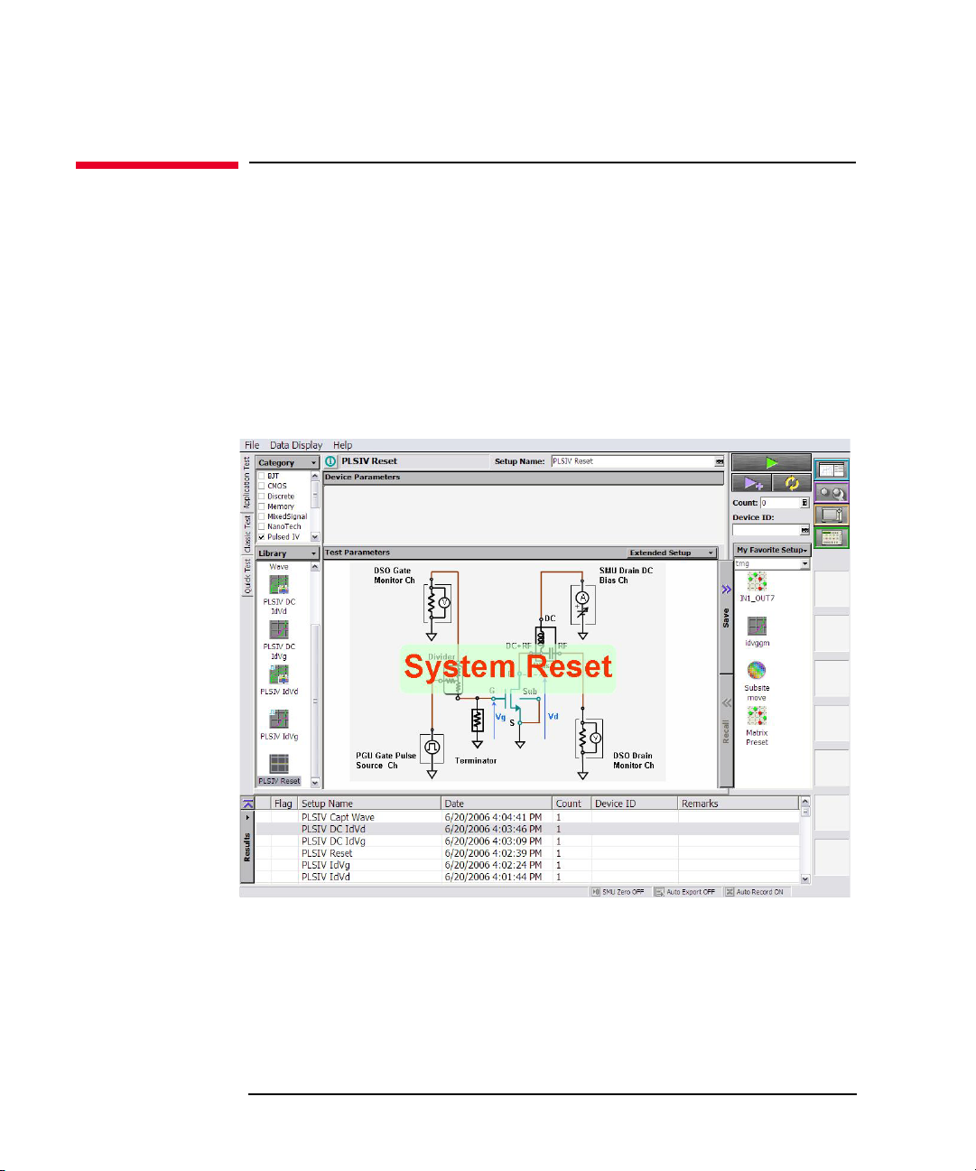
Performing System Reset
This test definition resets the pulsed IV test system. Execute this definition when the
test system is in any abnormal condition.
1. Open the PLSDIV Reset test definition on the EasyEXPERT application test
environment.
2. Click the Single button at the upper right corner of the EasyEXPERT screen.
The system reset is performed.
Figure 4-4 PLSDIV Reset Test Definition
4-6 Keysight B1542A User’s Guide, Edition 10
Page 61

Pulse Waveform Measurement
Pulse waveform measurement can be performed as follows.
Figure 4-5 PLSDIV Capt Wave Test Definition
Performing Measurement
Pulse Waveform Measurement
1. Open the PLSDIV Capt Wave test definition on the EasyEXPERT applicati on
test environment.
2. Set the measurement condition to the Device Parameters, Test Parameters, and
Extended Test Parameters. For the description of the entry fields, see “PLSDIV
Capt Wave” on page 5-4.
3. Connect the device under test (MOSFET) as shown i n “RF Pr obes ” on page 2-4.
4. Click the Single button at the upper right corner of the EasyEXPERT screen.
Pulse waveform measurement is started.
Figure 4-6 is the measurement result example when DrainMonMode=Voltage,
and Figure 4-7 is the example when DrainMonMode=Current.
Keysight B1542A User’s Guide, Edition 10 4-7
Page 62

Performing Measurement
Pulse Waveform Measurement
Figure 4-6 Voltage Pulse Measurement Example
Figure 4-7 Current Pulse Measurement Example
4-8 Keysight B1542A User’s Guide, Edition 10
Page 63

Pulsed Id-Vd Measurement
Pulsed Id-Vd measurement can be performed as follows.
Figure 4-8 PLSDIV IdVd Test Definition
Performing Measurement
Pulsed Id-Vd Measurement
1. Open the PLSDIV IdVd or PLSDIV IdVd [2] test definition on the
EasyEXPERT application test environment.
2. Set the measurement condition to the Device Parameters, Test Parameters, and
Extended Test Parameters. For the description of the entry fields, see “PLSDIV
IdVd, PLSDIV IdVd [2]” on page 5-19.
3. Connect the device under test (MOSFET) as shown i n “RF Pr obes ” on page 2-4.
4. Click the Single button at the upper right corner of the EasyEXPERT screen.
Pulsed Id-Vd measurement is started.
Figure 4-9 shows the pulsed Id-Vd measurement result example.
Keysight B1542A User’s Guide, Edition 10 4-9
Page 64

Performing Measurement
Pulsed Id-Vd Measurement
Figure 4-9 Pulsed Id-Vd Measurement Examp le
4-10 Keysight B1542A User’s Guide, Edition 10
Page 65

Pulsed Id-Vg Measurement
Pulsed Id-Vg measurement can be performed as follows.
Figure 4-10 PLSDIV IdVg Test Definition
Performing Measurement
Pulsed Id-Vg Measurement
1. Open the PLSDIV IdVg or PLSDIV IdVg [2] test definition on the
EasyEXPERT application test environment.
2. Set the measurement condition to the Device Parameters, Test Parameters, and
Extended Test Parameters. For the description of the entry fields, see “PLSDIV
IdVg, PLSDIV IdVg [2]” on page 5-23.
3. Connect the device under test (MOSFET) as shown i n “RF Pr obes ” on page 2-4.
4. Click the Single button at the upper right corner of the EasyEXPERT screen.
Pulsed Id-Vg measurement is started.
Figure 4-11 shows the pulsed Id-Vg measurement result example.
Keysight B1542A User’s Guide, Edition 10 4-11
Page 66

Performing Measurement
Pulsed Id-Vg Measurement
Figure 4-11 Pulsed Id-Vg Measurement Example
4-12 Keysight B1542A User’s Guide, Edition 10
Page 67
DC I-V Measurements
The PLSDIV system software also provides the test definitions for the DC I-V
measurements. The test definitions use SMU and do not use oscilloscope and pulse
generator. However, you can perform the measurement as shown in the previous
sections.
Table 4-1 li sts the DC I-V test definitions and the instruments supported by them.
Table 4-1 DC I-V Test Definitions
Test Definition Suppo rted Instruments
PLSDIV DC IdVd B1500A
Performing Measurement
DC I-V Measurements
PLSDIV DC IdVg
PLSDIV DC IdVd SMU E5260A (or E5262A/E5263A)
PLSDIV DC IdVg SMU
PLSDIV IV SMU
4155B/C and 4156B/C
E5270B
Keysight B1542A User’s Guide, Edition 10 4-13
Page 68

Performing Measurement
DC I-V Measurements
4-14 Keysight B1542A User’s Guide, Edition 10
Page 69

5 PLSDIV Test Definitions
Page 70

PLSDIV Test Definitions
This chapter describes the pulsed IV application test library (PLSDIV test
definitions) that can be opened and executed in the EasyEXPERT application test
environment. The library contains the test definitions shown in Table 5-1.
Each section in this chapter contains detailed descriptions of the test definition. Each
entry:
1. Gives one definition
2. Shows the measurement result example
3. Describes the setup paramet ers
4. Describes the test output parameters
5. Explains any additional information
The test definitions are shown in the alphabetical order.
NOTE This chapter uses the following conventions.
<system drive>: Drive the pulsed IV system software is installed
<program folder>: Following folder
For Windows 7 64 bit version, <system drive>:\Program Files (x86)
For B1500A, Windows 7 32 bit version, and Windows XP,
<system drive>:\Program Files
NOTE The PLSDIV test definitions are stored in the following folder.
<program folder>\Agilent\PLSDIV\TestDefinitions
To use the PLSDIV test definitions, import the definitions to your workspace. The
test definitions can be imported by the following procedure.
1. Display the Application Test tab screen.
2. Click the Library button, and select Import Test Definition... to open the Test
Definition Import dialog box.
3. Import the definitions by using the Test Definition Import dialog box.
Note that the PLSDIV test definitions need the pulsed IV .exe library (Plsdiv
commands, PLSDIV TIS) described in Chapter 6, “PLSDIV TIS Commands.”
5-2 Keysight B1542A User’s Guide, Edition 10
Page 71

PLSDIV Test Definitions
Table 5-1 Summary of PLSDIV Test Definitions
Test Definition Description
PLSDIV Setup This test definition must be executed after installing the pulsed IV test
system, changing channel assignment or GPIB address, or replacing
oscilloscope, cable, or bias-T.
PLSDIV Reset Initializes the pulsed IV test system.
PLSDIV Capt Wave Controls SMU to apply the drain voltage, controls PGU to apply the gate
voltage pulse, controls the oscilloscope to monitor the gate voltage pulse
waveform and the drain voltage pulse waveform, calculates the drain current
pulse waveform if the drain monitor mode is current, and displays the gate
voltage pulse waveform and the drain voltage or current pulse waveform.
PLSDIV IdVd,
PLSDIV IdVd [2]
PLSDIV IdVg,
PLSDIV IdVg [2]
PLSDIV DC IdVd,
PLSDIV DC IdVd SMU
PLSDIV DC IdVg,
PLSDIV DC IdVg SMU
PLSDIV IV SMU For the DC IV sweep measurement. Controls SMUs to apply the primary and
Controls SMU (source monitor unit) to apply the drain voltage, controls PGU
(pulse generator) to apply the gate voltage pulse, controls the oscilloscope to
monitor the gate voltage and the drain voltage, calculates the drain current,
and displays the Id-Vd characteristics.
Controls SMU to apply the drain voltage, controls PGU to apply the gate
voltage pulse, controls the oscilloscope to monitor the gate voltage and the
drain voltage, calculates the drain current, and displays the Id-Vg
characteristics.
For the DC Id-Vd measurement. Controls SMUs to apply the drain voltage
and the gate voltage, measures the drain current, and displays the Id-Vd
characteristics.
For the DC Id-Vg measurement. Controls SMUs to apply the drain voltage
and the gate voltage and measure the drain current, and displays the Id-Vg
characteristics.
secondary sweep voltage, measures current, and displays the I-V
characteristics.
For the DC I-V test definitions and the supported instruments, see Figure 4-1 on
page 4-13.
Keysight B1542A User’s Guide, Edition 10 5-3
Page 72

PLSDIV Test Definitions
Drain monitor pulse
Gate monitor pulse
PLSDIV Capt Wave
PLSDIV Capt Wave
This test definition controls SMU (source monitor unit) to apply the drain voltage,
controls PGU (pulse generator) to apply the gate voltage pulse, controls the
oscilloscope to monitor the gate voltage pulse waveform and the drain voltage pulse
waveform, calculates the drain current pulse waveform if the drain monitor mode is
current, and displays the gate voltage pulse waveform and the drain voltage or
current pulse waveform.
Figure 5-1 Pulse Waveform Measurement Re sult Example
Device Parameters The following parameters are available to set the test condition.
Polarity Polarity of source output. Nch (applies the specified value) or
Pch (applies the negative specified value). See “Parameters” on
page 5-34.
Lg Gate length, in m. 1 nm, 4 digits or 1 nm resolution.
Wg Gate width, in m. 1 nm, 4 digits or 1 nm resolution.
Temp Temperature, in degree. 4 digits or 0.001 degree resolution.
IdMax Maximum drain current measurement range, in A. 0 to 80 mA,
4 digits or 1 A resolution.
DeviceDelay Delay time caused by device under test, in s. -1 s to 1 s,
4 digits or 100 ps resolution. See “Parameters” on page 5-34.
5-4 Keysight B1542A User’s Guide, Edition 10
Page 73

PLSDIV Test Definitions
Test Parameters The following parameters are available to set the source output.
PulseWidth Pulse width of PGU output pulse. 10 ns to 1 s, 4 digits or 1 ns
resolution. See “Parameters” on page 5-34.
Vg Voltag e applied to the g ate terminal. PGU output. -4.5 V to
4.5 V, 4 digits or 10 mV resolution.
PulseBase PGU output baseline voltage. -3.0 to 3.0 V, 4 digits or 10 mV
resolution. See “Parameters” on page 5-34. Pulse amplitude
must be > 55 mV and < 4.5 V. To use the gate voltage automatic
adjustment function, set the pulse amplitude to < 4.0 V.
Vd Voltage applied to the drain terminal. SMU output. -10 V to
10 V, 5 digits or 1 mV resolution.
PLSDIV Capt Wave
Extended Test
Parameters
The following parameters are available to set the test condition. For more details,
see “Parameters” on page 5-34.
TransTime Pulse leading/trailing edge transition time, in s. 2 ns to 500 ns, 3
digits or 1 ns resolution.
For the 81101A, minimum value is 5 ns.
For the 81150A, minimum value is 2.5 ns when the following
conditions are satisfied, or 7.5 ns.
• Pulse amplitude is 2.5 V or less.
• Both pulse base and top are within 2.5 V.
MeasTime Measurement timing at the pulse top. 0 to 1, 3 digits or 0.01
resolution.
SmplNum Oscilloscope sampling number. 16 to 262144, 6 digits or 1 step.
SmthNum Oscilloscope smoothing number. 3 to 4001, 4 digits or 1 step.
SmthStat Status of the oscilloscope smoothing. Enable or Disable.
AvgNum Oscilloscope averaging number. 1 to 4095, 4 digits or 1 step.
VdAdjust Status of the drain voltage automatic adjustment. Enable or
Disable.
VgAdjust Status of the gate voltage automatic adjustment. Enable or
Disable.
ConnectChk Status of the connection check at initialization. Enable or
Disable.
Keysight B1542A User’s Guide, Edition 10 5-5
Page 74

PLSDIV Test Definitions
PLSDIV Capt Wave
GateZero Status of the gate monitor channel zero measurement at
initialization. Enable or Disable.
RangingMode Measurement ranging mode. Auto or Fixed.
DcSwitch Pulse/dc switch units. Yes (exists, pulsed IV measurement
connection will be automatically made) or No (none).
SWAddress GPIB address of the switch controller. Integer, 1 to 32.
DrainMonMode Drain monitor mode. Current or Voltage.
Test Output The following output parameters are displayed after the test.
Time Oscilloscope time data, in s.
GateMon Oscilloscope gate voltage waveform data, in V.
DrainMon Oscilloscope drain current waveform, in A, if
DrainMonMode=Current.
Drain voltage waveform data, in V, if DrainMonMode=Voltage.
The drain voltage waveform data will be the data after compensation.
The drain current waveform data will be the data given by converting the drain
voltage waveform data.
5-6 Keysight B1542A User’s Guide, Edition 10
Page 75

PLSDIV Test Definitions
PLSDIV DC IdVd
This test definition controls SMUs to apply the drain voltage and the gate voltage,
measures the drain current, and displays the Id-Vd characteristics.
Device Parameters The following parameters are available to set the test condition.
Polarity Polarity of source output. Nch (applies the specified value) or
Pch (applies the negative specified value).
Lg Gate length, in m. 1 nm, 4 digits or 1 nm resolution.
Wg Gate width, in m. 1 nm, 4 digits or 1 nm resolution.
Temp Temperature, in degree. 4 digits or 0.001 degree resolution.
IdMax Maximum drain current measurement range, in A. 0 to 80 mA,
4 digits or 1 A resolution.
Test Parameters The following parameters are available to set the source output.
CableR Residual resistance of the gate measurement path f rom SMU to
terminator. 0 , 4 digits or 1 m resolution.
PLSDIV DC IdVd
TermR Resistance of terminator. 1 m, 4 digits or 1 m resolution.
TermR=No applies 1E+30 .
Gate SMU connected to the gate terminal.
VgStart Secondary sweep start voltage for the gate terminal. -10 to 10
V, 4 digits or 10 mV resolution.
VgStop Secondary sweep stop voltage for the gate terminal. -10 to 10
V, 4 digits or 10 mV resolution.
VgStep Secondary sweep step voltage for the gate terminal.-10 to 10 V,
5 digits or 1 mV resolution.
Drain SMU connected to the drain terminal.
VdStart Primary sweep start voltage for the d rain terminal. -10 to 10 V,
4 digits or 10 mV resolution.
VdStop Primary sweep stop voltage for the drain terminal. -10 to 10 V,
4 digits or 10 mV resolution.
VdStep Primary sweep step voltage for the drain terminal. -10 to 10 V,
5 digits or 1 mV resolution.
Keysight B1542A User’s Guide, Edition 10 5-7
Page 76

PLSDIV Test Definitions
PLSDIV DC IdVd
• VdStart, VdStop, VdStep
The parameters set the primary sweep source used to apply the drain voltage.
The number of sweep points is given by the following formula. Then ignore the
numbers after the decimal point. If VdStep=0, the measurement voltage is
VdStart only.
Number of sweep points = (VdStop-VdStart) / VdStep + 1
• VgStart, VgStop, VgStep
The parameters set the secondary sweep source used to apply the gate voltage.
The number of sweep points is given by the following formula. Then ignore the
numbers after the decimal point. If VgStep=0, the measurement voltage is
VgStart only.
Number of sweep points = (VgStop-VgStart) / VgStep + 1
• Gate voltage
T o apply the specified voltage (Vg) to the gate terminal, the SMU output voltage
(VgSet) will be set to the following value.
VgSet = Vg * (TermR+CableR) / TermR
5-8 Keysight B1542A User’s Guide, Edition 10
Page 77

PLSDIV Test Definitions
PLSDIV DC IdVd
Extended Test
Parameters
Test Output The following output parameters are displayed after the test.
The following parameters are available to set the test condition.
IgLimit Gate current compliance, in A. 1 nA to 100 mA, 3 digits or 1 nA
resolution. Set the value that covers current to the terminator.
For example, the current is 100 mA for TermR=50 with
Vg=5 V.
IntegTime Integration time. SHORT, MEDIUM, or LONG.
HoldTime Hold time, in s. 0 to 655.35. 5 digits or 10 ms resolution.
DelayTime Delay time, in s. 0 to 655.35. 5 digits or 100 s resolution.
DcSwitch Pulse/dc switch units. Yes (exists, DC IV measurement
connection will be automatically made) or No (none).
SWAddress GPIB address of the switch controller. Integer, 1 to 32.
VgSet Gate voltage, in V. SMU output value.
Vg Gate voltage, in V. Target value at the gate terminal.
Vdrain Drain voltage, in V. SMU output value.
Id Drain current, in A.
IdPerWg Drain current per unit gate width, in A/m. IdPerWg = Id / Wg
Keysight B1542A User’s Guide, Edition 10 5-9
Page 78

PLSDIV Test Definitions
PLSDIV DC IdVd SMU
PLSDIV DC IdVd SMU
This test definition controls SMUs to apply the drain voltage and the gate voltage,
measures the drain current, and displays the Id-Vd characteristics.
Device Parameters The following parameters are available to set the test condition.
Polarity Polarity of source output. Nch (applies the specified value) or
Pch (applies the negative specified value).
Lg Gate length, in m. 1 nm, 4 digits or 1 nm resolution.
Wg Gate width, in m. 1 nm, 4 digits or 1 nm resolution.
Temp Temperature, in degree. 4 digits or 0.001 degree resolution.
IdMax Maximum drain current measurement range, in A. 0 to 80 mA,
4 digits or 1 A resolution.
Test Parameters The following parameters are available to set the source output.
CableR Residual resistance of the gate measurement path f rom SMU to
terminator. 0 , 4 digits or 1 m resolution.
TermR Resistance of terminator. 1 m, 4 digits or 1 m resolution.
TermR=No applies 1E+30 .
Gate Channel number of the SMU connected to the gate terminal.
Slot1 to Slot8. Maximum channel number depends on the
configuration of DC source monitor.
VgStart Secondary sweep start voltage for the gate terminal. -10 to 10
V, 4 digits or 10 mV resolution.
VgStop Secondary sweep stop voltage for the gate terminal. -10 to 10
V, 4 digits or 10 mV resolution.
VgStep Secondary sweep step voltage for the gate terminal.-10 to 10 V,
5 digits or 1 mV resolution.
Drain Channel number of the SMU connected to the drain terminal.
Slot1 to Slot8. Maximum channel number depends on the
configuration of DC source monitor.
VdStart Primary sweep start voltage for the d rain terminal. -10 to 10 V,
4 digits or 10 mV resolution.
5-10 Keysight B1542A User’s Guide, Edition 10
Page 79

PLSDIV Test Definitions
PLSDIV DC IdVd SMU
VdStop Primary sweep stop voltage for the drain terminal. -10 to 10 V,
4 digits or 10 mV resolution.
VdStep Primary sweep step voltage for the drain terminal. -10 to 10 V,
5 digits or 1 mV resolution.
• VdStart, VdStop, VdStep
The parameters set the primary sweep source used to apply the drain voltage.
The number of sweep points is given by the following formula. Then ignore the
numbers after the decimal point. If VdStep=0, the measurement voltage is
VdStart only.
Number of sweep points = (VdStop-VdStart) / VdStep + 1
• VgStart, VgStop, VgStep
The parameters set the secondary sweep source used to apply the gate voltage.
The number of sweep points is given by the following formula. Then ignore the
numbers after the decimal point. If VgStep=0, the measurement voltage is
VgStart only.
Number of sweep points = (VgStop-VgStart) / VgStep + 1
• Gate voltage
Extended Test
Parameters
T o apply the specified voltage (Vg) to the gate terminal, the SMU output voltage
(VgSet) will be set to the following value.
VgSet = Vg * (TermR+CableR) / TermR
The following parameters are available to set the test condition.
IgLimit Gate current compliance, in A. 1 nA to 100 mA, 3 digits or 1 nA
resolution. Set the value that covers current to the terminator.
For example, the current is 100 mA for TermR=50 with
Vg=5 V.
Ranging Current measurement ranging mode. Auto, LimitedAuto, or
Fixed.
Irange Current measurement range. 10 pA to 100 mA. 6 digits or 10
pA resolution. Available measurement range depends on the
type of SMU.
ADCType Only for the E5260/E5270 series. Type of A/D converter.
HighSpeed or HighResolution
IntegMode Only for the E5260/E5270 series. Integration mode. Auto,
Manual, or PLC.
Keysight B1542A User’s Guide, Edition 10 5-11
Page 80

PLSDIV Test Definitions
PLSDIV DC IdVd SMU
IntegNum For E5260/E5270, this parameter is the coefficient used to
define the integration time or the number of averaging samples
for the current measurement. Integer. See Table 5-2.
For 4155/4156, this parameter is the number of averaging
samples if this value is positive, or the NPLC value if this value
is negative . Integer, -1023 to 1023. IntegNum=-1023 to -101
give the same result as IntegNum= -100. The NPLC means the
number of power line cycles for the current measurement.
HoldTime Hold time, in s. 0 to 655.35. 5 digits or 10 ms resolution.
DelayTime Delay time, in s. 0 to 655.35. 5 digits or 100 s resolution.
InstType Type of DC source monitor. E526x, E527x, or FLEX415x.
E526x: for Keysight E5260A
E527x: for Keysight E5270B
FLEX415x: for Keysight 4155/4156
InstAddress GPIB address of the DC source monitor. Integer, 1 to 32.
DcSwitch Pulse/dc switch units. Yes (exists, DC IV measurement
connection will be automatically made) or No (none).
SWAddress GPIB address of the switch controller. Integer, 1 to 32.
Test Output The following output parameters are displayed after the test.
VgSet Gate voltage, in V. SMU output value.
Vg Gate voltage, in V. Target value at the gate terminal.
Vdrain Drain voltage, in V. SMU output value.
Id Drain current, in A.
IdPerWg Drain current per unit gate width, in A/m. IdPerWg = Id / Wg
5-12 Keysight B1542A User’s Guide, Edition 10
Page 81

PLSDIV Test Definitions
PLSDIV DC IdVg
This test definition controls SMUs to apply the drain voltage and the gate voltage,
measures the drain current, and displays the Id-Vg characteristics.
Device Parameters The following parameters are available to set the test condition.
Polarity Polarity of source output. Nch (applies the specified value) or
Pch (applies the negative specified value).
Lg Gate length, in m. 1 nm, 4 digits or 1 nm resolution.
Wg Gate width, in m. 1 nm, 4 digits or 1 nm resolution.
Temp Temperature, in degree. 4 digits or 0.001 degree resolution.
IdMax Maximum drain current measurement range, in A. 0 to 80 mA,
4 digits or 1 A resolution.
Test Parameters The following parameters are available to set the source output.
CableR Residual resistance of the gate measurement path f rom SMU to
terminator. 0 , 4 digits or 1 m resolution.
PLSDIV DC IdVg
TermR Resistance of terminator. 1 m, 4 digits or 1 m resolution.
TermR=No applies 1E+30 .
Gate SMU connected to the gate terminal.
VgStart Primary sweep start voltage for the gate terminal. -10 to 10 V,
4 digits or 10 mV resolution.
VgStop Primary sweep stop voltage for the gate terminal. -10 to 10 V,
4 digits or 10 mV resolution.
VgStep Primary sweep step voltage for the gate terminal. -10 to 10 V,
5 digits or 1 mV resolution.
Drain SMU connected to the drain terminal.
VdStart Secondary sweep start voltage for the drain terminal. -10 to 10
V, 4 digits or 10 mV resolution.
VdStop Secondary sweep stop voltage for the drain terminal. -10 to 10
V, 4 digits or 10 mV resolution.
VdStep Secondary sweep step voltage for the drain terminal. -10 to 10
V, 5 digits or 1 mV resoluti on.
Keysight B1542A User’s Guide, Edition 10 5-13
Page 82

PLSDIV Test Definitions
PLSDIV DC IdVg
• VgStart, VgStop, VgStep
The parameters set the primary sweep source used to apply the gate voltage. The
number of sweep points is given by the following formula. Then ignore the
numbers after the decimal point. If VgStep=0, the measurement voltage is
VgStart only.
Number of sweep points = (VgStop-VgStart) / VgStep + 1
• VdStart, VdStop, VdStep
The parameters set the secondary sweep source used to apply the drain voltage.
The number of sweep points is given by the following formula. Then ignore the
numbers after the decimal point. If VdStep=0, the measurement voltage is
VdStart only.
Number of sweep points = (VdStop-VdStart) / VdStep + 1
• Gate voltage
T o apply the specified voltage (Vg) to the gate terminal, the SMU output voltage
(VgSet) will be set to the following value.
VgSet = Vg * (TermR+CableR) / TermR
5-14 Keysight B1542A User’s Guide, Edition 10
Page 83

PLSDIV Test Definitions
PLSDIV DC IdVg
Extended Test
Parameters
Test Output The following output parameters are displayed after the test.
The following parameters are available to set the test condition.
IgLimit Gate current compliance, in A. 1 nA to 100 mA, 3 digits or 1 nA
resolution. Set the value that covers current to the terminator.
For example, the current is 100 mA for TermR=50 with
Vg=5 V.
IntegTime Integration time. SHORT, MEDIUM, or LONG.
HoldTime Hold time, in s. 0 to 655.35. 5 digits or 10 ms resolution.
DelayTime Delay time, in s. 0 to 655.35. 5 digits or 100 s resolution.
DcSwitch Pulse/dc switch units. Yes (exists, DC IV measurement
connection will be automatically made) or No (none).
SWAddress GPIB address of the switch controller. Integer, 1 to 32.
VgSet Gate voltage, in V. SMU output value.
Vg Target gate voltage, in V.
Vdrain Drain voltage, in V. SMU output value.
Id Drain current, in A.
IdPerWg Drain current per unit gate width, in A/m. IdPerWg = Id / Wg
Keysight B1542A User’s Guide, Edition 10 5-15
Page 84

PLSDIV Test Definitions
PLSDIV DC IdVg SMU
PLSDIV DC IdVg SMU
This test definition controls SMUs to apply the drain voltage and the gate voltage,
measures the drain current, and displays the Id-Vg characteristics.
Device Parameters The following parameters are available to set the test condition.
Polarity Polarity of source output. Nch (applies the specified value) or
Pch (applies the negative specified value).
Lg Gate length, in m. 1 nm, 4 digits or 1 nm resolution.
Wg Gate width, in m. 1 nm, 4 digits or 1 nm resolution.
Temp Temperature, in degree. 4 digits or 0.001 degree resolution.
IdMax Maximum drain current measurement range, in A. 0 to 80 mA,
4 digits or 1 A resolution.
Test Parameters The following parameters are available to set the source output.
CableR Residual resistance of the gate measurement path f rom SMU to
terminator. 0 , 4 digits or 1 m resolution.
TermR Resistance of terminator. 1 m, 4 digits or 1 m resolution.
TermR=No applies 1E+30 .
Gate Channel number of the SMU connected to the gate terminal.
Slot1 to Slot8. Maximum channel number depends on the
configuration of DC source monitor.
VgStart Primary sweep start voltage for the gate terminal. -10 to 10 V,
4 digits or 10 mV resolution.
VgStop Primary sweep stop voltage for the gate terminal. -10 to 10 V,
4 digits or 10 mV resolution.
VgStep Primary sweep step voltage for the gate terminal. -10 to 10 V,
5 digits or 1 mV resolution.
Drain Channel number of the SMU connected to the drain terminal.
Slot1 to Slot8. Maximum channel number depends on the
configuration of DC source monitor.
VdStart Secondary sweep start voltage for the drain terminal. -10 to 10
V, 4 digits or 10 mV resolution.
5-16 Keysight B1542A User’s Guide, Edition 10
Page 85

PLSDIV Test Definitions
PLSDIV DC IdVg SMU
VdStop Secondary sweep stop voltage for the drain terminal. -10 to 10
V, 4 digits or 10 mV resolution.
VdStep Secondary sweep step voltage for the drain terminal. -10 to 10
V, 5 digits or 1 mV resoluti on.
• VgStart, VgStop, VgStep
The parameters set the primary sweep source us ed to ap ply the gate voltage. The
number of sweep points is given by the following formula. Then ignore the
numbers after the decimal point. If VgStep=0, the measurement voltage is
VgStart only.
Number of sweep points = (VgStop-VgStart) / VgStep + 1
• VdStart, VdStop, VdStep
The parameters set the secondary sweep source used to apply the drain voltage.
The number of sweep points is given by the following formula. Then ignore the
numbers after the decimal point. If VdStep=0, the measurement voltage is
VdStart only.
Number of sweep points = (VdStop-VdStart) / VdStep + 1
• Gate voltage
Extended Test
Parameters
T o apply the specified voltage (Vg) to the gate terminal, the SMU output voltage
(VgSet) will be set to the following value.
VgSet = Vg * (TermR+CableR) / TermR
The following parameters are available to set the test condition.
IgLimit Gate current compliance, in A. 1 nA to 100 mA, 3 digits or 1 nA
resolution. Set the value that covers current to the terminator.
For example, the current is 100 mA for TermR=50 with
Vg=5 V.
Ranging Current measurement ranging mode. Auto, LimitedAuto, or
Fixed.
Irange Current measurement range. 10 pA to 100 mA. 6 digits or 10
pA resolution. Available measurement range depends on the
type of SMU.
ADCType Only for the E5260/E5270 series. Type of A/D converter.
HighSpeed or HighResolution
IntegMode Only for the E5260/E5270 series. Integration mode. Auto,
Manual, or PLC.
Keysight B1542A User’s Guide, Edition 10 5-17
Page 86

PLSDIV Test Definitions
PLSDIV DC IdVg SMU
IntegNum For E5260/E5270, this parameter is the coefficient used to
define the integration time or the number of averaging samples
for the current measurement. Integer. See Table 5-2.
For 4155/4156, this parameter is the number of averaging
samples if this value is positive, or the NPLC value if this value
is negative . Integer, -1023 to 1023. IntegNum=-1023 to -101
give the same result as IntegNum= -100. The NPLC means the
number of power line cycles for the current measurement.
HoldTime Hold time, in s. 0 to 655.35. 5 digits or 10 ms resolution.
DelayTime Delay time, in s. 0 to 655.35. 5 digits or 100 s resolution.
InstType Type of DC source monitor. E526x, E527x, or FLEX415x.
E526x: for Keysight E5260A
E527x: for Keysight E5270B
FLEX415x: for Keysight 4155/4156
InstAddress GPIB address of the DC source monitor. Integer, 1 to 32.
DcSwitch Pulse/dc switch units. Yes (exists, DC IV measurement
connection will be automatically made) or No (none).
SWAddress GPIB address of the switch controller. Integer, 1 to 32.
Test Output The following output parameters are displayed after the test.
VgSet Gate voltage, in V. SMU output value.
Vg Target gate voltage, in V.
Vdrain Drain voltage, in V. SMU output value.
Id Drain current, in A.
IdPerWg Drain current per unit gate width, in A/m. IdPerWg = Id / Wg
5-18 Keysight B1542A User’s Guide, Edition 10
Page 87

PLSDIV IdVd, PLSDIV IdVd [2]
Id
Vd
Vg
VgStop
VgStart+VgStep
VgStart
This test definition controls SMU (source monitor unit) to apply the drain voltage,
controls PGU (pulse generator) to apply the gate voltage pulse, controls the
oscilloscope to monitor the gate voltage and the drain voltage, calculates the drain
current, and displays the Id-Vd characteristics.
Difference between these test definitions is data display. PLSDIV IdVd updates the
graph every sweep point. And PLSDIV IdVd [2] updates the graph after the pulsed
IV measurement. So PLSDIV IdVd [2] test speed is faster than PLSDIV IdVd.
Figure 5-2 P ulsed IV Id-Vd Measurement Result Example
PLSDIV Test Definitions
PLSDIV IdVd, PLSDIV IdVd [2]
Device Parameters The following parameters are available to set the test condition.
Polarity Polarity of source output. Nch (applies the specified value) or
Pch (applies the negative specified value). See “Parameters” on
page 5-34.
Lg Gate length, in m. 1 nm, 4 digits or 1 nm resolution.
Wg Gate width, in m. 1 nm, 4 digits or 1 nm resolution.
Temp Temperature, in degree. 4 digits or 0.001 degree resolution.
IdMax Maximum drain current measurement range, in A. 0 to 80 mA,
DeviceDelay Delay time caused by device under test, in s. -1 s to 1 s,
4 digits or 1 A resolution.
4 digits or 100 ps resolution. See “Parameters” on page 5-34.
Keysight B1542A User’s Guide, Edition 10 5-19
Page 88

PLSDIV Test Definitions
PLSDIV IdVd, PLSDIV IdVd [2]
Test Parameters The following parameters are available to set the source output.
PulseWidth Pulse width of PGU output pulse. 10 ns to 1 s, 4 digits or 1 ns
resolution. See “Parameters” on page 5-34.
VgStart Secondary sweep start voltage for the gate terminal.
PGU output. -4.5 V to 4.5 V, 4 digits or 10 mV resolution.
VgStop Secondary sweep stop voltage for the gate terminal.
PGU output. -4.5 V to 4.5 V, 4 digits or 10 mV resolution.
VgStep Secondary sweep step voltage for the gate terminal.
PGU output. 10 mV to 4.5 V, 4 digits or 10 mV resol ution.
PulseBase PGU output baseline voltage. -3.0 to 3.0 V, 4 digits or 10 mV
resolution. See “Parameters” on page 5-34.
VdStart Primary sw eep start voltage for the drain terminal. SMU output.
-10 V to 10 V, 5 digits or 1 mV resolution.
VdStop Primary sweep stop volt age for the drain term inal. SMU out put.
-10 V to 10 V, 5 digits or 1 mV resolution.
VdStep Primary sweep step voltage for the drain terminal. SMU output.
-10 V to 10 V, 5 digits or 1 mV resolution.
• VdStart, VdStop, VdStep
The parameters set the primary sweep source used to apply the drain voltage.
The number of sweep points is given by the following formula. Then ignore the
numbers after the decimal point. If VdStep=0, the measurement voltage is
VdStart only.
Number of sweep points = (VdStop-VdStart) / VdStep + 1
• VgStart, VgStop, VgStep
The parameters set the secondary sweep source used to apply the gate voltage.
The number of sweep points is given by the following formula. Then ignore the
numbers after the decimal point. If VgStep=0, the measurement voltage is
VgStart only.
Number of sweep points = (VgStop-VgStart) / VgStep + 1
Pulse amplitude must be > 55 mV and < 4.5 V. So |VgStart - PulseBase| and
|VgStop - PulseBase| must be > 55 mV and < 4.5 V.
T o use the gate voltage automatic adjustment function, set the pulse amplitude to
< 4.0 V.
5-20 Keysight B1542A User’s Guide, Edition 10
Page 89

PLSDIV Test Definitions
PLSDIV IdVd, PLSDIV IdVd [2]
Extended Test
Parameters
The following parameters are available to set the test condition. For more details,
see “Parameters” on page 5-34.
TransTime Pulse leading/trailing edge transition time, in s. 2 ns to 500 ns, 3
digits or 1 ns resolution.
For the 81101A, minimum value is 5 ns.
For the 81150A, minimum value is 2.5 ns when the following
conditions are satisfied, or 7.5 ns.
• Pulse amplitude is 2.5 V or less.
• Both pulse base and top are within 2.5 V.
MeasTime Measurement timing at the pulse top. 0 to 1, 3 digits or 0.01
resolution.
SmplNum Oscilloscope sampling number. 16 to 262144, 6 digits or 1 step.
SmthNum Oscilloscope smoothing number. 3 to 4001, 4 digits or 1 step.
SmthStat Status of the oscilloscope smoothing. Enable or Disable.
AvgNum Oscilloscope averaging number. 1 to 4095, 4 digits or 1 step.
VdAdjust Status of the drain voltage automatic adjustment. Enable or
Disable.
VgAdjust Status of the gate voltage automatic adjustment. Enable or
Disable.
RangingMode Measurement ranging mode. Auto or Fixed.
ConnectChk Status of the connection check at initialization. Enable or
Disable.
GateZero Status of the gate monitor channel zero measurement at
initialization. Enable or Disable.
DcSwitch Pulse/dc switch units. Yes (exists, pulsed IV measurement
connection will be automatically made) or No (none).
SWAddress GPIB address of the switch controller. Integer, 1 to 32.
Keysight B1542A User’s Guide, Edition 10 5-21
Page 90

PLSDIV Test Definitions
D
S
G
Shunt resistor, Z
VdSet
Id
VgMon
Vpgu-out
VdInt = VdSet Z Id
PGU
SMU
Sub
PLSDIV IdVd, PLSDIV IdVd [2]
Test Output The following output parameters are displayed after the test.
Idrain Drain current Id, in A.
Vdrain Target drain voltage Vd, in V.
VdSet Drain voltage, in V. SMU output value.
VdInt Drain voltage, in V. Oscilloscope monitor value.
VdConv Convergence result of the drain voltage automatic adjustment.
Vgate Target gate voltage Vg, in V.
VgMon Gate voltage, in V. Oscilloscope monitor value.
VgConv Convergence result of the gate voltage automatic adjustment.
IdPerWg Drain current per unit gate width, in A/m.
IdPerWg = Id / Wg
VgMon, VdInt, and Id values will be the value obtained at the data extraction timing
on the pulse top. See Figure 5-9.
VdConv and VgConv returns 0 (convergence condition is satisfied) or -1 (not
satisfied). If the automatic adjustment is OFF, 0 is returned.
If the drain voltage automatic adjustment function is ON, VdInt will be close to Vd.
And if the function is OFF, VdSet will be close to Vd.
If the gate voltage automatic adjustment function is ON, VgMon will be close to Vg.
And if the function is OFF, Vpgu-out will be close to Vg.
Figure 5-3 Test Output Parameters
5-22 Keysight B1542A User’s Guide, Edition 10
Page 91

PLSDIV IdVg, PLSDIV IdVg [2]
Id
Vd
Vg
VdStop
VdStart+VgStep
VdStart
This test definition controls SMU (source monitor unit) to apply the drain voltage,
controls PGU (pulse generator) to apply the gate voltage pulse, controls the
oscilloscope to monitor the gate voltage and the drain voltage, calculates the drain
current, and displays the Id-Vg characteristics.
Difference between these test definitions is data display. PLSDIV IdVg updates the
graph every sweep point. And PLSDIV IdVg [2] updates the graph after the pulsed
IV measurement. So PLSDIV IdVg [2] test speed is faster than PLSDIV IdVg.
Figure 5-4 Pulsed IV Id-Vg Measurement Result Example
PLSDIV Test Definitions
PLSDIV IdVg, PLSDIV IdVg [2]
Device Parameters The following parameters are available to set the test condition.
Polarity Polarity of source output. Nch (applies the specified value) or
Pch (applies the negative specified value). See “Parameters” on
page 5-34.
Lg Gate length, in m. 1 nm, 4 digits or 1 nm resolution.
Wg Gate width, in m. 1 nm, 4 digits or 1 nm resolution.
Temp Temperature, in degree. 4 digits or 0.001 degree resolution.
IdMax Maximum drain current measurement range, in A. 0 to 80 mA,
DeviceDelay Delay time caused by device under test, in s. -1 s to 1 s,
Keysight B1542A User’s Guide, Edition 10 5-23
4 digits or 1 A resolution.
4 digits or 100 ps resolution. See “Parameters” on page 5-34.
Page 92

PLSDIV Test Definitions
PLSDIV IdVg, PLSDIV IdVg [2]
Test Parameters The following parameters are available to set the source output.
PulseWidth Pulse width of PGU output pulse. 10 ns to 1 s, 4 digits or 1 ns
resolution. See “Parameters” on page 5-34.
VgStart Primary sweep start voltage for the gate terminal. PGU output.
-4.5 V to 4.5 V, 4 digits or 10 mV resolution.
VgStop Primary sweep stop voltage for the gate terminal. PGU output.
-4.5 V to 4.5 V, 4 digits or 10 mV resolution.
VgStep Primary sweep step voltage for the gate terminal. PGU output.
10 mV to 4.5 V, 4 digits or 10 mV resolution.
PulseBase PGU output baseline voltage. -3.0 to 3.0 V, 4 digits or 10 mV
resolution. See “Parameters” on page 5-34.
VdStart Secondary sweep start voltage for the drain terminal.
SMU output. -10 V to 10 V, 5 digits or 1 mV resolution.
VdStop Secondary sweep stop voltage for the drain terminal.
SMU output. -10 V to 10 V, 5 digits or 1 mV resolution.
VdStep Secondary sweep step voltage for the drain terminal.
SMU output. -10 V to 10 V, 5 digits or 1 mV resolution.
• VgStart, VgStop, VgStep
The parameters set the primary sweep source used to apply the gate voltage. The
number of sweep points is given by the following formula. Then ignore the
numbers after the decimal point. If VgStep=0, the measurement voltage is
VgStart only.
Number of sweep points = (VgStop-VgStart) / VgStep + 1
Pulse amplitude must be > 55 mV and < 4.5 V. So |VgStart - PulseBase| and
|VgStop - PulseBase| must be > 55 mV and < 4.5 V.
T o use the gate voltage automatic adjustment function, set the pulse amplitude to
< 4.0 V.
• VdStart, VdStop, VdStep
The parameters set the secondary sweep source used to apply the drain voltage.
The number of sweep points is given by the following formula. Then ignore the
numbers after the decimal point. If VdStep=0, the measurement voltage is
VdStart only.
Number of sweep points = (VdStop-VdStart) / VdStep + 1
5-24 Keysight B1542A User’s Guide, Edition 10
Page 93

PLSDIV Test Definitions
PLSDIV IdVg, PLSDIV IdVg [2]
Extended Test
Parameters
The following parameters are available to set the test condition. For more details,
see “Parameters” on page 5-34.
TransTime Pulse leading/trailing edge transition time, in s. 2 ns to 500 ns, 3
digits or 1 ns resolution.
For the 81101A, minimum value is 5 ns.
For the 81150A, minimum value is 2.5 ns when the following
conditions are satisfied, or 7.5 ns.
• Pulse amplitude is 2.5 V or less.
• Both pulse base and top are within 2.5 V.
MeasTime Measurement timing at the pulse top. 0 to 1, 3 digits or 0.01
resolution.
SmplNum Oscilloscope sampling number. 16 to 262144, 6 digits or 1 step.
SmthNum Oscilloscope smoothing number. 3 to 4001, 4 digits or 1 step.
SmthStat Status of the oscilloscope smoothing. Enable or Disable.
AvgNum Oscilloscope averaging number. 1 to 4095, 4 digits or 1 step.
VdAdjust Status of the drain voltage automatic adjustment. Enable or
Disable.
VgAdjust Status of the gate voltage automatic adjustment. Enable or
Disable.
RangingMode Measurement ranging mode. Auto or Fixed.
ConnectChk Status of the connection check at initialization. Enable or
Disable.
GateZero Status of the gate monitor channel zero measurement at
initialization. Enable or Disable.
DcSwitch Pulse/dc switch units. Yes (exists, pulsed IV measurement
connection will be automatically made) or No (none).
SWAddress GPIB address of the switch controller. Integer, 1 to 32.
Keysight B1542A User’s Guide, Edition 10 5-25
Page 94

PLSDIV Test Definitions
D
S
G
Shunt resistor, Z
VdSet
Id
VgMon
Vpgu-out
VdInt = VdSet Z Id
PGU
SMU
Sub
PLSDIV IdVg, PLSDIV IdVg [2]
Test Output The following output parameters are displayed after the test.
Vgate Target gate voltage Vg, in V.
Idrain Drain current Id, in A.
VgMon Gate voltage, in V. Oscilloscope monitor value.
VgConv Convergence result of the gate voltage automatic adjustment.
Vdrain Target drain voltage Vd, in V.
VdSet Drain voltage, in V. SMU output value.
VdInt Drain voltage, in V. Oscilloscope monitor value.
VdConv Convergence result of the drain voltage automatic adjustment.
IdPerWg Drain current per unit gate width, in A/m.
IdPerWg = Id / Wg
VgMon, VdInt, and Id values will be the value obtained at the data extraction timing
on the pulse top. See Figure 5-9.
VdConv and VgConv returns 0 (convergence condition is satisfied) or -1 (not
satisfied). If the automatic adjustment is OFF, 0 is returned.
If the drain voltage automatic adjustment function is ON, VdInt will be close to Vd.
And if the function is OFF, VdSet will be close to Vd.
If the gate voltage automatic adjustment function is ON, VgMon will be close to Vg.
And if the function is OFF, Vpgu-out will be close to Vg.
Figure 5-5 Test Output Parameters
5-26 Keysight B1542A User’s Guide, Edition 10
Page 95

PLSDIV Test Definitions
PLSDIV IV SMU
This test definition controls SMUs to apply the primary and secondary sweep
voltage, measures current, and displays the I-V characteristics.
Device Parameters The following parameter is available to set the test condition.
IDispRange Maximum value of the Y1 axis, in A. 1 mA to 100 mA, 6 digits
or 1 fA resolution.
Test Parameters The following parameters are available to set the source output.
SMU1 Channel number of the SMU used for the primary sweep
source. Slot1 to Slot8. Maximum channel number depends on
the configuration of DC source monitor.
StartV1 Primary sweep start voltage. -100 to 100 V, 6 digits or 1 V
resolution.
StopV1 Primary sweep stop vo ltage. -100 to 100 V, 6 digits or 1 V
resolution.
PLSDIV IV SMU
StepV1 Primary sweep step voltage. -100 to 100 V, 6 digits or 1 V
resolution.
Comp1 Primary sweep current compliance, in A. -100 mA to 100 mA,
6 digits or 1 fA resolution.
• StartV1, StopV1, StepV1
The parameters set the primary sweep source used to apply the drain voltage.
The number of sweep points is given by the following formula. Then ignore the
numbers after the decimal point. If StepV1=0, the measurement voltage is
StartV1 only.
Number of sweep points = (StopV1-StartV1) / StepV1 + 1
• StartV2, StopV2, StepV2
The parameters set the secondary sweep source used to apply the gate voltage.
The number of sweep points is given by the following formula. Then ignore the
numbers after the decimal point. If StepV2=0, the measurement voltage is
StartV2 only.
Number of sweep points = (StopV2-StartV2) / StepV2 + 1
Keysight B1542A User’s Guide, Edition 10 5-27
Page 96

PLSDIV Test Definitions
PLSDIV IV SMU
SMU2 Channel number of the SMU used for the secondary sweep
source. Slot1 to Slot8. Maximum channel number depends on
the configuration of DC source monitor.
StartV2 Secondary sweep start voltage. -100 to 100 V, 6 digits or 1 V
resolution.
StopV2 Secondary sweep stop voltage. -100 to 100 V, 6 digits or 1 V
resolution.
StepV2 Secondary sweep step voltage. -100 to 100 V, 6 digits or 1 V
resolution.
Comp2 Secondary sweep current compliance, in A. -100 mA to 100
mA, 6 digits or 1 fA resolution.
Hold Hold time, in s. 0 to 10. 4 digits or 1 ms resolution.
Delay Delay time, in s. 0 to 1. 5 digits or 1 ms resolution.
MeasCh Channel number of the SMU used f or the curr ent measurement.
Slot1 to Slot8. Maximum channel number depends on the
configuration of DC source monitor.
RangeMode Current measurement ranging mode. Auto, LimitedAuto, or
Fixed.
MeasRange Current measurement range. 10 pA to 100 mA. 6 digits or 10
pA resolution. Available measurement range depends on the
type of SMU.
ADCType Only for the E5260/E5270 series. Type of A/D converter.
HighSpeed or HighResolution
IntegMode Only for the E5260/E5270 series. Integration mode. Auto,
Manual, or PLC.
IntegNum For E5260/E5270, this parameter is the coefficient used to
define the integration time or the number of averaging samples
for the current measurement. Integer. See Table 5-2.
For 4155/4156, this parameter is the number of averaging
samples if this value is positive, or the NPLC value if this value
is negative . Integer, -1023 to 1023. IntegNum=-1023 to -101
give the same result as IntegNum= -100. The NPLC means the
number of power line cycles for the current measurement.
5-28 Keysight B1542A User’s Guide, Edition 10
Page 97

PLSDIV Test Definitions
PLSDIV IV SMU
Extended Test
Parameters
Test Output The following output parameters are displayed after the test.
The following parameters are available to set the test condition.
SMUType Type of DC source monitor. E526x, E527x, or FLEX415x.
E526x: for Keysight E5260A
E527x: for Keysight E5270B
FLEX415x: for Keysight 4155/4156
AddrGPIB GPIB address of the DC source monitor. Integer, 1 to 32.
SweepV1 Primary sweep source output data, in V. This is the X axis data
of the X-Y graph.
SweepV2 Secondary sweep source output data, in V.
IMeas1 Cu rrent measurement da ta, in A.This is the Y1 axis data of the
X-Y graph.
Keysight B1542A User’s Guide, Edition 10 5-29
Page 98

PLSDIV Test Definitions
PLSDIV IV SMU
Table 5-2 Integration Time Setup Parameters for E5260/E5270
ADCType IntegMode IntegNum
HighSpeed Auto Value that defines the number of averaging samples given by the
following formula. 1 to 1023.
Number of averaging sampl es = IntegNum system-defined-value
where system-defined-value is the number of averaging samples
automatically set by the E5260/E5270.
Manual Number of averaging samples. 1 to 1023.
PLC Value that defines the number of averaging samples given by the
following formula. 1 to 100.
Number of averaging samples = IntegNum 128
The E5260/E5270 gets 128 samples in a power line cycle, repeats
this for the times you specify, and performs averaging to get the
measurement data.
HighResolution Auto Value that defines the integration time given by the following
formula. 1 to 127.
Integration time = IntegNum system-defined-value
where system-defined-value is the integration time automatically
set by the E5260/E5270.
Manual Value that defines the integration time given by the following
formula. 1 to 127.
Integration time = IntegNum 80 s
PLC Value that defines the integration time given by the following
formula. 1 to 100.
Integration time = IntegNum / power line frequency
5-30 Keysight B1542A User’s Guide, Edition 10
Page 99

PLSDIV Reset
This test definition resets and initializes the pulsed IV test system.
Device Parameters None
Test Parameters None
PLSDIV Test Definitions
PLSDIV Reset
Extended Test
Parameters
Test Output None
None
Keysight B1542A User’s Guide, Edition 10 5-31
Page 100

PLSDIV Test Definitions
PLSDIV Setup
PLSDIV Setup
This test definition is used to perform the system setup and the compensation of the
pulsed IV test system. Select the action in the Actions field, set the extended
parameters, and click the Single button to perform the action.
All instruments must be connected by GPIB cables before starting the system setup.
Device Parameters None
Test Parameters The following parameters must be set to perform the system setup.
DcSwitch Set Yes to use the pulse/dc switch. Do not set No.
Actions Actions available for the pulsed IV system setup.
• System Configuration
• Compensation
• Skew Measurement
Extended Test
Parameters
• Drain Cable Replacement
• Pgu Compensation
For the actions, see “Pulsed IV System Setup” on page 3-3.
Set the switch controller GPIB address to the SWAddress field. The other fields are
only for the Pgu Compensation action.
SWAddress GPIB address of the switch controller. Integer, 1 to 32.
PulseBase Only for Pgu Compensation. P GU output baselin e voltage. -3.0
to 3.0 V, 4 digits or 10 mV resolution.
TransTime Only for Pgu Compensation. Pulse leading/trailing edge
transition time, in s. 2 ns to 500 ns, 3 digits or 1 ns resolution.
For the 81101A, minimum value is 5 ns.
For the 81150A, minimum value is 2.5 ns when the following
conditions are satisfied, or 7.5 ns.
• Pulse amplitude is 2.5 V or less.
• Both pulse base and top are within 2.5 V.
5-32 Keysight B1542A User’s Guide, Edition 10
 Loading...