

Page 1

Keysight Technologies B1507A
Power Device Capacitance Analyzer
User’s Guide
Page 2

Notices
© Keysight Technologies 2014
No part of this manual may be reproduced in
any form or by any means (including electronic storage and retrieval or translation into
a foreign language) without prior agreement
and written consent from Keysight Technologies as governed by United States and international copyright laws.
Manual Part Number
B1507-90000
Edition
Edition 1, October 2014
Keysight Technologies
1400 Fountaingrove Parkway
Santa Rosa, CA 95403
Warranty
The material contained in this document is provided “as is,” and is subject
to being changed, without notice, in
future editions. Further, to the maximum extent permitted by applicable
law, Keysight d isclaims all warranties,
either express or impl ied, with regard
to this manual and any information contained herein, includ ing but not limited
to the implied warranties of merchantability and fitness for a particular purpose. Keysight shall not be liable for
errors or for incidental or consequential
damages in connection with the furnishing, use, or performance of this
document or of any information contained herein. Should Keysight and the
user have a separate written agreement
with warranty terms covering the material in this document that conflict with
these terms, the warranty terms in the
separate agreement shall control.
Technology Licenses
The hard ware and/or software described in
this document are furnished under a license
and may be used or copied only in accordance with the terms of such license.
52.227-19(c)(1-2) (June 1987). U.S. Government users will receive no greater than Limited Rights as defined in FAR 52.227-14
(June 1987) or DFAR 252.227-7015 (b)(2)
(November 1995), as applicable in any technical data.
Declaration of Conformity
To get the latest version of the declaration of
conformity, go to http://www.keysight.com/go/conformity and type in the
product number in the Search field.
Latest Information
To get the latest firmware/software/electronic manuals/specifications/support information, go to www.keysight.com and type in
the product number in the Search field at the
top of the page.
Restricted Rights Legend
If software is for use in the performance of a
U.S. Government prime contract or subcontract, Software is delivered and l icensed as
“Commercial computer software” as defined
in DFAR 252.227-7014 (June 1995), or as a
“commercial item” as defined in FAR 2.101(a)
or as “Restricted computer software” as
defined in FAR 52.227-19 (June 1987) or any
equivalent agency regulation or contract
clause. Use, duplication or disclosure of
Software is subject to Keysight Technologies’
standard commercial license terms, and
non-DOD Departments and Agencies of the
U.S. Government will receive no greater than
Restricted Rights as defined in FAR
Page 3

COMPLIANCE WITH GERMAN NOISE REQUIREMENTS
This is to declare that this product is in conformance with the German Regulation on
Noise Declaration for Machines
(Lärmangabe nach der Maschinenlärminformation-Verordnung -3.GSGV Deutschland).
• Herstellerbescheinigung
GERÄUSCHEMISSION
Lpa < 70 dB
am Arbeitsplatz
normaler Betrieb
nach DIN 45635 T. 19
• Manufacturer’s Declaration
ACOUSTIC NOISE EMISSION
Lpa < 70dB
operator position
normal operation
per ISO 7779
South Korean Class A EMC declaration
This equipment is Class A suitable for professional use and is for use in electromagnetic
environments outside of the home.
Page 4

• When the RED indicator lights, lethal voltage (3000 V dc/pulse) may appear at
WARNING
High Voltage
is used in the operation of this equipment.
LETHAL VOLTAGE on CONTACT
may be present at measurement terminals,
if you fail to take in all safety precautions!
measurement terminals.
• Usually use the interlock function.
• Do not operate the instrument unless another person is around the work space who is
familiar with instrument operation and hazards or administering first aid.
• Potentials less than 500 V may cause death under certain conditions. Therefore,
adequate preventive measures must be taken at all times!
FIRST AID FOR ELECTRIC SHOCK
SPECIAL ATTENTION TO RESCUE IN SAFETY
• Never rush into an accidental situation.
• Take special attention to the following notices to prevent second accident.
• Do NOT touch the CASUALTY or conductive surface with your hands unprotected.
• Shut off high voltage at once.
• Disconnect AC mains.
• If it is unsure to make safe, the following procedure will helps to protect your lives
during the CASUALTY is rescued.
• Stand on a dry insulating material; use a dry wooden or plastic implement to free
the CASUALTY from contact with hazardous electrical source.
• Ground the circuit to de-energize.
Page 5

• Free the CASUALTY from the LIVE conductor
ೃ
㰫䤚ᚁᚁೃᚪᚪೃ
ᚰ⫵Ṇ 㕂䘦 㩫㰖G ᚰ⫵Ṇ ᚰ⫵Ṇ
ᩚ⬦ 㩫ⰻ ⬧ᚊ滸ġ ⬦ᚊ㰺
(difficult or absent
Mißerfolg
྾ 䢎䦷 㩚 ྾ ྾
➽⫗③
②ᨥ
⁒㥷䐋
㑮㿫
⫙⫗③
䕱㋃
⫙⫗③
②ᨥ
ᚰ⮚㯞⑷ 㕂㧻 Ⱎ゚G ᚰ傷㯞⑶ ᚰ⮤㯞⑷
⑷ࢀ
่③
㩖Ⰲ┺
Ṗ㔲③
⍹㯞
่③
ⓐ㯞
่③
ព㆑ 㦮㔳 ⳛ ព孮 ព㆑
ឤ㟁㊧ Ṧ㩚 㧦ῃ ゐ䓝㏠ ゙㟁㊧
CALL EMERGENCY
• Call your local Emergency number immediately, if any of signs or symptoms shown in
the following table will be found.
http://en.wikipedia.org/wiki/Emergency_telephone_number#Emergency_numbers
DELAYED SYMPTOMS
• In some cases, electric shock can cause injuries that are not evident and symptoms
may be delayed.
• Burns to the CASUALTY may be greater than they appear on the surface.
• For these reasons, all electric shock CASUALTY should be taken to hospital for
advanced observation.
English Deutsch French Japanese Korean Simplified
Chinese
Symptoms Symptome Symptômes
Cardiac arrest Herz-Kreislauf-Stillsta
nd
Abnormal cardiac
rhythm
Respiratory failure
breathing)
Muscle pain and
contractions
Seizures (heart
beat stopped)
Numbness and
tingling
Unconsciousness Bewusstlosigkeit Évanouissement
Entrance and exit
wound burns
Arrhythmia
Respiratorischer
Muskelschmerz und
Zusammenziehungen
Herzlähmung Paralysie cardiaque
Eine Taubheit /
Stachel
Eine elektrische
Schockspur
Arestation
cardiopulmonaire
Arythmie
Échec respiratoire
Douleur du muscle
et contractions
Un engourdissement
/ Une épine
Une trace du choc
électrique
/
/
㰫
/
/
/
/
Traditional
Chinese
/
/
Page 6

First Aid for Electric Shock Procedure
Do not give compression-only CPR to infants and children — all infants and children who have a sudden
cardiac arrest need conventional CPR. Also should not be used for adults whose cardiac arrest is from
respiratory causes, or for an unwitnessed cardiac arrest.
D
Danger
Check for DANGER, make SAFE first to YOU, Others, and the CASUALTY.
R
Response
Check for a RESPONSE.
Leave on back.
If not conscious,
1. Ask others to emergency CALL for an ambulance immediately.
2. HELP to bring AED, ASAP.
3. Start CPR by YOU.
C
CPR
for ADULT only
Start the center of chest compressions (>100 compressions per minute) without
stopping until emergency medical services arrive.
One of the most famous chest compression-only CPR is AHA Hands-Only CPR which
is without mouth-to-mouth rescue breaths.
http://handsonlycpr.org/
http://www.youtube.com/watch?v=zuJkRpJ7Fxg
Rhythm of chest compression:
http://www.heart.org/HEARTORG/CPRAndECC/CommunityTraining/CommunityPro
grams/CPR-Week_UCM_427219_SubHomePage.jsp
http://www.youtube.com/watch?v=n5hP4DIBCEE&feature=player_detailpage
Continue CPR until
z Signs of life return.
z AED is ready to use.
z Medical services arrive and take over.
If YOU have a trained rescue skill, should apply the following step.
If not, only keep chest compression until others help.
A
Airway
No foreign material
Leave on back, open airway.
Foreign material
Place in the recovery position, clear of objects.
B
Breathing
30 compress & 2 breaths
D
Defibrillator
Apply AED with following voice prompts.
If no AED available, continue CPR until qualified personnel arrives.
䯲 AED: Automated External Defibrillator
䯲 CPR: Cardio Pulmonary Resuscitation
䯲 AHA: American Heart Association, Inc.
Page 7

Reference
• AHA CPR & Emergency Cardiovascular Care (ECC)
(http://www.heart.org/HEARTORG/CPRAndECC/CPR_UCM_001118_SubHomePage.j
sp)
• AHA Hands-only CPR (http://handsonlycpr.org/)
• Save a Life
(http://www.heart.org/HEARTORG/CPRAndECC/CommunityTraining/CommunityPro
grams/CPR-Week_UCM_427219_SubHomePage.jsp)
•AHA CPR Translated Website
(http://www.heart.org/HEARTORG/CPRAndECC/International/TranslatedWebsites/Tr
anslated-Websites_UCM_303149_SubHomePage.jsp)
Deutsch
Japanese
• Chain of Survival
(http://www.heart.org/HEARTORG/CPRAndECC/WhatisCPR/ECCIntro/Chain-of-Surv
ival_UCM_307516_Article.jsp)
• ECC Guidelines Highlights 2010
English (http://eccjapanheart.org/pdf/ECC_Guidelines_Highlights_2010.pdf)
Japanese
Deutsch
ights_D/Guidelines2010-Highlights_D.pd f)
International
(http://www.american-heart.de/startseite)
(http://eccjapan.heart.org/) available as of March, 2012))
(http://eccjapanheart.org/pdf/ECC_Guidelines_Highlights_2010JP.pdf)
(http://www.american-heart.at/fileadmin/downloads/Guidelines2010-Highl
• ILCOR (http://www.ilcor.org/home/)
• ILCOR CoSTR 2010 Consensus
(http://www.ilcor.org/consensus-2010/costr-2010-documents/)
Europe
• ERC (https://www.erc.edu/)
• ERC Guidelines 2010 (http://www.cprguidelines.eu/2010/)
Local language translation (https://www.erc.edu/index.php/doclibrary/en/185/1/)
America
• AHA (http://www.americanheart.org/)
• AHA Guidelines 2010 (http://guidelines.ecc.org/2010-guidelines-for-cpr.html)
Page 8

Safety Summary
The following general safety precautions must be observed during all phases of
operation, service, and repair of this instrument. Failure to comply with these precautions
or with specific warnings elsewhere in this manual may impair the protections provided
by the instrument. In addition, it violates safety standards of design, manufacture, and
intended use of the instrument. Keysight Technologies assumes no liability for
customer’s failure to comply with these requirements.
Product manuals may be provided on CD-ROM or in printed form. Printed manuals are an
option for many products. Manuals may also be available on the Web. Go to
www.keysight.com and type the product model number in the Search field at the top of
the page.
NOTE Do not use this instrument in any manner not specified by the manufacturer. The
protective features of this instrument may be impaired if it is used in a manner not
specified in the operation instructions.
This instrument is an INDOOR USE product.
This instrument complies with INSTALLATION CATEGORY II for mains input and
INSTALLATION CATEGORY I for measurement input terminals, and POLLUTION DEGREE 2
defined in IEC 61010-1.
If an instrument is marked CAT I (IEC Measurement Category I), or it is not marked with a
measurement category, its measurement terminals must not be connected to
line-voltage mains.
• DANGEROUS PROCEDURE WARNINGS
Warnings, such as example below, shall be complied. Procedures throughout in this
manual prevent you from potentially hazard. Their instructions contained in the
warnings must be followed.
WARNING Hazardous voltage, instrument maximum output voltage may appear at the
measurement terminals (Force, Guard, and Sense) if Interlock terminal is closed. Open
the Interlock terminal when the measurement terminals are accessible. Vol tage
applied to the terminals will be limited up to ±42
Do not work the interlock function intentionally in order to bring the output voltage to
the safe level. While the high voltage indicator is lit, the d angerous voltage by the
output vol tage or the residual charge appears on the measurement terminal.
V.
Page 9

• BEFORE APPLYING POWER
Verify that all safety precautions are taken. Make all connections to the instrument
before applying power. Note the instrument's external markings described under
“Safety Symbols”.
• GROUND THE INSTRUMENT
This is Safety Class I instrument. To minimize shock hazard, the instrument chassis
and cabinet must be connected to an electrical ground. The power terminal and the
power cable must meet International Electrotechnical Commission (IEC) safety
standards.
• DO NOT OPERATE IN AN EXPLOSIVE ATMOSPHERE
Do not operate the instrument in the presence of flammable gases or fumes.
Operation of any electrical instrument in such an environment constitutes a definite
safety hazard.
• DO NOT REMOVE COVERS
No operator serviceable parts inside. Refer servicing to qualified personnel. To
prevent electrical shock do not remove covers.
• IN CASE OF DAMAGE
Instruments that appear damaged or defective should be made inoperative and
secured against unintended operation until they can be repaired by qualified service
personnel. Return the instrument to a Keysight Technologies sales or service office
for services and repair to ensure that safety features are maintained.
• USE ONLY THE SPECIFIC ACCESSORIES
Specific accessories satisfy the requirements for specific characteristics for using the
instrument. Use the specific accessories, cables, adapters, and so on for safety
reasons.
Page 10
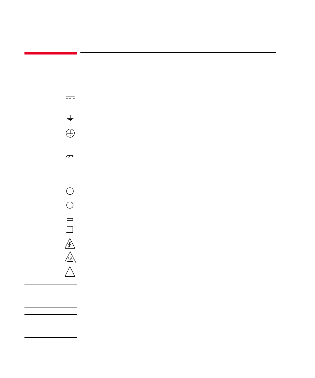
Safety Symbols
>
^
The general definitions of safety symbols used on equipment or in manuals are listed
below.
Direct current.
Alternating current.
Earth (ground) terminal.
Protective conductor terminal. For protection against electrical shock in case of a fault.
Used with field wiring terminals to indicate the terminal which must be connected to
ground before operating equipment.
Frame or chassis terminal. A connection to the frame (chassis) of the equipment which
normally includes all exposed metal structures.
Grounded terminal which indicates the earth potential.
On supply.
Off supply.
Standby supply. The equipment will be marked with this symbol is not completely
disconnected from AC mains when power switch is in the standby position.
In position of a bi-stable push switch.
Out position of a bi-stable push switch.
Hazardous voltage and potential for electrical shock. Do not touch terminals that have
this symbol when the equipment is on.
Hot surface. Avoid contact. Surfaces are hot and may cause personal injury if touched.
Caution, refer to accompanying documentation. The equipment will be marked with this
symbol when it is necessary for the user to refer to the instruction manual.
WARNING The warning sign denotes a hazard. It call s attention to a procedure, practice, cond ition
or the like, which, if not correctly performed or adhered to, could result in injury or
death to personal.
CAUTION The caution sign denotes a hazard. It calls attention to an operating procedure, practice,
condition or the like, which, if not correctly performed or adhered to, could result in
damage to or destruction of part or all of the equipment.
Page 11

IEC Measurement Category I
CAT I
The CE mark shows that the product complies with all applicable European Directives.
The CSA mark is a registered trademark of the Canadian Standards Association.
The RCM mark is a registered trademark of the Australian Communications Authority. This
signifies compliance with the Australian EMC Framework Regulations under the terms of
the Radio communications Act.
This ISM device complies with Canadian ICES-001.
Cet appareil ISM est conforme à la norme NMB-001 du Canada.
This is the symbol for an Industrial, Scientific and Medical, Group 1 Class A product.
(CISPR 11)
Korea’s safety and EMC mark
China RoHS - Environmentally Green Product Label
China RoHS - Product with Toxic Substance 40 yr EPUP
The Chinese mark for paper-based packaging materials; Paperboard and Corrugated
Fiberboard
Plastic Material Coding Identification
Page 12

Power Supply and Measurement Safety
• Power Supply Safety
This instrument can output high currents and voltages. Make sure that the load or
device under test can safely handle the output current and voltage. Also, make sure
that the connection leads can safely withstand the expected currents and are
insulated for the expected voltages.
The instrument outputs may be connected so as to float relative to earth ground.
Isolation or floating voltage ratings are indicated on the instrument, near the output
terminal or the Circuit Common terminal. There is the danger of electric shock by
touching the floated measurement terminals. Keep in mind it to protect yourself. And
it is a reason of using the recommended accessories.
• Voltage/Current Measurement Safety
Multimeters and other instruments capable of measuring high voltages and currents
are subject to specific safety concerns because of the circuits to which they may be
connected. To safely use these instruments, you need to understand the markings on
the instrument near the input terminals, which include the Protection Limits and the
IEC Measurement Category.
• Protection Limits
Keysight multimeters and other voltage measurement instruments provide protection
circuitry to prevent damage to the instrument and to protect against the danger of
electric shock, provided the Protection Limits are not exceeded. To ensure safe
operation of the instrument, do not exceed the Protection Limits shown on the input
terminals.
• Source/Monitor Terminals
Source/monitor unit, SMU, can simultaneously perform DC voltage or current output
and measurement. Typical SMU has the Force, Guard, Sense, and Circuit Common
terminals as shown below. Normally the Force, Guard, and Sense terminals are the
same potential. Voltage marked around the terminals indicates the Protection Limits.
Force and Sense must be connected to a terminal of a device under test for the Kel vin
connection which is effective for high current measurement and low resistance
measurement. For the non-Kelvin connection to ease the connections, connect Force
only. Do not connect Sense. It must be opened.
Page 13

Guard should be extended to around the device terminal for reducing leakage current
Force
Sense
Guard
Circuit Common
Guard
1.E- 09
1.E- 08
1.E- 07
1.E- 06
100 1000 10000
Capac itance ( F)
Volt age ( V)
Safety Area
Q=45 μC
C=0.1 μF
(Based on standards IEC60950-1 and IEC61010-1.)
caused by a coaxial cable used. Guard must be never connected to anything at the
device side.
Circuit Common should be connected to shielding of the coaxial cable used.
The following image is the Kelvin triaxial connector of Medium Power SMU.
• To Avoid Risk of Residual Charge
This graph shows the load capacitance vs voltage characteristics generally
considered as safety. Use the instrument within the safety area up to 0.1 F or 45 C
according to the voltage. Also do not connect the capacitive load over the maximum
load capacitance specified for the instrument, for example 10 nF for HVSMU.
Before touching the measurement terminal, confirm that it has been discharged
enough. For that, ground and discharge the terminals over 10 seconds after stopping
the high voltage output, and confirm that they have been safety voltage by using
another volt meter.
If abnormal end of measurement, breaking of cable, or device damage occurs, do not
touch the terminals until they are discharged enough.
Also if a series resistor is connected, do not touch the terminal until it is discharged
enough.
Page 14

High Voltage Shock Hazard
Keysight B1507A can force dang erou s vo l tages (±3000 Vdc for HVSMU and ±100
Vdc for MPSMU) at the Force, Guard, and Sense terminals. To prevent electric
shock hazard, the following safety precautions must be observed during the use of
Keysight B1507A.
• Connect the instrument to an electrical ground (safety ground) by using
three-conductor AC power cable.
• Before performing measurement, connect the interlock circuit to the Interlock
terminal of this instrument.
• Confirm periodically that the interlock function works normally.
• Before touching the connections of the Force, Guard, and Sense terminals, turn
the instrument off and discharge any capacitors of the measuremen t path. If you
do not turn the instrument off, complete “all” of the following items, regardless
of any instrument settings.
• Terminate measurement by pressing the Stop key, confirm that the
Measurement status indicator is not lit.
• Confirm that the High Voltage indicator is not lit.
• Open the Interlock terminal.
• Discharge any capacitors if the capacitance is connected to an SMU.
• Warn workers in the vicinity of the instrument about hazardous conditions.
Page 15

Gefahr durch Hochspannung
Von den Geräten Keysight B1507A können Spannungen an den Anschlüssen
“Force”, “Guard” und “Sense” von bis zu 3000 V ausgehen. Um elektrischem
Schlag vorzubeugen, ist bei der Benützung der Geräte Keysight B1507A folgendes
zu beachten.
• Verwenden Sie ein dreiphasiges AC-Stromkabel für die Gerätsteckvorrichtung
(Eingang) und schließen Sie das Instrument an eine Erdung an
(Sicherheitserdung).
• Vor der Messung verbinden Sie den Verriegelungsstromkreis mit dem
Interlock-Anschlus s dieses Inst ru ments .
• Prüfen Sie in regelmäßigen Abständen, dass die Verriegelungsfunktion
ordnungsgemäß funktioniert.
• Bevor S ie die Verbindungen zu den Anschlüssen “Force”, “Guard” und “Sense”
berühren, schalten Si e das Instrume nt aus und entladen alle Kondensatoren des
Messwegs. Wenn Sie das Instrument nicht ausschalten, führen Sie, unabhängig
von den Instrumenteinstellungen, alle folgenden Schritte durch.
• Beenden Sie die Messung, indem Sie auf die Taste “Stop” drücken. Stellen
Sie sicher, dass die Statusanzeige “Measurement” nicht leuchtet.
• Stellen Sie sicher, dass die Anzeige “High Voltage” nicht leuchtet.
• Öffnen des Interlock-Anschlusses.
• Entladen Sie alle Kondensatoren, wenn die Kapazität mit einer SMU
verbunden i st.
• Warnen Sie Mitarbeiter in der Umgebung des Instruments vor den Gefahren.
Page 16

Danger de choc dû à une haute tens ion
Une tension dangereuse (max. ± pour HVSMU; 3000 Vdc, max. ± pour MPSMU;
100 Vdc) émanant du dispositif Keysight B1507A peut être sortie aux bornes Force,
Guard et Sense. Les précautions suivantes doivent être obserées contre commotion
électrique accidentelle.
• Utilisez un câble d’alimentation CA à trois conducteurs vers le coupleur secteur
(entrée) et branchez l’instrument sur une mise électrique à la terre (prise de terre
de sécurité).
• Avant de procéder aux mesures, connectez le circuit de sécurité à la borne
Interlock de l’instrument.
• Vérifiez régulièrement le bon fonctionnement de la fonction de sécurité.
• Avant de toucher les connexions des bornes Force, Guard et Sense, mettez
l’instrument hors tension et déchargez tout condensateur du chemin de mesure.
Si vous ne mettez pas l’instrument hors tension, effectuez « toutes » les
opérations ci-dessous, quels que soient les paramètres de l’instrument.
• Terminez les mesures en appuyant sur la touche Stop ; vérifiez que
l’indicateur d’état Measurement est éteint.
• Vérifiez que le témoin High Voltage est éteint.
• Ouvrez la borne Interlock.
• Déchargez les éventuels condensateurs si la capacité est connectée à une
unité SMU.
• Informez les personnes travaillant à proximité de l’instrument des conditions.
Page 17

高電圧感電注意
Keysight B1507A の Force、Guard、Sense 端子には、危険電圧が出力されることがあ
ります(
事故防止のため、
•3 極電源ケーブルを使用して本器を接地してください。
• 測定を開始する前にはインターロック回路を本器の Interlock 端子に接続してく
• インターロック機能が正常であることを定期的に確認してください。
•Force、Guard、Sense 端子に繋がる接続部に触れる前には、本器の電源をオフし
• 周囲のほかの作業者に対しても、高電圧危険に対する注意を徹底してください。
HVSMU の場合は最大 ±3000 Vdc、MPSMU の場合は最大 ±100 Vdc)。感電
Keysight B1507A の使用時には必ず以下の事柄を守ってください。
ださい。
てください。また、測定系のキャパシタを放電してください。電源を
い場合は、以下の事項を全て実施してください。
• Stop キーを押して Measurement インジケータが消灯したことを確認してくだ
さい。
• 高電圧警告(High Voltage)インジケータが消灯していることを確認してく
ださい。
•Interlock 端子を開放してください。
• キャパシタが SMU に接続されているならば、キャパシタを放電してくださ
い。
オフしな
Page 18

Product Stewardship
• Waste Electrical and Electronic Equipment (WEEE) Directive 2002/96/EC
This product complies with the WEEE Directive (2002/96/EC) marking requirements.
The affixed label indicates that you must not discard this electrical/ electronic
product in domestic household waste.
Product Category: With reference to the equipment types in the WEEE directive
Annex 1, this product is classified as a “Monitoring and Control instrumentation”
product.
Do not dispose in domestic household waste.
To return unwanted products, contact your local Keysight office or visit the following
website for more information.
http://about.keysight.com/en/companyinfo/environment/
•LCD Fluorescent Lamp
Certain products sold by Keysight contain a liquid crystal display (LCD); backlighting
for the LCD is provided by a fluorescent lamp which contains mercury, and must be
managed, recycled, and/or disposed in accordance with all applicable laws,
ordinances and regulations.
For information on how to recycle or dispose of the fluorescent lamp contained in
your own product, visit the following website.
http://about.keysight.com/en/quality/env_compliance.shtml
If you live in the U.S., also visit the following websites.
http://www.lamprecycle.org
http://www.eiae.org
If you have additional questions, please visit the following website.
http://www.keysight.com/go/contactus
•Perchlorate Information
Perchlorate Material - special handling may apply. Visit the following website.
http://www.dtsc.ca.gov/hazardouswaste/perchlorate/
Equipment's real-time clock battery or coin cell battery may contain perchlorate and
may require special handling when recycled or disposed of in California.
Page 19

Precautionary Statement
Keysight B1507A Power Device Capacitance Analyzer operates in the Microsoft Windows
environment. Keysight B1507A requires Keysight Easy Test Navigator software, a
specially-designed Windows application program.
• About guarantee and support for Keysight B1507A
Keysight Technologies guarantees and supports the performance of Keysight B1507A
for the same condition as the preload condition when shipped from the factory.
• About updating Keysight Easy Test Navigator and the Windows Update
Keysight Technologies confirms the operation of Easy Test Navigator patch programs
and important Windows security patches, and provides recommended update
information. Visit Keysight B1507A support site, download the patches, and perform
the software update.
• About Windows application programs and peripherals (including driver)
Using commercial products on Keysight B1507A is your responsibility. Keysight
Technologies cannot provide compatibility information for commercial products. If
problems arise, perform Keysight B1507A system recovery.
•About servicing
Bench repair service is available at your nearest Keysight Technologies service
center. Be aware that the B1507A configuration might be updated to the latest one
without notice because of support issues.
The internal hard disk drive (HDD) might be initialized during servicing. If peripherals
are connected, they will be removed.
When Keysight B1507A is returned, the internal HDD might be initialized. Peripherals
will be returned separately.
•Other notes
• Back up the internal HDD to prevent loss of data by accident or failure.
• Protect Keysight B1507A from computer viruses.
• If you connect Keysight B1507A to the network, take care to protect it from
computer virus.
Page 20

Working in Comfort
To optimize your comfort and productivity, it is important that you set up your work area
correctly and use your instrument properly. With that in mind, we have developed some
set-up and use recommendations for you to follow based on established ergonomic
principles. Improper and prolonged use of keyboards and input devices are among those
tasks that have been associated with repetitive strain injury (RSI) to soft tissues in the
hands and arms. If you experience discomfort or pain while using the instrument,
discontinue use immediately and consult your physician as soon as possible. For more
information on RSI you may wish to consult the About Repetitive Strain Injury section.
Please study the recommendations described below. Included there are references to
relevant parts of international standards, regulations and guidelines, such as ISO 9241
and the European Community Display Screen Equipment directive. You may also wish to
consult your employer’s human resources department or other relevant departments for
guidance specific to your company.
About Repetitive Strain Injury
Because your comfort and safety are our primary concern, we strongly recommend that
you use the instrument in accordance with established ergonomic principles and
recommendations. Scientific literature suggests that there may be a relationship between
injury to soft tissues -especially in the hands and arms- and prolonged improper use of
keyboards or other equipment requiring repeated motions of the hands and forearms.
This literature also suggests that there are many other risk factors that may increase the
chance of such injury, commonly called Repetitive Strain Injury.
What is RSI?
Repetitive Strain Injury (RSI -also known as cumulative trauma disorder or repetitive
motion injury) is a type of injury where soft tissues in the body, such as muscles, nerves,
or tendons, become irritated or inflamed. RSI has been a reported problem for those who
perform repetitive tasks such as assembly line work, meatpacking, sewing, playing
musical instruments, and computer work. RSI also has been observed in those who
frequently engage in activities such as carpentry, knitting, housework, gardening, tennis,
windsurfing and lifting children.
What causes RSI?
The specific causes of RSI have not been established. Nevertheless, the incidence of RSI
has been associated with a variety of risk factors, including:
• Too many uninterrupted repetitions of an activity or motion.
• Performing an activity in an awkward or unnatural posture.
Page 21

• Maintaining static posture for prolonged periods.
• Failing to take frequent short breaks.
• Other environmental and psychosocial factors.
In addition, there have been reports associating the occurrence of RSI with the use of
keyboards, mice, and other input devices. Also, certain medical conditions, such as
rheumatoid arthritis, obesity and diabetes, may predispose some people to this type of
injury.
What if I experience discomfort?
If you are experiencing any discomfort, seek professional medical advice immed iately.
Typically, the earlier a problem is diagnosed and treated, the easier it is to resolve.
Mice and Other Input Devices
Various aspects of using mice and other input devices may increase your risk of
discomfort or injury. Observing the following recommendations may reduce that risk.
• Try to keep your hand, wrist, and forearm in a neutral position while using your mouse
or other input device.
• If you use your thumb to rotate the ball on a trackball or spaceball, keep it in a
relaxed, natural shape, and maintain a neutral posture in your hand, wrist, and
forearm.
• Hold the mouse gently by draping your fingers over it. Keep your hand relaxed and
fingers loose. Do not grip the mouse tightly.
• It takes very little pressure or force from your fingers to activate the buttons or scroll
wheel on your mouse, scrolling mouse, trackball, or other input device. Using too
much force can place unnecessary stress on the tendons and muscles in your hands,
wrists, and forearms.
• If you are using a scrolling mouse, be sure to keep your fingers and hand in a relaxed,
neutral position when activating the scroll wheel. Also, this type of mouse features
software that can minimize the number of mouse movements or button clicks.
• When using a mouse, trackball, or other input device, position it as close to the
keyboard as possible, and keep it at the same level as you do not have to stretch while
using it.
• Be sure to keep your mouse and trackball clean. Regular removal of accumulated
dust and dirt helps ensure proper tracking and reduces unnecessary hand and wrist
motions.
Page 22

In This Manual
This manual describes the product overview, installation information, measurement
operation, and software reference information of Keysight Technologies B1507A.
This manual consists of the following chapters:
• Chapter 1, “Introduction”
This chapter describes basic features of Keysight B1507A.
• Chapter 2, “Installation”
This chapter describes installation and maintenance.
• Chapter 3, “How To Perform Measurement”
This chapter explains how to perform measurement by using Keysight B1507A.
• Chapter 4, “GUI Reference”
This chapter provides the reference information of Keysight Easy Test Navigator
software.
Page 23

Contents
1. Introduction
Overview . . . . . . . . . . . . . . . . . . . . . . . . . . . . . . . . . . . . . . . . . . . . . . . . . . . . . . . . . . . . . . . . 1-3
Mainframe . . . . . . . . . . . . . . . . . . . . . . . . . . . . . . . . . . . . . . . . . . . . . . . . . . . . . . . . . . . . . 1-4
Test Fixture and Selector . . . . . . . . . . . . . . . . . . . . . . . . . . . . . . . . . . . . . . . . . . . . . . . . . 1-4
Mainframe Front View. . . . . . . . . . . . . . . . . . . . . . . . . . . . . . . . . . . . . . . . . . . . . . . . . . . . . .1-5
Mainframe Rear View . . . . . . . . . . . . . . . . . . . . . . . . . . . . . . . . . . . . . . . . . . . . . . . . . . . . . . 1-8
. . . . . . . . . . . . . . . . . . . . . . . . . . . . . . . . . . . . . . . . . . . . . . . . . . . . . . . . . . . . . . . . . . . . . 1-8
. . . . . . . . . . . . . . . . . . . . . . . . . . . . . . . . . . . . . . . . . . . . . . . . . . . . . . . . . . . . . . . . . . . . 1-10
. . . . . . . . . . . . . . . . . . . . . . . . . . . . . . . . . . . . . . . . . . . . . . . . . . . . . . . . . . . . . . . . . . . . 1-11
Test Fixture Front View. . . . . . . . . . . . . . . . . . . . . . . . . . . . . . . . . . . . . . . . . . . . . . . . . . . . 1-12
. . . . . . . . . . . . . . . . . . . . . . . . . . . . . . . . . . . . . . . . . . . . . . . . . . . . . . . . . . . . . . . . . . . . 1-12
Measurement Terminals. . . . . . . . . . . . . . . . . . . . . . . . . . . . . . . . . . . . . . . . . . . . . . . . . 1-13
. . . . . . . . . . . . . . . . . . . . . . . . . . . . . . . . . . . . . . . . . . . . . . . . . . . . . . . . . . . . . . . . . . 1-13
Test Fixture Rear View . . . . . . . . . . . . . . . . . . . . . . . . . . . . . . . . . . . . . . . . . . . . . . . . . . . . 1-15
. . . . . . . . . . . . . . . . . . . . . . . . . . . . . . . . . . . . . . . . . . . . . . . . . . . . . . . . . . . . . . . . . . . . 1-15
. . . . . . . . . . . . . . . . . . . . . . . . . . . . . . . . . . . . . . . . . . . . . . . . . . . . . . . . . . . . . . . . . . . . 1-16
Software. . . . . . . . . . . . . . . . . . . . . . . . . . . . . . . . . . . . . . . . . . . . . . . . . . . . . . . . . . . . . . . .1-17
Easy Test Navigator Software . . . . . . . . . . . . . . . . . . . . . . . . . . . . . . . . . . . . . . . . . . . . 1-17
EasyEXPERT Software. . . . . . . . . . . . . . . . . . . . . . . . . . . . . . . . . . . . . . . . . . . . . . . . . . .1-18
Utility Software. . . . . . . . . . . . . . . . . . . . . . . . . . . . . . . . . . . . . . . . . . . . . . . . . . . . . . . . 1-18
Accessories . . . . . . . . . . . . . . . . . . . . . . . . . . . . . . . . . . . . . . . . . . . . . . . . . . . . . . . . . . . . . 1-20
Options. . . . . . . . . . . . . . . . . . . . . . . . . . . . . . . . . . . . . . . . . . . . . . . . . . . . . . . . . . . . . . . . .1-22
Measurement Resources . . . . . . . . . . . . . . . . . . . . . . . . . . . . . . . . . . . . . . . . . . . . . . . . . . 1-23
GNDU - Ground Unit. . . . . . . . . . . . . . . . . . . . . . . . . . . . . . . . . . . . . . . . . . . . . . . . . . . .1-23
About SMU . . . . . . . . . . . . . . . . . . . . . . . . . . . . . . . . . . . . . . . . . . . . . . . . . . . . . . . . . . . 1-24
MPSMU - Medium Power SMU. . . . . . . . . . . . . . . . . . . . . . . . . . . . . . . . . . . . . . . . . . .1-25
HVSMU - High Voltage SMU . . . . . . . . . . . . . . . . . . . . . . . . . . . . . . . . . . . . . . . . . . . . . 1-28
MFCMU - Multi Frequency CMU. . . . . . . . . . . . . . . . . . . . . . . . . . . . . . . . . . . . . . . . . . 1-30
Keysight B1507A User’s Guide, Edition 1
Page 24

Contents
2. Installation
. . . . . . . . . . . . . . . . . . . . . . . . . . . . . . . . . . . . . . . . . . . . . . . . . . . . . . . . . . . . . . . . . . . . .
. . . . . . . . . . . . . . . . . . . . . . . . . . . . . . . . . . . . . . . . . . . . . . . . . . . . . . . . . . . . . . . . . . . . .2-3
Requirements . . . . . . . . . . . . . . . . . . . . . . . . . . . . . . . . . . . . . . . . . . . . . . . . . . . . . . . . . . . .2-4
Power Requirements . . . . . . . . . . . . . . . . . . . . . . . . . . . . . . . . . . . . . . . . . . . . . . . . . . . .2-4
Operating Environment . . . . . . . . . . . . . . . . . . . . . . . . . . . . . . . . . . . . . . . . . . . . . . . . . .2-4
Storaging/Shipping Environment . . . . . . . . . . . . . . . . . . . . . . . . . . . . . . . . . . . . . . . . . .2-4
Installation Requirements. . . . . . . . . . . . . . . . . . . . . . . . . . . . . . . . . . . . . . . . . . . . . . . . .2-5
. . . . . . . . . . . . . . . . . . . . . . . . . . . . . . . . . . . . . . . . . . . . . . . . . . . . . . . . . . . . . . . . . . .2-5
Power Cable. . . . . . . . . . . . . . . . . . . . . . . . . . . . . . . . . . . . . . . . . . . . . . . . . . . . . . . . . . . .2-6
. . . . . . . . . . . . . . . . . . . . . . . . . . . . . . . . . . . . . . . . . . . . . . . . . . . . . . . . . . . . . . . . . . .2-6
Inspection and Installation . . . . . . . . . . . . . . . . . . . . . . . . . . . . . . . . . . . . . . . . . . . . . . . . . .2-8
To Inspect Shipment. . . . . . . . . . . . . . . . . . . . . . . . . . . . . . . . . . . . . . . . . . . . . . . . . . . . .2-8
To Perform Initial Setup . . . . . . . . . . . . . . . . . . . . . . . . . . . . . . . . . . . . . . . . . . . . . . . . . .2-9
To Connect Selector and Test Fixture . . . . . . . . . . . . . . . . . . . . . . . . . . . . . . . . . . . . . 2-11
. . . . . . . . . . . . . . . . . . . . . . . . . . . . . . . . . . . . . . . . . . . . . . . . . . . . . . . . . . . . . . . . . 2-11
To Check Operation of Selector . . . . . . . . . . . . . . . . . . . . . . . . . . . . . . . . . . . . . . . . . . 2-13
To Change Windows Logon Setting. . . . . . . . . . . . . . . . . . . . . . . . . . . . . . . . . . . . . . . 2-13
To Change GPIB Address . . . . . . . . . . . . . . . . . . . . . . . . . . . . . . . . . . . . . . . . . . . . . . . 2-14
To Enable System Controller . . . . . . . . . . . . . . . . . . . . . . . . . . . . . . . . . . . . . . . . . . . . 2-15
2-2
Connecting Accessories . . . . . . . . . . . . . . . . . . . . . . . . . . . . . . . . . . . . . . . . . . . . . . . . . . 2-16
. . . . . . . . . . . . . . . . . . . . . . . . . . . . . . . . . . . . . . . . . . . . . . . . . . . . . . . . . . . . . . . . . . . 2-16
3-pin Inline Package Socket Module. . . . . . . . . . . . . . . . . . . . . . . . . . . . . . . . . . . . . . 2-17
. . . . . . . . . . . . . . . . . . . . . . . . . . . . . . . . . . . . . . . . . . . . . . . . . . . . . . . . . . . . . . . . . 2-17
Accessories for Connecting a DUT. . . . . . . . . . . . . . . . . . . . . . . . . . . . . . . . . . . . . . . . 2-18
. . . . . . . . . . . . . . . . . . . . . . . . . . . . . . . . . . . . . . . . . . . . . . . . . . . . . . . . . . . . . . . . . 2-18
Maintenance. . . . . . . . . . . . . . . . . . . . . . . . . . . . . . . . . . . . . . . . . . . . . . . . . . . . . . . . . . . . 2-19
Cleaning . . . . . . . . . . . . . . . . . . . . . . . . . . . . . . . . . . . . . . . . . . . . . . . . . . . . . . . . . . . . . 2-19
Self-test and Diagnosis. . . . . . . . . . . . . . . . . . . . . . . . . . . . . . . . . . . . . . . . . . . . . . . . . 2-19
. . . . . . . . . . . . . . . . . . . . . . . . . . . . . . . . . . . . . . . . . . . . . . . . . . . . . . . . . . . . . . . . . 2-19
Keysight B1507A User’s Guide, Ed ition 1
Page 25

Contents
Calibration. . . . . . . . . . . . . . . . . . . . . . . . . . . . . . . . . . . . . . . . . . . . . . . . . . . . . . . . . . . .2-19
Before Shipping to Service Center . . . . . . . . . . . . . . . . . . . . . . . . . . . . . . . . . . . . . . . . . . 2-20
To Make Backup . . . . . . . . . . . . . . . . . . . . . . . . . . . . . . . . . . . . . . . . . . . . . . . . . . . . . . . 2-20
To Check Module Slots . . . . . . . . . . . . . . . . . . . . . . . . . . . . . . . . . . . . . . . . . . . . . . . . .2-20
To Collect Equipment and Accessories. . . . . . . . . . . . . . . . . . . . . . . . . . . . . . . . . . . . . 2-20
. . . . . . . . . . . . . . . . . . . . . . . . . . . . . . . . . . . . . . . . . . . . . . . . . . . . . . . . . . . . . . . . . . 2-20
3. How To Perform Measurement
How To Perform Capacitance Measurement . . . . . . . . . . . . . . . . . . . . . . . . . . . . . . . . . . .3-3
Preparing Measurement. . . . . . . . . . . . . . . . . . . . . . . . . . . . . . . . . . . . . . . . . . . . . . . . . . 3-4
Executing Measurement. . . . . . . . . . . . . . . . . . . . . . . . . . . . . . . . . . . . . . . . . . . . . . . . . . 3-5
Setting Parameters. . . . . . . . . . . . . . . . . . . . . . . . . . . . . . . . . . . . . . . . . . . . . . . . . . . . . . 3-8
How To Perform I/V Measurement . . . . . . . . . . . . . . . . . . . . . . . . . . . . . . . . . . . . . . . . . . . 3-9
Preparing Measurement. . . . . . . . . . . . . . . . . . . . . . . . . . . . . . . . . . . . . . . . . . . . . . . . .3-10
Executing Measurement. . . . . . . . . . . . . . . . . . . . . . . . . . . . . . . . . . . . . . . . . . . . . . . . . 3-11
Setting Parameter. . . . . . . . . . . . . . . . . . . . . . . . . . . . . . . . . . . . . . . . . . . . . . . . . . . . . . 3-17
How To Calculate Power Loss . . . . . . . . . . . . . . . . . . . . . . . . . . . . . . . . . . . . . . . . . . . . . . 3-18
Calculating Power Loss . . . . . . . . . . . . . . . . . . . . . . . . . . . . . . . . . . . . . . . . . . . . . . . . . 3-19
Extracted Parameters By Power Loss Calculation . . . . . . . . . . . . . . . . . . . . . . . . . . . . 3-25
Displaying and Operating Graph . . . . . . . . . . . . . . . . . . . . . . . . . . . . . . . . . . . . . . . . . . . . 3-26
How To Select and Display Characteristics Curve. . . . . . . . . . . . . . . . . . . . . . . . . . . .3-26
How To Use the Marker . . . . . . . . . . . . . . . . . . . . . . . . . . . . . . . . . . . . . . . . . . . . . . . . .3-27
4. GUI Reference
Software Palette . . . . . . . . . . . . . . . . . . . . . . . . . . . . . . . . . . . . . . . . . . . . . . . . . . . . . . . . . . 4-3
Capacitance Measurement Software . . . . . . . . . . . . . . . . . . . . . . . . . . . . . . . . . . . . . . . . . 4-4
GUI Overview. . . . . . . . . . . . . . . . . . . . . . . . . . . . . . . . . . . . . . . . . . . . . . . . . . . . . . . . . . .4-5
Main Menu. . . . . . . . . . . . . . . . . . . . . . . . . . . . . . . . . . . . . . . . . . . . . . . . . . . . . . . . . . . . . 4-6
Toolbar. . . . . . . . . . . . . . . . . . . . . . . . . . . . . . . . . . . . . . . . . . . . . . . . . . . . . . . . . . . . . . . . 4-9
Keysight B1507A User’s Guide, Edition 1
Page 26

Contents
Work Area. . . . . . . . . . . . . . . . . . . . . . . . . . . . . . . . . . . . . . . . . . . . . . . . . . . . . . . . . . . . 4-11
Data List . . . . . . . . . . . . . . . . . . . . . . . . . . . . . . . . . . . . . . . . . . . . . . . . . . . . . . . . . . . . . 4-28
Dialog Boxes . . . . . . . . . . . . . . . . . . . . . . . . . . . . . . . . . . . . . . . . . . . . . . . . . . . . . . . . . 4-30
Summary of Files. . . . . . . . . . . . . . . . . . . . . . . . . . . . . . . . . . . . . . . . . . . . . . . . . . . . . . 4-31
I/V Measurement Software. . . . . . . . . . . . . . . . . . . . . . . . . . . . . . . . . . . . . . . . . . . . . . . . 4-32
GUI Overview . . . . . . . . . . . . . . . . . . . . . . . . . . . . . . . . . . . . . . . . . . . . . . . . . . . . . . . . . 4-33
Main Menu . . . . . . . . . . . . . . . . . . . . . . . . . . . . . . . . . . . . . . . . . . . . . . . . . . . . . . . . . . . 4-34
Toolbar . . . . . . . . . . . . . . . . . . . . . . . . . . . . . . . . . . . . . . . . . . . . . . . . . . . . . . . . . . . . . . 4-36
Work Area. . . . . . . . . . . . . . . . . . . . . . . . . . . . . . . . . . . . . . . . . . . . . . . . . . . . . . . . . . . . 4-38
Data List . . . . . . . . . . . . . . . . . . . . . . . . . . . . . . . . . . . . . . . . . . . . . . . . . . . . . . . . . . . . . 4-57
Dialog Boxes . . . . . . . . . . . . . . . . . . . . . . . . . . . . . . . . . . . . . . . . . . . . . . . . . . . . . . . . . 4-59
Summary of Files. . . . . . . . . . . . . . . . . . . . . . . . . . . . . . . . . . . . . . . . . . . . . . . . . . . . . . 4-60
Power Loss Calculation Software. . . . . . . . . . . . . . . . . . . . . . . . . . . . . . . . . . . . . . . . . . . 4-61
GUI Overview . . . . . . . . . . . . . . . . . . . . . . . . . . . . . . . . . . . . . . . . . . . . . . . . . . . . . . . . . 4-62
Main Menu . . . . . . . . . . . . . . . . . . . . . . . . . . . . . . . . . . . . . . . . . . . . . . . . . . . . . . . . . . . 4-63
Toolbar . . . . . . . . . . . . . . . . . . . . . . . . . . . . . . . . . . . . . . . . . . . . . . . . . . . . . . . . . . . . . . 4-65
Work Area. . . . . . . . . . . . . . . . . . . . . . . . . . . . . . . . . . . . . . . . . . . . . . . . . . . . . . . . . . . . 4-67
Data List . . . . . . . . . . . . . . . . . . . . . . . . . . . . . . . . . . . . . . . . . . . . . . . . . . . . . . . . . . . . . 4-74
Dialog Boxes . . . . . . . . . . . . . . . . . . . . . . . . . . . . . . . . . . . . . . . . . . . . . . . . . . . . . . . . . 4-76
Summary of Files. . . . . . . . . . . . . . . . . . . . . . . . . . . . . . . . . . . . . . . . . . . . . . . . . . . . . . 4-77
Common GUI Components. . . . . . . . . . . . . . . . . . . . . . . . . . . . . . . . . . . . . . . . . . . . . . . . 4-78
Module Configuration Dialog Box . . . . . . . . . . . . . . . . . . . . . . . . . . . . . . . . . . . . . . . . 4-78
Keysight B1507A User’s Guide, Ed ition 1
Page 27

1Introduction
Page 28

Introduction
This chapter describes the basic functions and features of Keysight B1507A Power
Device Capacitance Analyzer, and consists of the following sections.
• “Overview”
• “Mainframe Front View”
• “Mainframe Rear View”
• “Test Fixture Front View”
• “Test Fixture Rear View”
• “Software”
• “Accessories”
• “Options”
• “Measurement Resources”
1- 2 Keysight B1507A User’s Guide, Ed ition 1
Page 29

Introduction
Overview
Overview
Keysight B1507A Power Device Capacitance Analyzer provides a complete
solution for the evaluation of power device capacitance (such as input, output, and
reverse transfer capacitances). Intuitive GUI allows you to automatically measure
all capacitances under a wide range of operating voltages. In addition, it makes it
easy to switch back and forth between leakage tests (to verify the device is not
damaged) and capacitance measurements without having to do any recabling.
The B1507A can help identify
substandard devices under actual
circuit operating vol tage biases (up
to 3 kV). This is an ideal
complement to conventional IV test
equipment (such as curve tracers)
that do not have either capacitance
or leakage testing capabilities.
The furnished software presents the
user with an intuitive user interface
that makes it easy to characterize
devices without going through any
formal training. Integrat ed switching
circuitry within the test fixture
supports fully-automated testing,
with the ability to automatically
make the correct connections for all
types of capacitance measurements.
This includes the insertion of DC
blocking capacitors and AC
blocking resistors as we ll as mak i ng
the connections necessary for
correct gate and drain/collector
leakage measurements.
Unique plug-in style device test fixture socket adapter helps to eliminate cable
connection and other human-related errors.
The B1507A contains the mainframe, the test fixture, the connection cables, and the
control software. For the furnished accessories, see Table 1-1.
Keysight B1507A User’s Guide, Edition 1 1- 3
Page 30

Introduction
Overview
Mainframe
Mainframe is equipped with the measurement resources listed below, the 15-inch
touch screen LCD panel, hard disk drive, DVD drive, USB, LAN, GPIB, GPIO
interfaces, and so on. For more information on the measurement resources, see
“Measurement Resources” on page 1-23.
• HVSMU, high voltage source/monitor unit, 1 ea.
• MFCMU, multi frequency capacitance measurement unit, 1 ea.
• MPSMU, medium power source/monitor unit, 1 ea.
• GNDU, ground unit, 1 ea.
The B1507A provides an intuitive graphical user interface, touch screen LCD,
stylus pen, USB keyboard , an d USB mo use f or easy an d ef f ective m easu rement and
analysis on the Windows environment, and supports the following B1507A control
software. For more information, see “Software” on page 1-17.
• Easy Test Navigator software
• EasyEXPERT software
Test Fixture and Selector
The test fixture is required to connect your device under test (DUT). The following
furnished accessories are available.
• Socket module for connecting a 3-pin inline package device
• Accessories for connecting other type of device
• Connection wire
•Clip
• Banana pin adapter
The selector is connected between the mainframe and the tes t fi xtur e. A nd it is us ed
for switching the IV measurement and the CV measurement.
NOTE Selector may emit a noise sound during operation. However it is not abnormal
status.
1- 4 Keysight B1507A User’s Guide, Ed ition 1
Page 31

Mainframe Front View
1
5
12
6
7
8
9
10
11
4
2
3
This section describes the front view of the mainframe.
Introduction
Mainframe Front View
1. Standby switch
Turns on/off the mainframe. Pressing the button in the ON state makes it in the
standby state. The green LED lights when it is in the ON state.
NOTE
Opening measurement terminals
Open the measurement terminals at the device side when turning the B1507A on.
Also disconnect the device from the measurement terminals and open the
measurement terminals after the measurement. If you leave the connection with the
device, the device may be damaged by unexpected operations or charge-up of
measurement cables.
2. HDD access indicator
This green LED lights in the access status of HDD or DVD drive. Do not turn
the instrument off during this LED lights.
Keysight B1507A User’s Guide, Edition 1 1- 5
Page 32

Introduction
Mainframe Front View
3. LCD a djustment keys
LCD Off enables or disables the LCD panel. The green LED lights when the
LCD is disabled.
Four keys are available for adjusting brightness. Use + and - to adjust it and
then press Set to fix it. Pressing Cancel instead of Set cancels the adjustment.
4. USB interfaces
USB, 2 ports. For keyboard, mouse, and so on.
To remove USB devices from the instrument, use “Safely Remove Hardware”
on Windows taskbar . If it is not used, the instrument may cause the internal USB
communication error. If the error occurs, turn the instrument off and disconnect
the power cable from it. Leave it about 30 seconds before rebooting it, and
connect the power cable again, and then turn the instrument on.
5. LCD panel
15 inch TFT XGA display, 1024 768 resolution. Displays the W indows screen,
the B1507A control software window, and so on. Touch screen operation is
available when the Touch Panel Off indicator does not light.
To adjust the touch panel, use Microchip TSHARC Control Panel which is
opened by selecting Microchip TSHARC Control Panel from the Start menu.
6. Stop k ey
Stops the present measurement or source output immediately.
7. High voltage status indicator
This red LED lights when a source channel applies dangerous voltage.
8. Measurement status indicator
This green LED lights when a measurement channel performs measurement.
9. Rotary knob
Works on the execution environment of the B1507A control software. Rotating
the knob moves the marker on the graph, or increases/decreases/changes the
value in the active entry field. Pressing the knob sets or enters the value.
10. Softkeys
Seven softkeys are available for the B1507A control software. Used to select an
alternative for the entry field specified or the dialog box.
1- 6 Keysight B1507A User’s Guide, Ed ition 1
Page 33

Introduction
Mainframe Front View
11. DVD-R drive
For data backup, software update, and so on. With the option DR1, the drive is
changed to the DVD-ROM drive.
12. Touch Panel Off key
Works on the execution environment of the B1507A control software. Enables
or disables the touch screen operation. The green LED lights when the touch
screen is disabled.
Keysight B1507A User’s Guide, Edition 1 1- 7
Page 34
Introduction
Mainframe Rear View
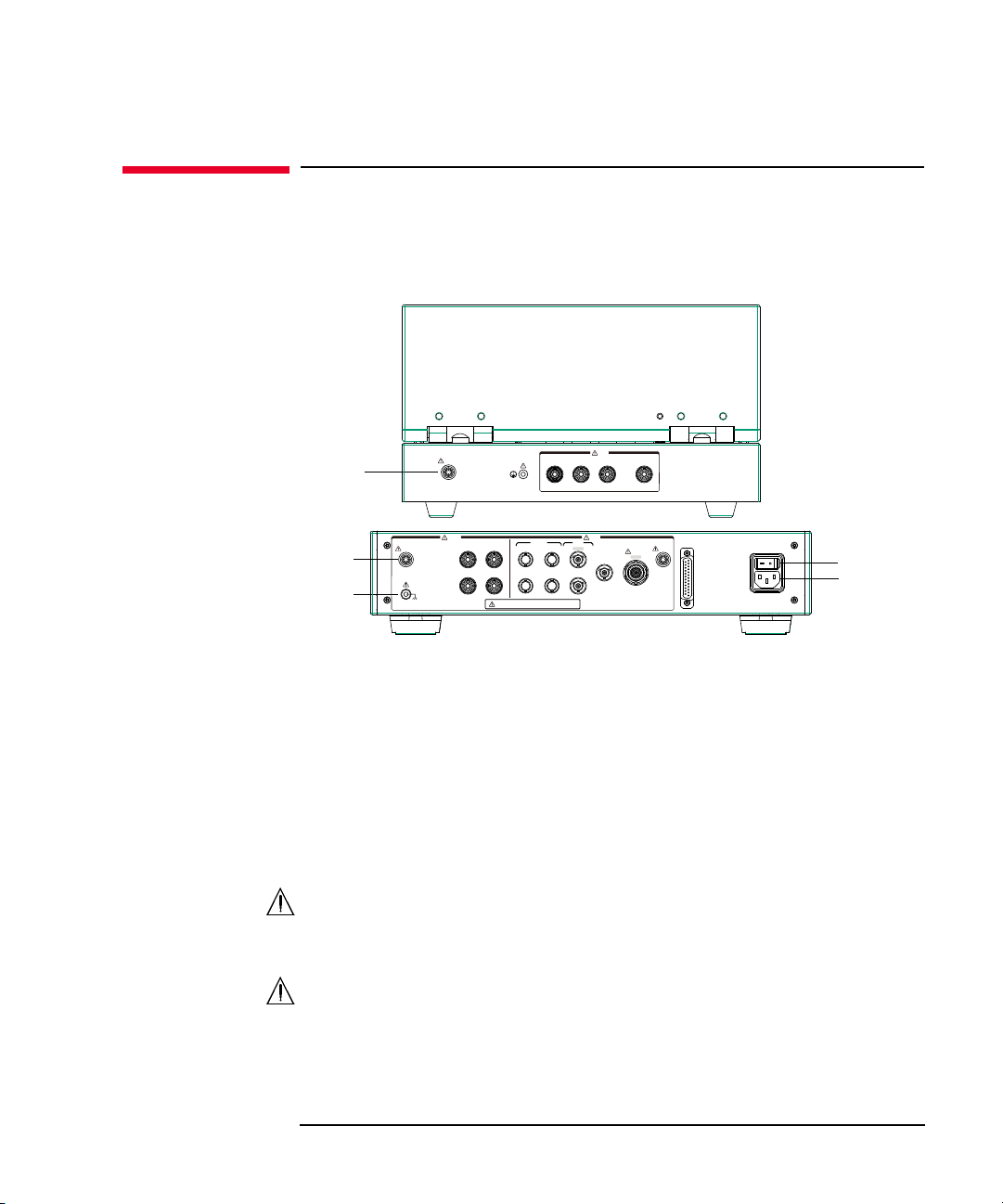
Mainframe Rear View
This section describes the rear view of the mainframe.
WARNING To avoid electrical shock and instrument damage, turn the all instruments off
before connecting or disconnecting measurement cable.
Mettez la machine hors tension pour fixer le connecteur ou pour retirer le
connecteur de l’unité centrale.
WARNING There are potentially hazardous voltages (± 3000 Vdc for HVSMU and ± 100
Vdc for MPSMU) present at the Force, Sense, and Guard terminals of the
instruments. To prevent electrical shock, the following safety precautions must
be observed during the use of instruments.
• Connect the instrument to an electrical ground (safety ground) by using
three-conductor AC power cable.
• Connect the mainframe Interlock terminal to the selector Interlock
terminal by using an interlock cable. Also connect the selector Interlock
terminal to the test fixture Interlock terminal by using an interlock cable.
• Confirm periodically that the interlock function works normally.
• Before touching the connections on the Force, Sense, and Guard terminals
in the test fixture, turn the instruments off and discharge any capacitors. If
you do not turn the instruments off, complete all of the following items,
regardless of the instrument settings.
• Press the front panel
• Confirm that the front panel High Voltage indicator is not lit.
• Open the Interlock terminal (open the fixture cover).
• Discharge any capacitors connected to a measurement resource.
• Warn persons working around the instrument about dangerous conditions.
1- 8 Keysight B1507A User’s Guide, Ed ition 1
Stop
key to set the source output off.
Page 35

Introduction
1
10
9
8
C
D
5
3
4
11
141213
7
2
B
A
6
Mainframe Rear View
1. Serial number
You need this serial number when using Keysight Technologies telephone
assistance program.
2. LED status indicator
For troubleshooting. Followings are some examples.
• Both LEDs turn off:
The instrument is in the standby state and Standby switch is OFF position.
• One LED turns green:
Power supply works normally.
• Both LEDs turn orange:
The instrument is in the standby state and Standby switch is ON position.
3. LINE input receptacle
AC power cable is connected to this receptacle.
Keysight B1507A User’s Guide, Edition 1 1- 9
Page 36

Introduction
Mainframe Rear View
4. GPIB interface
Use an Keysight 82357A USB/GPIB interface or Keysight 10833A/B/C/D
GPIB cable to connect to an external computer or equipment.
5. Video output terminal
VGA connector. For an external display. Signal to the built-in LCD is also
applied to this terminal.
6. Measurement Resources
See A to D described later.
7. Circuit Common ( ) and frame ground ( ) terminals
Normally, connect the terminals together by using the shorting bar. For floating
measurement, remove the shorting bar.
WARNING If the Circuit Common terminal is not connected to the frame ground terminal
(for floating measurement), a potential shock hazard may present. Do not
touch any of measurement circuit at any time while a floating measurement is
in progress.
CAUTION For floating measurement, do not apply dangerous voltage to the Circuit Common
terminal. Failure to heed this caution may result in damage to the instrument.
8. Zero Check terminal
Ground reference point of the instrument.
CAUTION The Zero Check terminal can be used for the service purpose only. For the normal
operation, leave this terminal open and do not connect anything to this terminal.
Connecting anything can damage the instrument.
9. GNDU terminal
0 V constant voltage source. Used for the reference of measurement ground.
Triaxial connector.
10. LAN interface
RJ45 connector.
11. USB interfaces
USB, 2 ports. For keyboard, mouse, or peripherals.
1- 10 Keysight B1507A User’s Guide, Ed ition 1
Page 37

Introduction
Mainframe Rear View
To remove USB devices from the instrument, use “Safely Remove Hardware”
on Windows taskbar. If it is not used, the instrument may cause the internal USB
communication error.
If the error occurs, turn the instrument off and disconnect the power cable from
it. Leave it about 30 seconds before rebooting it, and connect the power cable
again, and then turn the instrument on.
12. Ext Trig terminals
Two BNC connectors, one for trigger input, and one for trigger output. For
details about the trigger function, see Programming Guide.
13. Digital I/O terminal
Used to connect the test fixture.
14. Interlock terminal
Used to connect the test fixture. If the fixture cover is open, maximum output is
limited to ±42 V.
To verify the interlock function, perform the Interlock Open/Close test on the
Main Frame tab screen of the EasyEXPERT Configuration window.
WARNING Dangerous voltage, i nstru me nt m ax imum ou tp ut vol t age m ay ap pe ar at Fo r ce,
Sense, and Guard terminals if the fixture cover is closed.
A. GNDU/ADC
Ground unit (GNDU) and A/D converter.
B. MPSMU
Medium power source/monitor unit (MPSMU) has two triaxial connectors, force
and sense, for the Kelvin connections.
C. MFCMU
Multi frequency capacitance measurement unit (MFCMU) has four coaxial
connectors, Lcur, Lpot, Hpot, and Hcur, for the four-terminal pair connection.
CAUTION Do not apply voltage more than ±25 V to the MFCMU input terminals. Failure to
heed this caution may result in damage to the MFCMU.
D. HVSMU
High voltage source/monitor unit (HVSMU) has the force connector.
Keysight B1507A User’s Guide, Edition 1 1- 11
Page 38

Introduction
1
2
Test fixture
6
3
5
4
Selector
7
Test Fixture Front View
Test Fixture Front View
This section describes the front view of the test fixture and selector.
1. Fixture cover
The fixture cover should be closed to avoid electrical shock by touching
measurement terminals and to prevent a device under test from external noise.
When the fixture cover is open, maximum output voltage is limited to ± 42 V.
WARNING Hazardous voltage, instrument maximum output voltage may appear at the
Force, Sense, and Guard terminals if the fixture cover is closed.
WARNING Make sure that the cover is closed properly before starting measurement. Do
not perform the measurement when a wire is protruding fr om the fi xture cover.
Assurez-vous que le couvercle est fermé correctement avant de commencer la
mesure. Ne pas effectuer la mesure lorsqu’un câble dépasse du couvercle de
l'appareil.
2. 3-pin inline package socket module
Attach the module to the measurement terminals if your device under test (DUT)
is a 3-pin inline packaged device.
3. Measurement terminals
Connects the connection wire or attaches the socket module for connecting your
DUT. For more information, see “Measurement Terminals” on page 1-13.
1- 12 Keysight B1507A User’s Guide, Ed ition 1
Page 39

Introduction
Test Fixture Front View
4. Terminal for connecting wrist strap
5. DUT stage (silicon plate)
6. Hazardous voltage status indicator
This red LED lights when a measurement resource applies dangerous voltage.
This indicator is connected to the mainframe via the Interlock terminal and
works with the High Voltage indicator on the mainframe front panel.
Warming labels written in French, German, and Japanese are furnished. Attach
the label to the front panel of the fixture if you need.
WARNING The red light indicates that hazardous voltage (maximum ± 3000 Vd c) ma y
appear at measurement terminals. Check this indicator before accessing.
Le témoin rouge indique qu'une tension dangereuse (± 3000 V Max) risque
d’apparaître au niveau des bornes de mesure. Vérifiez cet indicateur avant
d’accéder.
7. Status indicator
Power LED turns yellow when the AC power is applied to the test fixture.
Power LED turns green when the test fixture is ready to use.
IV LED lights when the B1507A is in the IV measurement condition.
CV LED lights when the B1507A is in the capacitance measurement condition.
Measurement Terminals
WARNING Set the instrument output off before connecting or disconnecting connection
wire.
Press the mainframe front panel
confirm that the mainframe front panel High Voltage indicator is not lit.
WARNING Do not connect or disconnect your device under test (DUT) while Keysight
B1507A is applying voltage or current. Otherwise, the DUT may be damaged.
When you touch the DUT after measurement, devise a countermeasure of
residual charge and heat to prevent electrical shock and burn. Use glove and
any tool. Al so have enough time for discharge and ra diation.
Pour éviter toute électrocution et tout risque d'endommagement de l'appareil,
ne retirez pas les câbles pendant le fonctionnement.
Keysight B1507A User’s Guide, Edition 1 1- 13
Stop
key to set the source output off. And
Page 40

Introduction
AC/DC Guard Emitter/Source Collector/Drain Base/Gate
±3 kV&Max
Test Fixture Front View
Lorsque vous touchez le MST après la mesure, élaborez une contre-mesure de
la charge résiduelle et du chauffage afin d'éviter tout choc électrique et toute
brûlure. Utilisez des gants et des outils. Prévoyez également du temps pour la
décharge et la radiation.
CAUTION Never connect the terminals to any output, including circuit common and chassis
ground. Connecting other output may damage the connected one.
NOTE To use the 3-pin inline package socket module, attach it to the Base/Gate,
Collector/Drain, and Emitter/Source terminals. Then do not use the AC/DC Guard
terminal.
If you do not use the 3-pin inline package socket module, connect your device under
test (DUT) to the terminals by using connection wire, clip, adapter, and so on.
1. Base/Gate terminal
Connect the terminal to the gate or base terminal of DUT.
2. Collector/Drain terminal
Connect the terminal to the drain or collector terminal of DUT.
3. Emitter/Source terminal
Connect Force and Sense to the source or emitter terminal of DUT.
4. AC/DC Guard terminal
When the CV LED lights, this terminal works as the AC guard.
When the IV LED lights, this terminal works as the DC guard.
In the most cases, never connect anything to this terminal for safety and to
prevent instrument damage.
5. Chassis common terminal
Use for grounding or shielding.
1- 14 Keysight B1507A User’s Guide, Ed ition 1
Page 41
Introduction
1
2
11
1210
8
3
5
6
7
To avoid electrical shock and instrument damage,
do not connect/disconnect the cables during operation.
Output Input
HVSMU
±3 kV&Max
T2 T1
T3 T4
Lcur(LC)
Hcur(HC)
Lpot(LP)
Hpot(HP)
±3 kV&Max
±5 V&Max
±100 V&Max
±3 kV&Max ±25 V&Max ±100 V&Max
#
LINE
100-240 V
#
50/60 Hz
70 VA Max
Digital I/O
Base/Gate
MFCMU SMU
SMU 1
SMU 2
GNDU
Collector/Drain
AC/DC GuardEmitter/Source
Interlock
Interlock
Force
(1F)
Force
(2F)
Sense
(1S)
Base/Gate
T1 T2 T3 T4
Collector/Drain Emitter/Source AC/DC Guard
±3 kV&Max
Input
Interlock
9
4
Test Fixture Rear View
Test Fixture Rear View
This section describes the rear view of the test fixture and selector. For connecting
the cables, see “To Connect Selector and Test Fixture” on page 2-11.
1. Power switch
Turns on/off the test fixture.
2. LINE input receptacle
AC power cable is connected to this receptacle.
3. Digital I/O terminal
This terminal is used to connect the Digital I/O cable from the mainframe
Digital I/O terminal.
4. Interlock terminal
This terminal is used to connect the interlock cable from the mainframe
Interlock terminal. The interlock cable is included in the system cable.
5. Connectors for connecting the system cable from the mainframe
Keysight B1507A User’s Guide, Edition 1 1- 15
The following measurement resources in the mainframe are connected by using
the system cable.
• HVSMU
Page 42

Introduction
Test Fixture Rear View
• MPSMU
• GNDU
6. Connectors for connecting the CMU cable
The connectors are used to connect the CMU cable from the MFCMU in the
mainframe.
7. Connectors for connecting the system cable from the test fixture
The connectors are used to connect the system cable for connecting the test
fixture.
8. Earth terminal
Screw terminal for earthing. This terminal is used to connect the earthing wire
for connecting the test fixture. The wire is included in the system cable.
9. Interlock terminal
This terminal is used to connect the interlock cable for connecting the test
fixture. The interlock cable is included in the system cable.
10. Interlock terminal
This terminal is used to connect the interlock cable from the selector.
WARNING Potentially hazardous voltage may be present at the test fixture measurement
terminals when the Interlock terminals are shorted on the test fixture.
11. Earth terminal
Screw terminal for earthing. This terminal is used to connect the earthing wire
from the selector.
12. Connectors for connecting the system cable from the selector
The connectors are used to connect the system cable from the selector.
1- 16 Keysight B1507A User’s Guide, Ed ition 1
Page 43

Introduction
Software
Software
Keysight B1507A realizes easy and effective measurement and analysis on the
Windows environment using an intuitive graphical user interface, touch screen
LCD, stylus pen, keyboard, and mouse. The following software is previously
installed or stored in the mainframe.
• “Easy Test Navigator Software”
• “EasyEXPERT Software”
• “Utility Software”
Easy Test Navigator Software
The Easy Test Navigator software provides measurement control programs for
power device characterization. It supports various types of measurement task with
ease-of-use and simple operation. Some of the functions are listed below. For more
information on the Easy Test Navigator software, see Chapters 3 and 4.
• Programs included:
• Three-terminal device capacitance measurement program
• I/V characteristics measurement program
• Device power loss calculation program
• Ready-to-use measurement templates for typical power device characteristics
measurements
• Ability to automatically accumulate measurement data on the HDD in
exportable formats
Keysight B1507A User’s Guide, Edition 1 1- 17
Page 44

Introduction
Software
EasyEXPERT Software
The EasyEXPERT software is an application program for controlling Keysight
B1500 series. Some of the functions are listed below. For more information, see
Keysight EasyEXPER T User’s Guide.
• Single measurement, repeat measurement, and append measurement
• Module selector control
• Measurement/setup data management by workspace
• Graph display and analysis with markers, cursors, and lines; and auto analysis
• Data import/export capability, data output by CSV/XML format, and graph
output by EMF/BMP/GIF/P NG format
• Maintenance; self-test and self-calibration
• Remote control function from an external computer
The EasyEXPERT has the following measurement execution environments.
• Application test
• Classic test
NOTE
• Tracer test
•Quick test
Application Library
The EasyEXPERT contains an application library that is a set of test definitions. The
application test can be performed by selecting a test definition and setting the test
condition for the actual DUT (device under test).
All test definitions are just sample. If the samples damage your devices, Keysight
Technologies is NOT LIABLE for the damage.
Utility Software
Followings are the utility software available for the B1507A. For more information
on the utility software, see Keysight EasyEXPERT User’s Guide Vol. 2.
• Desktop EasyEXPERT software
EasyEXPERT software runs on an external Windows PC. Not installed.
• 4155/4156 setup file converter
1- 18 Keysight B1507A User’s Guide, Ed ition 1
Page 45

Introduction
Software
Program for converting the 4155/4156 measurement setup files (file extension
MES or DAT) into EasyEXPERT classic test setup files. This program is stored
in the following folder.
<program folder>\Agilent\B1500\EasyEXPERT\415xC\Conversion\
• MDM file converter
Program for converting EasyEXPERT data files (file extension XTR or ZTR)
into Keysight IC-CAP MDM files. This program is stored in the following
folder.
<program folder>\Agilent\B1500\EasyEXPERT\IC-CAP Support\MDM\
• Prober control programs
Execution files for controlling the probers listed below. The files are stored in
the following folder.
<program folder>\Agilent\B1500\EasyEXPERT\Utilities\
Probers supported:
• Cascade Microtech Summit 12K or S300
• SUSS MicroTec PA200 or PA300
NOTE
• Vector Semiconductor VX-2000 or VX-3000
• sleep.exe program
Execution file for inserting a wait time in the test execution flow of an
EasyEXPERT application test. This file is stored in the following folder.
<program folder>\Agilent\B1500\EasyEXPERT\Utilities\
Notations
<program folder> is as follows. Then, <system drive> is the drive the B1507A
control software has been installed.
For Windows 7 64 bit version, <system drive>:\Program Files (x86)
For Windows 7 32 bit version, Vista, or XP, <system drive>:\Program Files
Keysight B1507A User’s Guide, Edition 1 1- 19
Page 46

Introduction
Accessories
Accessories
Furnished accessories and the available accessories for Keysight B1507A are listed
in Tables 1-1 and 1-2.
Table 1-1 Furnished Accessories
System cable between mainframe and selector 1
System cable between selector and fixture 1
CMU cable 1
Digital I/O cable 1
3-pin inline package socket module 1
Connection wire, 200 mm 4
Banana pi n adapter for connection wire 4
Description Quantity
Mini alligator clip 4
USB keyboard 1
USB mouse 1
Stylus pen 1
Power cable 2
Product Reference CD-ROM 1
1- 20 Keysight B1507A User’s Guide, Ed ition 1
Page 47

Table 1-2 Available Accessories
Introduction
Accessories
Model
Number
16444A Accessories for B1500 series
16493G Digital I/O connection cable
N1300A CMU connection cable
Option Item Description
16444A-001 USB keyboard
16444A-002 USB mouse
16444A-003 Stylus pen
16493G-001 1.5 m length
16493G-002 3 m length
N1300A-001 1.5 m length
N1300A-002 3 m length
Keysight B1507A User’s Guide, Edition 1 1- 21
Page 48

Introduction
Options
Options
Options available for Keysight B1507A are listed in Table 1-3.
Table 1-3 Options
Option Item Description
Calibration
B1507A-A6J ANSI Z540-1-1994 Calibration
B1507A-UK6 Commercial calibration certificate with test data
Documentation
B1507A-ABA User’s Guide, English
B1507A-ABJ User’s Guide, Japanese
Drive option
B1507A-DR1 Replace a built-in DVD-R drive with a read-only DVD drive
1- 22 Keysight B1507A User’s Guide, Ed ition 1
Page 49

Introduction
GNDU
0 V
Force
Common
Measurement Resources
Measurement Resources
Keysight B1507A is equipped with the following measurement resources.
• “GNDU - Ground Unit”
• “MPSMU - Medium Power SMU”
• “HVSMU - High Voltage SMU”
• “MFCMU - Multi Frequency CMU”
See Keysight EasyEXPERT User’s Guide Vol. 1 for the functions available for
Keysight EasyEXPERT software. See Programming Guide for the functions
available for the GPIB remote mode.
GNDU - Ground Unit
The ground unit (GNDU) is a 0 V constant voltage source, and used for the
reference of measurement ground. Also the GNDU can sink up to ±4.2 A, so it is
effective for using MPSMU or HVSMU. Figure 1-1 is a simplified circuit diagram
of GNDU.
Figure 1-1 Simplified GNDU Circuit Diagram
Keysight B1507A User’s Guide, Edition 1 1- 23
Page 50
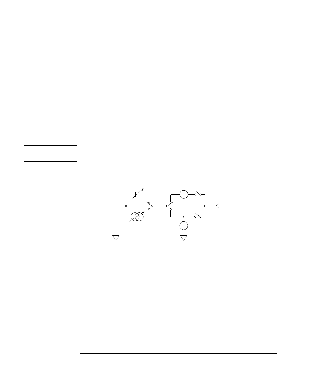
Introduction
SMU
Force
Common
V
A
+
-
+-
Measurement Resources
About SMU
Source/monitor unit (SMU) can apply DC voltage or current, and can measure DC
current or voltage. Figure 1-2 is a simplified SMU circuit diagram.
The MPSMU can perform the following operations:
• Apply voltage and measures current or voltage
• Apply current and measures current or voltage
The HCSMU, MCSMU, and HVSMU can perform the following operations:
• Apply voltage and measures current and/or voltage
• Apply current and measures current and/or voltage
NOTE To select the SMU operation mode in the GPIB remote condition, enter the CMM
command.
Figure 1-2 Simplified SMU Circuit Diagram
Compliance
The SMU has a compliance feature that limits output voltage or current to prevent
damage to the device under test. When the SMU applies voltage, you can specify
current compliance. When the SMU applies current, you can specify voltage
compliance. For details on the compliance, see Keysight EasyEXPERT User’s
Guide Vol. 1.
1- 24 Keysight B1507A User’s Guide, Ed ition 1
Page 51

MPSMU - Medium Power SMU
100 100
40
402020
100
50
20
50
20
100
Voltage (V)
Current (mA)
-
--
-
-
-
This section describes typical specification of the medium power source/monitor
unit (MPSMU).
• Maximum voltage, current, output power: ± 100 V, ± 100 mA, 2 W
• Minimum range: 0.5 V, 1 nA
• Output/measurement value and resolution: see Table 1-4 to Table 1-7.
Figure 1-3 MPSMU Output and Measurement Ranges
Introduction
Measurement Resources
Keysight B1507A User’s Guide, Edition 1 1- 25
Page 52

Introduction
Measurement Resources
Table 1-4 MPSMU Output Voltage Ranges and Resolutions
Range Output Value
0.5 V 0 |V| 0.5 V 25 V ± 100 mA
2 V 0 |V| 2 V 100 V ± 100 mA
5 V 0 |V| 5 V 250 V ± 100 mA
20 V 0 |V| 20 V 1 mV ± 100 mA
40 V 0 |V| 20 V 2 mV ± 100 mA
20 V < |V| 40 V 2 mV ± 50 mA
100 V 0 |V| 20 V 5 mV ± 100 mA
20 V < |V| 40 V 5 mV ± 50 mA
40 V < |V| 100 V 5 mV ± 20 mA
Table 1-5 MPSMU Output Current Ranges and Resolutions
Range Output Value
1 nA 0 |I| 1.15 nA 50 fA ± 100 V
10 nA 0 |I| 11.5 nA 500 fA ± 100 V
Setting
Resolution
Setting
Resolution
Maximum
Current
Maximum
Voltage
100 nA 0 |I| 115 nA 5 pA ± 100 V
1 A0 |I| 1.15 A 50 pA ± 100 V
10 A0 |I| 11.5 A 500 pA ± 100 V
100 A0 |I| 115 A 5 nA ± 100 V
1 mA 0
10 mA 0 |I| 11.5 mA 500 nA ± 100 V
100 mA 0 |I| 20 mA 5 A ± 100 V
1- 26 Keysight B1507A User’s Guide, Ed ition 1
|I| 1.15 mA 50 nA ± 100 V
20 mA < |I| 50 mA 5 A± 40 V
50 mA < |I| 100 mA 5 A± 20 V
Page 53

Measurement Resources
Table 1-6 MPS MU Measurement Voltage Values and Resolutions
Introduction
Measurement Resolutions
Range
Measurement
a
Value
High Speed ADC High Resolution ADC
0.5 V 0 |V| 0.55 V 25 V0.5 V
2 V 0 |V| 2.2 V 100 V2 V
5 V 0 |V| 5.5 V 250 V5 V
20 V 0 |V| 22 V 1 mV 20 V
40 V 0 |V| 44 V 2 mV 40 V
100 V 0 |V| 100 V 5 mV 100 V
Table 1-7 MPS MU Measurement Current Values and Resolutions
Measurement Resolutions
Range
Measurement
a
Value
High Speed ADC High Resolution ADC
1 nA 0 |I| 1.15 nA 50 fA 10 fA
10 nA 0 |I| 11.5 nA 500 fA 10 fA
100 nA 0 |I| 115 nA 5 pA 100 fA
1 A0 |I| 1.15 A 50 pA 1 pA
10 A0 |I| 11.5 A 500 pA 10 pA
100 A0 |I| 115 A 5 nA 100 pA
1 mA 0 |I| 1.15 mA 50 nA 1 nA
10 mA 0 |I| 11.5 mA 500 nA 10 nA
100 mA 0 |I| 100 mA 5 A 100 nA
a. This column is applied to the auto ranging or the limited auto ranging.
For fixed ranging, maximum measuremen t value is Range column value.
Keysight B1507A User’s Guide, Edition 1 1- 27
Page 54
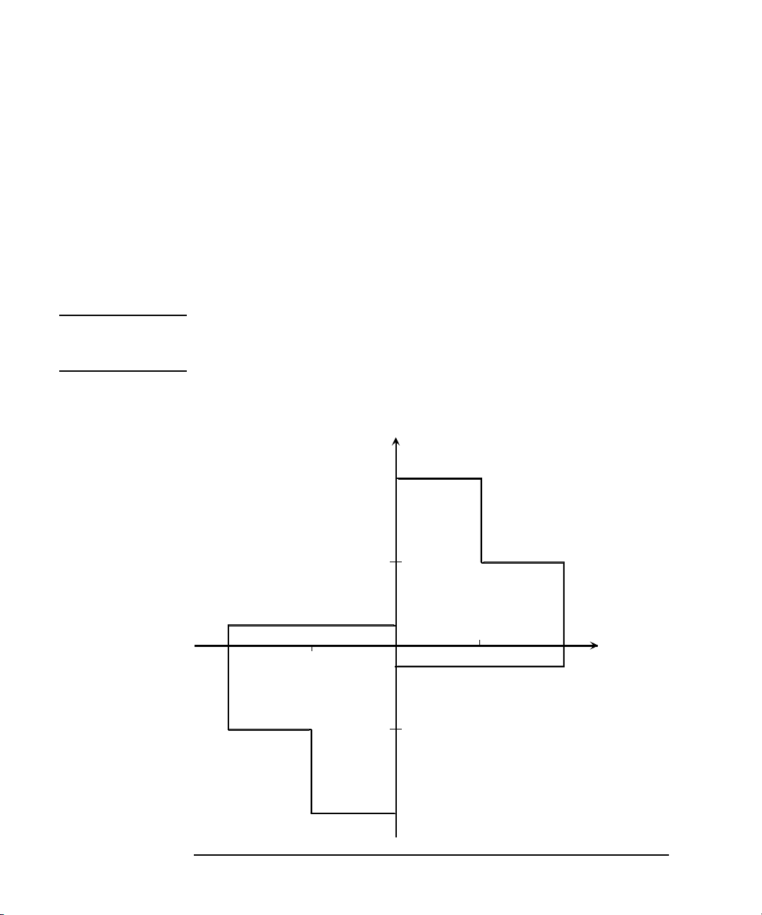
Introduction
3000
3000
1500
1500
8
4
4
8
Voltage (V)
Current (mA)
-
-
-
-
1
-
1
Measurement Resources
HVSMU - High Voltage SMU
This section describes typical specification of the high voltage source/monitor unit
(HVSMU).
• Maximum voltage/current: 3000 V/4 mA, -3000 V/-4 mA, 1500 V/8 mA, or
-1500 V/-8 mA
• Maximum output power: 12 W
• Minimum range: 200 V, 1 nA
• Output/measurement value and resolution: see Table 1-8 and Table 1-9.
CAUTION Never connect the HVSMU Force and Guard terminals to any output, including
circuit common, chassis ground, or any other measurement resource such as SMU.
Connecting other measurement resource may damage the connected one.
Figure 1-4 HVSMU Output and Measurement Ranges
1- 28 Keysight B1507A User’s Guide, Ed ition 1
Page 55

Table 1-8 HVSMU Voltage Ranges and Resolutions
Introduction
Measurement Resources
Range
Output Value and
Measurement Value
Measurement
Resolution
200 V 0 |V| 200 V 200 V8 mA
500 V 0 |V| 500 V 500 V8 mA
1500 V 0 |V| 1500 V 1.5 mV 8 mA
3000 V 0 |V| 3000 V 3 mV 4 mA
Table 1-9 H VSMU Current Ranges and Resol u t i o n s
Range
1 nA
a
Output Value and
Measurement Value
Measurement
Resolution
0 |I| 1.15 nA 10 fA 3000 V
10 nA 0 |I| 11.5 nA 100 fA 3000 V
100 nA 0 |I| 115 nA 100 fA 3000 V
1 A0 |I| 1.15 A 1 pA 3000 V
10 A0 |I| 11.5 A 10 pA 3000 V
Setting/
Setting/
Maximum Current
|Imax|
Maximum Voltage
|Vmax|
100 A0 |I| 115 A 100 pA 3000 V
1 mA 0 |I| 1.15 mA 1 nA 3000 V
10 mA 0 |I| 8 mA 10 nA 1500 V
0 |I| 4 mA 3000 V
a. DC only
Keysight B1507A User’s Guide, Edition 1 1- 29
Page 56

Introduction
Measurement Resources
MFCMU - Multi Frequency CMU
This section describes typical specification of the multi frequency capacitance
measurement unit (CMU). The CMU performs the impedance measurement and
returns the specified measurement data such as Cp-G.
• Measurement parameters: See Table 1-10.
• AC signal, output frequency:
1 kHz to 5 MHz
Setting resolution: 1 mHz (1 kHz to), 10 mHz (10 kHz to ), 0. 1 H z (100 kHz to ),
or 1 Hz (1 MHz to 5 MHz)
• AC signal, output level:
10 mVrms to 250 mVrms, 1 mV resolution
•DC bias:
0 to ± 25 V, using MFCMU internal DC bias
0 to ± 3000 V, using HVSMU and high voltage bias-tee
• Measurement range:
For the fixed ranging mode, measurement range (impedance range) must be
specified to perform measurement. Table 1-11 shows the available measurem ent
ranges and the corresponding impedance value. And Figure 1-5 shows the
calculation example of the impedance vs frequency characteristics of a
capacitive load. Use these information to decide the measurement range.
Impedance Z is calculated by the following formula.
Z = 1 / (2 f C)
where f is frequency (Hz) and C is capacitance (F).
1- 30 Keysight B1507A User’s Guide, Ed ition 1
Page 57

Table 1-10 Measurement Parameters
Primary Parameter Secondary Parameter
R (resistance, ) X (reactance, )
G (conductance, S) B (susceptance, S)
Z (impedance, ) (phase, radian)
Z (impedance, ) (phase, degree)
Y (admittance, S) (phase, radian)
Y (admittance, S) (phase, degree)
Cp (parallel capacitance, F) G (conductance, S)
Cp (parallel capacitance, F) D (dissipation factor)
Cp (parallel capacitance, F) Q (quality factor)
Cp (parallel capacitance, F) Rp (parallel resistance, )
Introduction
Measurement Resources
Cs (series capacitance, F) Rs (series resistance, )
Cs (series capacitance, F) D (dissipation factor)
Cs (series capacitance, F) Q (quality factor)
Lp (parallel inductance, H) G (conductance, S)
Lp (parallel inductance, H) D (dissipation factor)
Lp (parallel inductance, H) Q (quality factor)
Lp (parallel inductance, H) Rp (parallel resistance, )
Ls (series inductance, H) Rs (series resistance, )
Ls (series inductance, H) D (dissipation factor)
Ls (series inductance, H) Q (quality factor)
Keysight B1507A User’s Guide, Edition 1 1- 31
Page 58

Introduction
10 n7
100 n7
1 M7
10 M7
100 M7
1 m7
10 m7
100 m7
1 7
10 7
100 7
1 k7
10 k7
100 k7
1 M7
10 M7
100 M7
1 G7
10 G7
100 G7
1 T7
10 T7
1 kHz 10 kHz 100 kHz 1 MHz 5 MHz
Frequency f
Impe dance Z
10 MF
100 MF
1 mF
10 mF
100 mF
1 F
10 pF
100 pF
1 nF
10 nF
100 nF
1 MF
100 fF
1 pF
10 fF
100 aF
1 fF
300 k7 range
50 7 range
3 k7
range
Measurement Resources
Table 1-11 Measurement Range for Fixed Ranging Mode
Impedance Z
Measurement range (impedance range)
1 kHz f 200 kHz 200 kHz < f 2 MHz 2 MHz < f 5 MHz
0 Z < 100 50 50 50
100 Z < 300 100 100 100
300 Z < 1 k 300 300 300
1 k Z < 3 k 1 k 1 k 1 k
3 k Z < 10 k 3 k 3 k 3 k
10 k Z < 30 k 10 k 10 k
30 k Z < 100 k 30 k 30 k
100 k Z < 300 k 100 k
Z 300 k
300 k
Figure 1-5 Impedance vs Frequency Characteristics of Capacitive Load, Calculation
Example
1- 32 Keysight B1507A User’s Guide, Ed ition 1
Page 59

2 Installation
Page 60

Installation
This chapter describes how to install Keysight B1507A.
• “Requirements”
• “Inspection and Installation”
• “Connecting Accessories”
• “Maintenance”
• “Before Shipping to Service Center”
WARNING To avoid electrical shock and instrument damage, turn the all instruments off
before connecting or disconnecting measurement cable.
Mettez la machine hors tension pour fixer le connecteur ou pour retirer le
connecteur de l’unité centrale.
WARNING The mainframe and the test fixture are heavy and require a two person lift.
Le châssis principale et l'équipement de test sont lourds et nécessitent un levage
par deux personnes.
CAUTION Do not grab the fixture cover when lifting the test fixture.
2- 2 Keysight B1507A User’s Guide, Ed ition 1
Page 61

Installation
WARNING There are potentially hazardous voltages (± 3000 Vdc for HVSMU and ± 100
Vdc for MPSMU) present at the Force, Guard, and Sense terminals of the
instruments. To prevent electrical shock, the following safety precautions must
be observed during the use of instruments.
• Connect the instrument to an electrical ground (safety ground) by using
three-conductor AC power cable.
• Connect the mainframe Interlock terminal to the selector Interlock
terminal by using an interlock cable. Also connect the selector Interlock
terminal to the test fixture Interlock terminal by using an interlock cable.
• Confirm periodically that the interlock function works normally.
• Before touching the connections on the Force, Guard, and Sense terminals
in the test fixture or the shielding box, turn the instruments off and
discharge any capacitors. If you do not turn the instruments off, complete
all of the following items, regardless of the instrument settings.
• Press the front panel
Stop
key to set the source output off.
• Confirm that the front panel High Voltage indicator is not lit.
• Open the Interlock terminal (open the fixture cover or the shielding box
access door).
• Discharge any capacitors connected to a measurement resource.
• Warn persons working around the instruments about dangerous
conditions.
Keysight B1507A User’s Guide, Edition 1 2- 3
Page 62

Installation
Requirements
Requirements
This section describes the requirements for the environment this instrument is used.
• “Power Requirements”
• “Operating Environment”
• “Storaging/Shipping Environment”
• “Installation Requirements”
• “Power Cable”
Power Requirements
This instrument can operate fr om any singl e-phase AC pow er source supp lying 100/
240 V (±10 %) at 50/60 Hz. The maximum power consumption is shown below.
• Mainframe: 900 VA
• Selector: 70 VA
Operating Envir onment
This instrument must be operated within the following environmental conditions:
Temperature: +5 C to +40 C
Humidity: 20 % to 70 % RH, no condensation
Altitude: 0 to 2,000 m (6,561 ft.)
Storaging/Shipping Environment
This instrument must be stored/shipped within the following environmental
conditions:
Temperature: -20 C to +60 C
Humidity: 10 % to 90 % RH, no condensation
Altitude: 0 to 4,600 m (15,092 ft.)
2- 4 Keysight B1507A User’s Guide, Ed ition 1
Page 63

Installation
Requirements
Installation Requirements
WARNING Do not operate the instrument in dusty environment, or in the presence of
flammable gasses, corrosive gasses, or fumes.
Ne pas utiliser l’appareil dans un endroit poussiéreux, ou en présence de gaz
inflammables, corrosifs ou de fumée.
• Environmental conditions for this instrument are documented in the previous
page. In principle, this instrument should only be operated indoors in a
controlled environment.
• Install the instrument horizontal place then face the roof up.
• The dime nsions of thi s instrumen t are shown below. Fan cools the instrument by
drawing air through the sides and exhausting it out the back. The instrument
must be installed in a location that allows sufficient space at the sides and back
of the instrument for adequate air circulation.
• Mainframe: 420 mm (W) 575 mm (D) 330 mm (H)
• Selector: 420 mm (W) 575 mm (D) 75 mm (H)
• Test fixture: 340 mm (W) 345 mm (D) 200 mm (H)
If the airflow is restricted, the internal operating temperature will be higher. This
may reduce the instrument’s reliability, or cause the thermal-protection circuits
to turn the instrument off.
• Make sure that there is enough space for connecting/disconnecting the power
cable easily.
Keysight B1507A User’s Guide, Edition 1 2- 5
Page 64

Installation
Requirements
Power Cable
WARNING FIRE HAZARD: Use only the power cable supplied with your instrument.
Using other types of power cable may cause overheating of the power cable,
resulting in fire.
SHOCK HAZARD: The power cable provides the chassis ground through a
third conductor. Be sure to connect to a three-conductor type power outlet with
the correct pin grounded.
RISQUE D’INCENDIE : utilisez uniquement le câble d'alimentation fourni
avec votre appareil. L’utilisation d’autres types de câble d’alimentation peut
provoquer une surchauffe du câble d’alimentation et provoquer un incendie.
RISQUE DE CHOC ÉLECTRIQUE: le câble d’alimentation fournit la masse
du châssis par le biais d’un troisième conducteur. Assurez-vous de connecter la
prise d'alimentation de type trois conducteurs av ec la broche correcte mise à la
terre.
NOTE The detachable power cable may be used as an emergency disconnecting device.
Removing the power cable will disconnect AC input power to the instrument.
Connect the power cable to the IEC 320 connector on the rear of the instrument. If
the wrong power cable was shipped with your instrument, contact your nearest
Keysight Sales and Support Office.
The AC input on the back of your instrument is a universal AC input. It accepts
nominal line voltages in the range of 100 to 240 VAC.
2- 6 Keysight B1507A User’s Guide, Ed ition 1
Page 65

Installation
Requirements
Option 900
• Plug: BS 1363/A,
250 V, 10 A
• PN: 8120-4420
Option 904
• Plug: NEMA 6-15P,
250 V, 10 A
• PN: 8120-3996
Option 918
• Plug: JIS C 8303,
125 V, 12 A
• PN: 8121-0743
Option 922
Option 901
• Plug: AS/NZS 3112,
250 V, 10 A
• PN: 8120-4419
Option 906
• Plug: SEV 1011,
250 V, 10 A
• PN: 8120-4416
Option 919
• Plug: Israel SI 32,
250 V, 10 A
• PN: 8121-0724
Option 923
Option 902
• Plug: IEC 60277-1,
250 V, 10 A
• PN: 8121-1226
Option 912
• Plug: SB 107-2-D1,
250 V, 10 A
• PN: 8121-1655
Option 920
• Plug: IRAM 2073,
250 V, 10 A
• PN: 8121-0725
Option 927
Option 903
• Plug: NEMA 5-15P,
125 V, 10 A
• PN: 8120-6825
Option 917
• Plug: IS 1293 and
IS 6538, 250 V, 10 A
• PN: 8121-1690
Option 921
• Plug: CEI 23-16,
250 V, 10 A
• PN: 8121-0722
Option 930
• Plug: GB 1002
figure 3, 250 V, 10 A
• PN: 8120-8376
Option 931
• Plug: CNS 10917-2,
125 V, 10 A
• PN: 8121-1635
• Plug: SANS 164-1,
250 V, 10 A
• PN: 8121-0564
Option 932
• Plug: CS 0017,
250 V, 10 A
• PN: 8121-1638
• Plug: NEMA WD-6,
250 V, 10 A
• PN: 8120-0674
• Plug: NBR 14136,
250 V, 10 A
• PN: 8121-1809
Keysight B1507A User’s Guide, Edition 1 2- 7
Page 66

Installation
Inspection and Installation
Inspection and Installation
Do the following when this instrument arrived.
• “To Inspect Shipment”
• “To Perform Initial Setup”
• “To Connect Selector and Test Fixture”
• “To Check Operation of Selector”
Do the following setup if you need.
• “To Change Windows Logon Setting”
• “To Change GPIB Address”
• “To Enable System Controller”
To Inspect Shipment
1. Before unpacking any components, inspect all boxes for any signs of damage
that might have occurred during shipment, such as:
•dents
• scratches
•cuts
• water marks
If you suspect any damage, contact Keysight Technologies.
2. When you open the boxes that contain the instrument and accessories, check the
components against the contents lists attached to the boxes.
If anything is missing, contact Keysight Technologies.
After the inspection, move the instrument and acces sories to the installation site. For
the requirements for the installation site, see “Requirements” on page 2-4.
2- 8 Keysight B1507A User’s Guide, Ed ition 1
Page 67

Installation
Inspection and Installation
To Perform Initial Setup
1. Place the mainframe at the installation site.
2. Make sure that the Standby switch is set to off.
3. On the rear panel, connect the Circuit Common terminal to the frame ground
terminal by using a shorting-bar.
4. If you use the furnished USB keyboard and/o r USB mouse, connect it to an USB
port of the mainframe.
5. Connect the power cable from the mainframe to an AC power outlet.
6. Open the measurement terminals and press the Standby switc h to turn on the
mainframe.
If the mainframe is operating correctly, the power-on self-test is automatically
performed. If problems arise, contact Keysight Technologies.
7. Follow the Windows setup wizard and complete the initial setup.
a. Set the system display language to Englis h. The language must be English. If
you set another language, you must perform the system recovery of the
B1507A. See Keysight EasyEXPERT User’s Guide Vol. 2 for the system
recovery.
b. Set Country or region, Time and currency, and Keyboard layout.
If you use the furnished USB keyboard, the Keyboard layout must be US.
c. Accept the End User License Agreement.
d. Set Time zone, date and time.
If the mainframe has been already connected to y our site LAN, you can p roceed the
network connection setup. If y ou conn ect the mainfr ame to the n etwork, take care to
protect it from computer virus.
NOTE
NOTE Keysight T echnologies cannot guarantee the performance and provide compatibility
Other Windows setup
You can set other setup of Windows after the initial setup. It is your responsibility.
information for all B1507As under several conditions. If problems arise, perform
Keysight B1507A system recover y.
To perform recovery, see Keysight EasyEXPERT User’s Guide Vol. 2.
Keysight B1507A User’s Guide, Edition 1 2- 9
Page 68

Installation
Inspection and Installation
Users listed in Table 2-1 are available just after the initial setup.
Table 2-1 Users Available Just After the Initial Setup
User Account Description
Keysight B1500
User
keysightOnly Account for Keysight service personnel. Do not delete
Administrator Administrator. Password is not set to this account.
You can add users after the initial setup. Add users as you need.
Account for automatic logon. Password is not set to this
account.
this account. This account is password protected.
2- 10 Keysight B1507A User’s Guide, Ed ition 1
Page 69
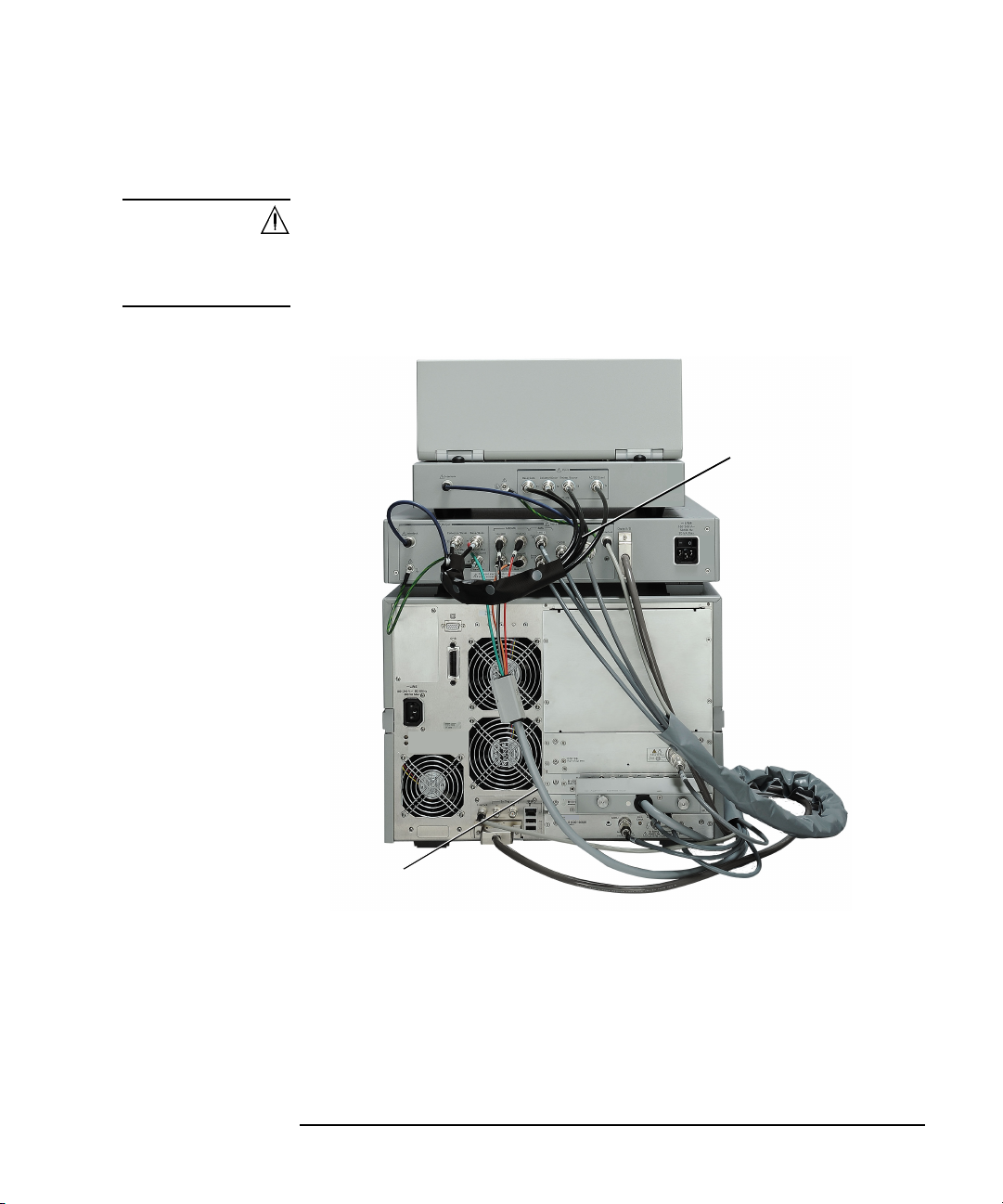
Installation
System cable 1
CMU cable
Digital I/O cable
System cable 2
Selector
Test fixture
Mainframe
Inspection and Installation
To Connect Selector and Test Fixture
WARNING To avoid electrical shock and instrument damage, turn the all instruments off
before connecting or disconnecting measurement cable.
Mettez la machine hors tension pour fixer le connecteur ou pour retirer le
connecteur de l’unité centrale.
Figure 2-1 B1507A Rear View
Connect the system cables between the mainframe, selector, and test fixture as
shown in Figure 2-1. Also see Tables 2-2 and 2-3.
1. Connect the System cable between the mainframe and the selector.
2. Connect the CMU cable.
3. Connect the Digital I/O cable.
Keysight B1507A User’s Guide, Edition 1 2- 11
Page 70
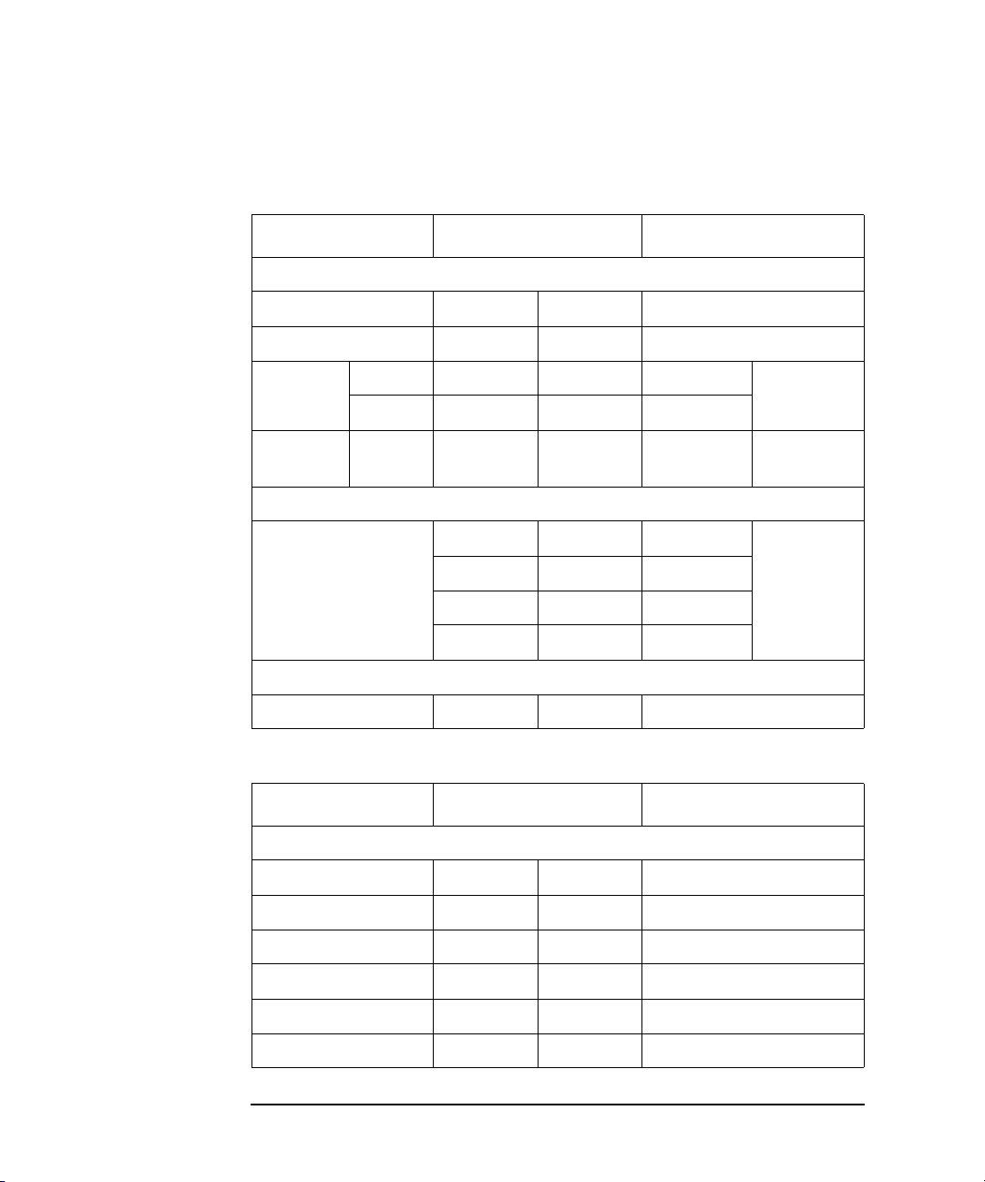
Installation
Inspection and Installation
4. Connect the System cable between the selector and the test fixture.
Table 2-2 System Cable Connections between Main frame and Sel ector
Mainframe Lab el of Cable Selector
System Cable 1
Interlock none none Interlock
GNDU GNDU GNDU GNDU
SMU1 Sense 1S 1S Sense (1S) SMU
Force 1F 1F Force (1F)
SMU2 Force 2 2 Force (2F) HVSMU
CMU Cable
MFCMU Hpot HP Hpot (HP) MFCMU
Lpot LP Lpot (LP)
SMU1
SMU2
Hcur HC Hcur (HC)
Lcur LC Lcur (LC)
Digital I/O Cable
Digital I/O none none Digital I/O
Table 2-3 System Cable Connections between Selector and T est Fixtur e
Selector Label of Cable Test Fixture
System Cable 2
AC/DC Guard T4 T4 AC/DC Guard
Emitter/Source T3 T3 Emitter/Source
Base/Gate T1 T1 Base/Gate
Collector/Drain T2 T2 Collector/Drain
Earth terminal none none Earth terminal
Interlock none none Interlock
2- 12 Keysight B1507A User’s Guide, Ed ition 1
Page 71

Installation
Inspection and Installation
To Check Operation of Selector
1. Complete the cable connections described in “To Connect Selector and Test
Fixture” on page 2-11 .
2. Connect the power cable from the selector to an AC power outlet.
3. Connect the power cable from the mainframe to an AC power outlet.
4. Open the measurement terminals of the test fixture and close the fixture cover.
5. Set the selector power switch to the ON position to turn on the selector.
6. Press the mainframe Standby switch to turn on the mainframe.
7. After boot up, launch the Capacitance Measurement software.
8. Click the Configuration > Module menu to display the Module Configuration
dialog box .
9. Perform diagnosis of the selector by using the Module Configuration dialog box.
If problems arise, contact Keysight Technologies.
To Change Windows Logon Setting
Windows automatic logon has been enabled initially. If you want to change this
setting, select All Programs > Control Auto Logon from the Start menu. Control
Auto Logon is disp l ayed on the browser. Then click one of the following but tons on
the browser and follow the setup script.
• Enable Auto Logon
• Disable Auto Logon
NOTE If you set a password for the user account Keysight B1500 User, disable the
automatic logon.
Keysight B1507A User’s Guide, Edition 1 2- 13
Page 72

Installation
Inspection and Installation
To Change GPIB Address
When this instrument is shipped from the factory, the GPIB address is set to 17. To
change the GPIB address, perform the following procedure.
1. If the EasyEXPERT software is running, terminate it as shown below:
a. Select the menu function File > Exit on the EasyEXPERT main screen.
b. Click [x] at the upper right corner of the Start EasyEXPERT button.
2. Select All Programs > Keysight IO Libraries Suite > Keysight Connection
Expert from the Start menu. Keysight Connection Expert window appears.
3. At the Instrument I/O on this PC area, select GPIB0, and click the Change
Properties... button. Keysight 82350 PCI GPIB Interface - GPIB0 window
appears.
4. Change the GPIB Address value.
5. Remove the check from the Auto-discover instruments connected to this
interface box.
6. Click the OK button on Keysight 82350 PCI GPIB Interface - GPIB0 window.
7. On the Reboot Required dialog box, click the Reboot Now button, and reboot
the mainframe.
2- 14 Keysight B1507A User’s Guide, Ed ition 1
Page 73

Installation
Inspection and Installation
To Enable System Controller
To allow this instrument to control external GPIB devices, perform the following
procedure. After the procedure, you cannot control the instrument from an external
computer.
1. If the EasyEXPERT software is running, terminate it as shown below:
a. Select the menu function File > Exit on the EasyEXPERT main screen.
b. Click [x] at the upper right corner of the Start EasyEXPERT button.
2. Select All Programs > Keysight IO Libraries Suite > Keysight Connection
Expert from the Start menu. Keysight Connection Expert window appears.
3. At the Instrument I/O on this PC area, select GPIB0, and click the Change
Properties... button. Keysight 82350 PCI GPIB Interface - GPIB0 window
appears.
4. Set the GPIB Address value to 21 that is the typical address number for the
system controller.
5. Check the System Controller box.
6. Remove the check from the Auto-discover instruments connected to this
interface box.
NOTE
This disables the automatic device detection. So the Connection Expert cannot
detect the instruments connected to the GPIB interface by itself.
7. Click the OK button on Keysight 82350 PCI GPIB Interface - GPIB0 window.
8. On the Reboot Required dialog box, click the Reboot Now button, and reboot
the mainframe.
To Disable System Controller
To disable the system controller, change the steps 4 and 5 for setting the GPIB
Address val ue to not 21 and removing the check from the System Controller box,
and perform the procedure to the step 8.
Keysight B1507A User’s Guide, Edition 1 2- 15
Page 74

Installation
Connecting Accessories
Connecting Accessories
The test fixture is used to connect your device under test (DUT). The B1507A is
furnished with the following accessories.
• “3-pin Inline Package Socket Module”
• “Accessories for Connecting a DUT”
WARNING Set the instrument output off before connecting or disconnecting connection
wire.
Press the mainframe front panel
confirm that the mainframe front panel High Voltage indicator is not lit.
WARNING To prevent electrical shock and DUT damage, do not connect or disconnect the
DUT while the instrument is applying voltage or current.
When you touch the DUT after measurement, devise a countermeasure of
residual charge and heat to prevent electrical shock and burn. Use glove and
any tool. Al so have enough time for discharge and ra diation.
Pour éviter toute électrocution et tout risque d'endommagement de l'appareil,
ne retirez pas les câbles pendant le fonctionnement.
Lorsque vous touchez le MST après la mesure, élaborez une contre-mesure de
la charge résiduelle et du chauffage afin d'éviter tout choc électrique et toute
brûlure. Utilisez des gants et des outils. Prévoyez également du temps pour la
décharge et la radiation.
Stop
key to set the source output off. And
2- 16 Keysight B1507A User’s Guide, Ed ition 1
Page 75

Connecting Accessories
Socket module
Test fixture
DUT
Chassis
common
3-pin Inline Package Socket Module
Use the socket module to connect a three-terminal inline packaged device. See the
following simple instruction.
Requirements • 3-pin inline package socket module
• DUT
Procedure 1. If the earthing wire is not connected to the socket module, connect it.
2. Attach the socket module directly to the Base/Gate, Collector/Drain, and
Emitter/Source terminals of the test fixture.
3. Connect the earthing wire of the socket module to the chassis common terminal.
4. Set your DUT on the socket.
5. Close the fixture cover and perform measurement.
Installation
WARNING Hazardous voltage, instrument maximum output voltage may appear at the
measurement terminals if the fixture cover is closed.
WARNING Open the Guard terminal of the test fixture. Do not connect anything to it.
NOTE Short plate is furnished with the socket module. It is used for performing the short
correction before the capacitance measurement. Set it on the socket before the short
correction and remove it after the correction.
Keysight B1507A User’s Guide, Edition 1 2- 17
Page 76
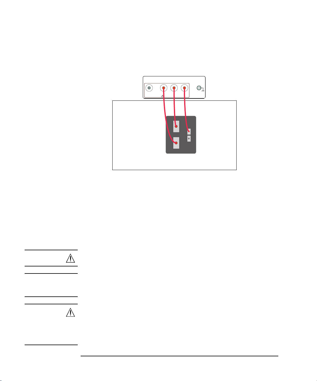
Installation
Base Low is internally
connected to Emitter.
Base
Base
Emitter
Low High
Collector
AC/DC Guard Emitter/Source Collector/Drain Base/Gate
±3 kV&Max
Connecting Accessories
Accessories for Connecting a DUT
Use the connection wire, clip, adapter, and so on to connect a device other than
3-pin inline package.
Requirements • Connection wire, clip, adapter, and so on. Use the furnished accessories.
• DUT (other than 3-pin inline package device)
Procedure 1. Put your DUT on the DUT stage (silicon plate). The device size should be
smaller than approximately 280 mm (W) 140 mm (D) 100 mm (H).
2. Connect your DUT to the measurement terminals of the test fixture by using
connection wire, clip, adapter, and so on.
3. Close the fixture cover and perform measurement.
WARNING Hazardous voltage, instrument maximum output voltage may appear at the
measurement terminals if the fixture cover is closed.
WARNING Open the AC/DC Guard terminal to avoid electrical shock, instrument
damage, or DUT damage. Do not connect anything to this terminal which may
have the same potential as the Collector/Drain terminal.
WARNING Make sure that the cover is closed properly before starting measurement. Do
not perform the measurement when a wire is protruding fr om the fi xture cover.
Assurez-vous que le couvercle est fermé correctement avant de commencer la
mesure. Ne pas effectuer la mesure lorsqu’un câble dépasse du couvercle de
l'appareil.
2- 18 Keysight B1507A User’s Guide, Ed ition 1
Page 77

Installation
Maintenance
Maintenance
Maintenance should be performed periodically to keep the instrument in good
condition.
Cleaning
Before performing cleaning, turn off the instrument, and disconnect power cable
from the rear panel. Use a dry cloth to clean the external case parts.
To prevent electrical shock, do not perform cleaning when the instrument is turned
on, and do not use a wet cloth.
Self-test and Diagnosis
This instrument provides the following functions to check the operation. Perform
the following functions as necessary. Open the measurement terminals to perform
self-test, self-calibration, or diagnosis.
NOTE
• Self-test
• Self-calibration
• Diagnosis
If problems arise, contact Keysight Technologies.
Interlock Open/Close test and High Voltage LED test
Interlock function limits the maximum output voltage to ± 42 V when the
measurement terminal is touchable. For safety , this function must be checked befor e
using the instrument after power on at least once a day by performing the diagnosis.
Calibration
Calibration and adjustments must be performed periodically so that the instruments
satisfy the specifications, and keep a good condition. It is recommended to perform
the calibration once a year at least. For the calibration and adjustments, contact
Keysight Technologies. Trained service personnel will perform the calibration and
adjustments.
Keysight B1507A User’s Guide, Edition 1 2- 19
Page 78

Installation
Before Shipping to Service Center
Before Shipping to Service Center
Before shipping this instrument to service center, you have to do following:
• “To Make Backup”
• “To Check Module Slots”
• “To Collect Equipment and Accessories”
To Make Backup
If the internal hard disk drive (HDD) is failed, you will lose all data stored in the
HDD. So it is important to make backup constantly.
Before shipping the instrument to the service center, make backup of data in the
HDD. And keep the backup media in trust. You may need to perform data recovery
of the instrument returned from the service center.
If the HDD is replaced, the instrument will be returned with the latest revision of th e
software.
To Check Module Slots
Do not remove the plug-in module from the mainframe. The instrument must be
shipped with all modules. The module cannot be repaired or calibrated wi thout the
mainframe.
If a module is removed and installed, the specifications are not guaranteed. The
specifications are guaranteed after the calibration is performed at Keysight
Technologies service center.
To Collect Equipment and Accessories
The mainframe, test fixture, and all connection cables are required for serv icing and
must be shipped to the service center. For details, contact the service center.
WARNING To prevent electrical shock, turn off the instrument and remove the power
cable before removing the connection cables.
Mettez la machine hors tension pour fixer le connecteur ou pour retirer le
connecteur de l’unité centrale.
2- 20 Keysight B1507A User’s Guide, Ed ition 1
Page 79

3 How To Perform Measurement
Page 80

How To Perform Measurement
This chapter describes how to measure the power devices by using Keysight
B1507A and Keysight Easy Test Navigator Software, and consists of th e following
sections:
• How To Perform Capacitance Measurement
This section describes how to perform the measurement using the capacitance
measurement software.
• How To Perform I/V Measurement
This section describes how to perform the measurement using the I/V
measurement software.
• How To Calculate Power Loss
This section describes how to calculate the power loss using the power loss
calculation software.
3- 2 Keysight B1507A User’s Guide, Ed ition 1
Page 81
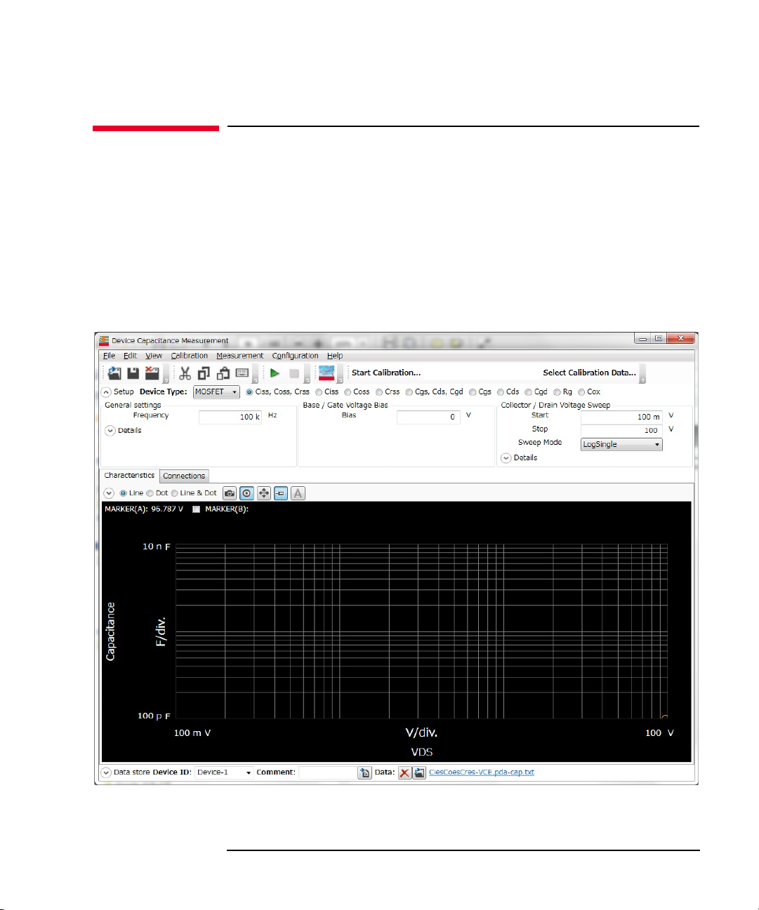
How To Perform Capacitance Measurement
How To Perform Capacitance Measurement
This section describes how to perform a measurement using the capacitance
measurement software and consists of the following sub-sections:
• Preparing Measurement
• Executing Measurement
• Setting Parameter
Figure 3-1 Capacitance Measurement Software
How To Perform Measurement
Keysight B1507A User’s Guide, Edition 1 3- 3
Page 82

How To Perform Measurement
How To Perform Capacitance Measurement
Preparing Measurement
WARNING Set the instrument output off before connecting or disconnecting connection
wire.
Press the mainframe front panel Stop key to set the source output off. And
confirm that the mainframe front panel High Voltage indicator is not lit.
WARNING To prevent electrical shock and DUT damage, do not connect or disconnect the
DUT while the instrument is applying voltage or current.
When you touch the DUT after measurement, devise a countermeasure of
residual charge and heat to prevent electrical shock and burn. Use glove and
any tool. Al so have enough time for discharge and ra diation.
Step 1. Prepare the test fixture and other accessories to connect your device under test
(DUT).
For more information on the test fixture and its accessories, see the following
sections:
• “To Connect Selector and Test Fixture” on page 2-11
• “3-pin Inline Package Socket Module” on page 2-17
• “Accessories for Connecting a DUT” on page 2-18
Step 2. Connect the test fixture and, 3-pin inline package socket module or other accessories
that is adequate for your DUT.
For more information, see the following sections:
• “To Connect Selector and Test Fixture” on page 2-11
• “3-pin Inline Package Socket Module” on page 2-17
• “Accessories for Connecting a DUT” on page 2-18
Step 3. Turn the instrument on.
Don’t connect your DUT to the test fixture at this time.
3- 4 Keysight B1507A User’s Guide, Ed ition 1
Page 83

How To Perform Measurement
How To Perform Capacitance Measurement
Executing Measuremen t
NOTE This section explains the procedure using an example that selects MOSFET as a
device type of DUT and Ciss, Coss, Crss as a measurement item.
Execute a measurement as follows:
Step 1. On the software palette, click the Capacitance Measurement icon . The
Capacitance Measurement software (Figure 3-1) opens.
Step 2. At the Setup area in work area, select a device type of your DUT and a measurement
item to be measured.
• Device Type
Select a device type from the Device Type drop-down list.
NOTE This example selects MOSFET.
• Measurement Item
From the radio buttons located on the right of a Device Type selection, which is
MOSFET in this example, select a measurement item to be measured.
NOTE This example selects Ciss, Coss, Crss.
NOTE For information on the available device types and measurement items, see T able 3-1
on page 3-8
By selecting a device type and measurement item, the setup items displayed in
the Setup area are automatically switched.
Keysight B1507A User’s Guide, Edition 1 3- 5
Page 84
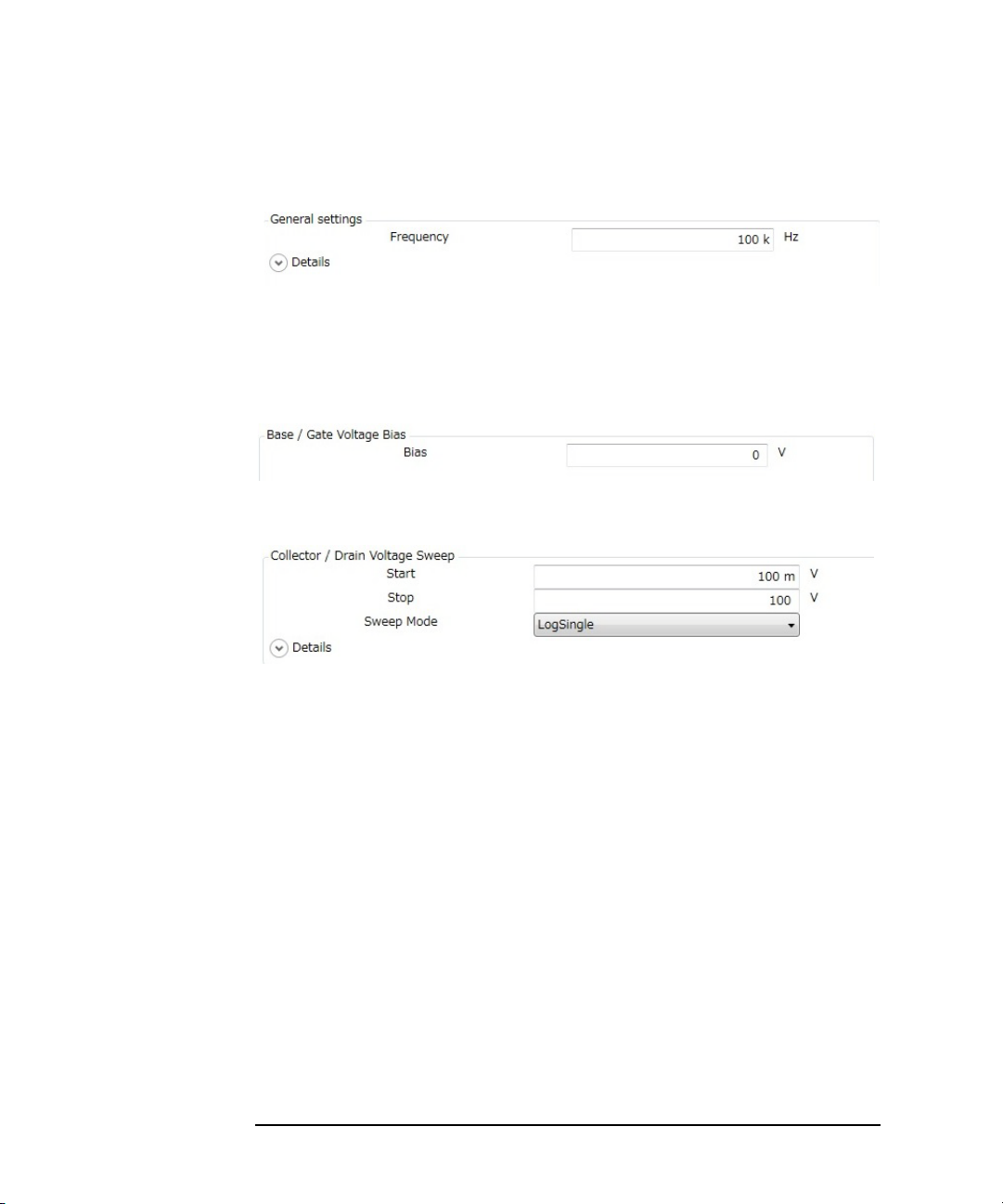
How To Perform Measurement
How To Perform Capacitance Measurement
Step 3. Enter the measurement frequency in the Frequency of General settings located at th e
left part of Setup area.
By clicking the
Details
chevron, the area expands to set more detail conditions.
For more information on setting items, see “Setup” on page 4-11.
Step 4. Enter the bias voltage value in the Bias of Base/Gate Voltage Bias at the center of
Setup area.
Step 5. Enter or select the voltage sweep conditions in the Collector/Drain Voltage Sweep at
the right of Setup area.
Start Enter a start voltage value of sweep.
Stop Enter a stop voltage value of sweep.
Sweep Mode Select a sweep mode.
LinearSingle One-way linear sweep from the Start to the
Stop.
LogSingle One-way logarithmic sweep from the Start
to the Stop.
LinearDouble Linear-sweep from the Start to the Stop and
then return linear-sweep from the Stop to
the Start.
LogDouble Logarithmic-sweep from the Start to the
Stop and then return logarithmic-sweep
from the Stop to the Start.
By clicking the
Details
chevron, the area expands to set more detail conditions.
3- 6 Keysight B1507A User’s Guide, Ed ition 1
Page 85

How To Perform Measurement
How To Perform Capacitance Measurement
For more information on setting items, see “Setup” on page 4-11.
Step 6. Click the Start Calibration... button in the toolbar to measure the calibration data of
measurement path.
Follow the instruction displayed on the dialog to measure the open and short
calibration data.
If you have measured and saved the calibration data of measurement path, click the
Select Calibration Data... button in the toolbar to select and load the stored
calibration data.
Step 7. Set your DUT on the test fixture and click the Start Measurement button to
start a measurement.
You can stop the measurement by clicking the Stop Measurement button
during a measurement execution.
NOTE If your DUT is diode, connect the cathode of your DUT to the Collector/Drain
terminal of the test fixture and the anode of your DUT to the Emitter/Source
terminal of the test fixture.
Step 8. Click the Ch aracteristics tab to display the Characteristics area.
After a measurement is finished, a measured capacitance characteristics curve is
displayed on the Characteristics area. This example shows the Ciss, Coss, and Crss,
characteristics curves.
Keysight B1507A User’s Guide, Edition 1 3- 7
Page 86

How To Perform Measurement
How To Perform Capacitance Measurement
For the operation on the graph display, see “Displaying and Operating Graph” on
page 3-26.
Setting Parameters
Table 3-1 Available Device Types and Measurement Items
Device Type
MOSFET Ciss
IGBT Cies
Diode CT Total capacitance at reverse bias to bias voltage
Generic Collector/Drain
Measurement
Item
Coss
Crss
Ciss, Coss, Crss
Cgs
Cds
Cgd
Cgs, Cds, Cgd
Rg
Cox
Coes
Cres
Cies, Coes, Cres
Cge
Cce
Cgc
Cge, Cce, Cgc
Rg
Voltage Sweep
Base/Gate
Voltage Sweep
Description
Ciss (Input capacitance) - Vds characteristics
Coss (Output capacitance) - Vds characteristics
Crss (Feedback capacitance) - Vds characteristics
Ciss, Coss, and Crss characteristics
Cgs (Gate to Source capacitance) - Vds characteristics
Cds (Drain to Source capacitance) - Vds characteristics
Cgd (Gate to Drain capacitance) - Vds characteristics
Cgs, Cds, and Cgd characteristics
Rg (Gate resistance) - Vgs characteristics
Cox (Gate oxide film capacitance) - Vgs characteristics
Cies (Input capacitance) - Vce characteristics
Coes (Output capacitance) - Vce characteristics
Cres (Feedback capacitance) - Vce characteristics
Cies, Coes, and Cres characteristics
Cge (Gate to Emitter capacitance) - Vce characteristics
Cce (Collector to Emitter capacitance) - Vce characteristics
Cgc (Gate to Collector capacitance) - Vce characteristics
Cge, Cce, and Cgc characteristics
Rg (Gate resistance) - Vge characteristics
characteristics
Cp-G model capacitance between Collector/Drain terminal
and Emitter/Source terminal to Vce/Vds characteristics
Cs-Rs model capacitance between Base/Gate terminal and
Emitter/Source terminal to Vbe/Vgs characteristics
3- 8 Keysight B1507A User’s Guide, Ed ition 1
Page 87

How To Perform I/V Measurement
This section describes how to perform a measurement using the I/V measurement
software and consists of the following sub-sections:
• Preparing Measurement
• Executing Measurement
• Setting Parameter
Figure 3-2 I/V Measurement Software
How To Perform Measurement
How To Perform I/V Measurement
Keysight B1507A User’s Guide, Edition 1 3- 9
Page 88

How To Perform Measurement
How To Perform I/V Measurement
Preparing Measurement
WARNING Set the instrument output off before connecting or disconnecting connection
wire.
Press the mainframe front panel Stop key to set the source output off. And
confirm that the mainframe front panel High Voltage indicator is not lit.
WARNING To prevent electrical shock and DUT damage, do not connect or disconnect the
DUT while the instrument is applying voltage or current.
When you touch the DUT after measurement, devise a countermeasure of
residual charge and heat to prevent electrical shock and burn. Use glove and
any tool. Al so have enough time for discharge and ra diation.
Step 1. Prepare the test fixture and other accessories to connect your device under test
(DUT).
For more information on the test fixture and its accessories, see the following
sections:
• “To Connect Selector and Test Fixture” on page 2-11
• “3-pin Inline Package Socket Module” on page 2-17
• “Accessories for Connecting a DUT” on page 2-18
Step 2. Connect the test fixture and, 3-pin inline package socket module or other accessories
that is adequate for your DUT.
For more information, see the following sections:
• “To Connect Selector and Test Fixture” on page 2-11
• “3-pin Inline Package Socket Module” on page 2-17
• “Accessories for Connecting a DUT” on page 2-18
Step 3. Turn the instrument on and then connect your DUT to the test fixture.
If your DUT is diode, connect a cathode terminal of your DUT to the
Collector/Drain terminal of test fixture and a anode terminal of your DUT to the
Emitter/Source terminal of test fixture.
3- 10 Keysight B1507A User’s Guide, Ed ition 1
Page 89

How To Perform Measurement
How To Perform I/V Measurement
Executing Measuremen t
NOTE This section explains the procedure using an example that selects MOSFET as a
device type of DUT and ID-VDS as a measurement item.
Execute a measurement as follows:
Step 1. On the software palette, click the I/V Measurement icon . The I/V Measurement
software (Figure 3-2) opens.
Step 2. At the Setup area in work area, select a device type and measurement item to be
measured.
• Device Type
From the Device Type drop-down list, select a device type.
NOTE This example selects MOSFET.
• Measurement Item
From the radio buttons located on the right of a Device Type selection, which is
MOSFET in this example, select a measurement item to be measured.
NOTE This example selects ID-VDS.
NOTE For information on the available device types and measurement items, see T able 3-2
on page 3-17
By selecting a device type and measurement item, the setup items displayed in the
Setup area are automatically switched.
Keysight B1507A User’s Guide, Edition 1 3- 11
Page 90

How To Perform Measurement
How To Perform I/V Measurement
Step 3. Enter or select the setup conditions for the gate of MOSFET in Gate/Base Voltage
Pulse Step at the center of Setup area.
• Selecting Step Mode
From the Step Mode drop-down list, select a step mode of pulse voltage output.
LinearSingle Outputs voltage level changes from the Start value to the
Stop value at equal intervals.
ListSingle Specify the output voltages of each step in the List.
Each step voltage in the List will be output in order from top
to bottom.
NOTE This example selects the ListSingle.
• To change step values
Click the value in the List and you can change it to new value.
• To insert new step value
3- 12 Keysight B1507A User’s Guide, Ed ition 1
Page 91
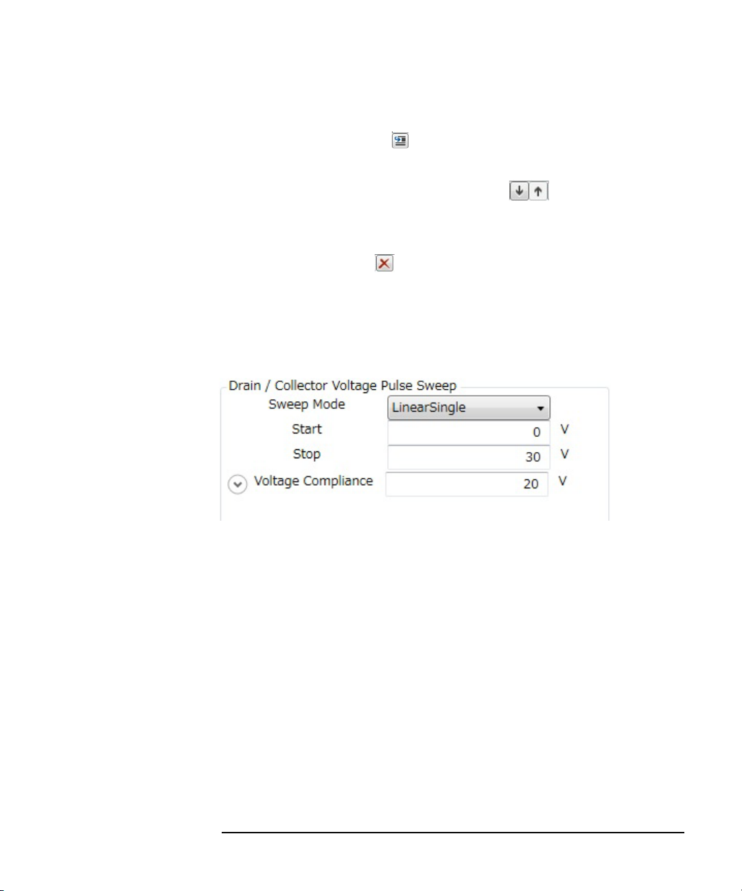
How To Perform Measurement
How To Perform I/V Measurement
Select the step value immediately after where you want to insert new step value
and click the Insert button .
• To change an output order of step values
Click the Move Down and the Move Up buttons to move down or up an
order of the selected step value.
• To delete a step value
Click the Delete button to delete the selected step value.
By clicking the
Details
chevron, the area expands to set more detail conditions.
For more information on setting items, see “Setup” on page 4-38.
Step 4. Enter or select the setup conditions for the drain of MOSFET in Drain/Collecto r
Voltage Pulse Sweep at the right side of Setup area.
Select or specify a sweep mode, a sweep start value, a sweep stop value, and a
voltage compliance.
• Sweep Mode
Select a sweep mode from the Sweep Mode drop-down list.
LinearSingle One-way linear sweep from the Start (sweep start value) to
the Stop (sweep stop value).
LogSingle One-way logarithmic sweep from the Start (sweep start
value) to the Stop (sweep stop value).
LinearDouble Linear-sweep from the Start (sweep start value) to the Stop
(sweep stop value) and then return linear-sweep from the
Stop to the Start.
Keysight B1507A User’s Guide, Edition 1 3- 13
Page 92

How To Perform Measurement
How To Perform I/V Measurement
LogDouble Logarithmic-sweep from the Star t (sweep start v alue) to the
Stop (sweep stop value) and then return logarithmic-sweep
from the Stop to the Start。
•Start、Stop
Enter the sweep start value in the Start and the sweep stop value in the Stop.
• Vo ltage Compliance
Enter the voltage compliance value in the Voltage Compliance.
If the output voltage of measurement unit connected to a drain terminal is more
than this value, a measurement unit stops the output.
By clicking the
Details
chevron, the area expands to set more detail conditions.
For more information on setting items, see “Setup” on page 4-38.
Step 5. Enter the setup conditions for the pulse output in General settings at the left side of
Setup area.
Auto Period Automatic adjustment for the pulse period.
To enable this function, mark the check box.
Pulse Period Pulse period.
However, if the Au to Period function is enabled, the pulse
period is automatically adjusted to a minimum period
corresponding to the pulse width.
3- 14 Keysight B1507A User’s Guide, Ed ition 1
Page 93

How To Perform Measurement
How To Perform I/V Measurement
Step 6. Click the Connections tab to display Connections area.
At Connections area, you can confirm a measurement circuit.
Also, you can select a gate resistor/drain resistor that may be effective to suppress a
device oscillation during measurement.
• Base/Gate Resistor
You can select a gate resistor from this drop-down list.
A gate resistor may be effective to suppress a device oscillation during large
current measurement.
NOTE You can select a gate resistor only if a measurement resource is MCSMU.
In this example, which selects MOSFET as a device type and ID-VDS as a
measurement item, the default measurement res ource is MCSMU and you can select
a gate resistor.
• Collector/Drain Resistor
You can select a drain resistor from this drop-down list.
A drain resistor may be ef fective to s uppress a over cur rent during a break-do wn
measurement.
NOTE You can select a drain resistor only if a measurement resource is HVSMU.
Keysight B1507A User’s Guide, Edition 1 3- 15
Page 94

How To Perform Measurement
How To Perform I/V Measurement
In this example, which selects MOSFET as a device type and ID-VDS as a
measurement item, the default measurement resource is UHCU and a drain resistor
is fixed to 0 .
Step 7. Click the Start Measurement tool button to start a measurement.
Or, click the Repeat Measurement tool button to repeat a measurement.
After starting a measurement, you can stop a measurement by clicking the Stop
Measurement tool button .
Step 8. Click the Ch aracteristics tab to display the Characteristics area.
After a measurement is finished, a measured I/V characteristics curve is displayed
on the Characteristics area. This example shows an ID-VDS characteristics curve.
For the operation on the graph display, see “Displaying and Operating Graph” on
page 3-26.
3- 16 Keysight B1507A User’s Guide, Ed ition 1
Page 95

How To Perform I/V Measurement
Setting Parameter
Table 3-2 Available Device Types and Measurement Items
How To Perform Measurement
Device Type
MOSFET ID-VDS ID-VDS output characteristics
IGBT IC-VCE
Measurement
Item
ID-VGS ID-VGS transmission characteristics
RDS-ID RDS (Drain to Source resistance) - ID characteristics
VDS-VGS VDS-VGS characteristics
RDS-VGS RDS (Drain to Source resistance) - VGS characteristics
IDSS Drain leak current - VDS characteristics
IGSS Gate leak current - VGS characteristics
IS-VSD
IC-VGE
VCE-VGE
VCE(sat) VCE(sat) (Collector to Emitter saturation voltage) - IC
Forward current of body diode - VSD characteristics
IC-VCE output characteristics
IC-VGE transmission characteristics
VCE-VGE characteristics
characteristics
Description
ICES
IGES
Diode IF-VF Forward bias current - voltage characteristics
IR-VR
Generic Free setup on the measurement units connection and
Keysight B1507A User’s Guide, Edition 1 3- 17
Collector leak current - VCE characteristics
Gate leak current - VGE characteristics
Reverse bias current - voltage characteristics
measurement conditions.
Page 96
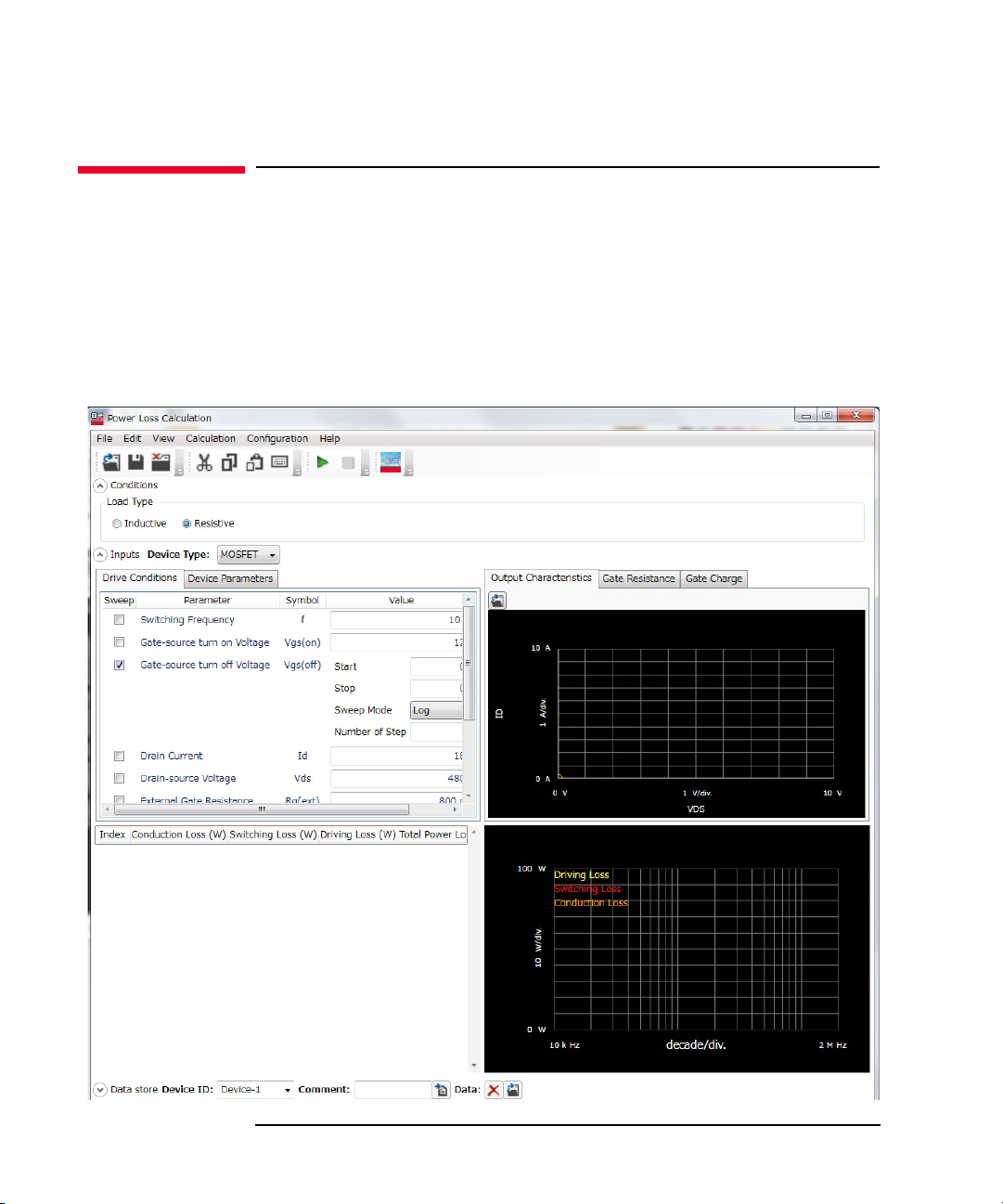
How To Perform Measurement
How To Calculate Power Loss
How To Calculate Power Loss
This section describes how to calculate the power loss at a switching device using
the power loss calculation software and consists of the following sub-sections:
• Calculating Power Loss
• Extracted Parameters By Power Loss Calculation
Figure 3-3 Power Loss Calculation So ftware
3- 18 Keysight B1507A User’s Guide, Ed ition 1
Page 97

The power loss calculation software calculates the power loss from the drive
conditions and the device characteristics parameters of DUT.
There are the following two ways to specify the parameters for calculation:
• Specify the parameter values from the datasheet of DUT.
If you want to calculate the power loss of DUT at the different drive conditions
or there are the parameters that are not specified in the datasheet, you may
specify the predicted values.
• Measure the switching device by the I/V measurement software, capacitance
measurement software, and gate charge measurement software at your desired
drive conditions and store the measurement data. Then, the power loss
calculation software read the stored measurement data and extract the required
drive conditions and characteristics parameters for power loss calculation.
This section explains the procedure that specify the measurement data file of DUT.
Calculating Power Loss
Step 1. Prepare the measurement data
How To Perform Measurement
How To Calculate Power Loss
The power loss calculation software uses the following measurement data files to
calculate the power loss. So, measure the DUT at your desired drive conditions and
save the measured data.
• Measurement data file of I/V measurement software
Prepare a measurement data file that measured either one of the following
measurement item.
•ID-VDS
•RDS-ID
• VDS-VGS
• RDS-VGS
• Measurement data file of capacitance measurement software
Prepare the measurement data files that measured the following measurement
items.
•Rg
•Crss
Keysight B1507A User’s Guide, Edition 1 3- 19
Page 98

How To Perform Measurement
How To Calculate Power Loss
• Measurement data file of gate charge measurement software
Prepare a measurement data file that measured any measurement item.
Step 2. On the software palette, click the Power Loss Calculation icon . The Power Loss
Calculation software (Figure 3-3) opens.
Step 3. Select the assumed load type to calculate the power loss in the Conditions area on
the work area.
Inductive Inductive load
Resistive Resistive load
Step 4. Specify the measurement data files to be used for power loss calculation and load
them.
1. Specify the measurement data file of the I/V measurement software to load.
a. Click the Output Characteristics tab at the right of work area to display the
Output Characteristics area.
3- 20 Keysight B1507A User’s Guide, Ed ition 1
Page 99

How To Perform Measurement
How To Calculate Power Loss
b. Click the Load Measurement Data button at the up per -left co rner o f the
Output Characteristics area.
After the dialog box opens, specify the measurement data of I/V
measurement software.
The characteristics graph of the loaded measurement item is displayed.
2. Specify the Rg measurement data file of the capacitance measurement software
to load.
a. Click the Gate Resistance tab to display the Gate Resistance area.
b. Click the Load Measurement Data button at the up per -left co rner o f the
Gate Resistance area.
After the dialog box opens, specify the Rg measurement data of capacitance
measurement software.
The loaded Rg characteristics graph is displayed.
3. Specify the Crss measurement data file of the capacitance measurement
software to load.
a. Click the Reverse Transfer Capacitance tab to display the Revers Transfer
Capacitance area.
b. Click the Load Measurement Data button at the up per -left co rner o f the
Reverse Transfer Capacitance area.
After the dialog box opens, specify the Crss measurement data of
capacitance measurement software.
The loaded Crss characteristics graph is displayed.
4. Specify the measurement data file of the gate charge measurement software to
load.
a. Click the Gate Charge tab to display the Gate Charge area.
b. Click the Load Measurement Data button at the up per -left co rner o f the
Gate Charge area.
After the dialog box opens, specify the measurement data of gate charge
measurement software.
The gate charge characteristics graph of the loaded measurement item is
displayed.
Keysight B1507A User’s Guide, Edition 1 3- 21
Page 100

How To Perform Measurement
How To Calculate Power Loss
For the drive conditions and the device parameters for power loss calculation that
extracted from the loaded measurement data, see “Measurement Data and Extracted
Drive Conditions and Device Parameters for Power Loss Calculation” on page 25”.
You can confirm or change the drive conditions for power loss calculation by
clicking the Drive Conditions tab at the left of work area.
Also, you can confirm or change the device parameters fo r power loss calculation by
clicking the Device Parameters tab.
Step 5. Select a drive condition or device parameter to be swept and specify the sweep
condition.
If you select a drive condition parameter to be swept, click the Drive Condition tab
and mark the check box of the desired drive parameter.
If you select a device parameter to be swept, click the Device Parameters tab and
mark the check box of the desired device parameter.
This example select a switching frequency to be swept.
1. Click the Drive Conditions tab and mark the check box of the Switching
Frequency parameter to select.
2. Specify the sweep condition in the Value column.
Start Sweep start value
3- 22 Keysight B1507A User’s Guide, Ed ition 1
 Loading...