

Page 1

Operating and
Service Guide
Keysight AC6800B
Basic
AC Sources
Series
Page 2

Notices 4
Copyright Notice 4
Manual Part Number 4
Edition 4
Published by 4
Warranty 4
Technology Licenses 4
U.S. Government Rights 5
Safety and Regulatory Information 6
General Information 6
Safety Warnings 6
Product Grounding 6
General Warnings 7
Environmental Warnings 7
Shock Hazard 8
Installation Warnings 9
Heavy Weight 9
Equipment Cautions 10
General Cautions 10
Installation Cautions 10
Operational Cautions 10
Moving Cautions 10
Safety Symbols 11
1Getting Started 13
Before Installation or Use 14
Introduction to the Instrument 19
Instrument Ratings 23
Installing an Optional Interface Board 24
Rack Mounting 25
Connecting the Power Cord 28
Switchboard and Circuit Breaker Requirements 32
Quick Start 35
Interface Connections 39
Remote Interface Configuration 41
Making Output Power Connections 51
Voltage Ranges and Limits 57
Error Checking and Soft Limits 59
2User Information 63
Welcome 64
Front Panel Menu Reference 66
General Front-Panel Organization 68
Selecting the Output Voltage Programming Source and Output Mode 71
Specifying Output Coupling 72
Programming AC Output 73
Programming DC Voltage 78
Setting Limit Values 79
2 Keysight AC6800B Series Operatingand Service Guide
Page 3

Turning the Output On and Off 81
Storing and Retrieving Instrument States 82
Configuring Instrument Preferences 84
Calibrating from the Front Panel 86
Configuring Overcurrent Protection 87
Configuring Watchdog Protection 88
Configuring and Clearing Measurements 89
Using External Analog Control 90
Viewing Error Messages 94
3SCPI Programming Reference 95
Introduction to SCPI 96
Status Overview 101
Command Quick Reference 106
ABORt Subsystem 115
CALibrate Subsystem 116
CURRent Subsytem 121
DISPlay Subsystem 123
FETCh and MEASure Subsystems 125
FREQuency Subsystem 130
HCOPy Subsystem 132
IEEE-488 Common Commands 133
INITiate Subsystem 139
LXISubsystem 140
OUTPut Subsystem 141
SENSe Subsytem 144
[SOURce:] Subsystem 145
STATus Subsystem 146
SYSTem Subsystem 151
TRIGger Subsystem 156
VOLTage Subsystem 159
Default Settings 165
SCPI Error Messages 166
4Calibration, Verification, and Service 169
Calibration Overview 170
Calibration Procedure 171
Performance Verification 177
Performance Test Records 185
Service 189
License Files 197
Keysight AC6800B Series Operating and Service Guide 3
Page 4

Notices
Notices
Copyright Notice
© Keysight Technologies, Inc. 2017
Manual Part Number
AC6800-90901
Edition
Edition 1, December 2017
Published by
Keysight Technologies, Inc.
550 Clark Drive, Suite 101
Budd Lake, New Jersey 07828
USA
Warranty
THE MATERIAL CONTAINED IN THIS DOCUMENT IS PROVIDED "AS IS," AND IS SUBJECT TO BEING
CHANGED, WITHOUT NOTICE, IN FUTURE EDITIONS. FURTHER, TO THE MAXIMUM EXTENT
PERMITTED BY APPLICABLE LAW, KEYSIGHT DISCLAIMS ALL WARRANTIES, EITHER EXPRESS OR
IMPLIED WITH REGARD TO THIS MANUAL AND ANY INFORMATION CONTAINED HEREIN, INCLUDING
BUT NOT LIMITED TO THE IMPLIED WARRANTIES OF MERCHANTABILITY AND FITNESS FOR A
PARTICULAR PURPOSE. KEYSIGHT SHALL NOT BE LIABLE FOR ERRORS OR FOR INCIDENTAL OR
CONSEQUENTIAL DAMAGES IN CONNECTION WITH THE FURNISHING, USE, OR PERFORMANCE OF
THIS DOCUMENT OR ANY INFORMATION CONTAINED HEREIN. SHOULD KEYSIGHT AND THE USER
HAVE A SEPARATE WRITTEN AGREEMENT WITH WARRANTY TERMS COVERING THE MATERIAL IN
THIS DOCUMENT THAT CONFLICT WITH THESE TERMS, THE WARRANTY TERMS IN THE SEPARATE
AGREEMENT WILL CONTROL.
Technology Licenses
The hardware and/or software described in this document are furnished under a license and may be
used or copied only in accordance with the terms of such license.
4 Keysight AC6800B Series Operating and Service Guide
Page 5

Notices
U.S. Government Rights
The Software is “commercial computer software,” as defined by Federal Acquisition Regulation
(“FAR”) 2.101. Pursuant to FAR 12.212 and 27.405-3 and Department of Defense FAR Supplement
(“DFARS”) 227.7202, the U.S. government acquires commercial computer software under the same
terms by which the software is customarily provided to the public. Accordingly, Keysight provides the
Software to U.S. government customers under its standard commercial license, which is embodied in
its End User License Agreement (EULA), a copy of which can be found at
http://www.keysight.com/find/sweula. The license set forth in the EULA represents the exclusive
authority by which the U.S. government may use, modify, distribute, or disclose the Software. The
EULA and the license set forth therein, does not require or permit, among other things, that Keysight:
(1) Furnish technical information related to commercial computer software or commercial computer
software documentation that is not customarily provided to the public; or (2) Relinquish to, or
otherwise provide, the government rights in excess of these rights customarily provided to the public
to use, modify, reproduce, release, perform, display, or disclose commercial computer software or
commercial computer software documentation. No additional government requirements beyond
those set forth in the EULA shall apply, except to the extent that those terms, rights, or licenses are
explicitly required from all providers of commercial computer software pursuant to the FAR and the
DFARS and are set forth specifically in writing elsewhere in the EULA. Keysight shall be under no
obligation to update, revise or otherwise modify the Software. With respect to any technical data as
defined by FAR 2.101, pursuant to FAR 12.211 and 27.404.2 and DFARS 227.7102, the U.S.
government acquires no greater than Limited Rights as defined in FAR 27.401 or DFAR 227.7103-5 (c),
as applicable in any technical data.
Keysight AC6800B Series Operating and Service Guide 5
Page 6

Safety and Regulatory Information
Safety and Regulatory Information
This procedure requires the user to send SCPI commands to the instrument. Connect to
the instrument via LAN or USB. Use the Keysight IO Libraries to send SCPI commands.
General Information
The equipment is for industrial use.
Equipment operators are subject to all applicable safety regulations. Along with the warning and
safety notices in this manual, all relevant safety, accident prevention, and environmental regulations
must also be followed. In particular, the operators of the equipment:
l Must be informed of the relevant safety requirements.
l Must have read and understood the operating manual before using the equipment.
l Must use the designated and recommended safety equipment.
The following general safety precautions must be observed during all phases of operation of this
instrument. Failure to comply with these precautions or with specificwarnings or instructions
elsewhere in this manual violates safety standards of design, manufacture, and intended use of the
instrument. Keysight Technologies assumes no liability of the customer’s failure to comply with the
requirements.
Safety Warnings
A WARNING notice denotes a hazard. It calls attention to an operating procedure, practice, or the like
that, if not correctly performed or adhered to, could result in personal injury or death. Do not proceed
beyond a WARNINGnotice until the indicated conditions are fully understood and met.
Should network communication issues occur, the instrument settings shown in the
Browser Web Control page may not represent the actual state of the instrument. This may
result in unexpected hazardous voltages on the output and sense connections that could
result in personal injury, death, or damage to a device under test. Before touching the output or sense connections or connecting to a device under test, always verify the state of
the instrument.
Product Grounding
The instrument is a Class 1 product and is provided with a grounding-type power cord set.
The instrument chassis and cover are connected to the instrument electrical ground to
minimize shock hazard. The groundpin of the cordset plug must be firmly connected to
the electrical ground (safety ground)terminal at the power outlet. Any interruption of the
protective earth (grounding)conductor or disconnection of the protective earth terminal
will cause a potential shock hazard that could result in personal injury or death.
6 Keysight AC6800B Series Operating and Service Guide
Page 7

Safety and Regulatory Information
General Warnings
Do not use this product in any manner not specified by the manufacturer. The protective
features of this product may be impaired ifit is used in a manner not specified in the
operation instructions.
Instruments that appear damaged or defective should be made inoperative and secured
against unintended operation until they can be repaired by qualified service personnel.
The instrument contains an internal fuse, which is not user accessible.
DO NOT REMOVE COVERS. NO OPERATOR SERVICEABLE PARTS INSIDE. REFER
SERVICING TO QUALIFIED SERVICE PERSONNEL.
SECURELY TURN OFF THE CIRCUIT BREAKER ON THE SWITCHBOARD BEFORE
HANDLING THE POWER CORDS. TO AVOID ANELECTRIC SHOCK, THE PROTECTIVE
CONDUCTOR TERMINAL MUST BE CONNECTED TO AN ELECTRICAL GROUND.
NE PAS RETIRER LES COUVERTURE DE LA BOITE. AUCUN OPÉRATEUR SERVICEABLE
PIÈCES À L'INTÉRIEUR. CONFIER L'ENTRETIEN DE PERSONNELQUALIFIÉ.
CORRECTEMENT COUPER LEDISJONCTEUR ARMOIREAVANT DE MANIPULER LES
CORDONS D'ALIMENTATION. POUR ÉVITER TOUT CHOC ÉLECTRIQUE, LE
CONDUCTEUR DEPROTECTION BORNE DOIT ÊTRE RELIÉE À UNE MASSE ÉLECTRIQUE.
Environmental Warnings
This product is designed for safe indoor use. Use indoors only.
Do not operate the instrument near flammable gases or fumes.
To prevent the possibility of explosion or fire, do not use the product near alcohol, thinner
or other combustible materials, or in an atmosphere containing such vapors.
Do not install the product near a heater, in direct sunlight, or in areas subject to drastic
temperature changes. The operating temperature range is 0 to 40 °C (32 to 104 °F), and
the storage temperature range is -10 to 60 °C (14 to 140 °F).
Do not install the product in high-humidity locations, such as near a boiler, humidifier, or
water supply. The operating humidity range is 20% to 80% relative humidity (no
condensation), and the storage humidity range is 90% relative humidity or less (no
condensation). Condensation may occur even within the operating humidity range. In
such cases, do not use the instrument until the condensation dries up completely.
Do not install the product in a corrosive atmosphere or in environments containing
sulfuric acid mist, etc. This may cause corrosion of various conductors and bad contacts of
connectors inside the instrument leading to malfunction and failure, or in the worst case,
a fire.
Do not install the product in a dusty location. Accumulation of dust can lead to electric
shock or fire.
Keysight AC6800B Series Operating and Service Guide 7
Page 8

Safety and Regulatory Information
Shock Hazard
Before making any load or sense connections be sure to turn the POWER switch off and
remove the power plug from an outlet or turn off the circuit breaker of switchboard.
When the power switch is turned offwhile the output is on, residual voltage still remains
at the output terminals.
Do not touch the output terminal block for at least 20 seconds after the power switch is
tuned off.
When installing the switch between the OUTPUT terminal block and the load, be sure to
turn the POWER switch offand remove the power plug from an outlet or turn off the circuit
breaker ofthe switchboard.
Be sure to turn the switch off before connecting the load to the terminal at the load end of
the switch.
Do not touch the switch terminal or the output terminal when the output is on.
Do not remove the instrument covers. There are no customer-serviceable parts inside.
Some circuits are active and have power briefly after the power switch is turned off.
To prevent electric shock, unplug the unit before cleaning.
For protection from electrical shock, the power cordground must not be defeated. If only
a two-contact electrical outlet is available, connect the instrument’s chassis ground
screw (see above) to a good earth ground.
This product is an IEC Safety Class I equipment (equipment with a protective conductor
terminal). Be sure to ground (earth) the unit.
Connect the protective conductor terminal to earth ground.
In DC mode, L is at positive potential and Nis at negative potential when setting the
positive value. The opposite is true when setting the negative value.
Do not use the terminal block with the terminal cover removed.
Turn off the switchboard circuit breaker before connectingthe cord.
This product includes protective earth terminals. To minimize shock hazard, the
instrument must be connected to the AC power mains through a grounded power cable,
with the ground wire firmly connected to an electrical ground (safety ground)at the power
outlet. Any interruption of the protective (grounding)conductor or disconnection of the
protective earth terminal will cause a potential shock hazard that could result in personal
injury.
If a capacitor, battery, or similar device is connected as a load in DC mode, voltage
remains at the section connected to the output terminal block even when the output is off
until the load energy is discharged. The discharge time of the internal capacitor when no
load is connected is approximately 0.1 seconds. To prevent the possibility of electric
shock, do not touch the output terminal block.
8 Keysight AC6800B Series Operating and Service Guide
Page 9

Safety and Regulatory Information
Installation Warnings
Have a qualified engineer connect the power cord to the switchboard.
Protective circuits inside the instrument, including input fuses, are connected to match
the input terminal polarity. Make sure the colors of the wires connected to the input
terminals (L,N,andGND) are correct.
Verify that all safety precautions are taken. Make all connections to the unit before
applying power. Note the instrument's external markings described under "Safety
Symbols."
You cannot use standard rack mounting support rails, as they would block the airflow
needed for cooling.
Heavy Weight
Danger to hands and feet. To avoid personal injury and damage to the instrument, always
use a sturdy cart or other suitable device to move the instrument. Do not lift the
instrument alone; always use two people to lift the instrument.
Keysight AC6800B Series Operating and Service Guide 9
Page 10

Safety and Regulatory Information
Equipment Cautions
A CAUTION notice denotes a hazard. It calls attention to an operating procedure, practice, or the like
that, if not correctly performed or adhered to, could result in damage to the product or loss of
important data. Do not proceed beyond a CAUTION notice until the indicated conditions are fully
understood and met.
General Cautions
Do not place objects on the instrument. Placing objects, especially heavy objects, on top
of the product can cause failures.
Installation Cautions
Do not block the air intake at the front of the instrument or the exhaust at the rear.
Large voltage distortion on the AC power line can lead to malfunction. Do not connect the
instrument to a generator or a similar device.
Do not use the product in a location where strong magnetic or electric fields are nearby or
a location where large amounts of distortion or noise are present on the input power
supply waveform. The product may malfunction.
Do not install the product on an inclined surface or location subject to vibrations. The
product may fall or tip over, causing damage or injuries or both.
Operational Cautions
You cannot set the voltage limit when the instrument is being controlled by external
analog signals. An excessive external voltage may damage the load.
When the output is turned on, several volts of undershoot or overshoot may appear for a
time period on the order of ten microseconds.
Moving Cautions
Be sure to include this manual when transporting the instrument.
Turn off the power switch before moving the instrument. Moving the product while the
power is turned on can cause electric shock or instrument damage.
Remove all wiring before moving the instrument. Moving the product with the cables
connected can cause wires to break or injuries due to the product falling over.
When transporting the product, be sure to use the original packingmaterials. Damage
may result from vibrations or from the product falling during transportation.
10 Keysight AC6800B Series Operating and Service Guide
Page 11

Safety Symbols
Direct current
Alternating current
Frame or chassis terminal
Standby supply. Unit is not completely disconnected fromAC mains
when switch is off.
Caution, risk of electricshock
Caution, refer to accompanying documents
Earth ground terminal
Safety and Regulatory Information
ISM1-A
ICES/NMB-001
ICES/NMB001
The CE mark is a registered trademark of the European Community. The
text indicates that the instrument is an Industrial Scientific and Medical
Group 1 Class A product (CISPR 11, Clause 4).
The TUV mark is a registered trademark of the European community.
This mark indicates product compliance with the Canadian Interference- Causing Equipment Standard.
The C-tick mark is a registered trademark of the Spectrum Management Agency of Australia. This signifies compliance with the Australian EMC Framework regulations under the terms of the Radio
Communications Act of 1992.
South Korean Class A EMC Declaration
This equipment is Class A suitable for professional use and is for use in
electromagnetic environments outside of the home.
Contains one or more of the 6 hazardous substances above the maximum concentration value (MCV), 40 Year EPUP.
This ISM device complies with Canadian ICES-001. Cet appareil ISM est
conforme à la norme NMB-001 du Canada.
Keysight AC6800B Series Operating and Service Guide 11
Page 12

Safety and Regulatory Information
Waste Electrical and Electronic Equipment (WEEE)
This product complies with the WEEE Directive) marketing requirement. The affixed product label (see
below) indicates that you must not discard this electrical/electronic product in domestic household
waste.
Product Category: With reference to the equipment types in the WEEE directive Annex 1, this product
is classified as “Monitoring and Control instrumentation” product. Do not dispose in domestic
household waste.
To return unwanted products, contact your local Keysight office, or see
about.keysight.com/en/companyinfo/environment/takeback.shtml for more information.
South Korea Class A EMC declaration
Information to the user:
This equipment has been conformity assessed for use in business environments. In a residential
environment this equipment may cause radio interference.
This EMC statement applies to the equipment only for use in business environment.
12 Keysight AC6800B Series Operating and Service Guide
Page 13

Keysight AC6800B Series Operating and Service Guide
1 Getting Started
Before Installation or Use
Introduction to the Instrument
Instrument Ratings
Installing an Optional Interface Board
Rack Mounting
Connecting the Power Cord
Switchboard and Circuit Breaker Requirements
Quick Start
Interface Connections
Remote Interface Configuration
Making Output Power Connections
Voltage Ranges and Limits
Error Checking and Soft Limits
Page 14

1Getting Started
Before Installation or Use
Inspect the Unit
When you receive your instrument, inspect it for obvious shipping damage. If there is damage, notify
the shipping carrier and nearest Keysight Sales and Support Office immediately. Refer to
www.keysight.com/find/assist. Save all packingand shipping materials in case the unit must be
returned or moved.
Check for Items Supplied
Verify that you received the following items.
AC6800B Series AC Source
Line cord (AC6801B only)
AC input cover (AC6803B and AC6804B only)
Ferrite core and cable tie (two supplied with AC6803B)
CD -IO Libraries Media Suite
Safety Information booklet
Certificate Of Calibration and envelope
Refer to the boxcontents list for any additional items that may be included with your shipment. If
anything is missing, please contact your nearest Keysight Sales and Support Office.
Review Safety Information
This AC source is a Safety Class 1 instrument, which means it has a protective earth terminal. That
terminal must be connected to earth ground through a power source equipped with an earth ground.
Refer to the Safety Notices for general safety information. Before installation or operation, check the
instrument and review this guide for safety warnings and instructions. Safety warnings for specific
procedures are located at appropriate places throughout this guide.
14 Keysight AC6800B Series Operating and Service Guide
Page 15

1Getting Started
Observe Environmental Conditions
Do not operate the instrument near flammable gases or fumes.
The AC6800B Series instruments are Overvoltage Category II instruments that should only be
operated in a controlled, indoor environment subject to the following restrictions:
Operating: 0 to 40 °C (32 to 104 °F), 20% to 80% relative humidity, noncondensing
Storage: –10 to 60 °C (14 to 140 °F), 90% or less relative humidity, noncondensing
Altitude: Up to 2000 m
Provide Adequate Air Flow
Do not block the air intake at the front of the instrument or the exhaust at the rear.
The dimensions of each model are shown below. Fans cool the instrument by drawing air through the
front and exhausting it out the back. Allow at least 8 inches (20 cm) of space at the front and back of
the unit for air circulation.
All dimensions are in mm.
AC6801B
Keysight AC6800B Series Operating and Service Guide 15
Page 16

1Getting Started
AC6802B
16 Keysight AC6800B Series Operating and Service Guide
Page 17

AC6803B
1Getting Started
Keysight AC6800B Series Operating and Service Guide 17
Page 18

1Getting Started
AC6804B
18 Keysight AC6800B Series Operating and Service Guide
Page 19

Introduction to the Instrument
Front Panel at a Glance
Front Panel Display at a Glance
Rear Panel at a Glance
Instrument Ratings
Front Panel at a Glance
1Getting Started
The following table lists the main parts of the front panel, from left to right:
The [Power] switch turns the unit on or off. The indicator next to this switch
shows the display status. Green indicates normal operation. Yellow indicates that
the display is in screen saver mode or that the instrument is in the boot-up process. Press any key to exit screen saver mode.
The status LEDs light to indicate when a protection event has occurred and when
the output is on.
The display allows you to configure and monitor the instrument.
Keysight AC6800B Series Operating and Service Guide 19
Page 20

1Getting Started
[Meter] returns the display to metering mode. Pressing it repeatedly cycles the
display through all three formats (METER_VI, METER_VIP, and METER_ALL).
[Menu] opens the top level of the command menu. Pressing it a second time
returns to the metering mode display.
[Protect] brings the user to the Protect menu. This is equivalent to
[Menu]>Protect.
[Back] backs out of a menu without activating any changes.
[Help] describes the displayed menu control.
[Error] displays messages in the error queue.
The [Error] and [Help] keys provide access to text that is accessed
via a vertically scrolling text box. Use the up and down arrow keys
to scroll through multiline text, one screen at a time.
To retrieve error messages remotely, send the SYSTem:ERRor?
query. The SCPI Status Byte and Standard Event Registers provide
an overview of error conditions.
The puqt arrows move around the command menus and select characters in
alphanumeric entry fields. The [Select] key makes a selection in a menu and
enters the edit mode for numeric parameters.
[On/Off] enables or disables the output.
[Voltage] specifies the voltage settings.
[Freq] specifies the frequency settings.
[0] through [9] enter numbers.
[.] enters the decimal point.
[–] toggles between positive and negative numbers.
[!] and [#] increment or decrement voltage or frequency settings and select letters
in alphanumeric entry fields.
[E] enters the letter E to allow you to enter an exponent to the right of it.
[-] backspaces to delete characters.
[Enter] enters a value. If you exit a field without pressing [Enter], the value is
ignored.
20 Keysight AC6800B Series Operating and Service Guide
Page 21

Front Panel Display at a Glance
Metering field Shows the measured output.
Status field Displays the instrument status:
OFF = the output is off.
CV = the output is in constant voltage mode.
OC = the output is disabled by the overcurrent protection.
OT = the overtemperature protection has tripped.
OP = the overpower protection has tripped.
CLPK = the instrument has gone beyond its peak current limit.
CLrms = the instrument has gone beyond its RMS current limit.
PL = the instrument has gone beyond its power limit.
SF = the output is disabled by a sense fault protection
WDG = watchdog protection - no I/O activity.
1Getting Started
Range field Displays the current voltage range (HIGH, LOW, or AUTO).
Settings field Displays the output settings.
Interface field Indicates the following remote interface activity:
Err = an error has occurred (press [Error] to display the error message)
Lan = the LAN is connected and has been configured
IO = there is activity on one of the remote interfaces
Keysight AC6800B Series Operating and Service Guide 21
Page 22

1Getting Started
Rear Panel at a Glance
For protection from electrical shock, the power cordground must not be defeated. If only a
two-contact electrical outlet is available, connect the instrument’s chassis ground screw
(see above) to a good earth ground.
AC6801B
AC6802B
AC6803B
AC6804B
22 Keysight AC6800B Series Operating and Service Guide
Page 23

1Getting Started
Instrument Ratings
AC6801B AC6802B AC6803B AC6804B
Output Rating for AC mode (155 V/310 V range)
Rated voltage range 1 to 155 Vrms/2 to 310 Vrms
Maximum rms current 5 A/2.5 A 10 A/5 A 20 A/10 A 40 A/20 A
Maximum power 500 VA 1 kVA 2 kVA 4 kVA
Frequency range 40 Hz to 500 Hz
Output Rating for DC mode (155 V/310 V range)
Rated voltage range 1.4 to 219 Vrms/2.8 to 438 Vrms
Maximum DC current 4 A/2 A 8 A/4 A 16 A/8 A 32 A/16 A
Maximum power 400 VA 800 VA 1.6 kVA 3.2 kVA
Input Ratings
Voltage rating
Voltage range
100 to 120 Vrms/200 to 240 Vrms, 50 Hzor 60 Hz, single-phase
90 to 132 Vrms/180 to 264 Vrms (auto detected when thepower is turned on)
Frequency range
Apparent power
800 VA or less 1600 VA or less 3200 VA or less 6400 VA or less
Power factor
Maximum input current
8 A/4A @ 100V/200V
6.7A/3.5A@ 120V/230V
Environment
Operating environment
Temperature and humidity range
0 to 40 °C (32 to 104 °F), 20% to 80% R.H. non-condensing
Altitude
Acoustic noise
Physical
Dimensions (with safety covers) 428 × 128 × 350 mm
168.5 x 50.5 x 138”
Weight Approx. 8 kg
(17.64 lb)
47 Hzto 63 Hz
0.9 (typical)
16 A/8A @ 100V/200V
13.4A/7.0 A@ 120/230V
Indoor use, OvervoltageCategory II
Up to 2000 meters
428 × 128 × 350 mm
168.5 x 50.5 x 138”
32A/16A@ 100V/200V
26.8A/14.0 A @ 120/230V
< 70 dbA
428 × 128 × 550 mm
169 x 50.5 x 216.5”
Approx. 11 kg
(24.25 lb)
Approx. 16 kg
(35.27 lb)
64 A/32A @ 100V/200V
53.6A/28.0 A @ 120/230V
428 × 256 × 600
mm\168.5"×101"×236")
Approx. 32 kg
(70.55 lb)
Input terminal IEC 320 inlet M4 terminal block M6 terminal block M6 terminal block
Output terminal M4 terminal block M4 terminal block M4 terminal block M6 terminal block
Keysight AC6800B Series Operating and Service Guide 23
Page 24

1Getting Started
Installing an Optional Interface Board
The rear-panel slot can hold either the GPIB interface board (option AC68GPBU) or the analog output
interface board (option AC68BALGU).
Consult with your Keysight sales representative or distributor for information regarding the
availability of option AC68BALGU.
To install a board:
1.
Check that the power switch is turned off.
2.
Touch the grounded metal to discharge your static electricity.
3.
Unscrew the slot cover screws and remove the cover. Retain the cover for use in case the interface
board is ever removed.
4.
Verify that the switch at the bottom rear of the slot is in the up position. It should only be down during
the firmware update process.
5.
Slide the board all the way into the connector at the back of the slot.
6.
Use the slot cover screws to secure the board.
24 Keysight AC6800B Series Operating and Service Guide
Page 25

1Getting Started
Rack Mounting
This section requires option AC68BRAC3 (for models AC6801B, AC6802B, and AC6803B)
or AC68BRAC6 (for model AC6804B).
This section contains instructions for installing the instruments in a 19-inch EIA rack.
Verification of Option Kit
Verify that you received the following items. If anything is missing, please contact your nearest
Keysight Sales and Support Office.
Rack Mounting Kit AC68BRAC3 for AC6801B, AC6802B, and AC6803B
Item Description Quantity
1 Bracket 2
2 Flat Head Screws M4×0.7×10 4
3 Clip Nuts for Rack Frame 10-32 0.5-in. 4
4 Dress Screws with Nylon Washer, Phantom Gray 4
Rack Mounting Kit AC68BRAC6 for AC6804B
Item Description Quantity
1 Bracket 2
2 Flat Head Screws M4×0.7×10 8
3 Clip Nuts for Rack Frame 10-32 0.5-in. 8
4 Dress Screws with Nylon Washer, Phantom Gray 8
Installation
Do not block the air intake at the front of the instrument or the exhaust at the rear.
To prevent the instrument from falling, install suitable support angles (not included)
to support the instrument as shown.
Keysight AC6800B Series Operating and Service Guide 25
Page 26

1Getting Started
Rack Mounting Models AC6801B, AC6802B, and AC6803B
Remove the feet from the bottom
panel.
Using the accompanying M4×10
flat head screws, install the brackets.
Using the accompanying dress
screws and clipnuts (10-32),
mount the instrument in the rack.
26 Keysight AC6800B Series Operating and Service Guide
Page 27

Rack Mounting Model AC6804B
Remove the feet from the bottom panel.
Using the accompanying M4×10 flat head
screws, install the brackets.
1Getting Started
Using the accompanying dress screws and clip
nuts (10-32), mount the instrument in the rack.
Keysight AC6800B Series Operating and Service Guide 27
Page 28

1Getting Started
Connecting the Power Cord
The power cord used with the product varies depending on the model. This product complies with IEC
Overvoltage Category II (energy-consuming equipment supplied from a fixed installation).
The AC6801B line cordhas a molded plug on both ends.
The AC6802B is a single-phase, cord-connected device that requires a plug
and cord set.
The AC6802B line cordmust have a plug on the utility side; you cannot hard
wire the instrument to the utility.
Possible Electric Shock
This product is an IEC Safety Class I equipment (equipment with a protective
conductor terminal). Be sure to ground(earth) the unit.
Connect the protective conductor terminal to earth ground.
AC6801B
Connect the power cord to the AC connector on the back of the instrument. Then connect the other
end to a properly grounded power outlet. You will use this plug to disconnect from mains power.
Use the supplied power cordto connect to the AC line. If the supplied power cordcannot be used due
to the rated voltage or the plug shape, have a qualified engineer replace it with an appropriate power
cord of length 3 m or less. If obtaining a power cord is difficult, contact Keysight.
The power cord with a plug can be used to disconnect the instrument from the AC line in an
emergency. Connect the plug to an easily accessible power outlet so that the plug can be removed
from the outlet at any time. Be sure to allow enough space around the power outlet.
To connect the power cord:
1. Check that the AC power supply meets the instrument's nominal input rating, which is any nominal
voltage from 100 to 120 VAC or 200 to 240 VAC. The frequency is 50 or 60 Hz.
Large voltage distortion on the AC power line can lead to malfunction. Do not
connect the instrument to a generator or a similar device.
2. Check that the power switch is turned off.
3. Connect the power cordto the AC input receptacle on the rear panel.
4. Insert the power plug into an outlet.
28 Keysight AC6800B Series Operating and Service Guide
Page 29

1Getting Started
AC6802B, AC6803B, and AC6804B
The AC6802B requires use of a flexible plug and cord set which must be supplied by the user. The line
cord must have a plug on the utility side; you cannot hard-wire the instrument to utility mains.
The AC6803B and AC6804B instruments may be connected either by a flexible plug and cord set
supplied by the user or may, alternatively, be hard wired to the utility mains. See Switchboard and
circuit breaker requirements for guidance on branch circuit and circuit breaker sizing.
A switchboard circuit breaker disconnect must be provided when connecting
AC6803B and AC6804B models, regardless of whether the connection is
made with a flexible cord or by hard wiring the device to the AC utility.
Possible Electric Shock
Turn offthe switchboard circuit breaker before connecting the cord.
Do not use the terminal blockwith the terminal cover removed.
Possible Fire
Have a qualified engineer connect the power cord to the switchboard.
Make sure connections are correct
Protective circuits inside the instrument, including input fuses, are connected
to match the input terminal polarity. Make sure the colors of the wires connected to the input terminals (L,N, andGND) are correct.
1. Check that the AC power supply meets the instrument's nominal input rating, which is any nominal
voltage from 100 to 120 VAC or 200 to 240 VAC. The frequency is 50 or 60 Hz.
Large voltage distortion on the AC power line can lead to malfunction. Do
not connect the instrument to a generator or a similar device.
2. Check that the power switch is turned off.
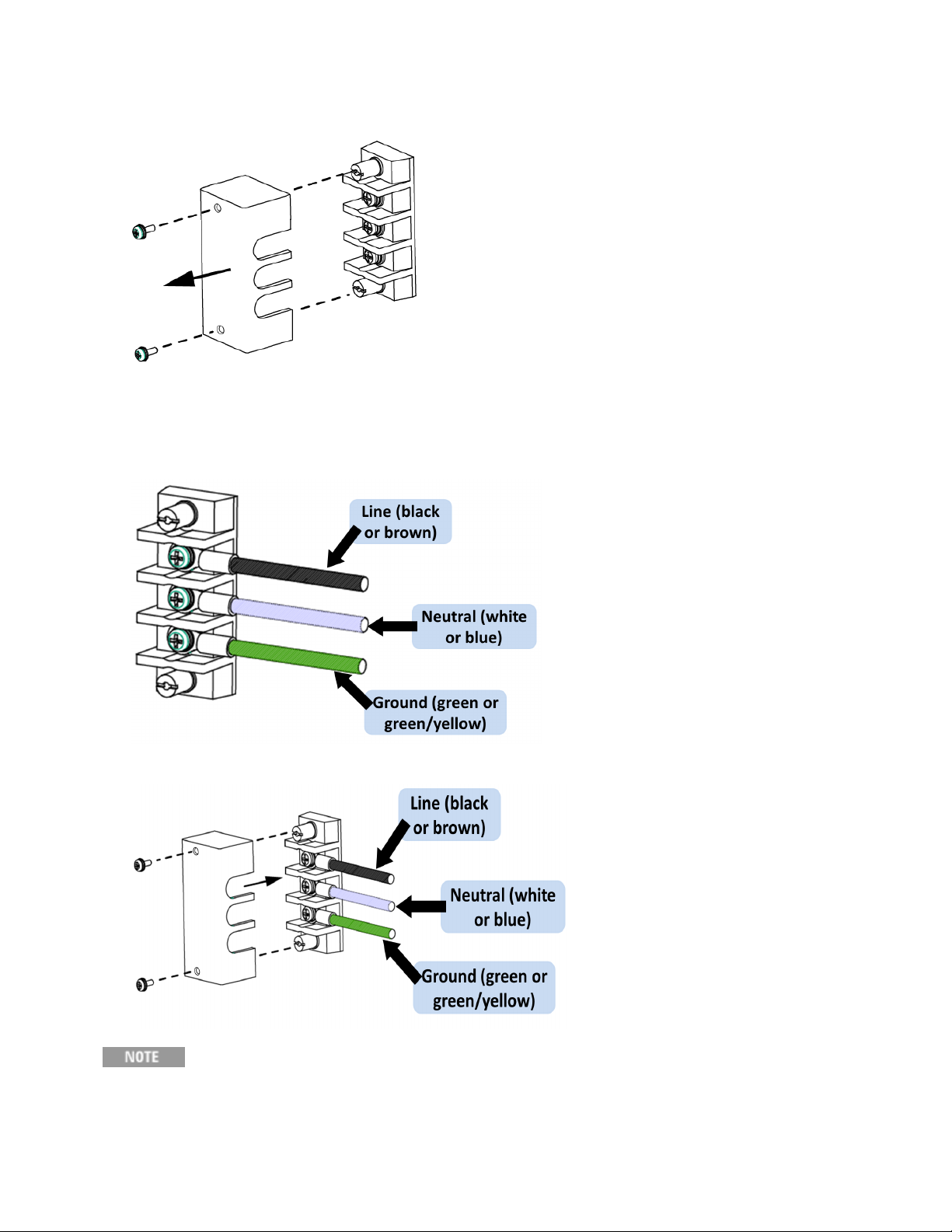
3. On Model AC6802B, remove the terminal cover and cable clamp attached to the AC Input terminal
block.
Keysight AC6800B Series Operating and Service Guide 29
Page 30

1Getting Started
4. Securely connect the power cord to match the L (line), N(neutral), and GND (ground)of the AC
Input terminal block. The protective earth terminal (ground)requires an extra length of wire compared
to the Line and Neutral wires. Always connect the ground wire first.
5. Install the terminal cover over the terminal block.
AC6802B
Place the cord inside the cable clamp and attache the clamp as shown:
30 Keysight AC6800B Series Operating and Service Guide
Page 31

1Getting Started
AC6803B
Install one of the two ferrite cores shipped with the unit close to the power cord strain relief as shown:
AC6804B
Attach crimp terminals to the switchboard end of the power cord (the end without terminals). For
termination, attach a crimp-style terminal to each wire that meets the terminal screws of the
switchboard to be connected, and then securely connect the wires to the terminal screws.
Connection must be performed by qualified personnel.
Turn off the switchboard.
Connect the power cord to match the L, N, and GND ofthe switchboard.
Keysight AC6800B Series Operating and Service Guide 31
Page 32

1Getting Started
Switchboard and Circuit Breaker Requirements
Turn off the switchboard circuit breaker to disconnect the instrument from the AC line in an
emergency. The breaker must be suitably located and easily reached, and it must be
marked as the disconnecting device for the equipment.
This section is provided for guidance only; consult with local experts to ensure strict
compliance with all local electrical code and safety requirements. These requirements
take precedence over any guidance provided in this section.
Please note the following switchboard and circuit breaker requirements.
Rated current:
AC6802B: 20 A
AC6803B: 40 A
AC6804B: 80 A
Dedicate the circuit breaker for the AC6802B, AC6803B, and AC6804B.
Keep the switchboard easily accessible at all times.
Apply a label to the switchboard, clearly identifyingthe disconnecting device and its associated
model, as shown below:
The tables below provides information about worst case current consumption for all AC6800B Series
models for various nominal AC mains voltages. Entries are obtained by dividing the worst case power
consumption (in VA) by the nominal mains voltage and rounding to the next highest integer value. Line
currents for other nominal voltages may be calculated similarly.
32 Keysight AC6800B Series Operating and Service Guide
Page 33

Maximum Input VA
AC6801B AC6802B AC6803B AC6804B
Input VA(Max) 800 1600 3200 6400
Approximate Maximum Current
Line Voltage AC6801B AC6802B AC6803B AC6804B
100 8 16 32 64
120 7 13 27 53
200 4 8 16 32
208 4 8 15 31
230 3 7 14 28
240 3 7 13 27
Breakers
1Getting Started
Different regions of the world have different sizing requirements for branch circuit conductors and
circuit breakers. In Europe and other regions where IEC standards apply, circuits breakers generally
are rated at 100% utilization, meaning that a device connected to a dedicated branch circuit may draw
a maximum current up to the circuit breaker rating. In the United States, the NEC generally specifies
what is known as the "80% rule" which requires branch circuits to be rated at 1.25 times the maximum
nameplate rating of the connected device.
Standard circuit breaker sizes also vary by region. The table below provides guidance for circuit
breaker sizing for various nominal mains voltages. The guidance for North American mains voltages
(120, 208, and 240 V) includes the 1.25 factor associated with the 80% rule. Guidance for the other
voltages (100, 200, and 230 V) assumes 100% utilization. By comparing the table above with the table
below, it may be seen that for the AC6801B and AC6802B models, the smallest standard size breaker
affords more than enough capability to supply the device. The AC6803B and AC6804B products drawn
higher currents and therefore are more likely to require higher breaker current ratings and dedicated
circuits.
For convenience, notes below the table give standard breaker sizes per IEC/EN 60898-1 and the NEC
for the United States.
Consult with local authorities to ensure full compliance with electrical code and safety requirements
before connecting any AC6800B Series instrument.
Breaker Sizes
Line Voltage AC6801B AC6802B AC6803B AC6804B
100 15 20 35 70
120 15 20 40 70
200 15 15 20 35
Keysight AC6800B Series Operating and Service Guide 33
Page 34

1Getting Started
Line Voltage AC6801B AC6802B AC6803B AC6804B
208 15 15 20 40
230 16 16 16 32
240 15 15 20 40
IEC 60898-1 and European Standard EN 60898-1 Standard Sizes
6, 10, 13, 16, 20, 25, 32, 40, 50, 63, 80, and 100 A
NEMA Standard Sizes (also commonly used in Japan)
15, 20, 25, 30, 35, 40, 45, 50, 60, 70, 80, 90, and 100 A
34 Keysight AC6800B Series Operating and Service Guide
Page 35

1Getting Started
Quick Start
Turn the Unit On and Off
Use the Menu System
Enter Numeric and Alphanumeric Values
Set the Output Voltage
Set the Output Current Limit
Enable the Output
Use Built-in Help System
Turn the Unit On and Off
To turn the instrument on:
1. Check that the power switch is turned off (O) and that nothing is connected to any output terminal
block on the instrument.
2.
Check that the power cord is of the correct type and correctly connected.
3. Push the (l) side of the power switch. If any unusual sound, unusual odor, fire, or smoke isperceived,
remove the power plug from the outlet or turn off the switchboard.
4.
The display lights up after a few seconds. An automatic power-on self-test ensures that the instrument
is operational.
It takes about 10 seconds for the instrument to initialize before it is ready for
use.
If the instrument does not turn on, verify that the power cord is firmly connected (power-line voltage is
automatically sensed at power-on). Also make sure that the instrument is connected to an energized
power source. If the LED next to the power switch is off, there is no AC power connected. If the LED is
amber, the instrument is in standby mode with AC power connected, and if it is green, the instrument
is on.
If a self-test error occurs, a message is displayed on the front panel. For other self-test errors, see
Service and Maintenance for instructions.
Push the (O)side of the POWER switch to turn the instrument off.
Keysight AC6800B Series Operating and Service Guide 35
Page 36

1Getting Started
Use the Menu System
Press the [Menu] key to access the top level of the command menu, shown below.
The first line displays the menu path (Menu:\), and the second line indicates the items that are
available at the present menu level (Output, Measure, and so on). The thirdline indicates the items
under the highlighted function in the second line.
Use the left and right navigation keys to move across the menu items, and press [Select] to select the
highlighted item and move to the next menu level.
The lowest menu level programs the selected item. Use the navigation keys to select an item. Use the
numeric entry keys to enter a value, then press [Enter]. Press [Help] at the lowest menu level for
detailed help.
Press [Back] to back out of a menu level without saving changes, and press [Menu] to return to the top
menu level without saving changes.
Press [Meter] to return to Meter View.
Enter Numeric and Alphanumeric Values
When the focus is on a text box, its label is highlighted within a dashed outline and its present value is
displayed in white text on a dark background. Pressing any key on the numeric keypad erases the
existing value and allows you to type the rest of the number. Use the [u] and [t] keys to move the
cursor. Press the [-] key to erase the character to the left of the cursor.
To enter letters or other non-numeric characters, such as when entering a DNS host name in
[Menu]>System>IO>LAN>Modify>Name, use the up and down arrows to scroll through the list of
characters.
When finished, press either [Enter] or [Select] to enter the data.
In general, pressing [Enter] or [Select] after entering a value into a text boxcauses the new value to
become effective immediately. The exceptions to this rule are when you change the values in
[Menu]>Output>Voltage>AC, [Menu]>Output>Voltage>DC, and [Menu]>Output>Frequency.
These require you to select the DONE button and press [Enter].
36 Keysight AC6800B Series Operating and Service Guide
Page 37

1Getting Started
Set the Output Voltage
Method 1
Press [Menu]>Output>Voltage, then choose AC or DC.
Use the left and right navigation keys to navigate to the setting to be changed.
In the following display, the voltage setting is selected. Enter the desired setting using the numeric
keypad. Then press [Select]. Use the arrows to navigate to the DONE button and press [Enter].
You can also use the [!] and [#] keys to adjust the value. Values take effect when the output is turned
on.
Method 2
Press [Voltage] to select the voltage entry field. Enter the desired setting using the numeric keypad.
Then press [Enter].
If you make a mistake, either use the backspace key to delete the number, press [Back] to back out of
the menu, or press [Meter] to return to meter mode.
Set the Output Current Limit
To limit the output current, press [Menu]>Output>Current.
Use the [Select] key to enable or disable latching. Specify the AC and DC current limits, and press
[Enter] to save your changes or [Back] to discard them.
If Enable Latching is checked, a current limitingevent longer than approximately three seconds will
disable the output and indicate OC protection fault. If this box is not checked, a current limitingevent
will decrease the output voltage until the current goes below the limit.
Enable the Output
Press On/Off to enable the output. If a load is connected to the output, the front panel display will
indicate that it is drawing current. Otherwise, the current reading will be zero. The status indicator
shows the output’s status.
For a description of the status indicators, refer to Front Panel Display at a Glance.
Keysight AC6800B Series Operating and Service Guide 37
Page 38

1Getting Started
Use Built-in Help System
View help
Press [Help] to view help at any time. If you are at a menu screen, you will get help for navigating
through the menus, and if you are at a screen that allows you to view or edit settings, you will get help
pertaining to those particular settings.
Press any key other than a navigation arrow to exit Help.
View the help information for displayed messages.
Whenever a limit is exceeded or any other invalid configuration is found, the instrument will display a
message, including error code information.
Press any key other than a navigation arrow to exit Help.
38 Keysight AC6800B Series Operating and Service Guide
Page 39

1Getting Started
Interface Connections
GPIB Connection
USB Connection
LAN Connection
This section describes how to connect to the instrument's various communication interfaces. For
additional information, refer to Remote Interface Configuration.
To begin, please install the Keysight IO Libraries Suite from the Keysight Automation-Ready CD that is
shipped with your instrument.
For detailed interface connection information, refer to the USB/LAN/GPIB Interfaces
Connectivity Guide, located on the Keysight Automation-Ready CD.
GPIB Connection
1.
Connect your computer to your instrument's optional GPIB interface card using a GPIB interface
cable.
2.
Use the Connection Expert utility of the Keysight IO Libraries Suite to connect to the installed GPIB
interface card.
3.
You can now use Interactive IO within the Connection Expert to communicate with your instrument,
or you can program your instrument using various programming environments.
USB Connection
1.
Connect the instrument's rear-panel USB device port to a USB port on your computer.
2.
With the Connection Expert utility of the Keysight IO Libraries Suite running, the computer will automatically recognize the instrument. This may take several seconds. When the instrument is recognized, your computer will display the VISA alias, IDN string, and VISA address. This information is
located in the USB folder.
3.
You can now use Interactive IO within the Connection Expert to communicate with your instrument,
or you can program your instrument using various programming environments.
LAN Connection
1.
Connect a LAN cable from the instrument's rear-panel LAN port to the site LAN or your computer. The
instrument's factory default LAN settings automatically obtain an IP addressfrom the network using a
DHCP server (DHCP is on). The DHCP server will register the instrument’s host name with the dynamic
DNS server. The host name and IP address can then be used to communicate with the instrument. If
you are using a private LAN, you can leave all LAN settings as they are. The instrument will automatically choose an IP address using AutoIP if a DHCP server is not present. The instrument assigns
itself an IP address from the block 169.254.nnn. The Lan indicator appears in the lower right corner of
Keysight AC6800B Series Operating and Service Guide 39
Page 40

1Getting Started
the display when the LAN port has been configured.
2.
Use the Connection Expert utility of the Keysight IO Libraries Suite to add the instrument and verify a
connection. To add the instrument, you can request the Connection Expert to discover the instrument. If the instrument cannot be found, add the instrument using its host name or IP address.
3.
You can now use Interactive IO within the Connection Expert to communicate with your instrument,
or you can program your instrument using various programming environments. You can also use your
computer's Web browser to communicate with the instrument. See Using the Web Interface.
40 Keysight AC6800B Series Operating and Service Guide
Page 41

1Getting Started
Remote Interface Configuration
USB Configuration
GPIB Configuration
LAN Configuration
Modifying the LAN Settings
Using the Web Interface
Using Telnet
Using Sockets
Using HiSLIP
This section describes how to configure each remote interface.
This instrument supports remote interface communication over GPIB (optional), USB, and LAN
(default). All three interfaces are "live" at power up, and they may be used simultaneously. To use
these interfaces, install the Keysight IO Libraries software from the Keysight Automation-Ready CD
and connect the instrument to your PC.
The front-panel IO annunciator indicates remote interface activity. The Lan annunciator appears when
the LANport is connected and configured. This instrument continually monitors the instrument's LAN
port and automatically reconfigures it when the instrument is disconnected and then reconnected to a
network.
The instrument ships with an Automation-Ready CD that contains Keysight IO Libraries Suite
software, which must be installed to enable remote-interface operations. The CD automatically starts
and provides information on installing the software. The CD also includes the Keysight Technologies
USB/LAN/GPIB Connectivity Guide, which contains additional information.
To begin configuring the remote interface from the front panel, log in to the Admin menu by pressing
[Menu]>System>Admin>Login. The default password is blank. Then press
[Menu]>System>Admin>IO to enable the desired interfaces.
Then press [Menu]>System>IO to configure the individual interfaces.
The Enable LAN services control enables or disables LAN services such as VXI-11, HiSLIP, sockets,
and telnet. However, the LAN interface, home page and configuration page remain enabled for the
Web interface.
Keysight AC6800B Series Operating and Service Guide 41
Page 42

1Getting Started
USB Configuration
The Keysight IOLibraries are required to control the instrument through the USB interface.
Use a standard USB cable to connect the instrument to the computer. There are no configurable USB
parameters, but you can retrieve the USB connect string using the front panel.
Front Panel SCPI Command
[Menu]>System>IO>USB
The USB connect string appears.
Not available
The instrument complies with USB Specification 2.0, USBTMC Specification 1.0, and USBTMCUSB488 Specification 1.0. The maximum data rate is 12.5 Mbps, the vendor ID is 0x0957, and the
product ID values are shown in the table below.
Model Product ID
AC6801B 0x1A02
AC6802B 0x1B02
AC6803B 0x1C02
AC6804B 0x1D02
GPIB Configuration
The GPIB interface requires the optional GPIB interface board and uses a standard IEEE-488 cable to
connect to the computer.
Each device on the GPIB (IEEE-488) interface must have a unique whole number address between 0
and 30 (default 5). Your computer’s GPIB interface card address must not conflict with any instrument
on the interface bus. To change the GPIB address:
Front Panel SCPI Command
[Menu]>System>IO>GPIB
Use the numeric keypad to enter a value from 0 to 30. Then press [Enter].
Not available
This setting is nonvolatile; it will not be changed by power cycling or *RST.
LAN Configuration
The following sections describe the primary front-panel LAN configuration functions. There are no
equivalent SCPI commands.
To begin configuring the remote interface from the front panel, press [Menu]>System>IO>LAN.
42 Keysight AC6800B Series Operating and Service Guide
Page 43

1Getting Started
After changing LANsettings, you must save the changes by pressing
System>IO>LAN>Apply. Saving changes restarts the LAN connection with the
new settings. LAN settings are nonvolatile; they will not be changed by power
cycling or *RST. To cancel your changes, select System>IO>LAN>Cancel.
By default, DHCP is on, which may enable communication over LAN. The acronym DHCP stands for
Dynamic Host Configuration Protocol, a protocol for assigning dynamic IP addresses to networked
devices. With dynamic addressing, a device can have a different IP address every time it connects to
the network.
Viewing Active Settings
To view the current LAN settings:
Front Panel SCPI Command
[Menu>System>IO>LAN>Settings
Scroll with the up and down arrows.
Not available
As you scroll through the list of settings, you will see the following:
These may be different from settings requested in the front panel menu due to the configuration of the
network, and you cannot edit the settings from this screen.
Keysight AC6800B Series Operating and Service Guide 43
Page 44

1Getting Started
Resetting the LAN
You can perform an LXI reset of the LAN settings. This resets DHCP (ON), DNS server address
configuration, mDNS state (ON), and Web password (blank). These settings are optimized for
connecting your instrument to a site network. They should also work well for other network
configurations.
You can reset the all LANsettings to their factory defaults and restart networking. These default
settings are listed under Default Settings.
Front Panel SCPI Command
[Menu]>System>IO>LAN>Reset
or
[Menu]>System>IO>LAN>Defaults
Select Reset to activate the selected LAN settings and restart networking.
Not available
Modifying the LAN Settings
Press [Menu]>System>IO>LAN>Modify to modify the LANsettings.
IP Address
Press [Menu]>System>IO>LAN>Modify>IP to configure the instrument addressing.
If Manual is selected, additional parameters appear, as shown below.
Front Panel SCPI Command
[Menu]>System>IO>LAN>Modify>IP
Select Auto or Manual. See below for a full description.
Not available
The configurable parameters include:
44 Keysight AC6800B Series Operating and Service Guide
Page 45

1Getting Started
Auto Automatically configures instrument addressing. When selected, the instrument will first try to obtain an IP address
from a DHCP server. If a DHCP server is found, the DHCP server will assign an IP address, Subnet Mask, and Default
Gateway to the instrument. If a DHCP server is unavailable, the instrument will try to obtain an IP address using AutoIP.
AutoIP automatically assigns an IP address, Subnet Mask, and Default Gateway addresses on networks that do not
have a DHCP server.
Manual Manually configures instrument addressing by entering values in the three fields (listed below) that only appear when
Manual is selected.
IP
Address
Subnet
Mask
DEF
Gateway
Specifies the instrument's Internet Protocol (IP) address, which is required for all IP and TCP/IP communications with
the instrument. An IP Address is of the form nnn.nnn.nnn.nnn, where each nnn is a decimal number from 0 to 255 with
no leading zeros (for example, 169.254.2.20).
Allows the instrument to determine whether a client IP address is on the same local subnet. The same numbering notation applies as for the IP Address. When a client IP address is on a different subnet, all packets must be sent to the
Default Gateway.
Specifies the IP Address of the default gateway that allows the instrument to communicate with systems not on the
local subnet, as determined by the subnet mask setting. The same numbering notation applies as for the IP Address. A
value of 0.0.0.0 indicates that no default gateway is defined.
Dot-notation addresses ("nnn.nnn.nnn.nnn" where "nnn" is a value from 0 to 255) must be
expressed with care, as most PC web software interprets byte values with leading zeros as octal
(base 8) numbers. For example, "192.168.020.011" is actually equivalent to decimal "192.168.16.9"
because ".020" is interpreted as "16" expressed in octal, and ".011" as "9". To avoid confusion, use
decimal values from 0 to 255, without leading zeros.
Host Name
A host name is the host portion of the domain name, which is translated into an IP address.
Front Panel SCPI Command
[Menu]>System>IO>LAN>Modify>Name
You can enter any value from the numeric keypad. For additional characters, use the up/down
navigation keys to enter an alpha character by scrolling through the selection list that appears when
you press the keys. Use the left/right navigation keys to traverse the text field. Use the backspace
key to delete a value. Press [Enter] when you are finished.
Not available
Host Name - This field registers the supplied name with the selected naming service. The name may
contain upper and lower case letters, numbers, and dashes (-). If the field is left blank, no name is
registered. The maximum length is 15 characters.
Each instrument is shipped with a default host name with the format: K-modelnumber-serialnumber,
where modelnumber is the unit’s 7-character model number (e.g. AC6803B), and serialnumber is the
last five characters of the 10-character serial number located on the label on the top of the unit, for
example 45678.
Keysight AC6800B Series Operating and Service Guide 45
Page 46

1Getting Started
DNS Server and WINS Server
DNS is an internet service that translates domain names into IP addresses. It is also needed for the
instrument to find and display its host name assigned by the network. Normally, DHCP discovers the
DNS address information; you only need to change this ifDHCP is unused or not functional.
WINS configures the Windows service of the instrument. This is similar to the DNS service that
translates domain names into IP addresses.
Front Panel SCPI Command
[Menu]>System>IO>LAN>Modify>DNS
or
[Menu]>System>IO>LAN>Modify>WINS
Select Primary Address or Secondary Address. See below for a full description.
Not available
Primary Address - This field enters the primary address of the server. Contact your LAN administrator
for details. The same numberingnotation applies as for the IP Address. A value of 0.0.0.0 indicates
that no default server is defined.
Secondary Address - This field enters the secondary address of the server. Contact your LAN
administrator for details. The same numberingnotation applies as for the IP Address. A value of
0.0.0.0 indicates that no default server is defined.
Dot-notation addresses ("nnn.nnn.nnn.nnn" where "nnn" is a value from 0 to 255) must be
expressed with care, as most PC web software interprets byte values with leading zeros as octal
(base 8) numbers. For example, "192.168.020.011" is actually equivalent to decimal "192.168.16.9"
because ".020" is interpreted as "16" expressed in octal, and ".011" as "9". To avoid confusion, use
decimal values from 0 to 255, without leading zeros.
mDNS Service Name
The multicast Domain Name System (mDNS) service name, which can be up to 63 characters long, is
registered with the selected naming service.
Front Panel SCPI Com-
mand
[Menu]>System>IO>LAN>Modify>mDNS
You can enter any value from the numeric keypad. For additional characters, use the up/down navigation keys
to enter an alpha character by scrolling through the selection list that appears when you press the keys. Use
the left/right navigation keys to traverse the text field. Use the backspace key to delete a value. Press [Enter]
when you are finished.
Not available
mDNS Service Name -This field registers the service name with the selected naming service. The
name may contain upper and lower case letters, numbers, and dashes (-). If the field is left blank, no
name is registered.
46 Keysight AC6800B Series Operating and Service Guide
Page 47

1Getting Started
Each instrument ships with a default service name with the format: Keysight-modelnumberdescription-serialnumber, where modelnumber is the unit’s 7-character model number (e.g.
AC6803B), description is the description, and serialnumber is the serial number on the instrument's
label.
Services
This enables and disables LAN services.
Front Panel SCPI Command
[Menu]>System>IO>LAN>Modify>Services.
Check (enable) or uncheck (disable) services as desired.
Not available
The configurable services include: VXI-11, Telnet, Web control, Sockets, and mDNS.
You can enable or disable Web control using the Web page 'Browser Web Control' tab.
Using the Web Interface
Your instrument has a built-in Web interface that lets you control it directly from the Web browser on
your computer. With the Web interface, you can access the front panel control functions including the
LAN configuration parameters. Up to six simultaneous connections are allowed. With additional
connections, performance will be reduced.
The built-in Web interface only operates over the LAN. It requires Internet Explorer
7, Firefox, or Chrome. You also need the Java (Sun) Plug-in. This is included in the
Java Runtime Environment.
The Web interface is enabled when shipped. To launch the Web interface:
Keysight AC6800B Series Operating and Service Guide 47
Page 48

1Getting Started
1.
Open your computer's Web browser.
2.
Enter the instrument’s host name or IP addressinto the browser’s Address field. The following welcome page will appear.
48 Keysight AC6800B Series Operating and Service Guide
Page 49

1Getting Started
3.
Click on the Browser Web Control tab in the navigation bar on the left to begin controlling your instrument.
Should network communication issues occur, the instrument settings shown in the
Browser Web Control page may not represent the actual state of the instrument. This
may result in unexpected hazardous voltages on the output and sense connections
that could result in personal injury, death, or damage to a device under test. Before
touching the output or sense connections or connecting to a device under test, always
verify the state of the instrument.
4.
Click the View and Modify Configuration tab for information about the instrument and its connectivity.
5. For additional help about any of the pages, click the Help with this Page tab.
Keysight AC6800B Series Operating and Service Guide 49
Page 50

1Getting Started
If desired, you can control access to the Web interface using password protection. As shipped from the
factory, no password is set. To set a password, click View & Modify Configuration. Refer to the online
help for details.
Using Telnet
In a DOS command window, enter the command telnet host name 5024 where host name is the
instrument's host name or IP address, and 5024 is the instrument’s telnet port.
You should get a Telnet session box with a title indicating that you are connected to the instrument.
Type the SCPI commands at the prompt.
Using Sockets
The instrument allows any combination of up to six simultaneous data socket,
control socket, and telnet connections to be made.
The instrument uses port 5025 for SCPI socket services. A data socket on this port can be used to
send and receive ASCII/SCPI commands, queries, and query responses. All commands must be
terminated with a newline for the message to be parsed. All query responses will also be terminated
with a newline.
The socket programminginterface also allows a control socket connection. The control socket can be
used by a client to send device clear and to receive service requests. Unlike the data socket, which
uses a fixed port number, the port number for a control socket varies and must be obtained by sending
the following SCPI query to the data socket: SYSTem:COMMunicate:TCPip:CONTrol?
After the port number is obtained, a control socket connection can be opened. As with the data socket,
all commands to the control socket must be terminated with a newline, and all query responses
returned on the control socket will be terminated with a newline.
To send a device clear, send the string "DCL" to the control socket. When the power system has
finished performing the device clear it echoes the string "DCL" back to the control socket.
Service requests are enabled for control sockets using the Service Request Enable register. Once
service requests have been enabled, the client program listens on the control connection. When SRQ
goes true the instrument will send the string"SRQ +nn" to the client. The "nn" is the status byte value,
which the client can use to determine the source of the service request.
Using HiSLIP
The High-Speed LAN Instrument Protocol (HiSLIP) is a protocol for TCP-based instrument control. It
includes conventional test and measurement protocol capabilities with minimal performance impact.
For technical details regarding HiSLIP, see www.ivifoundation.org.
50 Keysight AC6800B Series Operating and Service Guide
Page 51

1Getting Started
Making Output Power Connections
Preparation
Connecting the Load Cables
Connecting the Remote Sense Wires
Preparation
Wire Requirements
For connecting the load, use noncombustible load wires rated to carry the maximum rated output
current.
Nominal Cross-Sectional Area (mm2) AWG Reference cross-sectional area (mm²) Allowable Current (A) (Ta=30 °C)
0.9 18 0.82 17
1.25 16 1.31 19
2 14 2.08 27
3.5 12 3.31 37
5.5 10 5.26 49
8 8 8.37 61
14 5 13.3 88
The values vary depending conditions such as the wire covering (insulator) and material (allowable
temperature) and whether they are multi-core cables. For cables other than those specified in the
table above, please consult with qualified personnel.
Output Terminal Cover
The output terminal is located at or near the center of the rear panel. The terminal cover location is
outlined in blue. Note that the sense connector on your unit my not be in the exact location as the one
shown in this figure.
Keysight AC6800B Series Operating and Service Guide 51
Page 52

1Getting Started
Connecting the Load Cables
Possible Electric Shock
Before making any load or sense connections be sure to turn the POWER
switch off and remove the power plug from an outlet or turn off the circuit
breaker ofswitchboard.
When the power switch is turned offwhile the output is on, residual voltage
still remains at the output terminals.
Do not touch the output terminal block for at least 20 seconds after the
power switch is tuned off.
There is a danger of electric shock. Do not use the terminal block with the
terminal cover removed.
In DC mode, L is at positive potential and Nis at negative potential when
setting the positive value. The opposite is true when setting the negative
value.
52 Keysight AC6800B Series Operating and Service Guide
Page 53
1Getting Started
1.
Check that the power switch is turned off.
2.
Remove the terminal cover attached to the OUTPUT terminal block.
3.
Securely connect the load wires to the OUTPUT terminal block. The length of the load cables should
be lessthan 30 meters. If the load has a ground (GND) terminal, be sure to connect it to the G terminal
of the instrument's OUTPUT terminal block. Be sure to use a wire that is greater than or equal to the
diameter of the wires used to connect the load.
4.
Attach the terminal cover that you removed above using the lower holes.
The L and N terminals of the OUTPUT terminal block are isolated from the AC power line,
and the polarity does not constitute a problem in terms of safety. Grounding can be furnished using L or N.
Keysight AC6800B Series Operating and Service Guide 53
Page 54

1Getting Started
5.
Unlock the ferrite core and open it.
6.
Close the ferrite core. Avoid catching the wire on the ferrite core. Attach the ferrite core within 10 cm
from the OUTPUT terminal block (as indicated by the arrows below). Lock the ferrite core securely in
place. To avoid moving the ferrite core, attach the cable tie to fix the position of the ferrite core.
When the load is located at a distance from the instrument
The load may be away from the instrument. You can use remote control to turn the output off, but not
to turn off the POWER switch. If the load is at a distance from the instrument, install a switch between
the OUTPUT terminal block and the load to prevent electric shock, then turn the switch off.
For the switch circuit, use a two-pole type switch that cuts off L and N wires simultaneously. The
current rating of the switch must be greater than or equal to the instrument's maximum current.
Possible electric shock
When installing the switch between the OUTPUT terminal block and the load, be sure to
turn the POWER switch offand remove the power plug from an outlet or turn off the circuit
breaker ofthe switchboard.
Be sure to turn the switch off before connecting the load to the terminal at the load end of
the switch.
Do not touch the switch terminal or the output terminal when the output is on.
Connecting the Remote Sense Wires
Possible Electric Shock
Before making any load or sense connections be sure to turn the POWER switch offand
remove the power plug from an outlet or turn off the circuit breaker of switchboard.
54 Keysight AC6800B Series Operating and Service Guide
Page 55

1Getting Started
Remote sensing compensates for voltage drops in long load cables by monitoring the output voltage
directly at the load, The sensing function can compensate up to 1 Vrms for a single load line. Always
select a load wire that is thick enough to prevent the voltage drop in the wire from exceeding the
compensation voltage.
1.
Check that the power switch is turned off.
2.
Remove the sense connector cover and the sense pug from the rear panel.
3.
Make your connections as shown in the following figure. Connect the Ls (line sense) wire to pin 3. Connect the Ns (neutral sense)wire to pin 1. Sense wires size should be from AWG28 to AWG20. Strip the
sense wires back approximately 7 mm.
4.
Connect the sense leads as close to the load as possible. Do NOT bundle the sense wire-pair together
with the load leads; keep the load wiresand sense wires separate. Keep the wire-pair as short as possible and twist or bundle it to reduce lead inductance and noise pickup.
Keysight AC6800B Series Operating and Service Guide 55
Page 56

1Getting Started
5.
Install the sense plug and the sense connector cover.
Remote Sense Operation
Turn the sensing function on and off using the SENSE switch located below the LAN connector on the
rear panel. Make sure the output is off when flipping the sense switch.
Flipping the SENSE switch up (RMT) turns the remote sense function on. Flippingit down (LCL) turns
remote sensing off. The above figure shows the remote sense function turned off.
The following sense fault will allow the unit to continue to operate, but the output voltage will
fluctuate by several volts.
l When the sense wires come loose (open) during operation
The following sense faults will trigger a sense fault protection (SF) on the front panel and disable the
output.
l When the sense wiring is reversed at the load
l When the sense wires are shorted together
l When both sense wires are connected to the Line at the load
l When both sense wires are connected to the Neutral at the load
l When the voltage drop exceeds 1 Vrms for a single load wire
A local lockout (LLO)command sent via the remote interface disables the operation of the
sense switch. To enable the operation of the sense switch, Use a communication
command to clear the local lockout (LLO) command
56 Keysight AC6800B Series Operating and Service Guide
Page 57

1Getting Started
Voltage Ranges and Limits
The instrument has two voltage ranges: 155 V (low) and 310 V (high). It can also autorange between
the two ranges in AC or DC mode. The instrument will not switch voltage ranges (155 V, 310 V, or
AUTO), with the output on. If you attempt to do so, the output shuts off. Also, if you switch the range to
155 V when the voltage is set above 137.5 V the instrument sets the output voltage to 0 V.
Autoranging automatically switches to the 155 V or 310 V range according to the specified voltage. As
it does so, if the output is on, the instrument turns the output off for approximately 0.5 seconds and
turns it on again after the range switches.
The tables below indicate the output voltage setting ranges and maximum output current.
Voltage range Output Voltage Setting
AC Mode DC Mode or AC+DC Mode
155 V 0.0 to 157.5 V -222.5 to +222.5 V
310 V 0.0 to 315.0 V -445.0 to +445.0 V
Voltage range Maximum Output Current
AC Mode DC Mode or AC+DC Mode
AC6801B 155 V 5 A 4 A
310 V 2.5 A 2 A
AC6802B 155 V 10 A 8 A
310 V 5 A 4 A
AC6803B 155 V 20 A 16 A
310 V 10 A 8 A
AC6804B 155 V 40 A 32 A
310 V 20 A 16 A
Keysight AC6800B Series Operating and Service Guide 57
Page 58

1Getting Started
The following chart shows the maximum current output by voltage.
Upper and lower voltage limits
The voltage limit ranges are shown below. Set the limits so that the upper limit is greater than or
equal to the lower limit.
Output mode Voltage Range Lower Limit Upper Limit
AC Mode 155 V 0.0 to 157.5 V 0.0 to 315.0 V
310 V 0.0 to 315.0 V 0.0 to 315.0 V
DC mode 155 V -445.0 to 222.5 V -222.5 to 445.5 V
310 V -445.0 to +445.0 V -445.0 to +445.0 V
58 Keysight AC6800B Series Operating and Service Guide
Page 59

1Getting Started
Error Checking and Soft Limits
The AC6800 Series instruments include error checking measurements and soft limits that prevent
unintended operations from being carried.
Basic Principles
Settings are not automatically changed by either front-panel or SCPI commands, unless the changes
are obvious and expected.
Improper settings or combination of settings are not allowed for active settings.
User actions which would result in improper active settings generate error messages.
Inactive settings are not checked for errors in response to range changes. If these settings will
become active due to output mode changes, such as switching coupling from AC to DC, or due to the
enabling of soft limits, error checks are performed before makingthe settings active.
Error checks should be performed in response to the following events:
Changing Settings invokes Settings Error Checking
Enabling soft limits invokes Settings Error Checking
Changing ranges from high to low invokes Range Error Checking
Changing output coupling invokes Output Coupling Error Checking
Changing to Step mode invokes Settings Error Check
Keysight AC6800B Series Operating and Service Guide 59
Page 60

1Getting Started
Range Error Checking
The instrument uses the following method to check for range errors.
1.
Active settings are limited by MINimum and MAXimum values. The active settings considered are only
those relevant to the output coupling. In AC+DC coupling, both DC and AC voltage settings are active, so range checking is applied to the peak absolute value of the combined waveforms.
2.
In addition to the immediate DC and AC voltage, in Step mode the triggered voltage setting
(VOLT:OFFS:TRIG or VOLT:TRIG, depending on the output coupling) is also checked to ensure that an
accepted trigger does not cause an invalid state.
3.
Frequency settings are independent of range, output on/off status, and output coupling.
4.
Output coupling and output range may only be changed when the output is off. Therefore, the instrument always checks for inconsistent settings when you try to change the output coupling or range
before turning the output on.
5.
If output coupling settings are changed, the Range Error Checking and Soft Limits Checking are both
made for any parameter that becomes active as a result of the output coupling change.
6.
Settings that are valid on the low output range are always valid on the high output range, but the
Range Error Checking and Soft Limits Checking are both performed whenever the instrument is asked
to change ranges in either direction.
Soft Limits Checking
1.
The soft limits are checked only if soft limits are enabled at the time the soft limits are set or at the time
when the soft limits are enabled.
2.
Soft limits can be configured for DC voltage, AC voltage, and Frequency. The soft limit check is independently performed for the AC and DC components in AC+DC coupling.
3.
Soft limits also apply to the corresponding trigger values of DC voltage, AC voltage, and Frequency
but only in Step mode.
Settings Error Checking
These settings verify that the voltage setting is correct.
In AC and DC output modes, the setting must be between the range's MIN and MAX values.
In AC+DC mode, an additional check verifies that the peak voltage does not exceed 194.5 V (low
range) or 389 V (high range).
If soft limits are enabled, the instrument checks that the setting is within the low and high soft limits.
Settings errors are checked when the user changes the mode setting to Step mode.
60 Keysight AC6800B Series Operating and Service Guide
Page 61

1Getting Started
Output Coupling Error Checking
Changing output coupling from AC+DC requires no error check. Otherwise, changingto DC coupling
runs the Volts DC settings error check, and changing to AC or AC+DC runs the Volts AC settings error
check.
Coupled Parameter Error Checking
Inactive parameters generally are not checked for being within range or compliant with soft limits even
if soft limits are active for the parameter type. This minimizes nuisance error messages when setting
values for inactive parameters. Instead, checks are performed when the parameter is made active.
However, parameter entries are always checked for being within the MINand MAX values even if the
parameter is inactive. For example, VOLT:TRIG must be from 0 to 310, even if VOLT:MODE is FIXed.
If coupled parameter settings change, the instrument check on each active parameter setting.
For AC+DC mode, the peak value (√2×AC +|DC|) cannot exceed 389 V.
For AC mode, the voltage setting must be from 0 to the full scale value of the range, and for DC mode,
the value must be between the positive and negative full scale value of the range.
Checks are performed in the following order:
1.
The Coupled Parameters Error Checking is performed first.
2.
Depending on the pending front-panel entry or remote command and the instrument’s operating
status, the Coupled Parameters Error Checking may lead to the other error checks.
3.
In some cases, multiple passes through the Settings Error Check are required. For example, if
OUTPut:COUPLing is changing from AC to ACDC and VOLT:OFFSet:MODE is STEP, then both the
IMMediate and TRIGgered values for DC volts are checked for being within range and for meeting the
peak voltage constraint for the currently selected range. These checks occur before the
OUTPut:COUPLing change is accepted.
Keysight AC6800B Series Operating and Service Guide 61
Page 62

Page 63

Keysight AC6800B Series Operating and Service Guide
2 User Information
Welcome
Front Panel Menu Reference
General Front-Panel Organization
Selecting the Output Voltage Programming Source and Output Mode
Specifying Output Coupling
Programming AC Output
Programming DC Voltage
Setting Limit Values
Turning the Output On and Off
Storing and Retrieving Instrument States
Configuring Instrument Preferences
Calibrating from the Front Panel
Configuring Overcurrent Protection
Configuring Watchdog Protection
Configuring and Clearing Measurements
Using External Analog Control
Viewing Error Messages
Page 64

2User Information
Welcome
This manual includes user, service, and programming information for the Keysight AC6800B Series of
compact AC sources, which can be readily used on the bench or in a test rack. The simple user
interface allows you to easily access and view setup and measurement information directly from the
front panel or programmatically.
Choose from models up to 4000 VA, all with 0 to 310 Vrms and 40 to 500 Hz output capability. Both
LAN/LXI Core and USB interfaces are standard. You can optionally choose to add GPIB or an analog
interface board to add basic transient signals.
Instrument Driver
In addition to using SCPI commands, you can also control the instrument usingthe IVI driver, available
at ivifoundation.org. The newest version can also be downloaded at
www.keysight.com/find/AC6800firmware.
Models and Options
The AC6800B Series includes four models and four options, as shown below.
Model Maximum Power (VA)
AC6801B 500
AC6802B 1,000
AC6803B 2,000
AC6804B 4,000
The AC6800B Series has four options, described below.
Option Description
AC68BRAC3 Rack mounting kit for AC6801B, AC6802B, and AC6803B
AC68BRAC6 Rack mounting kit for AC6804B
AC68GPBU GPIB interface board
AC68BALGU Analog interface board - controls the output with external analog signals in two modes:
EXT-AC: The AC output voltage varies according to the input DC signal.
EXT-DC: The input waveform is amplified and output.
Documentation, Firmware, and Technical Support
You can download the latest version of this document from www.keysight.com/find/AC6800B-doc .
The latest version is also available for mobile devices at www.keysight.com/find/AC6800B-
mobilehelp.
For the latest firmware revision go to the product page at www.keysight.com/find/AC6800B.
64 Keysight AC6800B Series Operating and Service Guide
Page 65

2User Information
If you have questions about your shipment, or if you need information about warranty, service, or
technical support, contact Keysight Technologies.
Contacting Keysight Technologies
United States: (800) 829-4444
Europe: 31 20 547 2111
Japan: 0120-421-345
Use www.keysight.com/find/assist to contact Keysight worldwide.
Keysight AC6800B Series Operating and Service Guide 65
Page 66

2User Information
Front Panel Menu Reference
This is an overview of the front-panel menus.
Press [Menu] to access the front-panel menus.
For a menu navigation tutorial, see Use the Menu System.
Level 1 Level 2 Levels 3&4 Description
Output Voltage Sets output voltage and limits
AC Sets ACvoltage and limits
DC Sets DCvoltage and limits
Prog Programs voltage with optional analog board
Frequency Sets output frequency and limits
Range Selects voltage range
Coupling Selects output coupling
Current Sets output current limits
Phase Sets output-on phase
Measure IpkHold Displays or clears peak held current
Coupling Selects the measurement coupling
Average Selects number of measurements to average
Protect Current Configures current limiting
WDog Configures IO watchdog
Clear Clears protection conditions and displays output status
States Reset Resets instrument to the reset (*RST) state
SaveRecall Saves and recalls instrument settings
PowerOn Selects the power-on instrument state
66 Keysight AC6800B Series Operating and Service Guide
Page 67

Level 1 Level 2 Levels 3&4 Description
System IO Configures LAN, USB, and optional GPIB
LAN Configures LAN IO
Settings View the currently active network settings
Modify Modify the network configuration
(IP, Name, DNS, WINS, mDNS, Services)
Apply Applies the configuration changes and restarts unit
Cancel Cancels the configuration changes
Reset Performs an LXI LCI reset of LANsettings and restarts
Defaults Resets LAN settings to factory defaults and restarts
USB Displays USB identification string
GPIB Display or change the GPIB address
Preferences Displays Preferences commands
Display Configures screen saver and start-up meter view
Saver Configures the screen saver
View Configures the start-up meter view
2User Information
Lock/Unlock Locks the front panel keys with a password
Admin
(must log in)
About Displays model, options, serial number, and firmware
Login/Logout Logs in and out of Admin functions
Cal Displays calibration commands
Current Calibrates current
IO Enables/disables the LAN, USB, and GPIB
Sanitize Performs NISPOM secure erase of all user data
Password Changes the administration password
Displays Admin commands
DC Calibrates DC voltage
AC Calibrates AC voltage
Count View the calibration count
Date Saves the calibration date
Save Saves the calibration data
Keysight AC6800B Series Operating and Service Guide 67
Page 68

2User Information
General Front-Panel Organization
Keypad Layout
Item Description
Mains Switch Rocker switch for turning the instrument on(1) and off(0). The LINE indicator turns green when
power is on.
Display 64 × 256 monochrome dot matrix display
Status LEDs PROTECT Lights in red when a protection feature has been activated
OUTPUT Lights in green when output is ON
System Keys [Meter] Selects Metering Mode displays and cycles through three display formats (METER_VI, METER_
VIP, and METER_ALL).
[Menu] Toggles between the top Menu level and the Metering Mode display (METER_VI, METER_VIP, or
METER_ALL).
[Protect] Opens the Protect menu (equivalent to [Menu]>Protect).
[Back] Backs out of current menu, eventually returning to the Metering Mode display. Not a backspace
for numeric entries.
[Help] Displays context-sensitive help messages.
[Error] Displays messages in ERROR queue.
Navigation Keys [p] [q] [t]
[u]
[Select] Selects a menu item to go down in a menu tree. Also confirms a user entered value, such as a
Navigate within menus, display fields, or data entry fields.
GPIB address.
68 Keysight AC6800B Series Operating and Service Guide
Page 69

Item Description
Settings Keys [On/Off] Toggles the output ON or OFF.
[Voltage] Opens the VAC or VDC (depending on output coupling mode) Settings fields in the Metering Mode
display (See Section 6).
[Freq] Opens the Frequency Settings field in the Metering Mode display.
2User Information
Numeric Entry
Keys
[0] to [9] Enters a numeric digit.
[.] Enters a decimal point.
[-] Toggles the negative sign.
[E] Specifies an exponent for a numeric entry. For example, 1.23E2 indicates 123.
[-] Deletes the most recently entered digit. When a numeric field is first selected, this key erases the
entire entry.
[!] [#] Increment or decrement a Settings field. No effect on numbers entered under the [Menu] key.
[Enter] Finishes a numeric entry.
You can immediately change values by directly entering numbers into the Settings field.
Display Layout
This section describes the instrument's display. The default Metering Mode is shown below.
Field Description
Metering Measurement information (content varies by mode)
Status Operating status (content varies by mode)
Range Output range setting: LOW, HIGH, or AUTO
Settings Settings for VAC, VDC, and Frequency
Interface ERRORand LAN status. Shows IO in rightmost cell when remote control via LAN is operational.
The possible entries for the Status, Range, and Interface fields are shown below.
Keysight AC6800B Series Operating and Service Guide 69
Page 70

2User Information
Field Display Description
Status Off Output is disabled
CV Constant voltage mode
CLrms Current limit mode
PL Power limit mode
OV Overvoltage protection; output OFF
OC Overcurrent protection (rms/avg); output OFF
OCPK Overcurrent protection (peak); output OFF
OP Overpower protection; output OFF
OT Overtemperature protection; output OFF
LV Low voltage protection (AC input); output OFF
WDG Watchdog timeout error; output OFF
SF Sense fault protection; output OFF
Range LOW Selected range up to 155 VAC (219 VDC)
HIGH Selected range up to 310 VAC (438 VDC)
AUTO Autoranging selected (not available in EXT-AC or EXT-DCmode)
Interface Err One or more messages in error queue
LAN (displayed) LXI LAN "No fault"
LAN (blinking) LXI LAN "Identify"
(LAN section blank) LXI LAN "Fault"
IO Remote activity via the LAN connection
If AUTO is selected prior to entering either of the external programming modes, the range selected by
autoranging is retained until changed by the user. The range field is updated to reflect the actual
range when the external programming mode is first entered (if AUTO is selected).
70 Keysight AC6800B Series Operating and Service Guide
Page 71

2User Information
Selecting the Output Voltage Programming Source and Output Mode
Select the Output Voltage Programming Source
The EXT-AC and EXT-DC modes require the optional analog interface board (option
AC68BALGU). You cannot use the analog output interface board with the GPIB interface
because both boards use the same slot.
Without the analog interface board, only the Internal option is available. This controls the output
voltage by the instrument. The Internal option is also selected by *RST.
EXT_AC configures the instrument to behave as a variable gain amplifier controlled by an external DC
level. The internal frequency control remains in effect.
EXT_DC mode configures the instrument to behave as a fixed gain power amplifier. Internal controls
for voltage and frequency are disabled.
You cannot set the voltage limit when the instrument is being controlled by external
analog signals. An excessive external voltage may damage the load.
Front Panel:
1. Select [Menu]>Output>Voltage>Prog.
2. Select Internal, EXT_AC, or EXT_DC and press [Select].
SCPI: VOLTage:PROGramming:SOURce
Select the Output Mode
You can switch the output among the five modes shown below when the output is turned off.
The EXT-AC and EXT-DC modes require the optional analog interface board. You cannot
use the analog output interface board with the GPIB interface because both boards use
the same slot.
Output Mode Description
AC Mode Produce AC output
DC mode Produce DC output
AC+DC mode Superimpose DC voltage on the AC output
EXT-AC mode Output sine waves using external DC signals
EXT-DC mode Amplify and output the waveform applied externally
Keysight AC6800B Series Operating and Service Guide 71
Page 72

2User Information
Specifying Output Coupling
The instruments support three types of output coupling:
Coupling Description
AC+DC AC output with positive or negative DC offset
AC AC output
DC Positive or negative (bipolar) DC output
In AC+DC mode the combined peak voltage must be between -222.5 and +222.5 V for the low range
or -445 and +445 V for the high range.
Turn the output off to change the output coupling. The instrument performs error checking to ensure
that pending active settings remain within range.
Front Panel: [Menu]>Output>Coupling
SCPI: OUTPut:COUPling AC|DC|ACDC
72 Keysight AC6800B Series Operating and Service Guide
Page 73

2User Information
Programming AC Output
You can program the voltage, frequency, frequency limits, and starting phase angle of the ACoutput.
Before programmingthe output, select the appropriate output mode and voltage range.
Output Mode
Front Panel: [Menu]>Output>Voltage>AC
SCPI: OUTPut:COUPling AC
Voltage Range
Front Panel: [Menu]>Output>Range
SCPI: [SOURce:]VOLTage:RANGe[:UPPer] 155|310|MINimum|MAXimum
The output must be off to change the range settings. The instrument checks to ensure that currently
active settings remain within the new range.
Keysight AC6800B Series Operating and Service Guide 73
Page 74

2User Information
Voltage
Front Panel:
Press [Voltage], enter the desired value with the numerickeypad, and press [Enter]. You may also
change the voltage and voltage limits by pressing [Menu]>Output>Voltage>AC. To specify the
voltage limits, check the EnableLimits boxto enable the LoLimit and HiLimit.
The voltage limits do not limit output; they are safety functions that prevent unintentional
settings. For example, setting the voltage Lo Limit and Hi Limit to 10 and 20 Vrms would
prevent you from specifying 175 Vrms when you intended 17.5 Vrms.
Use the [Back] key or QUIT button to exit without saving changes, or use the DONE button to save the
changes.
SCPI:
[SOURce:]VOLTage[:LEVel][:IMMediate][:AMPLitude]
[SOURce:]VOLTage[:LEVel]:LIMit[:STATe]
[SOURce:]VOLTage[:LEVel]:LIMit:LOWer
[SOURce:]VOLTage[:LEVel]:LIMit:UPPer
74 Keysight AC6800B Series Operating and Service Guide
Page 75

2User Information
Frequency
You can set the output frequency from 40 to 500 Hz for AC mode and AC+DC mode, regardless of
whether the output is on. Set the limits so that the upper limit is greater than or equal to the lower
limit.
Select [Menu]>Output>Frequency. Then enter the desired frequency and limit values on the numeric
keypad and select DONE. To specify the frequency limits, check the EnableLimits box to enable the
LoLimit and HiLimit.
The frequency limits do not limit output; they prevent unintentional settings. For example,
setting a frequency Lo Limit and High Limit of 40 and 45 would prevent you fromaccidentally entering a frequency of 425 instead of 42.5.
SCPI:
[SOURce:]FREQuency[:CW]
[SOURce:]FREQuency:LIMit[:STATe]
[SOURce:]FREQuency:LIMit:LOWer
[SOURce:]FREQuency:LIMit:UPPer
Keysight AC6800B Series Operating and Service Guide 75
Page 76

2User Information
Phase Angle
To select the output-on starting phase for AC output at turn-on, select [Menu]>Output>Phase.
Select the Synchronize checkbox to enable output phase control, otherwise the turn-on phase will be
random.
The output always turns off at the zero-crossing phase to ensure the instrument's output
capacitor discharges when there is no load.
SCPI: TRIGger:SYNChronize:PHASe[:ON]
Typical Command Sequence
A typical command sequence is shown below:
OUTPut:COUPling AC Select AC mode.
VOLTage:RANGe 155 Select the 155 V range.
VOLTage 110 Specify 110 V.
FREQuency 55 Specify 55 Hz.
OUTPut ON Turn the output on.
When the output is turned on, you cannot change the output mode or voltage range. You must turn
the output off first. However, you can change AC voltage and frequency settings when the output is
on.
The upper and lower limits may be set if the limit feature is enabled. To save your changes, navigate to
Done and press [Select] or [Enter]. You may exit without saving changes by pressing the [Back] key or
by navigating to QUIT and pressing [Select] or [Enter]. If soft limits are enabled, an error check
confirms that the frequency setting is between the low and high limits.
76 Keysight AC6800B Series Operating and Service Guide
Page 77

2User Information
VOLTage:RANGe 155 Select the 155 V range.
VOLTage:LIMit:UPPer MAX Sets upper limit to maximum, 315 V
VOLTage:LIMit:LOWer MIN Sets lower limit to minimum, 0 V
VOLTage 120 Sets voltage to 120 V
FREQuency:LIMit:UPPer MAX Sets upper limit to maximum, 500 Hz
FREQuency:LIMit:LOWer MIN Sets lower limit to minimum, 40 Hz
FREQuency 70 Sets frequency to 70 Hz
The commands above set the limits to accommodate the widest possible VOLTage and FREQuency
settings within the given range. On the 155-V voltage range, the VOLTage setting cannot exceed
157.5 V.
In AC+DC mode, the voltage can be specified only when the AC and DC voltage settings are within the
voltage limit range and the peak of the AC+DC waveform is between -445 and 445 V.
Keysight AC6800B Series Operating and Service Guide 77
Page 78

2User Information
Programming DC Voltage
The AC6800B Series can output DCvoltage. When the output is turned on, you cannot change the
output mode or voltage range. You must turn the output offfirst. You can set the voltage regardless of
whether the output is on or off.
The general procedure for specifying DCoutput is:
Step Description Front Panel SCPI Command
1 Turn the output off (optional). [On/Off] OUTPut OFF
2 Select the DC voltage mode. [Menu]>Output >Coupling >DC OUTPut:COUPling DC
3 Select the DCvoltage range (155 V, 310 V, or
AUTO)1.
4 Specify the DCvoltage limit to be slightly lar-
ger than the voltage to be output.
5 Specify the DCvoltage to be output. VOLTage:OFFSet
6 Turn the output on. [On/Off] OUTPut ON
1
The DC voltage range for the 155 V range is ±222.5 V, and for the 310 V range it is ±445.0 V.
[Menu]>Output >Range VOLTage:RANGe
[Menu]>Output >Voltage >DC VOLTage:OFFSet:LIMit
DC Voltage Limit
The instrument allows you to limit the allowable values for the voltage offset. The following example
allows the VOLTage:OFFSet to be set to any value within the given range. The factory default lower
limit of DC mode is 0.0 V, so remember to change the limit if you need to output a negative DC voltage.
VOLTage:RANGe 310 Select the 310 V range.
VOLTage:OFFSet:LIMit:UPPer MAX Set the upper limit to 445 V.
VOLTage:OFFSet:LIMit:LOWer MIN Set the lower limit to -445 V.
The *RST default for VOLTage:OFFSet:LIMit:LOWer is to 0 for safety reasons.
78 Keysight AC6800B Series Operating and Service Guide
Page 79

2User Information
Setting Limit Values
The limit function limits the instrument's output to prevent damage to the load. You should specify
limits before applying output to the load, but you can set limits with the OUTPUT on. Note that the limit
value takes precedence over the setting value for voltage and frequency. If the current setting value
exceeds the limit range when the voltage or frequency limit value is changed, the setting value
(voltage or frequency) is set to a limit value that is closest to the current setting value.
Current limit value and current limit operation
The instrument has programmable ACand DCcurrent limits. If the load attempts to draw more
average DC current or RMS AC current than the programmed limit, or if the unit attempts to draw
more peak current than the system-defined peak limit, the instrument will take action to prevent
excessive current.
The current detection response is not instantaneous.
If the instrument draws average DC current or RMS AC current that exceeds the limit, it displays OC in
the Status field and sets the CL-RMS bit (bit 12) in the STATus:QUEStionable register.
If the instrument detects peak current exceeding the limit, it displays OCPK in the Status field and sets
the CL-PEAK bit (bit 10) in the STATus:QUEStionable register.
Front Panel:
[Menu]>Protect>Current
or
[Menu]>Output>Current
Both ofthe above sequences set the same current limits.
SCPI:
CURR:PROT:STAT 0 The voltage output reduces the current without trippingthe output.
CURR:PROT:STAT 1 The output turns off after the voltage reduction continues for a given period.
[1]
[1]
Calculated for the RMS value. Due to the relation between the processing time of measurement and
the voltage resolution, it may take a few seconds to exceed the current limit.
Whenever the instrument detects peak current exceeding the limit, it raises an OVERLOAD warning,
and sets the CL-PEAK bit (bit 10) on the STATus:QUEStionable register.
The current limit value of the output current can be specified as shown in the following table.
Keysight AC6800B Series Operating and Service Guide 79
Page 80

2User Information
Limit
Output mode
AC Mode 0.1 to 5.25 A 0.2 to 10.5 A 0.4 to 21.0 A 0.8 to 42.0 A
DC mode 0.1 to 4.2 A 0.2 to 8.4 A 0.4 to 16.8 A 0.8 to 33.6 A
AC6801B AC6802B AC6803B AC6804B
80 Keysight AC6800B Series Operating and Service Guide
Page 81

2User Information
Turning the Output On and Off
Press [On/Off]to toggle the output on and off.
ON:The specified voltage is output and the Output LED turns green.
OFF:The output voltage turns off (high impedance mode) and the Output LED turns off.
The output is always off at power-on.
If a protection function trips, the output is turned off. However, if the current limit operation is limit
control and the overload protection function (current limit) trips, the output is not turned off.
To prevent the possibility of electric shock, do not touch the output terminal block.
If a capacitor, battery, or similar device is connected as a load in DC mode, voltage
remains at the section connected to the output terminal block even when the output is off
until the load energy is discharged. The discharge time of the internal capacitor when no
load is connected is approximately 0.1 seconds. To prevent the possibility of electric
shock, do not touch the output terminal block.
When the output is turned on, several volts of undershoot or overshoot may appear for a
time period on the order of ten microseconds.
Principle of Output on/off
The AC6800B Series instruments do not disconnect output from the internal circuits mechanically
using switches and relays. Instead, when the output is turned off, the instruments electrically increase
output impedance to limit the output without chattering.
The resistance in the high-impedance condition is shown below.
Voltage Range AC6801B AC6802B AC6803B AC6804B
155 V approx. 40 kΩ approx. 20 kΩ approx. 10 kΩ approx. 5 kΩ
310 V approx. 80 kΩ approx. 40 kΩ approx. 20 kΩ approx. 10 kΩ
Keysight AC6800B Series Operating and Service Guide 81
Page 82

2User Information
Storing and Retrieving Instrument States
State Storage
The instrument stores the parameters shown in the table below at five-second intervals. To ensure
that settings changes are saved before power-down, wait at least five seconds after changinga
setting before turningthe instrument off. Otherwise, the last settings may not be stored.
The instrument's output is always off at power up.
Stored Settings
Output mode (AC, DC, AC+DC, EXT-AC, or EXT-DC)
Output voltage range (155 V, 310 V, or AUTO)
Voltages, AC and DC
Frequency
Measured value display (RMS, PEAK, AVG, or W)
Limit values AC Voltage limits (lower and upper)
Current limit
Frequency limits (lower and upper)
DC Voltage limits (lower and upper)
Current limit
Current limit operation
Save and Recall Instrument States
You can save instrument states into 10 nonvolatile state storage locations. This allows you to switch
among several configurations quickly, or to test sudden changes in output voltage or frequency.
Select [Menu]>States>SaveRecall to save or recall a state. Specify the state storage location (0
through 9) and select either Recall or Save.
If a state is recalled with the output on and includes an output mode or voltage range change, a short
alarm sounds and the state is not recalled when the output mode or voltage range switches. If this
happens, turn the output off, recall the memory, and then turn the output back on.
SCPI: *RCL and *SAV
82 Keysight AC6800B Series Operating and Service Guide
Page 83

2User Information
Reset the Instrument to Factory Default Values
Select [Menu]>States>Reset>Reset to reset the instrument to its factory defaults.
SCPI: *RST
Configure the Instrument's Power-on State
Select [Menu]>States>PowerOn to configure the instrument's power-on state.
Reset state (*RST) is the factory default.
Recall state 0 will recall the state saved in location 0.
Auto resume causes the unit to power up in its power-down state. State changes occurring in the last
three to four seconds before power-down may not be restored. For this option, the output is always off
regardless of whether it was on at power-down.
Keysight AC6800B Series Operating and Service Guide 83
Page 84

2User Information
Configuring Instrument Preferences
Press [Menu]>System >Preferences to configure the display and to lock and unlock the instrument.
Configure the Screen Saver
Press [Menu] >System>Preferences>Display>Saver to configure the screen saver.
Screen saver – enables the screen saver function.
Saver delay – specifies the time in minutes between the last time any communication occurs with the
instrument or a key is pressed until the screen saver goes into effect.
Wake on I/O – restores the display whenever any I/O interface activity occurs.
SCPI:
SYSTem:SSAVer[:STATe]
SYSTem:SSAVer:DELay
SYSTem:SSAVer:RWAKeup
Specify the Startup Meter View
1. Press [Menu] >System>Preferences>Display>View to select the instrument's initial meter
view.
2. Press [Select] and use the up and down arrows to highlight your selection.
3. Press [Select] to confirm your selection and then press [Meter] to exit. This setting does not change
the current meter view; it only changes upon cycling power. For example, the image below shows the
starting meter viewwith Volt, Curr, Power selected.
84 Keysight AC6800B Series Operating and Service Guide
Page 85

2User Information
Lock and Unlock the Front Panel
Be certain that you enter the password carefully and remember it. You cannot clear the
password by cycling instrument power.
Press [Menu] >System>Preferences>Lock to lock the front panel.
There is no factory default password.
The password must be 4 to 15 characters long and may include any of these characters:
Characters Description
A-Z Upper case letters
a-z Lower case letters
0-9 Numeric digits
+ - ( ) . , <space> Plus, minus, parentheses, period, comma, space
To unlock the instrument, press any key other than [Meter] and enter the password.
Keysight AC6800B Series Operating and Service Guide 85
Page 86

2User Information
Calibrating from the Front Panel
Log in with the administration password at [Menu]>System>Admin>Login and then use
[Menu]>System>Admin>Cal to enter the calibration menu, shown below. Remember to log out with
[Menu]>System>Admin>Logout after you have completed your calibration tasks.
Node Meaning
DC Calibrate DC voltage programming and measurement (low and high ranges).
AC Calibrate AC voltage programming and measurement (low and high ranges).
Current Calibrate current measurement (low and high ranges).
Count View the calibration count. The calibration count is incremented whenever calibration is saved, the administration
password is changed, or the instrument firmware is updated.
Be sure to read and record the calibration count when you first receive your instrument from the factory.
Date Enter the calibration date, which can be up to 15 characters.
Save Save the updated calibration constants.
For calibration details, see Calibration.
86 Keysight AC6800B Series Operating and Service Guide
Page 87

2User Information
Configuring Overcurrent Protection
Use the [Menu]>Protect menu to configure or clear overcurrent protection. Note that this same menu
can be found under [Menu]>Output >Protect.
Configure Overcurrent Protection
To configure overcurrent protection, select [Menu]>Protect>Current.
The current limits are based on the RMS value for both AC and DC current (DC and RMS values are
equivalent for DC-only signals). If AC+DC output coupling is selected, the AC Current Limit applies.
If Enable Latching is checked, a current limitingevent longer than approximately three seconds will
disable the output and indicate OC protection fault. If this box is not checked, a current limitingevent
will decrease the output voltage until the current goes below the limit.
Current limit settings vary by model, as shown below. The AC limits apply in AC and AC+DC output
coupling modes.
Model Number AC Limit Range (Arms) DC Limit Range (Arms)
AC6801B 0.1 to 5.3 0.1 to 4.2
AC6802B 0.2 to 10.5 0.2 to 8.4
AC6803B 0.4 to 21.0 0.4 to 16.8
AC6804B 0.8 to 42.0 0.8 to 33.6
SCPI: [SOURce:]CURRent:PROTection:STATe
Clear Overcurrent Protection
To clear an overcurrent protection condition, select [Menu]>Protect>Clear.
The current output status condition is displayed to help you ensure that clearing the protection
condition is appropriate and likely to produce expected results.
Keysight AC6800B Series Operating and Service Guide 87
Page 88

2User Information
Configuring Watchdog Protection
The watchdog protection feature places the output in protection mode ifa SCPI command or query is
not received within the specified delay period, which may be set between 1 and 3600 seconds (factory
default 60).
Press [Menu] >Protect>WDog to configure watchdog protection. It is disabled by factory default.
SCPI:
OUTPut:PROTection:WDOG[:STATe]
OUTPut:PROTection:WDOG:DELay
88 Keysight AC6800B Series Operating and Service Guide
Page 89

2User Information
Configuring and Clearing Measurements
The Measure menu [Menu]>Measure allows you to view and clear the current peak hold value,
configure the measurement coupling, and specify the number of readings to average.
View and Clear IpkHold
Press [Menu]>Measure>IpkHold to display the current peak hold value. Higher peak values
overwrite previously measured lower values until power is cycled or until IpkHold is reset using Clear.
The number displayed next to ApkH is not editable; you may either press Clear or [Back] to exit. Using
[Back] does not clear the value.
SCPI: SENSe:CURRent[:PEAK]:HOLD:CLEar
Configure Measurement Coupling
Press [Menu]>Measure>Coupling to configure measurement coupling (AC, DC, or AC+DC). The
factory default is AC+DC.
AC+DCThe RMS value of the output is presented in the metering displays.
AC The AC component of the output is presented in the metering displays.
DC The average (DC) component of the output is presented in the metering displays.
The Meter All display is not affected by measurement coupling selection.
Specify Number of Readings to Average
Press [Menu]>Measure>Average to specify the number of readings to average for measurements.
The drop-down menu allows you to choose 1, 2, 4, 8, or 16. Press [Select] to make your selection.
SCPI: SENSe:AVERage
Keysight AC6800B Series Operating and Service Guide 89
Page 90

2User Information
Using External Analog Control
EXT-AC Mode
EXT-DC Mode
The analog interface board (option AC68BALGU) supports two external analog programming methods,
EXT-AC and EXT-DC. In EXT-AC mode the voltage of the output AC waveform (sine wave) is varied
according to the input DC signal. In EXT-DC mode the input waveform is simplify amplified and output.
You cannot set the voltage limit when the AC source is being controlled using external
analog signals. Accidentally applying an excessive external voltage may damage the
load.
Analog controls
Control Description
INPUT BNC terminal for applying the external signal. The input is electrically isolated from the output terminals of the AC
source.
ATT Input attenuator switch
GAIN Variable resistor for fine-adjusting the gain (voltage amplification ratio)
OFFSET Variable resistor for fine-adjusting the offset.
90 Keysight AC6800B Series Operating and Service Guide
Page 91

2User Information
EXT-AC Mode
In EXT-AC mode, the unit outputs AC voltage ranging from 0 V to 155 V (when the 155 V range is
selected) or 0 V to 310 V (when the 310 V range is selected) with respect to a DC input signal ranging
from 0 V to ±10 V.
The ATT switch must be set ON. Otherwise the load can be damaged due to excessive
voltage.
Step 1. Turn the AC source off
Step 2. Turn the ATT switch on. The allowable input DC voltage range is -10 V to +10 V.
Step 3. Connect an external signal (generator) to the INPUT terminal.
Step 4. Turn the AC source on.
Step 5. Select EXT_AC mode.
Step 6. Select a voltage range (155 V or 310 V). Autoranging is not available in analog mode. If Auto
was selected before the instrument entered EXT-AC mode, the presently selected range is retained.
Step 7. Set the frequency (40 Hz to 500 Hz). You can also set the frequency using the Meter display
(see step 9).
Step 8. Apply the external signal to the INPUT terminal.
Step 9. Turn the output on. The analog output voltage is displayed on the Meter menu. Note that the
frequency settings can be adjusted from the Meter display in the settings area.
Keysight AC6800B Series Operating and Service Guide 91
Page 92

2User Information
Adjusting the Offset
You can fine-adjust the offset by turning the OFFSET adjustment using a Phillips screwdriver. Adjust
the offset so that the output voltage is minimum with the input BNC connector shorted.
Adjusting the Gain
You can fine-adjust the gain by turning the GAIN adjustment using a Phillips screwdriver . Adjust the
gain so that the output voltage is 155 Vac (in the 155 V range) when 10 VDC is applied to the input
BNC connector.
EXT-DC Mode
In EXT-DC mode, the input waveform is simply amplified and output.
With the ATT switch set OFF, the AC source outputs a voltage 100 or 200 times the input
voltage ranging from -2.19 V to +2.19 V. With the ATT switch set ON, the AC source outputs voltage ranging from -219 V to +219 V (when 155 V range is selected) or -438 V to
+438 V (when 310 V range is selected) with respect to a signal input rangingfrom -10 V to
+10 V.
Step 1. Turn the AC source off
Step 2. Set the ATT switch On or Off.
Off: The input voltage range is -1.90 V to +1.90 V (peak value) The allowable input DC voltage range is
-10 V to +10 V.
On: The input voltage range is -10 V to +10 V.
Step 3. Connect an external signal (generator) to the INPUT terminal.
Step 4. Turn the AC source on.
Step 5. Select EXT_DC mode.
Step 6. Select a voltage range (155 V or 310 V). Autoranging is not available in analog mode. If Auto
was selected before the instrument entered EXT-AC mode, the presently selected range is retained.
Step 7. If an AC voltage is being applied, set the frequency (40 Hz to 500 Hz). To display the measured
value accurately, set the frequency so that it matches the frequency of the external input signal. If the
set frequency is out of synchronization, the measured value will be unstable.
92 Keysight AC6800B Series Operating and Service Guide
Page 93

2User Information
Step 8. Apply the external signal to the INPUT terminal.
Step 9. Turn the output on. The analog output voltage is displayed on the Meter menu.
Adjusting the Offset
You can fine-adjust the offset by turning the OFFSET adjustment using a Phillips screwdriver. Adjust
the offset so that the output voltage is as close to 0 V (DC) as possible with the ATT switch turned off
and the input BNC connector shorted.
Adjusting the Gain
You can fine-adjust the gain by turning the GAIN adjustment using a Phillips screwdriver . Adjust the
gain so that the output voltage is 155 Vac (in the 155 V range) when 1.55 Vac is applied to the input
BNC connector with the ATT switch turned off.
Keysight AC6800B Series Operating and Service Guide 93
Page 94

2User Information
Viewing Error Messages
The Err annunciator in the lower right corner indicates messages in the error queue.
Press [Error] to view errors in the error queue. You can also use the SCPI SYSTem:ERRor? query to
view error messages.
Errors in the error queue are stored and retrieved on a first-in, first-out basis. Once an error has been
read, either by remote command or from the front panel, it is cleared. The only exception is self-test
errors, which cannot be cleared until the underlying condition is corrected.
If no errors are in the error queue, "Noerrors" appears when you press [Error].
See SCPI Error Messages for a list of error messages.
94 Keysight AC6800B Series Operating and Service Guide
Page 95

Keysight AC6800B Series Operating and Service Guide
3
SCPI Programming
Reference
Introduction to SCPI
Status System Overview
Command Quick Reference
Commands by Subystem
ABORt Subsystem
CALibrate Subsystem
CURRent Subsystem
DISPlay Subsystem
FETCh/MEASure Subsystem
FREQuency Subsystem
HCOPy Subsystem
IEEE-488 Common Commands
INITiate Subsystem
LXI Subsystem
OUTPut Subsystem
SENSe Subsystem
[SOURce:] Subsystem
STATus Subsystem
SYSTem Subsystem
TRIGger Subsystem
VOLTage Subsystem
Default Settings
SCPI Error Messages
Page 96

3SCPI Programming Reference
Introduction to SCPI
Introduction
Keywords
Queries
Command Separators and Terminators
Syntax Conventions
Parameter Types
Device Clear
Typical Command Processing Times
Introduction
This manual describes instrument programming using Standard Commands for Programmable
Instruments (SCPI) over LAN, USB, and GPIB (optional). Select the interface type from the front panel,
and be sure to understand the SCPI syntax and functions before you send SCPI commands and
queries.
The SCPI language is an ASCII-based programming language for test and measurement instruments.
SCPI has two types of commands, common and subsystem.
IEEE-488.2 Common Commands
The IEEE-488.2 standard defines common commands that perform functions such as reset, self-test,
and status operations. Common commands always begin with an asterisk ( *), are three characters
long, and may include parameters. The command keyword is separated from the first parameter by a
space.
Subsystem Commands
Subsystem commands perform specific instrument functions. They extend one or more levels below
the root in a hierarchical structure, or tree. Associated commands are grouped together under a
common node, thus forming subsystems. A portion of the OUTPut subsystem is shown below to
illustrate the tree system. Note that the brackets around a keyword, such as in [:STATe], indicate an
optional keyword.
:OUTPut
[:STATe] ON|1|OFF|0
:COUPling AC|DC|ACDC
:PROTection
:CLEar
96 Keysight AC6800B Series Operating and Service Guide
Page 97

3SCPI Programming Reference
Keywords
Keywords, also referred to as headers, are instructions recognized by the instrument. Common
commands are also keywords.
OUTPut is a root keyword, STATe, COUPling, and PROTection are second-level keywords, and CLEar
are third-level keywords. Colons ( : ) separate the keyword levels.
The command syntax shows most commands (and some parameters) as amixture of upper- and
lower-case letters. The upper-case letters indicate the abbreviated spelling for the command. For
shorter program lines, you can send the abbreviated form. For better readability, send the long form.
In the above examples, OUTP and OUTPUT are both acceptable. You can use upper- or lower-case
letters. Therefore, OUTPUT, outp, and OuTp are all acceptable. Other forms, such as OUT, will
generate an error.
Queries
Following a keyword with a question mark (? ) turns it into a query (Example: VOLTage?,
VOLTage:TRIGgered?). If a query contains parameters, place the question mark after the last
keyword, before the parameters. Insert a space between the question mark and the first parameter.
You can query the value of most parameters. For example, to query the output voltage, send:
VOLTage?
You can also query the minimum or maximum allowable voltage:
VOLTage? MIN
VOLTage? MAX
Wait for all of the results of a query to be returned before sending another command or query.
Otherwise, a Query Interrupted error will occur and the unreturned data will be lost.
Command Separators and Terminators
Separators
Colons ( : ) separate keyword levels. Blank spaces separate command parameters from their
corresponding keyword. If a command requires more than one parameter, a comma separates
parameters. In the following example, the frequency (100), low frequency limit (90), and high
frequency limit (110) are separated by commas. Note the space after the word FREQuency.
FREQuency 100,90,110
Semicolons ( ; )separate commands within the same subsystem. This lets you send several
subsystem commands within the same message string. For example, the following command:
FREQuency 100,90,110;MODE FIXed
Keysight AC6800B Series Operating and Service Guide 97
Page 98

3SCPI Programming Reference
is the same as sending the following commands:
FREQuency 100,90,110
FREQuency:MODE FIXed
You can also combine commands of different subsystems within a message string. In this case, you
must use a colon to return the command parser to the root level in order to access another
subsystem. For example, you could specify the frequency and turn on the output as follows:
FREQuency 100,90,110;:OUTPut ON
The colon after the semicolon returns the command parser to the root.
Terminators
A command stringmust terminate with a new line (<NL>)character. The IEEE-488 EOI (End-OrIdentify) message is interpreted as a <NL> character and can be used to terminate a command string
in place of an <NL>. A carriage return followed by a new line (<CR><NL>) is also accepted. Command
string termination always resets the SCPI command path to the root level.
Syntax Conventions
Triangle brackets ( < > ) indicate that a parameter. For example, in the command syntax DISPlay
[:WINDow]:TEXT"<string>", the <string> parameter is inside triangle brackets. These brackets are not
sent with the command string. For example, you could send DISPlay:WINDow:TEXT "Test in
progress".
A vertical bar ( | ) separates multiple parameter choices for a given command string. For example,
AC|DC|ACDC in the OUTPut:COUPling command indicates that you can specify AC, DC, or ACDC. The
bar is not sent with the command string.
Square brackets ( [ ]) indicate that a keyword or parameter is optional. These brackets are not sent
with the command string. If you donot specify a value for an optional parameter, the instrument
ignores the parameter. In the DISPlay[:WINDow]:TEXT example above, the optional [:WINDow] level
means that DISPlay:TEXT is the same as DISPlay:WINDow:TEXT.
Parameter Types
The SCPI language defines several data formats to be used in commands and queries.
Numeric Parameters
Commands that require numeric parameters will accept all commonly used decimal representations
of numbers including optional signs, decimal points, and scientificnotation. If a command accepts only
certain specific values, the instrument will automatically round the input numeric parameters to the
accepted values. The following command requires a numericparameter for the voltage value:
[SOURce:]CURRent <value>|MINimum|MAXimum
98 Keysight AC6800B Series Operating and Service Guide
Page 99

3SCPI Programming Reference
Note that special values for numeric parameters such as MINimumand MAXimumare also accepted.
Instead of selecting a specific value for the voltage parameter, you can substitute MIN to set the
voltage to its minimum allowable value, or MAX to set it to its maximum allowable value.
You can also optionally include the following engineering unit suffixes with numericparameters:
Parameter Default Unit
Voltage V
Current A
Wattage W
Apparent Power VA
Reactive Power VAR
Degrees DEG
Frequency HZ
You may also put the following prefixes before a unit of measure:
Prefix Meaning Number
U micro 1/1,000,000
M milli 1/1,000
K kilo 1,000
As with other SCPI keywords, both units and prefixes are case-insensitive. Thus, you could indicate
millivolts as mv, mV, Mv, or MV.
Discrete Parameters
Discrete parameters specify settings that have a limited number of values (like IMMediate, EXTernal,
or BUS). Like command keywords, they may have short and long forms. You can mix upper- and lowercase letters. Query responses always return the short form in upper-case letters. The following
command requires a discrete parameter:
DISPlay:VIEW METER_VI|METER_VP|METER VIP
Boolean Parameters
Boolean parameters represent a single binary condition that is either true (1 or ON) or false (0 or OFF).
A boolean query always returns 0 or 1. The following command requires a boolean parameter:
DISPlay ON|1|OFF|0
ASCII String Parameters
String parameters can contain virtually any ASCII characters. A string must begin and end with
matching single (') or double (") quotation marks. To include the quote delimiter as part of the string,
enter it twice without any characters in between. The following command uses a string parameter:
DISPlay:TEXT "Test in progress . . ."
Keysight AC6800B Series Operating and Service Guide 99
Page 100

3SCPI Programming Reference
Arbitrary Block Program or Response Data
Definite-length block data <Block> allows any type of device-dependent data to be programmed or
returned as a series of 8-bit binary data bytes. This is particularly useful for transferring large
quantities of data or 8-bit extended ASCII codes.
Device Clear
Device Clear is an IEEE-488 low-level bus message that you can use to return the instrument to a
responsive state. Different programming languages and IEEE-488 interface cards provide access to
this capability through their own unique commands. The status registers, theerror queue, and all
configuration states are left unchanged when aDevice Clear message is received.
Device Clear performs the following actions:
If a measurement is in progress, it is aborted.
The instrument returns to the trigger idle state.
The instrument's input and output buffers are cleared.
The instrument is prepared to accept a new command string.
The ABORt command is the recommended method to terminate an instrument
operation.
Typical Command Processing Times
The table below documents some typical, average command processing times (milliseconds) for
various commands and queries. This can help you determine the impact of some common SCPI
commands on total test time.
The command processing time is the time until the next command is accepted. It does not include
hardware response time.
Command GPIB
*CLS 5 6 Clear the status data.
*RCL 233 230 Recall the contents of a state storage location.
*RST 233 230 Perform a device reset.
*SAV 13 14 Save the current settings.
FREQuency 15 17 Set the AC output frequency.
MEASure:CURRent:AC? 333 333 Query the AC current.
MEASure:VOLTage:AC? 333 333 Query the AC voltage.
OUTPut OFF 19 23 Turn the output OFF.
OUTPut ON 9 11 Turn the output on.
VOLTage 16 18 Set the AC voltage.
[1]
USB Description
[1]
Using Keysight IO Libraries.
100 Keysight AC6800B Series Operating and Service Guide
 Loading...