

Keysight Technologies 855**A Series, 855**B Series, 85523B, 85530B, 85532B User's And Service Manual
...Page 1

Keysight Technologies
855xxA/B Series
CalPods and 85523B
CalPod Controller
Notice: This document contains references to
Agilent Technologies. Agilent's former Test and
Measurement business has become Keysight
Technologies. For more information, go to
www.keysight.com.
User's and
Service Guide
Page 2

Notices
© Keysight Technologies, Inc. 2015,
2018
No part of this manual may be
reproduced in any form or by any
means (including electronic storage
and retrieval or translation into a
foreign language) without prior
agreement and written consent from
Keysight Technologies, Inc. as
governed by United States and
international copyright laws.
Trademark Acknowledgments
Manual Part Number
85523-90005
Edition
Edition 4, May 2018
Supersedes: July 2017
Printed in USA
Published by:
Keysight Technologies
1400 Fountaingrove Parkway
Santa Rosa, CA 95403
Warranty
THE MATERIAL CONTAINED IN THIS
DOCUMENT IS PROVIDED “AS IS,”
AND IS SUBJECT TO BEING
CHANGED, WITHOUT NOTICE, IN
FUTURE EDITIONS. FURTHER, TO
THE MAXIMUM EXTENT PERMITTED
BY APPLICABLE LAW, KEYSIGHT
DISCLAIMS ALL WARRANTIES,
EITHER EXPRESS OR IMPLIED WITH
REGARD TO THIS MANUAL AND
ANY INFORMATION CONTAINED
HEREIN, INCLUDING BUT NOT
LIMITED TO THE IMPLIED
WARRANTIES OF
MERCHANTABILITY AND FITNESS
FOR A PARTICULAR PURPOSE.
KEYSIGHT SHALL NOT BE LIABLE
FOR ERRORS OR FOR INCIDENTAL
OR CONSEQUENTIAL DAMAGES IN
CONNECTION WITH THE
FURNISHING, USE, OR
PERFORMANCE OF THIS
DOCUMENT OR ANY INFORMATION
CONTAINED HEREIN. SHOULD
KEYSIGHT AND THE USER HAVE A
SEPARATE WRITTEN AGREEMENT
WITH WARRANTY TERMS
COVERING THE MATERIAL IN THIS
DOCUMENT THAT CONFLICT WITH
THESE TERMS, THE WARRANTY
TERMS IN THE SEPARATE
AGREEMENT WILL CONTROL.
Technology Licenses
The hard ware and/or software
described in this document are
furnished under a license and may be
used or copied only in accordance
with the terms of such license.
U.S. Government Rights
The Software is “commercial
computer software,” as defined by
Federal Acquisition Regulation
(“FAR”) 2.101. Pursuant to FAR
12.212 and 27.405-3 and
Department of Defense FAR
Supplement (“DFARS”) 227.7202, the
U.S. government acquires
commercial computer software
under the same terms by which the
software is customarily provided to
the public. Accordingly, Keysight
provides the Software to U.S.
government customers under its
standard commercial license, which
is embodied in its End User License
Agreement (EULA), a copy of which
can be found at
http://www.keysight.com/find/sweu
la. The license set forth in the EULA
represents the exclusive authority by
which the U.S. government may use,
modify, distribute, or disclose the
Software. The EULA and the license
set forth therein, does not require or
permit, among other things, that
Keysight: (1) Furnish technical
information related to commercial
computer software or commercial
computer software documentation
that is not customarily provided to
the public; or (2) Relinquish to, or
otherwise provide, the government
rights in excess of these rights
customarily provided to the public to
use, modify, reproduce, release,
perform, display, or disclose
commercial computer software or
commercial computer software
documentation. No additional
government requirements beyond
those set forth in the EULA shall
apply, except to the extent that those
terms, rights, or licenses are
explicitly required from all providers
of commercial computer software
pursuant to the FAR and the DFARS
and are set forth specifically in
writing elsewhere in the EULA.
Keysight shall be under no obligation
to update, revise or otherwise modify
the Software. With respect to any
technical data as defined by FAR
2.101, pursuant to FAR 12.211 and
27.404.2 and DFARS 227.7102, the
U.S. government acquires no greater
than Limited Rights as defined in FAR
27.401 or DFAR 227.7103-5 (c), as
applicable in any technical data.
Safety Notices
A CAUTION notice denotes a hazard. It
calls attention to an operating
procedure, practice, or the like that,
if not correctly performed or adhered
to, could result in damage to the
product or loss of important data. Do
not proceed beyond a CAUTION
notice until the indicated conditions
are fully understood and met.
A WARNING notice denotes a hazard.
It calls attention to an operating
procedure, practice, or the like that,
if not correctly performed or adhered
to, could result in personal injury or
death. Do not proceed beyond a
WARNING notice until the indicated
conditions are fully understood and
met.
Page 3

Printing Copies of Documentation
from the Web
To print copies of documentation from the Web, download the
PDF file from the Keysight website:
•Go to http://www.keysight.com
•Enter the product model number (Ex: 85531B) in the Search
function.
•Click Search.
•Click the Manuals hyperlink.
•Click the hyperlink title for the document you want to print
this downloads the PDF.
•Print the document after the PDF has fully downloaded.
-
User’s Guide 85523-90005
Page 4

User’s Guide 85523-90005
Page 5

Table of Contents
1 Usage Information
Setup and Use of Keysight 855xxA/B Series CalPods. . . . . . . . . . . . . . . . . . . . . . . . . . . . . . . . . . .1-2
Chapter Overview (Hyperlinks). . . . . . . . . . . . . . . . . . . . . . . . . . . . . . . . . . . . . . . . . . . . . . . . . . .1-2
Step 1. Inspect the Shipment. . . . . . . . . . . . . . . . . . . . . . . . . . . . . . . . . . . . . . . . . . . . . . . . . . . .1-3
Step 2. Meet Electrical and Environmental Requirements . . . . . . . . . . . . . . . . . . . . . . . . . . . . .1-7
Step 3. Download the CalPod Installation Package . . . . . . . . . . . . . . . . . . . . . . . . . . . . . . . . . .1-7
Step 4. Load Temperature Characterization Data. . . . . . . . . . . . . . . . . . . . . . . . . . . . . . . . . . .1-11
Step 5. Connect the LAN cable . . . . . . . . . . . . . . . . . . . . . . . . . . . . . . . . . . . . . . . . . . . . . . . . .1-13
Step 6. Confirm the Settings on the CalPod Controller . . . . . . . . . . . . . . . . . . . . . . . . . . . . . .1-14
Step 7. Configure the CalPods . . . . . . . . . . . . . . . . . . . . . . . . . . . . . . . . . . . . . . . . . . . . . . . . . 1-15
Step 8. Configure the Hardware for a Calibration . . . . . . . . . . . . . . . . . . . . . . . . . . . . . . . . . .1-18
Step 9. Perform Initial 2-Port Calibration . . . . . . . . . . . . . . . . . . . . . . . . . . . . . . . . . . . . . . . . .1-20
Step 10. Initialize the CalPods . . . . . . . . . . . . . . . . . . . . . . . . . . . . . . . . . . . . . . . . . . . . . . . . . .1-22
Step 11. Configure the Hardware for a Measurement. . . . . . . . . . . . . . . . . . . . . . . . . . . . . . . .1-22
Step 12. Recorrect (Refresh) the CalPods . . . . . . . . . . . . . . . . . . . . . . . . . . . . . . . . . . . . . . . . .1-22
Step 13. Measure the DUT . . . . . . . . . . . . . . . . . . . . . . . . . . . . . . . . . . . . . . . . . . . . . . . . . . . . 1-23
2 Reference Information
Miscellaneous Reference Information . . . . . . . . . . . . . . . . . . . . . . . . . . . . . . . . . . . . . . . . . . . . . . .2-2
Chapter Overview (Hyperlinks). . . . . . . . . . . . . . . . . . . . . . . . . . . . . . . . . . . . . . . . . . . . . . . . . . .2-2
Websites with Additional PNA Information Related to CalPods . . . . . . . . . . . . . . . . . . . . . . . . .2-2
85523B CalPod Controller Dimensions and Weight . . . . . . . . . . . . . . . . . . . . . . . . . . . . . . . . .2-2
85523B CalPod Controller Front Panel Output Connectors. . . . . . . . . . . . . . . . . . . . . . . . . . . .2-3
CalPod Operational Check . . . . . . . . . . . . . . . . . . . . . . . . . . . . . . . . . . . . . . . . . . . . . . . . . . . . . .2-3
Calibration Types Not Supported by CalPods . . . . . . . . . . . . . . . . . . . . . . . . . . . . . . . . . . . . . . .2-3
Setting a Static IP Address on the PNA (When Using USB 2.0 to LAN Adapter) . . . . . . . . . . .2-3
Alternative Configuration for the LAN Cable (Not Recommended) . . . . . . . . . . . . . . . . . . . . . .2-4
Advanced Multiport CalPod Configurations . . . . . . . . . . . . . . . . . . . . . . . . . . . . . . . . . . . . . . . . . .2-6
Configuration: Distance Between Controller and CalPod is 2 Meters or Less . . . . . . . . . . . . . 2-6
Configuration: Distance Between Controller and CalPod is More Than 2 Meters . . . . . . . . . . .2-7
Configuration: Using a 1x12 CalPod Cable Fan-Out Splitter for More Than Four Cal-Pods . . .2-7
Contents-1
Page 6

Table of Contents
Configuration: Distance Between Controller and Splitter is Less Than 2 Meters . . . . . . . . . . . .2-8
Configuration: Distance Between Controller and Splitter is More Than 2 Meters . . . . . . . . . . 2-8
Configuration: Using as Many as 48 CalPods with One Controller . . . . . . . . . . . . . . . . . . . . . . . 2-9
Configuration: Using as Many as 48 CalPods with One Controller Over a Long Distance . . . . 2-10
Configuration: Long Distance Between Splitter and CalPod . . . . . . . . . . . . . . . . . . . . . . . . . . 2-10
Configuration: Control Through a TVAC Chamber Wall . . . . . . . . . . . . . . . . . . . . . . . . . . . . . . 2-11
3 Safety and Regulatory Information
Contacting Keysight . . . . . . . . . . . . . . . . . . . . . . . . . . . . . . . . . . . . . . . . . . . . . . . . . . . . . . . . . . . 3-2
Maintenance . . . . . . . . . . . . . . . . . . . . . . . . . . . . . . . . . . . . . . . . . . . . . . . . . . . . . . . . . . . . . . . . . 3-2
Shipment for Service . . . . . . . . . . . . . . . . . . . . . . . . . . . . . . . . . . . . . . . . . . . . . . . . . . . . . . . . . . 3-2
Safety Symbols . . . . . . . . . . . . . . . . . . . . . . . . . . . . . . . . . . . . . . . . . . . . . . . . . . . . . . . . . . . . . . . 3-3
General Safety Considerations. . . . . . . . . . . . . . . . . . . . . . . . . . . . . . . . . . . . . . . . . . . . . . . . . . . 3-4
Safety Earth Ground . . . . . . . . . . . . . . . . . . . . . . . . . . . . . . . . . . . . . . . . . . . . . . . . . . . . . . . . . 3-4
Before Applying Power . . . . . . . . . . . . . . . . . . . . . . . . . . . . . . . . . . . . . . . . . . . . . . . . . . . . . . . 3-4
Servicing . . . . . . . . . . . . . . . . . . . . . . . . . . . . . . . . . . . . . . . . . . . . . . . . . . . . . . . . . . . . . . . . . . 3-4
Regulatory Information. . . . . . . . . . . . . . . . . . . . . . . . . . . . . . . . . . . . . . . . . . . . . . . . . . . . . . . . . 3-6
Instructions for Use. . . . . . . . . . . . . . . . . . . . . . . . . . . . . . . . . . . . . . . . . . . . . . . . . . . . . . . . . . 3-6
Instrument Markings. . . . . . . . . . . . . . . . . . . . . . . . . . . . . . . . . . . . . . . . . . . . . . . . . . . . . . . . . 3-7
Compliance Notices . . . . . . . . . . . . . . . . . . . . . . . . . . . . . . . . . . . . . . . . . . . . . . . . . . . . . . . . . 3-8
Environmental Information. . . . . . . . . . . . . . . . . . . . . . . . . . . . . . . . . . . . . . . . . . . . . . . . . . . . . . 3-9
Warranty . . . . . . . . . . . . . . . . . . . . . . . . . . . . . . . . . . . . . . . . . . . . . . . . . . . . . . . . . . . . . . . . . . . . 3-9
Contents-2
Page 7

1 Usage Information
Page 8

855xxA/B Series CalPods and 85523B CalPod ControllerUsage Information
Setup and Use of Keysight 855xxA/B Series CalPods
To get the most out of your purchase, it is recommended that this User’s Guide be read carefully and
completely.
This document provides information on 855xxA/B Series CalPods, explaining how to set up all software
and hardware, how to confirm operation, and how to use with a PNA Microwave Network Analyzer.
855xxA/B Series CalPods eliminate errors due to cable or test system instability. CalPods simplify the
process of recalibrating the PNA by not requiring the removal of the Device Under Test (DUT) or the
physical connection of standards. This allows recalibrating from a remote location, such as when the
DUT is used with very long cables in a temperature chamber or TVAC (thermal-vacuum) chamber.
855xxA/B Series CalPod Models:
• 85530B 20 GHz CalPod (Standard)
• 85531B 20 GHz CalPod (Temperature Characterized)
• 85532B 20 GHz CalPod (Thermal-Vacuum Environments)
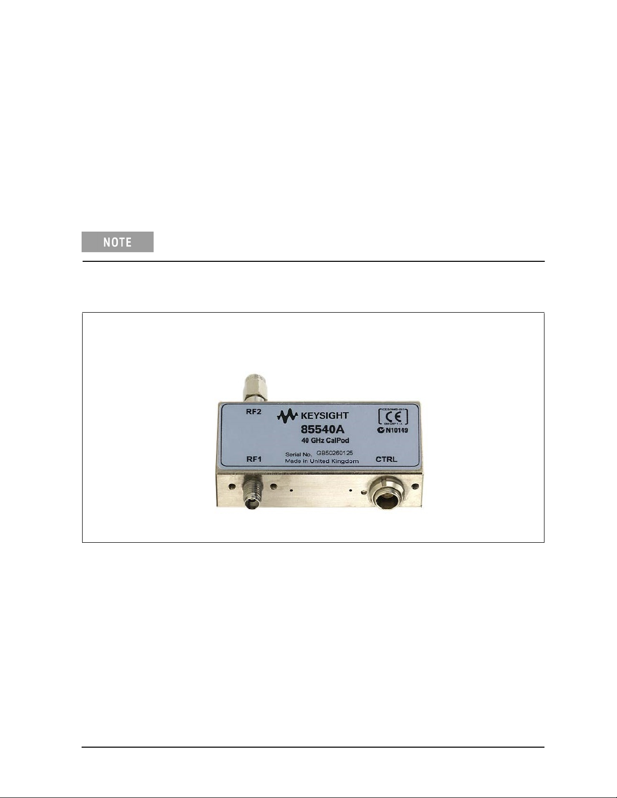
• 85540A 40 GHz CalPod (Standard)
• 85541A 40 GHz CalPod (Temperature Characterized)
• 85542A 40 GHz CalPod (Thermal-Vacuum Environments)
• 85540B 40 GHz CalPod (4-State, 40 GHz Standard)
• 85541B 40 GHz CalPod (4-State, 40 GHz Temperature Characterized)
• 85542B 40 GHz CalPod (4-State, Thermal-Vacuum Environments)
Each 855xxA/B Series CalPod is controlled with the 85523B CalPod Controller.
Chapter Overview (Hyperlinks)
• “Step 1. Inspect the Shipment” on page 1-3
• “Step 2. Meet Electrical and Environmental Requirements” on page 1-7
• “Step 3. Download the CalPod Installation Package” on page 1-7
• “Step 4. Load Temperature Characterization Data” on page 1-11
• “Step 5. Connect the LAN Cable” on page 1-13
• “Step 6. Confirm the Settings on the CalPod Controller” on page 1-14
• “Step 7. Configure the CalPods” on page 1-15
• “Step 8. Configure the Hardware for a Calibration” on page 1-18
• “Step 9. Perform Initial 2-Port Calibration” on page 1-20
• “Step 10. Initialize the CalPods” on page 1-22
• "Step 11. Configure the Hardware for a Measurement" on page 1-22
• "Step 12. Recorrect (Refresh) the CalPods" on page 1-22
• "Step 13. Measure the DUT" on page 1-23
1-2 User’s Guide 85523-90005
Page 9
855xxA/B Series CalPods and 85523B CalPod Controller Usage Information
Step 1. Inspect the Shipment
1.1 Unpack the contents of the shipping container. Keep the container and packaging material in case
the contents needs to be returned to the factory.
1.2. Use the Contents List in the shipping container to verify the completeness of your shipment. If not
complete, refer to “Contacting Keysight” on page 3-2.
1.3. Carefully inspect each item in your shipment to make sure it was not damaged during shipment. If
damaged, refer to “Contacting Keysight” on page 3-2.
The following pages list items that may be included in your shipment, depending
on what you purchased. Your shipment may not contain all items shown.
Table 1-1 Shipment Items
85530B 100 MHz to 20 GHz CalPod (Standard)1, or
85540A/B 500 MHz to 40 GHz CalPod (Standard)
1, 2
RF2 Connector
2.92 mm (m)
RF1 Connector
2.92 mm (f)
CTRL Connector
9 Pin
User’s Guide 85523-90005 1-3
Page 10

855xxA/B Series CalPods and 85523B CalPod ControllerUsage Information
Table 1-1 Shipment Items
85531B 100 MHz to 20 GHz CalPod (Temperature Characterized)1, or
85541A/B 500 MHz to 40 GHz CalPod (Temperature Characterized)
As shown in the graphic below, each temperature characterized CalPod comes with
a USB drive that has a matching serial number. Each USB drive contains
temperature characterization data that is unique to each 85531B 20 GHz CalPod or
85541A 40 GHz CalPod.
1, 2
CalPod
USB Drive
85532B 100 MHz to 20 GHz CalPod (Thermal-Vacuum Environments)1, or
,
85542A/B 500 MHz to 40 GHz CalPod (Thermal-Vacuum Environments)
Photos of the 85532B 20 GHz CalPod and the 85542A 40 GHz CalPod are not available. However,
these CalPod models look the same as the 85531A 20 GHz CalPod shown above, except for the label.
85523B CalPod Controller
0960-2955 USB 2.0 to LAN Adapter, 7.5 inch
1
3
1
2
1-4 User’s Guide 85523-90005
Page 11

855xxA/B Series CalPods and 85523B CalPod Controller Usage Information
Table 1-1 Shipment Items
85553A CalPod Drive Cable (2 meter, 28 AWG) included with:
• 85530B 20 GHz CalPod (Standard)
• 85531B 20 GHz CalPod (Temperature Characterized)
• 85532B 20 GHz CalPod (Thermal-Vacuum Environments)
• 85540A/B 40 GHz CalPod (Standard)
• 85541A/B 40 GHz CalPod (Temperature Characterized)
• 85542A/B 40 GHz CalPod (Thermal-Vacuum Environments)
CalPod drive cables vary, depending on the CalPod model. The cables have
connector alignment keys that allow only the proper cable to connect to the
appropriate CalPod. This ensures that no mistake is made when connecting the
drive cable to the CalPod.
A CalPod drive cable with two alignment k
85530/31/32B
CalPods.
alignment key (shown below).
The older
GHz
20
CalPods
85530/31/32A
as
well
CalPods
as
eys (shown below)
85540/41/42 A and B,
the
the
use
drive
cable
is
with
used
with the
40 GHz
only one
User’s Guide 85523-90005 1-5
Page 12

855xxA/B Series CalPods and 85523B CalPod ControllerUsage Information
Table 1-1 Shipment Items
85554A 20 GHz and 40 GHz CalPod Drive Cable Extension4 (10 meter, 22 AWG)
85555A Splitter Drive Cable (2 meter, 22 AWG) included with 85556A 1x12 Fan-Out Cable Splitter
85556A 1x12 Fan-Out Cable Splitter
The 85556A 1x12 fan-out cable splitter is used to drive up to 12 CalPods from a single port on the
85523B CalPod controller.
For information on connecting more than four CalPods in a measurement hardware configuration, refer
to “Configuration: Using a 1 x 12 CalPod Cable Fan-Out Splitter for More Than Four CalPods”
on page 2-7.
1. For CalPod drive cables, see Table 1-1, “Shipment Items,” on page 1-3.
2. Although the 85540A/B, 85541A/B, and the 85542A/B 40 GHz CalPods are only characterized
from 500 MHz to 40 GHz, they can function from 100 MHz to 40 GHz.
3. The device driver software for the USB 2.0 to LAN Adapter is installed during the procedure
“Step 3. Download the CalPod Installation Package” on page 1-7
4. CalPod drive cable extensions may be used with either the 85552A 20 GHz CalPod drive cable
or the 85553A 40 GHz CalPod drive cable.
1-6 User’s Guide 85523-90005
Page 13

855xxA/B Series CalPods and 85523B CalPod Controller Usage Information
Step 2. Meet Electrical and Environmental Requirements
This instrument has autoranging line voltage input. Be sure the supply voltage
is within the specified range.
2.1 Ensure the available AC power source meets the following requirements:
• Frequency
❏ 50/60 Hz
• Voltage
❏ 100/120/220/240 VAC
The instrument can operate with mains supply voltage fluctuations up to +/10% of the nominal voltage.
• Power (maximum consumed)
❏ 350 W
2.2 Ensure the operating environment meets the requirements found in “Environmental Information” on
page 3-9.
2.3. Verify that the AC power cable is not damaged, and that the power-source outlet provides a
protective earth contact.
Use the Keysight supplied power cord or one with the same or better electrical
rating. Failure to ensure adequate earth grounding by not using this cord may
cause personal injury or product damage.
Step 3. Download the CalPod Installation Package for Windows XP and Win7 OS
Step 3 assumes that the CalPod Installation Package has not previously
been installed on the PNA.
The CalPod Installation Package is a software package that includes all software required for full
CalPod operation. It is compatible with PNA firmware (application code) version A.09.33.05 or
later. If you have an old version of PNA firmware, go to http://na.support.keysight.com/pna/
firmware and download the latest version.
3.1 On the PNA, select File > Minimize Application.
3.2 Connect a LAN cable to the PNA for access to the Internet.
3.3 Select Start > Programs > Internet Explorer.
3.4 Navigate to the 855xxA/B Series CalPod website at: http://na.support.keysight.com/calpod/
3.5 Scroll down the Web page and click the link titled: CalPod Software Installation.
3.6 Select the download according to the PNA Windows OS. At the prompt (“This File Download Security Warning”), select Save (do not select Run) to save the file to the PNA.
User’s Guide 85523-90005 1-7
Page 14

855xxA/B Series CalPods and 85523B CalPod ControllerUsage Information
3.7 When the download is complete, click Run and follow the prompts. At the end of the installation,
click Close and the software is ready to use.
For Windows 7, skip Steps 3.8 through 3.12 and continue to Step 3.13.
For Windows XP, continue with Steps 3.8 through 3.13.
3.8 Select 1. Install the USB-to-LAN adapter driver.
At the end of the installation process, a screen is displayed that allows the driver software for the
USB 2.0 to LAN adapter to be installed.
3.9 Press any key to continue at the information window.
3.10 Select 39998-USB 2.0 to Fast Ethernet Adapter from the list.
1-8 User’s Guide 85523-90005
Page 15

855xxA/B Series CalPods and 85523B CalPod Controller Usage Information
3.11 Select Install Software - Windows XP and 2000 from the list.
If there is a prompt to completely remove the selected application, perform the following:
1. Click Yes
2. At the next dialog window, wait for approximately five seconds before clicking Finish
.
.
3. Repeat Step 3.11 to reinstall the driver application.
3.12 Wait for an Install Shield Wizard screen with a “Finish” button. When it appears, select Finish.
3.13 Enable the CalPod firmware license (option 301 or 302).
This step (Step 3.13) only applies to a network analyzer with firmware version
A.09.xx.xx or older. Version A.10.49.11 or higher does not require enabling
option 301 or 302.
To use the CalPod Installation Package that was downloaded in “Step 3. Download the CalPod
Installation Package for Windows XP and Win7 OS” on page 1-7, the CalPod firmware license
option (301 or 302) has to be enabled using a keyword that is specific for your PNA model and
serial number. This keyword was sent to you by Keysight. Use the following instructions to enter
the keyword in the PNA using the PNA front panel HARDKEYs and [softkeys].
1. On the PNA, press SYSTEM > [Service] > [Option Enable].
2. In the Option Enable dialog box, use the pull-down menu to select the CalPod firmware
option you bought with your initial purchase. If you don’t know which option was purchased,
refer to the papers in the shipment container.
3. Enter the keyword.
4. Select Permanent > Enable.
5. Click Yes to restart the PNA and enable the new firmware.
User’s Guide 85523-90005 1-9
Page 16

855xxA/B Series CalPods and 85523B CalPod ControllerUsage Information
6. Confirm the PNA Model, Firmware Revision, and Installed Options.
a. If not already active, start the PNA application.
b. Select the Help pull-down menu.
c. Select About Network Analyzer and note the following:
1. PNA model.
2. PNA firmware (application code) version.
3. PNA option 301 or 302 is installed.
d. Compare the information you just noted with the information in Table 1-2. If your PNA is
not compatible with your CalPods, or if Option 301 or 302 is not installed, contact Keysight.
Refer to “Contacting Keysight” on page 3-2. If you have an old version of PNA firmware, go
to http://na.support.keysight.com/pna/firmware and download the latest version.
e. Select OK.
f. Select the File pull down menu and select Minimize Application.
Table 1-2 PNA Models, Firmware, Firmware Options Required for 855xxA/B Series CalPods
PNA Models PNA Firmware
Version
N524xA PNA-X
N522xA PNA 85540A 40 GHz CalPod
N523xA
N5230C PNA-L 85532B 20 GHz CalPod
E836xC PNA A.09.85.07
PNA-L
A.09.33.05
or later
or earlier
PNA Options (CalPod
Firmware License)
Option 301
Option 302
855xxA/B CalPod Modules
85530B 20 GHz CalPod
85531B 20 GHz CalPod
85541A 40 GHz CalPod
85542A 40 GHz CalPod
1-10 User’s Guide 85523-90005
Page 17

855xxA/B Series CalPods and 85523B CalPod Controller Usage Information
PNA Options for CalPod Firmware
PNA firmware option 301 is used for ambient temperature operation of CalPods and provides
accurate recorrection capabilities over the temperature range +20 to +30 °C. A maximum of only
four CalPods can be controlled with option 301. The temperature compensated and thermalvacuum environment CalPods can be used with firmware option 301, but they will not have
temperature compensation capabilities.
PNA firmware option 302 is used for temperature compensated and thermal-vacuum CalPods,
and provides accurate recorrection capabilities over the temperature range –30 to +80 °C. With
firmware option 302, up to 48 CalPods can be controlled, but only four CalPods at a time can be
recorrected.
Step 4. Load Temperature Characterization Data
The following process is required for 85531B, 85532B, 85541A, and 85542A Cal
Pods. It is not required for an 85530B or 85540A CalPod since these models do
not have Temperature Characterization data.
If your CalPod model is an 85531B, 85532B, 85541A/B, or 85542A/B, it is temperature compensated,
and was shipped with a USB drive that has a matching serial number – refer to Figure 1-1., “USB
Drive Matches Serial Number on CalPod,” on page 1-12. The USB drive contains Temperature
Characterization data that must be loaded into the PNA. To do so, use the following procedure.
4.1 Insert the USB drive into any USB port on the PNA.
4.2 To access the Windows desktop when the PNA application is active, select File > Minimize
Appli
cation.
4.3. Right-click on Start and select Explore.
4.4 Navigate to the files on the USB drive, and double-click setup.exe to run the program.
4.5 In the dialog window titled “CalPod Thermal Characterization Data Install Utility,” click
“I accept license terms...” and wait for additional text to be displayed. This loads CalPod
Temperature Characterization data in the PNA.
4.6 When “PNA restore archive complete” is displayed at the bottom of the window, close the
window.
4.7 Remove the USB drive from the PNA.
4.8 Repeat “Step 4. Load Temperature Characterization Data” on this page for each CalPod to
be used with the PNA.
User’s Guide 85523-90005 1-11
Page 18

855xxA/B Series CalPods and 85523B CalPod ControllerUsage Information
Figure 1-1 USB Drive Matches Serial Number on CalPod
Serial Number on USB Drive
(ignore preceding letters)
Serial Number on CalPod
(ignore preceding letters)
1-12 User’s Guide 85523-90005
Page 19
855xxA/B Series CalPods and 85523B CalPod Controller
Usage Information
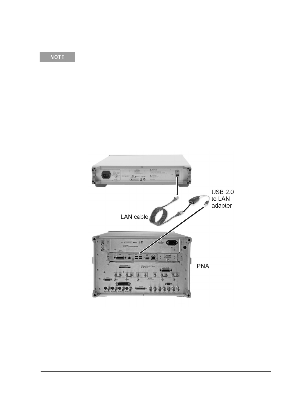
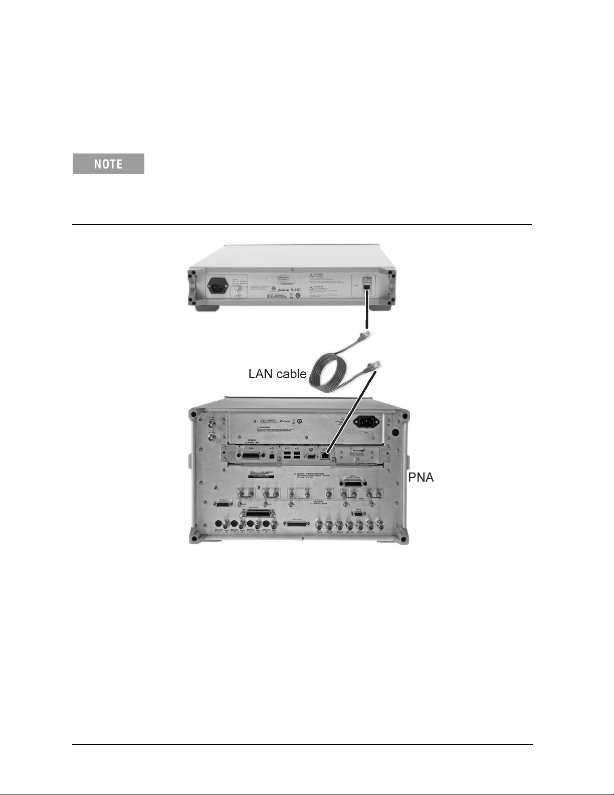
Step 5. Connect the LAN Cable
A LAN cable is required, but is not included. Either a standard or cross-over LAN
cable can be used. (A cross-over LAN cable is used to connect computing devices
together directly where they would normally be connected via a network switch,
hub, or router.)
• The following graphic shows the recommended configuration for the LAN cable. Information
on an alternative configuration can be found at “Alternative Configuration for the LAN Cable
(Not Recommended)” on page 2-4. Although this alternative is not recommended, it can be
used when the USB 2.0 to LAN adapter is not available.
• 85523B CalPod Controllers do not support DHCP networking.
• The 85523B CalPod Controller is set to a static IP Address (default: 192.168.0.100.)
• For additional information on making connections to the LAN using network switches and
network hubs, contact your network administrator.
5.1 As shown in the graphic above, connect a LAN cable (not included) to the rear of the 85523B
CalPod Controller and connect the other end to the USB 2.0 to LAN adapter (part number
0960-2955).
5.2 As shown in the graphic above, connect the USB 2.0 to LAN adapter to a USB port on the PNA.
(Typically this is on the rear of the PNA, but any USB port can be used.)
5.3 Verify that AC line cords are connected to both the PNA and CalPod Controller and that they
are powered on.
User’s Guide 85523-90005 1-13
Page 20

855xxA/B Series CalPods and 85523B CalPod ControllerUsage Information
5.4 Select File > Minimize Application.
5.5 Run the CalPod LAN Config icon on the PNA desktop and select 2. USB-to-LAN-Adapter.
5.6 Follow the remaining prompts.
Step 6. Confirm the Settings on the CalPod Controller
Use either of the following methods to run the IP setup utility and confirm the default settings
shown in the table below.
Method 1: Using the PNA front panel HARDKEYs and [softkeys].
• On the PNA, press CAL > [More] > [CalPod] > [CalPod].
• On the dialog window titled “Calibration Module Refresh Configuration,” click [CalPod Setup].
• On the dialog window titled “CalPod Setup,” click [IP Setup].
Method 2: Using the mouse and the PNA pull-down menus.
• On the PNA, click Start > Programs > CalPod > API > IP Setup.
If the default settings are not correctly displayed, use the keypad to enter them in the IP Setup
dialog window.
The default addresses for the 85523B CalPod Controller are shown in the following table.
Setting Default Address
IP 192.168.0.100
Network mask 255.255.255.0
Gateway 192.168.0.1
DNS
0.0.0.0
(or leave blank)
For additional information on making connections to the LAN using network switches and
network hubs, contact your network administrator.
1-14 User’s Guide 85523-90005
Page 21
855xxA/B Series CalPods and 85523B CalPod Controller Usage Information
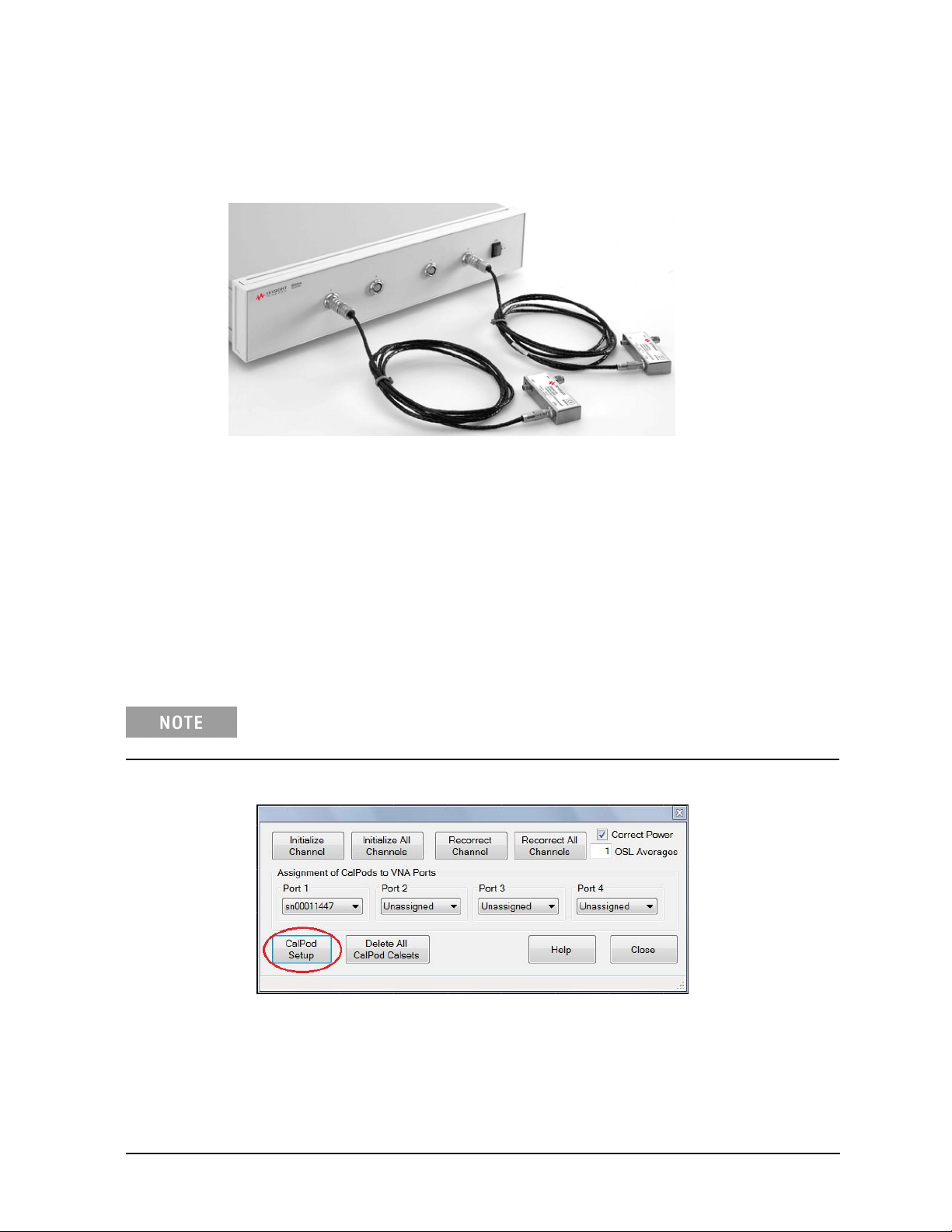
Step 7. Configure the CalPods
7.1 Connect each CalPod to the CalPod controller, as shown in the following graphic.
For CalPod drive cables, see “Step 1. Inspect the Shipment” on page 1-3.
7.2 If not already active, start the PNA application.
7.3 Start the CalPod dialog window titled 'Calibration Refresh Module Configuration" using
either method below.
Method 1: Using the PNA front panel HARDKEYS and [softkeys].
Press CAL > [More] > [Calpod] > [Calpod]
Method 2: Using the mouse and the PNA pull-down menus.
Click Response > Cal > Calpod > Calpod
If a “Windows Security Alert” appears that is related to the etrak Api, select
“Unblock.”
7.4 Select CalPod Setup on the Calibration Refresh Module Configuration window.
7.5 If using thermal CalPods, the serial numbers will automatically appear in the CalPod Setup dialog
window. However, if using standard CalPods, enter a CalPod serial number, omitting preceding
letters, the click Add CalPod.
User’s Guide 85523-90005 1-15
Page 22
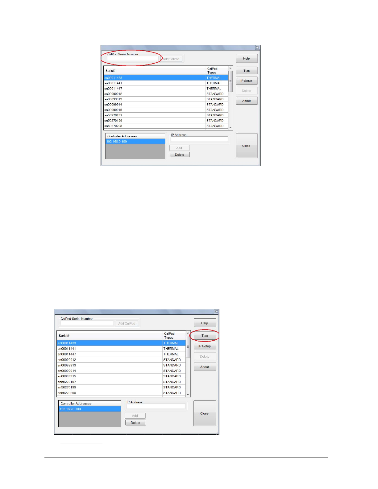
Enter serial number
In the dialog window column “CalPod Types:”
855xxA/B Series CalPods and 85523B CalPod ControllerUsage Information
• “STANDARD” refers to the 85530B 20 GHz CalPod and 85540A/B 40 GHz CalPod, and requires
software Option 301 or 302. The list is limited to four entries when Option 301 is the only option
1
1
installed.
• “THERMAL” refers to the 85531/32B 20 GHz CalPod and 85541/42A and B 40 GHz CalPod, and
requires software Option 302. More than four entries can be listed with Option 302.
1
1
In order for a CalPod to be listed as “THERMAL,” its Temperature Characterization data must have been
installed previously in “Step 4. Load Temperature Characterization Data” on page 1-11. Without its
Temperature Characterization data loaded, each CalPod will be listed as a “STANDARD.”
7. Repeat the previous step for each standard CalPod you are using with the PNA.
7.7 Using the CalPod Setup Dialog window, highlight a CalPod serial number and click est.
The dialog windows displays a list of one or more CalPod serial numbers.
Highlight the serial number and select Test
1. Applies to firmware version A.09.33.xx or earlier.
1-16 User’s Guide 85523-90005
Page 23
855xxA/B Series CalPods and 85523B CalPod Controller Usage Information
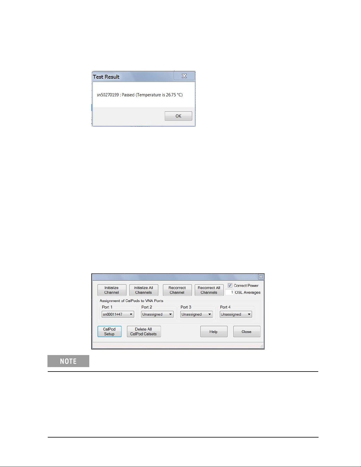
• If the Test Result dialog window shows “Passed,” the CalPod is functioning. The temperature
displayed is the internal temperature of the CalPod microcircuit.
If Test Result shows "Failed" and the window text contains the words “Controller @ .... :Failed”
•
— Check that the CalPod Controller is powered on and connected to the PNA correctly. See
“Step 5. Connect the LAN Cable” on page 1-13.
— If all connections appear to be correct and the USB 2.0 to LAN Adapter is being used, set a
static IP address on the PNA. See "Setting a Static IP Address on the PNA (When Using USB
2.0 to LAN Adapter)" on page 2-3.
If Test Result shows "Failed" and the window text contains the words “sn .... :Failed,” check that
•
the CalPod is properly connected to the CalPod Controller.
7.8 After each CalPod serial number has been highlighted and tested, click Close to return to
the “Calibration Refresh Module Configuration” dialog menu.
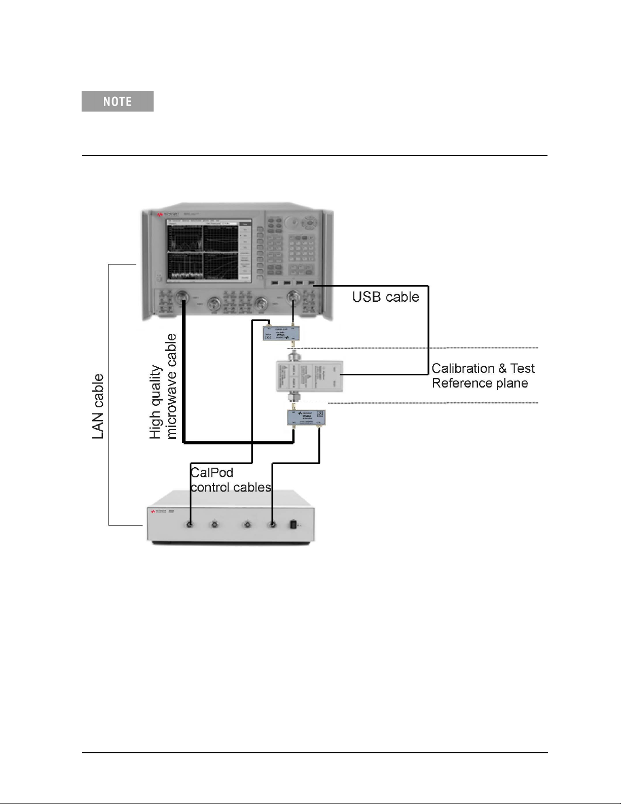
7.9 Assign each CalPod to a PNA test port.
1. In the “Calibration Refresh Module Configuration” dialog window shown below, under
the heading “Assignment of CalPods to VNA Ports,” assign a CalPod to each test port
on the PNA. Note that Port 1, Port 2, Port 3, and Port 4 refer to the PNA test ports,
and not the connector labels on the 85523B CalPod controller.
Clicking Help in the dialog window displays CalPod information in the PNA
Series Network Analyzer Help System, stored in the PNA.
As indicated in the example above, CalPod serial number 00011447 has been assigned
to PNA test Port 1.
2. After each CalPod has been assigned to a test port on the PNA, click Close.
User’s Guide 85523-90005 1-17
Page 24

855xxA/B Series CalPods and 85523B CalPod ControllerUsage Information
Step 8. Configure the Hardware for a Calibration
Figure 1-2, “Basic Measurement Hardware Configuration for Calibration (2-Port DUT),” on page 1-19
shows a recommended, basic measurement hardware configuration for calibrating the PNA when
measuring a 2-port DUT. For information on more complex configurations, see the 855xxA/B Series
CalPod Information website at: http://na.support.keysight.com/calpod.
The following items may be required, depending on your measurement hardware configuration.
• RF Cables – required to connect each CalPod to a PNA port. CalPods work well with cable losses
(one- way loss from CalPod to PNA test port) up to 20 dB. CalPods will also work with cable
losses greater than 20 dB, but the recorrection performance may be degraded. Consult the
855xxA/B Series CalPod Performance Characteristics document (85523-90007) available at:
http://na.support.keysight.com/calpod/calpod_pc_85523-90007.pdf
• RF Adapters for the Device Under Test (DUT) – required if
the DUT connectors are not compatible
with the CalPod RF2 (2.92 mm male) connector.
• Calibration Kit or ECal – compatible with DUT connectors.
• (Optional) CalPod Drive Cable Extensions – The standard CalPod drive cable is 2 meters in length.
The 85554A CalPod drive cable extension provides an additional 10 meter length. These CalPod
drive cable extensions can be cascaded.
1-18 User’s Guide 85523-90005
Page 25
855xxA/B Series CalPods and 85523B CalPod Controller Usage Information
Figure 1-2 shows an ECal module with 3.5 mm f-f connectors. If using an ECal module
with 3.5 mm m-f connectors, the female connector on the ECal module must be
connected to each CalPod one-at-a-time. Follow the guided ECal calibration procedure
on the PNA. Avoid using adaptors between the ECal module and the CalPod connectors,
if possible.
Figure 1-2 Basic Measurement Hardware Configuration for Calibration (2-Port DUT)
User’s Guide 85523-90005 1-19
Page 26

Usage Information
855xxA/B Series CalPods and 85523B CalPod Controller
Step 9. Perform Initial 2-Port Calibration
Information
• The instructions in this step assume that CalPods are connected to PNA Port 1 and Port 2, and that a
2-Port calibration is used.
• Most PNA calibration types may be used with CalPods. For details, see “Calibration Types Not Supported
by CalPods” on page 2-3.
• For information on PNA traces and channels, see the Quick Start section of the PNA Series Network
Analyzer Help System (available online and stored in the PNA).
• Notes on the calibration:
— An ECal or a mechanical calibration kit may be used to perform the calibration. An ECal is preferred
because the RF cables can remain totally undisturbed during the calibration and initialization steps.
— When an ECal is used and multiple connections are required, order the steps such that the final step
is an ECal “Thru” state connection.
— When a mechanical calibration kit is used, take precautions to minimize cable movement. Leave the
final standards connected during the initialization step in the following procedure.
— When the ECal or calibration kit is a 2.4 mm connector type, use appropriate adapters on the CalPod
RF1 and RF2 connectors (2.92 mm) during calibration.
Procedure
9
.1 Connect the CalPods to the CalPod Controller.
9.2 Power on the CalPod Controller.
9.3 Start the CalPod dialog wind
ow titled "Calibration Refresh Module Configuration" using
either method below.
Method 1:
Method 2:
Using the PNA front panel HARDKEYS and [softkeys].
Press
CAL > [More] > [CalPod] > [CalPod]
Using the mouse and the PNA pull-down menus.
Response > Cal > CalPod > CalPod
Click
If a “Windows Security Alert” appears that is related to the etrak Api, select “Unblock.”
9.4 Assign CalPods to PNA Port 1 and Port 2 or confirm that the appropriate assignments already exist.
Click the down arrow to select from available CalPods for a given port.
It is important to activate the CalPod dialog window at this point to ensure the
CalPods are in the “thru” state.
9.5 Close the CalPod dialog window.
9.6 Configure the measurement hardware for the initial calibration.
The initial calibration consists of performing a normal calibration (typically with an ECal module), and
1-20 User’s Guide 85523-90005
Page 27

855xxA/B Series CalPods and 85523B CalPod Controller Usage Information
then transferring this correction array to the CalPods when the Initialize Channel command is
performed in Step 9.8.
The configuration for the initial ECal calibration and CalPod channel initialization can be
significantly different from the final measurement configuration. A short cable between the PNA
test port and the CalPod – as shown in the following graphic – can be used for the initial
calibration. For the measurement, an entirely different cable with greater length and higher loss
can be substituted between the PNA test ports and the CalPods. Additionally, different adapters,
and even switch matrices can be added after the initial calibration to enable a measurement
configuration.
9.7 Setup the measurement parameters on the PNA.
• Preset the PNA.
• Set up a 2-port measurement channel with the desired parameters for your DUT, including:
— class (choose from S-parameters, source power cal and receiver power calibrations, scalar
and vector mixer measurements, gain compression for amplifiers and mixers, noise figure for
amplifiers and mixers, noise figure for amplifiers or mixers, IMD measurements for amplifiers
or mixers, IMD spectrum mode)
— start and stop frequencies (20 GHz CalPods are characterized from 100 MHz to 20 GHz;
40 GHz CalPods are characterized from 500 MHz to 40 GHz).
— number of points
For best initial calibration results, use a 1 kHz or lower IF bandwidth with an
averaging factor of eight. Sweep averaging is recommended. For the actual DUT
measurements, the IF bandwidth and number of averages can vary.
9.8 Use either of the following methods to perform a full 2-port calibration on the PNA, using an
ECAL module (for highest accuracy) or a mechanical calibration kit.
Method 1: Using the PNA front panel HARDKEYS and [softkeys].
Press Cal > [Start Cal] > [Cal Wizard].
User’s Guide 85523-90005 1-21
Page 28

855xxA/B Series CalPods and 85523B CalPod ControllerUsage Information
Method 2: Using the mouse and the PNA pull-down menus.
Click Response > Cal > Start Cal > Cal Wizard.
• Follow the prompts in the calibration wizard to complete the calibration
• Select Save as User CalSet. Any file name that does not contain “calpod” may be used.
You must select Save as User CalSet (rather than “Finish”) to save the
calibration in the channel 1 cal regist
er.
IMPORTANT
After completing the calibration, do not disturb any of the measurement hardware,
until “Step 10. Initialize the CalPods” is completed, and the Initialize Channel
operation has been performed on the CalPods. During this operation, the CalPods
make a measurement requiring the same measurement hardware to properly
initialize the CalPod correction arrays.
Step 10. Initialize the CalPods
Without disturbing any of the measurement hardware, use either of the following methods to save the
initial calibration into the CalPod correction array. This must be done immediately after completing
the last step of the initial calibration.
Method 1: Using the PNA front panel HARDKEYs and [softkeys].
Press CAL > [More] > [Calpod] > [Initialize Channel]
Method 2: Using the mouse and the PNA pull-down menus.
Click Response > Calpod > Initialize Channel
The calibration correction array established by the initial calibration is transferred to the CalPod
correction array in this step. Any disturbances of the measurement hardware (such as cable
movements) prior to performing the Initialize Channel step will affect the quality of the recorrection
array.
IMPORTANT Do not Initialize Channel at any future point in time or the recorrection array will
be corrupted, causing improper recorrections and inaccurate measurement data.
Step 11. Configure the Hardware for a Measurement
After the Initialize Channel procedure is completed, as detailed in the previous step, the
measurement hardware can be reconfigured. For example, the short, stable cable between PNA
port 1 and the CalPod can be replaced with a longer cable to reach a CalPod and DUT located
inside a temperature or TVAC chamber. Other modifications in the path between the PNA and
the CalPod – such as different adapters, and even switch matrices – can now be made.
Step 12. Recorrect (Refresh) the CalPods
When a calibration refresh is performed, the initial calibration is reestablished at the new
location of the CalPods.
1-22 User’s Guide 85523-90005
Page 29

855xxA/B Series CalPods and 85523B CalPod Controller Usage Information
12.1 Connect the CalPods to the DUT and recorrect the calibration using either of the following methods.
Method 1: Using the PNA front panel HARDKEYs and [softkeys].
Press CAL > [More] > [Calpod] > [Recorrect Channel]
Method 2: Using the mouse and the PNA pull-down menus.
Click Response > Cal > Calpod > Recorrect Channel
The system is now ready to make calibrated measurements on
the DUT.
12.2 When you want to reestablish the initial calibration, refresh the calibration using either of the
methods above. Some examples of situations that call for a calibration refresh:
• Moving the location of the CalPods and DUT. For example, moving them from close
proximity with the PNA to inside a temperature or thermal-vacuum chamber.
• Changing cables, cable lengths, or connectors in the path between the PNA and the
CalPod.
• Adding a switch matrix or adaptors in the path between the PNA and the CalPod.
• Changing switch positions in a switch matrix.
• Changing temperatures inside of a temperature or thermal-vacuum chamber where the
CalPod and DUT are located.
• Moving or flexing the cables.
• Wanting to be certain that a valid calibration is present at the calibration plane.
Step 13: Measure the DUT
Gather data from the PNA measurement of the DUT.
User’s Guide 85523-90005 1-23
Page 30

855xxA/B Series CalPods and 85523B CalPod ControllerUsage Information
1-24 User’s Guide 85523-90005
Page 31

2 Reference Information
2-1
Page 32

855xxA/B Series CalPods and 85523B CalPod ControllerReference Information
Miscellaneous Reference Information
Chapter Overview (Hyperlinks)
• “Websites with Additional PNA Information Related to CalPods” on page 2-2
• “85523B CalPod Controller Dimensions and Weight” on page 2-2
• "85523B CalPod Controller Front Panel Output Connectors" on page 2-3
• “CalPod Operational Check” on page 2-3
• “Calibration Types Not Supported by CalPods” on page 2-3
• “Setting a Static IP Address on
• “Alternative Configuration for the LAN Cable (Not Recommended)” on page 2-4
• “Configuration: Distance Between Controller and CalPod is 2 Meters or Less” on page 2-6
• “Configuration: Distance Between Controller and CalPod is More Than 2 Meters” on page 2-7
• “Configuration: Using a 1 x 12 CalPod Cable Fan-Out Splitter for More Than Four CalPods” on page
2-7
• “Configuration: Distance Between Controller and Splitter is More/Less Than 2 Meters” on page 2-8
• “Configuration: Using as Many as 48 CalPods with One Controller” on page 2-9
• “Configuration: Using as Many as 48 CalPods with One Controller Over a Long Distance” on page
2-10
• “Configuration: Long Distance Between Splitter and CalPod” on page 2-10
• “Configuration: Control Through a TVAC Chamber Wall” on page 2-11
the PNA (When Using USB 2.0 to LAN Adapter)” on page 2-3
Websites with Additional PNA Information Related to CalPods
• Keysight 855xxA/B Series CalPod Information
http://na.support.keysight.com/calpod
• Keysight 855xxA/B Series CalPod Performance Characteristics
http://na.support.keysight.com/pna/calpod/calpod_pc_85523-90007.pdf
• Keysight 855xxA/B Series CalPod Performance Information in PNA Online Help
http://na.support.keysight.com/pna/calpod/calpod_help.htm
• Network Analyzer Firmware
http://na.support.keysight.com/pna/firmware
• General PNA Documentation
http://na.support.keysight.com/pna
85523B Calpod Controller Dimensions and Weight
• Height: 89 mm
• Width: 425 mm
• Depth: 500 mm
• Weight: 7.5 kg
2-2 User’s Guide 85523-90005
Page 33

855xxA/B Series CalPods and 85523B CalPod Controller Reference Information
85523B CalPod Controller Front Panel Output Connectors
• Connector type: LEMO USA ECG.2B.312.CLV (Keysight part number 1254-1449)
• Maximum output: +/- 15 VDC
CalPod Operational Check
A CalPod module may be tested using the CalPod Operational Check. For instructions, refer to
the CalPod portion of PNA Online Help at:
http://na.support.keysight.com/pna/calpod/calpod_help.htm#OpCheck
Calibration Types Not Supported by CalPods
Keysight 855xxA/B Series CalPods support almost all PNA S-parameter calibration types. The
exceptions are calibration types that do not include a return loss portion for the port connected
to the CalPod. An example of an unsupported calibration type is a Response Calibration.
When an unsupported calibration type is used, the CalPod software reports an error during
“Initialize Channel.”
Setting a Static IP Address on the PNA (When Using USB 2.0 to LAN Adapter)
When the CalPod Controller connects to the PNA via the USB 2.0 to LAN adapter, sometimes it
is necessary to manually set a Static IP address on the LAN interface. Multiple installations of
the CalPod Installation Package may require this procedure.
1. Minimize the PNA application to access the desktop.
2. Click Start > Settings > Network Connections.
There should be two or more listings with the name “Local Area ConnectionsN” (where N may be
blank or an arbitrary character).
3. Right-click on the last item in the list and select Properties.
The listing under “Connect using:” should display “ASIX AX88772 USB2.0 to Fast Ethernet.”
If this text is not displayed, click Cancel and try another item in the list until this device is found.
4. In the listing under “This connection uses the following items:”, scroll down the list and highlight
“Internet Protocol (TCP/IP).”
5. Click Properties or double-click the item on the list.
6. Click “Use the following IP address.”
7. Enter IP Address 192.168.0.1 with a Subnet Mask of 255.255.255.0. “Default Gateway” can be left
blank.
8. Leave the DNS settings blank.
9. Click OK as necessary to close the dialog windows. If you are presented with a dialog window about
entering a different IP address, click No.
10.Return to “Step 7. Configure the CalPods” on page 1-15 and follow the steps to test and verify that
each CalPod is working.
User’s Guide 85523-90005 2-3
Page 34
855xxA/B Series CalPods and 85523B CalPod ControllerReference Information
Alternative Configuration for the LAN Cable (Not Recommended)
If the USB 2.0 to LAN adapter is not available, the following LAN cable configuration can be
used. However, this configuration is not recommended because it does not allow the PNA to
communicate over the LAN with instruments other than the controller.
A LAN cable is required but is not included. If your PNA model is an E836xC or
N5230C, the LAN cable required is the cross-over type; for N524xA, see Figure
2-1 on page 2-5. Any LAN cable may be used with all other PNA models. (A
cross-over LAN cable is used to connect computing devices together directly
where they would normally be connected via a network switch, hub, or router.)
1. As shown in the graphic above, connect an appropriate type of LAN cable (not included) to
the rear of the 85523B CalPod Controller.
2. As shown in the graphic above, connect the other end of the LAN cable to the PNA. (There
is
no network connector available for Web access.)
3. Verify that AC line cords are connected to both the PNA and CalPod Controller and that they
are powered on.
4. Select File > Minimize Application.
5. Run the CalPod LAN Config icon on the PNA desktop and select 1. Direct Cable Connect.
(This configures the PNA to a static IP address.)
2-4 User’s Guide 85523-90005
Page 35
855xxA/B Series CalPods and 85523B CalPod Controller Reference Information
6. Follow remaining prompts.
To return to DHCP on the built-in PNA LAN adapter when CalPod operation
is no longer required, run the CalPod LAN Config icon again and select
option 3.
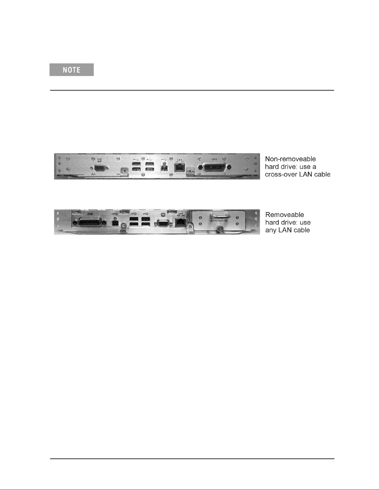
As shown in the following graphic, if your N524xA has a removable hard drive, it can be
connected to the 85523B CalPod Controller with any type of LAN cable. However, if the
N524xA has a non-removable hard drive, it must use a cross-over LAN cable.
Figure 2-1 LAN Cable Requirements for PNA-X N524xA Models
User’s Guide 85523-90005 2-5
Page 36
855xxA/B Series CalPods and 85523B CalPod ControllerReference Information
Advanced Multiport CalPod Configurations
This section provides information on creating multiport CalPod configurations.
Configuration: Distance Between Controller and CalPod is 2 Meters or Less
When the distance between the 85523B CalPod controller and the CalPod unit is two meters or less,
use the 85552A or 82553A CalPod drive cables (included with the CalPods) directly between them.
CalPod drive cables vary, depending on the CalPod model. The cables have connector alignment
keys that allow only the proper cable to connect to the appropriate CalPod. This ensures that no
mistake is made when connecting the drive cable to the CalPod. Refer to page 1-5 for information
on CalPod drive cable compatibility.
2-6 User’s Guide 85523-90005
Page 37

855xxA/B Series CalPods and 85523B CalPod Controller Reference Information
Configuration: Distance Between Controller and CalPod is More Than 2 Meters
When the distance between the 85523B CalPod Controller and the CalPod unit is more than two
meters, an 85554A extension cable for CalPod drive cables is required. This extension cable is 10
meters in length. The 12-pin male connector joins with the 85523B CalPod controller, and the
12-pin female connector joins with the 12-pin connector on the 85552/53A CalPod drive cable (2
meter length). The 9-pin male connector of the 85552/53A CalPod drive cable joins with the
CalPod.
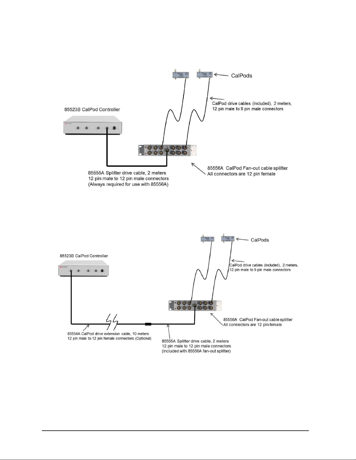
Configuration: Using a 1 x 12 CalPod Cable Fan-Out Splitter for More Than Four
CalPods
As shown in the following graphic, a Keysight 85556A 20 GHz and 40 GHz CalPod 1x12 fan-out
splitter can be used to connect four or more 855xxA/B Series CalPods to an 85523B CalPod
Controller.
User’s Guide 85523-90005 2-7
Page 38
855xxA/B Series CalPods and 85523B CalPod ControllerReference Information
Configuration: Distance Between Controller and Splitter is Less Than 2 Meters
Configuration: Distance Between Controller and Splitter is More Than 2 Meters
When the distance between the controller and the splitter is more than 2 meters, both the
85554A CalPod drive extension cable and the 85555A splitter drive cable are required.
2-8 User’s Guide 85523-90005
Page 39

855xxA/B Series CalPods and 85523B CalPod Controller
Configuration: Using as Many as 48 CalPods with One Controller
Reference Information
As many as 48 CalPods can be controlled by one 85523B CalPod controller. Each of the four
ports on the CalPod controller can drive an 85556A fan-out cable splitter which can each drive
up to 12 CalPods. The drive cable between the 85523B controller and the 85556A splitters
requires either a 2 meter 85555A splitter drive cable, or a combination of an 85554A 10 meter
extension cable with a 2 meter 85555A splitter drive cable, as shown in “Configuration: Using as
Many as 48 CalPods with One Controller Over a Long Distance” on page 2-10. If additional
distance is required, the extension cables can be cascaded.
User’s Guide 85523-90005 2-9
Page 40

855xxA/B Series CalPods and 85523B CalPod ControllerReference Information
Configuration: Using as Many as 48 CalPods with One Controller Over a Long Distance
Configuration: Long Distance Between Splitter and CalPod
When there is a long distance required between the cable splitter and the CalPods, the 85554A
CalPod drive extension cable can be used to provide additional length as shown in the previous
graphic.
2-10 User’s Guide 85523-90005
Page 41

855xxA/B Series CalPods and 85523B CalPod Controller Reference Information
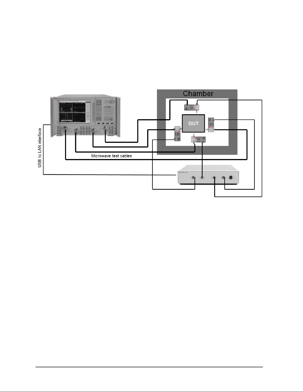
Configuration: Control Through a TVAC Chamber Wall
Thermal-vacuum testing requires controlling the CalPods inside of a TVAC chamber using an
85554A CalPod drive extension cable. This cable is cut to the appropriate length, and the cable
conductors soldered to an appropriate TVAC bulkhead connector to provide DC connections
through the TVAC chamber wall. Alternatively, Pave Technology (www.pavetechnology.com) has
an SP37/13-E-150-15-20-DSUB-DSUB connector that is used for TVAC bulkheads. The control
voltages are +/-15 Vdc with 60 mA per cable conductor.
User’s Guide 85523-90005 2-11
Page 42

855xxA/B Series CalPods and 85523B CalPod ControllerReference Information
2-12 User’s Guide 85523-90005
Page 43

3 Safety and Regulatory Information
Page 44

855xxA/B Series CalPods and 85523B CalPod ControllerSafety and Regulatory Information
Contacting Keysight
Assistance with test and measurements needs and information on finding a local Keysight office
are available on the Web at: www.keysight.com/find/assist
If you do not have access to the Internet, please contact your Keysight field engineer.
In any correspondence or telephone conversation, refer to the Keysight product
by its model number and full serial number. With this information, the Keysight
representative can determine whether your product is still within its warranty
period.
Maintenance
To remove dirt or dust from the external case of the Keysight products, clean the case using a
dry or slightly-dampened cloth only.
If alcohol is used to clean the connectors, the power cord to the instrument must be removed.
All cleaning should take place in a well ventilated area. Allow adequate time for the fumes to
disperse and moist alcohol to evaporate prior to energizing the instrument.
To prevent electrical shock, disconnect instrument from mains before cleaning.
Use a dry cloth or one slightly dampened with water to clean the external case
parts. Do not attempt to clean internally.
Keep isopropyl alcohol away from heat, sparks, and flame. Store in a tightly
closed container. It is extremely flammable. In case of fire, use alcohol foam,
dry chemical, or carbon dioxide; water may be ineffective.
Shipment for Service
Contact Keysight Technologies for instructions on where to ship the Keysight products for
service. Refer to “Contacting Keysight” above.
Ship the Keysight products using the original packaging materials. Shipping the Keysight
products in anything other than the original packaging may result in non-warrantied damage.
If returning a Keysight product for repair, attach a complete description of failure symptoms.
3-2 User’s Guide 85523-90005
Page 45

855xxA/B Series CalPods and 85523B CalPod Controller
Safety and Regulatory Information
Safety Symbols
The following safety symbols are used throughout this manual. Familiarize yourself with each of
the symbols and its meaning before operating this instrument.
Caution denotes a hazard. It calls attention to a procedure that, if not correctly
performed or adhered to, would result in damage to or destruction of the product.
Do not proceed beyond a caution note until the indicated conditions are fully
understood and met.
Warning denotes a hazard. It calls attention to a procedure which, if not
correctly performed or adhered to, could result in injury or loss of life. Do not
proceed beyond a warning note until the indicated conditions are fully
understood and met.
User’s Guide 85523-90005 3-3
Page 46

General Safety Considerations
Safety Earth Ground
The Mains wiring and connectors shall be compatible with the connector used in
the premise electrical system. Failure to ensure adequate earth grounding by not
using the correct components may cause product damage and serious injury.
Before Applying Power
If this product is not used as specified, the protection provided by the equipment
could be impaired. This product must be used in a normal condition (in which all
means for protection are intact) only.
This instrument has autoranging line voltage input. Be sure the supply voltage is
within the specified range.
855xxA/B Series CalPods and 85523B CalPod ControllerSafety and Regulatory Information
Servicing
This product is designed for use in Installation Category II and Pollution
Degree 2 per IEC standards.
Ventilation Requirements: When installing the instrument into a cabinet,
consideration shall be given to the convection flow into and out of the cabinet.
Consideration shall also be given to the individual instruments to avoid having
the heated discharge of one instrument become the cooling intake air for another
instrument. Another area of concern is verification that the maximum ambient
operating temperature of the instrument is not exceeded due to cabinet
installation. Keysight recommends forced air convection whenever an instrument
is installed in a cabinet and further recommends that the maximum operating
temperature of the cabinet be reduced 10 °C lower than the maximum operating
temperature of a single instrument. If there are any concerns or special
requirements, a Keysight Field Engineer should be consulted to assure
instrument temperature compliance and performance.
These servicing instructions are for use by qualified personnel only. To avoid
electrical shock, do not perform any servicing unless you are qualified to do so.
No operator serviceable parts inside. Refer servicing to qualified personnel. To
prevent electrical shock, do not remove covers.
The opening of covers or removal of parts may expose dangerous voltages.
Disconnect the instrument from all voltage sources while it is being opened.
3-4 User’s Guide 85523-90005
Page 47

855xxA/B Series CalPods and 85523B CalPod Controller
The main power cord can be used as the system disconnecting device. It
disconnects the mains circuits from the mains supply.
This is a Safety Class 1 Product (provided with a protective earthing ground
incorporated in the power cord). The mains plug shall only be inserted in a
socket outlet provided with a protective earth contact. Any interruption of the
protective conductor inside or outside of the product is likely to make the
product dangerous. Intentional interruption is prohibited.
For continued protection against fire hazard, replace line fuse only with same
type and rating: Fuse 5A/250V, Part Number 2110-0709. The use of other
fuses, circuit breakers or materials is prohibited.
Safety and Regulatory Information
User’s Guide 85523-90005 3-5
Page 48

855xxA/B Series CalPods and 85523B CalPod ControllerSafety and Regulatory Information
Regulatory Information
This section contains information that is required by various government regulatory agencies.
Instructions for Use
This product has been designed and tested in accordance with accepted industry standards,
and has been supplied in a safe condition. The documentation contains information and
warnings that must be followed by the user to ensure safe operation and to maintain the
product in a safe condition.
Install the instrument so that the detachable power cord is readily identifiable and is easily
reached by the operator.
The detachable power cord is the instrument disconnecting device. It disconnects the mains
circuits from the mains supply before other parts of the instrument. The front panel switch is
only a standby and ON switch and is not a LINE switch (disconnecting device.
Alternatively, an externally installed switch or circuit breaker (which is readily identifiable and is
easily reached by the operator may be used as a disconnecting device.
3-6 User’s Guide 85523-90005
Page 49
855xxA/B Series CalPods and 85523B CalPod Controller
Instrument Markings
Safety and Regulatory Information
Listed below are definitions
ccr.keysight@keysight.com
for the markings that may be found on the product.
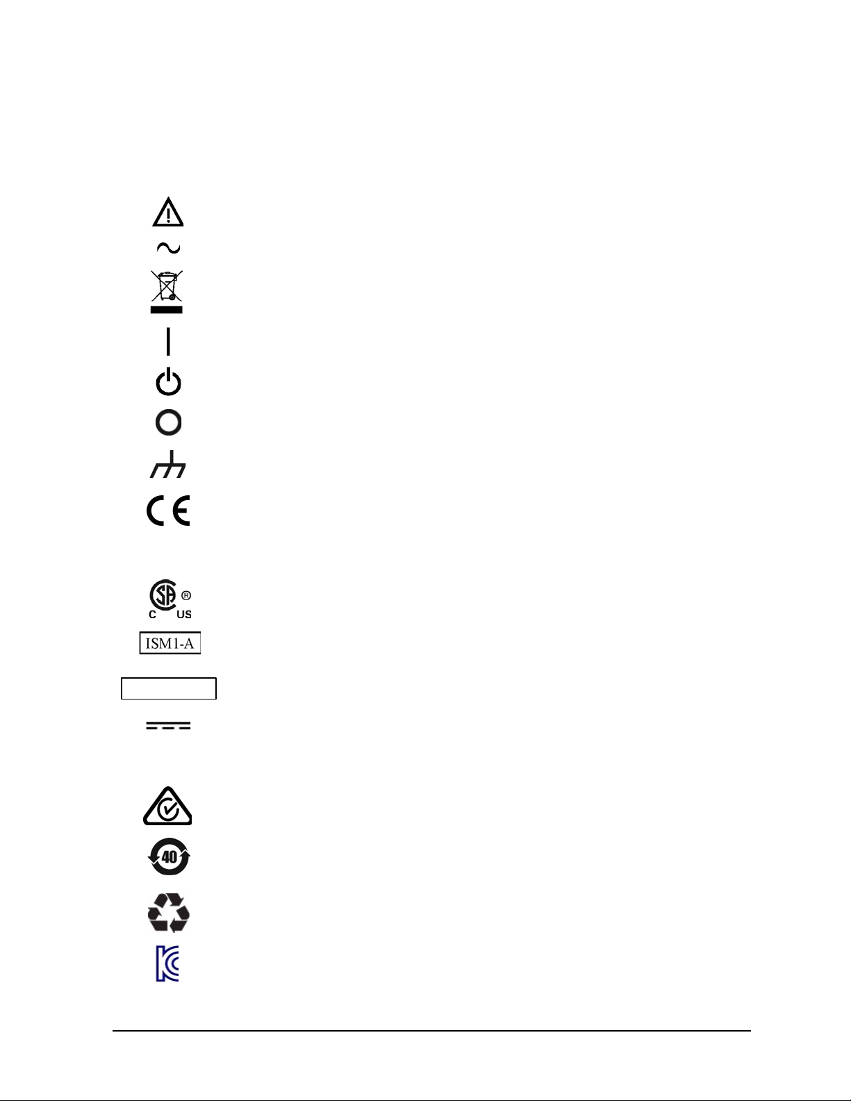
The instruction documentation symbol. The product is marked with this symbol when it is
necessary for the user to refer to the instructions in the documentation.
The AC symbol indicates the required nature of the line module input power.
This symbol indicates separate collection for electrical and electronic equipment,
mandated under EU law. All electric and electronic equipment are required to be separated
from normal waste for disposal (Reference WEEE Directive).
This symbol indicates that the power line switch is ON.
This symbol indicates that the power line switch is in the STANDBY position.
This symbol indicates that the power line switch is in the OFF position.
This symbol is used to identify a terminal which is internally connected to the product frame or
chas
sis.
The CE mark is a registered trademark of the European Community.
The Keysight email address is required by EU directives applicable to our product.
ICES/NMB-001
IP 2 0
The CSA mark is a registered trademark of the CSA International.
This is a symbol of an Industrial Scientific and Medical Group 1 Class A product (CISPR 11,
Clause 5).
This is a marking to indicate product compliance with the Canadian Interference-Causing
Equipment Standard (ICES-001). Cet appareil ISM est conforme à la norme NMB du Canada.
Direct Current.
The instrument has been designed to meet the requirements of IP 2 0 for egress and
operational environment.
The RCM mark is a registered trademark of the Australian Communications and Media
Authority.
Indicates the time period during which no hazardous or toxic substance elements are
expected to leak or deteriorate during normal use. Forty years is the expected useful life of
the product.
This symbol on all primary and secondary packaging indicates compliance to China standard
GB 18455-2001.
South Korean Certification (KC) mark; includes the marking's identifier code which follows the
format: MSIP-REM-YYY-ZZZZZZZ
ZZZZZZZ.
User’s Guide 85523-90005 3-7
Page 50
855xxA/B Series CalPods and 85523B CalPod ControllerSafety and Regulatory Information
Compliance Notices
This product has been designated and tested in accordance with accepted industry standards, and
has been supplied in a safe condition. The documentation contains information and warnings that
must be followed by the user to ensure safe operation and to maintain the product in a safe
condition.
EMC and Safety Information
EMC
Complies with the essential requirements of the European EMC Directive as well as current editions
of the following standards (dates and editions are cited in the Declaration of Conformity):
• IEC/EN 61326-1
• CISPR Pub 11 Group 1, class A
• AS/NZS CISPR 11
• ICES/NMB-001
This ISM device complies with Canadian ICES-001.
Cet appareil ISM est conforme a la norme NMB-001 du Canada.000
South Korean Class A EMC Declaration
Information to the user:
This equipment has been conformity assessed for use in business environments. In a residential
environment, this equipment may cause radio interference.
※ This EMC statement applies to the equipment only for use in a business environment.
사 용 자 안 내 문
이 기기는 업무용 환경에서 사용할 목적으로 적합성평가를 받은 기기로서
가정용 환경에서 사용하는 경우 전파간섭의 우려가 있습니다.
※ 사용자 안내문은 “업무용 방송통신기자재”에만 적용한다.
Safety Information
European Low Voltage Directive is not applicable for these products.
Declaration of Conformity
A declaration of conformity for any of these ECal modules is available at
http://www.keysight.com/go/conformity or by contacting Keysight - see “Contacting Keysight”
on page 3-2.
3-8 User’s Guide 85523-90005
Page 51

855xxA/B Series CalPods and 85523B CalPod Controller
Environmental Information
Table 3-1 Environmental Information
Safety and Regulatory Information
Parameter
Temperature
Operating
Storage
Altitude (Operating)
Relative Humidity Type tested, 0% to 95% at 40 °C, non-condensing
Required Values/Ranges
For Indoor Use ONLY
0 °C to +55 °C
-40 °C to +70 °C
0 to 3,000 meters
Warranty
The actual warranty on your instrument depends on the date it was ordered as well as whether
or not any warranty options were purchased at that time. To determine the exact warranty on
your instrument, contact Keysight Technologies with the model and serial number of your
instrument. Refer to “Contacting Keysight” on page 3-2.
User’s Guide 85523-90005 3-9
Page 52

This information is subject to change without
notice. © Keysight Technologies 2015, 2018
Edition 4, May 2018
Supersedes: July 2017
www.keysight.com
 Loading...