


Keysight 8494/95/96G/H
Attenuators
Operating and
Service Manual

Notices
CAUTION
WARNING
Copyright Notice
© Keysight Technologies 2014 - 2019
No part of this manual may be repro-
duced in any form or by any means
(including electronic storage and
retrieval or translation into a foreign
language) without prior agreement and
written consent from Keysight Technologies as governed by United States and
international copyright laws.
Manual Part Number
08495-90025
Edition
Edition 7, January 10, 2019
Printed in:
Printed in Malaysia
Published by:
Keysight Technologies
Bayan Lepas Free Industrial Zone,
11900 Penang, Malaysia
Technology Licenses
The hard ware and/or software
described in this document are furnished under a license and may be
used or copied only in accordance with
the terms of such license.
Declaration of Conformity
Declarations of Conformity for this
product and for other Keysight products may be downloaded from the
Web. Go to http://www.keysight.com/
go/conformity. You can then search by
product number to find the latest Declaration of Conformity.
U.S. Government Rights
The Software is “commercial computer
software,” as defined by Federal Acquisition Regulation (“FAR”) 2.101. Pursuant to FAR 12.212 and 27.405-3 and
Department of Defense FAR Supplement (“DFARS”) 227.7202, the U.S.
government acquires commercial computer software under the same terms
by which the software is customarily
provided to the public. Accordingly,
Keysight provides the Software to U.S.
government customers under its standard commercial license, which is
embodied in its End User License
Agreement (EULA), a copy of which can
be found at http://www.keysight.com/
find/sweula. The license set forth in the
EULA represents the exclusive authority
by which the U.S. government may use,
modify, distribute, or disclose the Software. The EULA and the license set
forth therein, does not require or permit, among other things, that Keysight:
(1) Furnish technical information
related to commercial computer software or commercial computer software
documentation that is not customarily
provided to the public; or (2) Relinquish
to, or otherwise provide, the government rights in excess of these rights
customarily provided to the public to
use, modify, reproduce, release, perform, display, or disclose commercial
computer software or commercial computer software documentation. No
additional government requirements
beyond those set forth in the EULA
shall apply, except to the extent that
those terms, rights, or licenses are
explicitly required from all providers of
commercial computer software pursuant to the FAR and the DFARS and are
set forth specifically in writing elsewhere in the EULA. Keysight shall be
under no obligation to update, revise or
otherwise modify the Software. With
respect to any technical data as
defined by FAR 2.101, pursuant to FAR
12.211 and 27.404.2 and DFARS
227.7102, the U.S. government
acquires no greater than Limited Rights
as defined in FAR 27.401 or DFAR
227.7103-5 (c), as applicable in any
technical data.
Warranty
THE MATERIAL CONTAINED IN THIS
DOCUMENT IS PROVIDED “AS IS,”
AND IS SUBJECT TO BEING
CHANGED, WITHOUT NOTICE, IN
FUTURE EDITIONS. FURTHER, TO THE
MAXIMUM EXTENT PERMITTED BY
APPLICABLE LAW, KEYSIGHT DISCLAIMS ALL WARRANTIES, EITHER
EXPRESS OR IMPLIED, WITH REGARD
TO THIS MANUAL AND ANY INFORMATION CONTAINED HEREIN, INCLUDING BUT NOT LIMITED TO THE
IMPLIED WARRANTIES OF MERCHANTABILITY AND FITNESS FOR A
PARTICULAR PURPOSE. KEYSIGHT
SHALL NOT BE LIABLE FOR ERRORS
OR FOR INCIDENTAL OR CONSEQUENTIAL DAMAGES IN CONNECTION
WITH THE FURNISHING, USE, OR
PERFORMANCE OF THIS DOCUMENT
OR OF ANY INFORMATION CONTAINED HEREIN. SHOULD KEYSIGHT
AND THE USER HAVE A SEPARATE
WRITTEN AGREEMENT WITH WARRANTY TERMS COVERING THE MATERIAL IN THIS DOCUMENT THAT
CONFLICT WITH THESE TERMS, THE
WARRANTY TERMS IN THE SEPARATE
AGREEMENT SHALL CONTROL.
Safety Information
A CAUTION notice denotes a hazard. It
calls attention to an operating procedure, practice, or the like that, if not
correctly performed or adhered to,
could result in damage to the product
or loss of important data. Do not proceed beyond a CAUTION notice until
the indicated conditions are fully
understood and met.
A WARNING notice denotes a hazard. It
calls attention to an operating procedure, practice, or the like that, if not
correctly performed or adhered to,
could result in personal injury or death.
Do not proceed beyond a WARNING
notice until the indicated conditions are
fully understood and met.
2 Keysight 8494/95/96G/H Operating and Service Manual

Certification
Keysight Technologies certifies that this product met its published specifications
at the time of shipment from the factory. Keysight Technologies further certifies
that its calibration measurements are traceable to the United States National
Institute of Standards and Technology (NIST, formerly NBS), to the extend allowed
by the Institute’s calibration facility, and to the calibration facilities of the other
International Standards Organization members.
Regulatory Markings
The CE mark is a registered trademark
of the European Community. This CE
mark shows that the product complies
with all the relevant European Legal
Directives.
The CSA mark is a registered
trademark of the Canadian
Standards Association.
ICES/NMB-001 indicates that this ISM
device complies with the Canadian
ICES-001.
Cet appareil ISM est conforme a la
norme NMB-001 du Canada.
This symbol indicates the time period
during which no hazardous or toxic
substance elements are expected to
leak or deteriorate during normal use.
Forty years is the expected useful life
of the product.
This text indicates that the instrument
is an Industrial Scientific and Medical
Group 1 Class A product (CISPER 11,
Clause 4).
Keysight 8494/95/96G/H Operating and Service Manual 3

Waste Electrical and Electronic Equipment (WEEE) Directive
This instrument complies with the WEEE Directive marking requirement. This
affixed product label indicates that you must not discard this electrical or
electronic product in domestic household waste.
Product category:
With reference to the equipment types in the WEEE directive Annex 1, this
instrument is classified as a “Monitoring and Control Instrument” product.
The affixed product label is as shown below.
Do not dispose in domestic household waste.
To return this unwanted instrument, contact your nearest Keysight Service Center,
or visit http://about.keysight.com/en/companyinfo/environment/takeback.shtml
for more information.
Sales and Technical Support
To contact Keysight for sales and technical support, refer to the support links on
the following Keysight websites:
– www.keysight.com/find/attenuators
(product-specific information and support, software and
documentation updates)
– www.keysight.com/find/assist
(worldwide contact information for repair and service)
4 Keysight 8494/95/96G/H Operating and Service Manual

Table of Contents
Certification . . . . . . . . . . . . . . . . . . . . . . . . . . . . . . . . . . . . . . . . . . . . . . . .3
Regulatory Markings . . . . . . . . . . . . . . . . . . . . . . . . . . . . . . . . . . . . . . . . .3
Waste Electrical and Electronic Equipment (WEEE) Directive . . . . . . . .4
Product category: . . . . . . . . . . . . . . . . . . . . . . . . . . . . . . . . . . . . . . . .4
Sales and Technical Support . . . . . . . . . . . . . . . . . . . . . . . . . . . . . . . . . .4
List of Figures . . . . . . . . . . . . . . . . . . . . . . . . . . . . . . . . . . . . . . . . . . . . . .7
List of Tables . . . . . . . . . . . . . . . . . . . . . . . . . . . . . . . . . . . . . . . . . . . . . . .9
1Introduction
Product Overview . . . . . . . . . . . . . . . . . . . . . . . . . . . . . . . . . . . . . . . . . .12
Instrument options . . . . . . . . . . . . . . . . . . . . . . . . . . . . . . . . . . . . . . .17
Specifications . . . . . . . . . . . . . . . . . . . . . . . . . . . . . . . . . . . . . . . . . . . . . 18
Frequency range and attenuation . . . . . . . . . . . . . . . . . . . . . . . . . . .18
Attenuation accuracy . . . . . . . . . . . . . . . . . . . . . . . . . . . . . . . . . . . . .18
Maximum SWR . . . . . . . . . . . . . . . . . . . . . . . . . . . . . . . . . . . . . . . . .19
Maximum residual attenuation . . . . . . . . . . . . . . . . . . . . . . . . . . . . .19
Attenuation repeatability . . . . . . . . . . . . . . . . . . . . . . . . . . . . . . . . . .20
RF power handling capability . . . . . . . . . . . . . . . . . . . . . . . . . . . . . .20
Solenoid drive . . . . . . . . . . . . . . . . . . . . . . . . . . . . . . . . . . . . . . . . . .20
Solenoid cable connector . . . . . . . . . . . . . . . . . . . . . . . . . . . . . . . . .20
Operating life . . . . . . . . . . . . . . . . . . . . . . . . . . . . . . . . . . . . . . . . . . .21
Switching speed . . . . . . . . . . . . . . . . . . . . . . . . . . . . . . . . . . . . . . . . .21
2 Environmental Specifications & Physical Dimensions
Environmental Specifications . . . . . . . . . . . . . . . . . . . . . . . . . . . . . . . . .24
Physical Dimensions . . . . . . . . . . . . . . . . . . . . . . . . . . . . . . . . . . . . . . . .25
3Operating Guides
Installation . . . . . . . . . . . . . . . . . . . . . . . . . . . . . . . . . . . . . . . . . . . . . . . 28
Initial inspection . . . . . . . . . . . . . . . . . . . . . . . . . . . . . . . . . . . . . . . . .28
Mating connectors . . . . . . . . . . . . . . . . . . . . . . . . . . . . . . . . . . . . . . . 29
Keysight 8494/95/96G/H Operating and Service Manual 5

Installation instructions . . . . . . . . . . . . . . . . . . . . . . . . . . . . . . . . . . . 29
Operating Instructions . . . . . . . . . . . . . . . . . . . . . . . . . . . . . . . . . . . . . . 30
Operator's check . . . . . . . . . . . . . . . . . . . . . . . . . . . . . . . . . . . . . . . . 30
Performance tests . . . . . . . . . . . . . . . . . . . . . . . . . . . . . . . . . . . . . . . 33
Service instructions . . . . . . . . . . . . . . . . . . . . . . . . . . . . . . . . . . . . . . 33
6 Keysight 8494/95/96G/H Operating and Service Manual

List of Figures
Figure 1-1 Typical four-section attenuator schematic diagram . .12
Figure 1-2 Typical solenoid coil driver circuits . . . . . . . . . . . . . . .16
Figure 1-3 Solenoid cable pin configuration . . . . . . . . . . . . . . . . .21
Figure 2-1 Dimensions of 8494/95/96G/H attenuators . . . . . . . .26
Figure 3-1 Operator’s check setup . . . . . . . . . . . . . . . . . . . . . . . .31
Keysight 8494/95/96G/H Operating and Service Manual 7

THIS PAGE HAS BEEN INTENTIONALLY LEFT BLANK.
8 Keysight 8494/95/96G/H Operating and Service Manual

List of Tables
Table 1-1 8494G/H attenuator switching order . . . . . . . . . . . . .13
Table 1-2 8495G/H attenuator switching order . . . . . . . . . . . . .14
Table 1-3 8496G/H attenuator switching order . . . . . . . . . . . . .14
Table 1-4 Instrument options . . . . . . . . . . . . . . . . . . . . . . . . . . . .17
Table 1-5 Frequency range and attenuation . . . . . . . . . . . . . . . .18
Table 1-6 Attenuation accuracy . . . . . . . . . . . . . . . . . . . . . . . . . .18
Table 1-7 Maximum SWR . . . . . . . . . . . . . . . . . . . . . . . . . . . . . . .19
Table 1-8 Maximum residual attenuation . . . . . . . . . . . . . . . . . .19
Table 1-9 Solenoid drive . . . . . . . . . . . . . . . . . . . . . . . . . . . . . . . .20
Table 1-10 Solenoid cable connector . . . . . . . . . . . . . . . . . . . . . .20
Table 2-1 Environmental specifications . . . . . . . . . . . . . . . . . . . .24
Table 2-2 Physical dimensions . . . . . . . . . . . . . . . . . . . . . . . . . . .25
Table 3-1 Attenuator and SWR settings . . . . . . . . . . . . . . . . . . .31
Keysight 8494/95/96G/H Operating and Service Manual 9

THIS PAGE HAS BEEN INTENTIONALLY LEFT BLANK.
10 Keysight 8494/95/96G/H Operating and Service Manual

Keysight 8494/95/96G/H Detectors
Operating and Service Manual
1 Introduction
Product Overview 12
Specifications 18
This manual contains operating instructions for the 8494/95/96G/H Attenuators.
Included in the manual is information required to install and test these
attenuators.
11

1Introduction
Product Overview
The 8494G/H, 8495G/H, and 8496G/H are 50-ohm coaxial programmable
step-attenuators. Each attenuator is composed of three or four attenuator
sections connected in cascade. Each section consists of a precision, thin-film
attenuator card, a lossless thru-line, and a ganged pair of solenoid-actuated slab
line transmission lines. The slab lines are flexed by the solenoid plungers to make
contact with either the attenuator card or the thru-line. The slab line contacts are
gold plated leaf springs which ensure long life and extremely high repeatability.
Figure 1-1 Typical four-section attenuator schematic diagram
12 Keysight 8494/95/96G/H Operating and Service Manual

Introduction 1
Table 1-1 on page 13, Table 1-2 on page 14, and Table 1-2 on page 14 show the
typical switching arrangement to increase the amount of attenuation in an
8494G/H, 8495G/H, or 8496G/H in a linear manner. To ensure specified
performance, it is recommended that the attenuator sections that are shown in
the following tables be used. With the attenuator programmed for 0 dB
attenuation, the resultant attenuation is the insertion loss (residual attenuation).
The 8494G/H has a minimum selectable step of 1 dB, while the 8495G/H and
8496G/H have a minimum selectable step of 10 dB. The accuracy of the
attenuators is within the limits given in “Specifications” on page 18.
– The 8494G/H are four-section attenuators with a maximum attenuation of
11 dB.
– The 8495G/H are three-section attenuators with a maximum attenuation of
70 dB.
– The 8496G/H are four-section attenuators with a maximum attenuation of
110 dB.
Table 1-1 8494G/H attenuator switching order
8494G/H attenuator sections
Attenuation
(dB)
0
1x
2x
3xx
4x
5x x
6xx
7xxx
8xx
9x xx
10 xxx
11xxxx
1
1 dB
2
2 dB
3
3 dB
4
4 dB
Keysight 8494/95/96G/H Operating and Service Manual 13

1Introduction
Table 1-2 8495G/H attenuator switching order
8495G/H attenuator sections
Attenuation
(dB)
0
10 x
20 x
30 x x
40 x
50 x x
60 x x
70xxx
1
10 dB
2
20 dB
Table 1-3 8496G/H attenuator switching order
8496G/H attenuator sections
Attenuation
(dB)
0
1
10 dB
2
20 dB
3
30 dB
3
40 dB
4
40 dB
10 x
20 x
30 x x
40 x
50 x x
60 x x
70 x x x
80 x x
90 x x x
14 Keysight 8494/95/96G/H Operating and Service Manual

Introduction 1
Table 1-3 8496G/H attenuator switching order (continued)
8496G/H attenuator sections
Attenuation
(dB)
100 x x x
110xxxx
1
10 dB
2
20 dB
3
30 dB
4
40 dB
Each solenoid requires a drive of 20 V to 30 V with a switching current of
[1]
approximately 125 mA
at 24 Vdc per section. The solenoid switching time is less
than 20 milliseconds including settling time. Once switched, the solenoid
plungers are held in place by permanent magnets and the solenoid plungers
automatically disconnect the selected coil drive and connect the opposite coil
drive (see Figure 1-1 and Figure 1-2). This simplifies the coil driver circuit design
and reduces the amount of heat dissipated by the solenoid coils since the
solenoid coils are energized only for the 20 milliseconds switching time.
[1] For serial number prefixes below 1722A, change 125 mA to 110 mA.
Keysight 8494/95/96G/H Operating and Service Manual 15

1Introduction
CAUTION
Figure 1-2 Typical solenoid coil driver circuits
Do not exceed the RF power rating of 1 W average or 100 W peak with a
maximum pulse wid th of 10 μs. Do not connect an attenuator RF input or
output connector to greater than ±7 Vdc. If the attenuator must be
connected to a device with a potential greater than ±7 Vdc, use a blocking
capacitor.
16 Keysight 8494/95/96G/H Operating and Service Manual

Instrument options
Each instrument is specified with an option number which denotes the
configuration of the input and output connectors.
Table 1-4 Instrument options
Option Description
001 Type-N (f) connectors
002 SMA female connectors
Introduction 1
003
024
[a]
[b]
APC-7 connectors
24 Vdc supply voltage
011 5 V operation instead of standard 24 V
016
[b]
060
[a] Option 003 is not available on the 8495G.
[b] Option 024 and 060 are default options unless specified otherwise.
10-pin connector with 10-pin through to 14-pin dip plug, 16-inch DC ribbon
cable
Viking connector with Viking bare wire cable
Keysight 8494/95/96G/H Operating and Service Manual 17

1Introduction
Specifications
Frequency range and attenuation
Table 1-5 Frequency range and attenuation
Attenuation accuracy
Instrument Frequency range Attenuation
8494G DC to 4 GHz 0 dB to 11 dB in 1 dB steps
8494H DC to 18 GHz 0 dB to 11 dB in 1 dB steps
8495G DC to 4 GHz 0 dB to 70 dB in 10 dB steps
8495H DC to 18 GHz 0 dB to 70 dB in 10 dB steps
8496G DC to 4 GHz 0 dB to 110 dB in 10 dB steps
8496H DC to 18 GHz 0 dB to 110 dB in 10 dB steps
(±dB): (Referenced from 0 dB)
Table 1-6 Attenuation accuracy
8494G/H
selection (dB)
8495G/H
8496G/H
Attenuation
1 10 0.2 0.3 0.7 0.2 0.5 0.6 0.2 0.5 0.6
2 20 0.3 0.3 0.7 0.4 0.7 0.8 0.4 0.7 0.8
3 30 0.3 0.4 0.7 0.5 0.9 1.2 0.5 0.9 1.2
4 40 0.3 0.4 0.7 0.7 1.2 1.6 0.7 1.2 1.6
5 50 0.3 0.5 0.7 0.8 1.5 2.0 0.8 1.5 2.0
6 60 0.3 0.5 0.8 1.0 1.8 2.4 1.0 1.8 2.4
7 70 0.4 0.6 0.8 1.2 2.1 2.8 1.2 2.1 2.8
8 80 0.4 0.6 0.8 - - - 1.3 2.4 3.2
8494G 8494H 8495G 8495H 8496G 8496H
DC–4
GHz
DC–12.4
GHz
12.4-18
GHz
DC–4
GHz
DC–12.4
GHz
12.4-18
GHz
DC–4
GHz
DC–12.4
GHz
12.4-18
GHz
18 Keysight 8494/95/96G/H Operating and Service Manual

Table 1-6 Attenuation accuracy (continued)
Introduction 1
8494G/H
selection (dB)
10 100 0.4 0.6 0.9 - - - 1.6 3.0 4.0
11 110 0.5 0.7 0.9 - - - 1.8 3.3 4.4
8495G/H
8496G/H
Attenuation
9 90 0.4 0.6 0.8 - - - 1.5 2.7 3.6
8494G 8494H 8495G 8495H 8496G 8496H
DC–4
GHz
DC–12.4
GHz
12.4-18
GHz
DC–4
GHz
DC–12.4
GHz
12.4-18
GHz
DC–4
GHz
DC–12.4
GHz
Maximum SWR
Table 1-7 Maximum SWR
Instrument Frequency range (GHz) Maximum SWR
8495G DC to 4 1.35
DC to 8
8495H
8494G, 8496G DC to 4 1.5
8 to 12.4
12.4 to 18
1.35
1.5
1.7
12.4-18
GHz
8494H, 8496H
DC to 8
8 to 12.4
12.4 to 18
1.5
1.6
1.9
Maximum residual attenuation
Table 1-8 Maximum residual attenuation
Instrument Maximum residual attenuation
8494G, 8494H 0.6 dB + 0.09 dB/GHz
8495G, 8495H 0.4 dB + 0.07 dB/GHz
8496G, 8496H 0.6 dB + 0.09 dB/GHz
Keysight 8494/95/96G/H Operating and Service Manual 19

1Introduction
Attenuation repeatability
±0.03 dB max (5 million cycles per section).
RF power handling capability
1 W average, 100 W peak with maximum pulse width of 10 microseconds (all
models).
Solenoid drive
Table 1-9 Solenoid drive
Solenoid Colt vol tage
Option 024 24 V (20 to 30 V) 125 mA (at 24 V) 190 Ω
Option 011
[a] Switching current is current per section.
[b] For switching multiple sections simultaneously, the minimum voltage is 5.5 V.
5 V (4.5 to 7 V)
[b]
Switching current
325 mA (at 5 V) 17 Ω
[a]
Solenoid cable connector
Refer also to Figure 1-3.
Table 1-10 Solenoid cable connector
Section Section 1 Section 2 Section 3 Section 4
Solenoid
coil
Cable wire
color
code
Thru-line Atten card Thru-line Atten card Thru-line Atten card Thru-line Atten card
PUR YEL BLK GRN ORN BLU BRN WHT RED
[a]
Nominal coil
impedance
Power V+
Connector
plug pin
[b]
number
8494G/H 0 dB 1 dB 0 dB 2 dB 0 dB 4 dB 0 dB 4 dB -
5 6 7 8 9 10 11 12 1
20 Keysight 8494/95/96G/H Operating and Service Manual

Introduction 1
(1)(14)
(8)
(7)
Plug. front view
Jack. front view
Plug bottom view
Option 060
Option 016
Section Section 1 Section 2 Section 3 Section 4
Solenoid
coil
8495G/H 0 dB 10 dB 0 dB 20 dB 0 dB 40 dB - - -
8496G/H 0 dB 10 dB 0 dB 20 dB 0 dB 40 dB 0 dB 40 dB -
Option
016
flat pack
plug pin
number
[a] Five-foot cable and mating plug assembly provided.
[b] Pin 1 Common solenoid drive (+24 Vdc).
[c] Pin 6 is common for all coils. Pins 1, 7, 8, 12, and 14 are not used.
Thru-line Atten card Thru-line Atten card Thru-line Atten card Thru-line Atten card
132115394106
[c]
Power V+
Figure 1-3 Solenoid cable pin configuration
Operating life
5 million cycles per section.
Switching speed
Maximum 20 milliseconds including settling time.
Keysight 8494/95/96G/H Operating and Service Manual 21

1Introduction
THIS PAGE HAS BEEN INTENTIONALLY LEFT BLANK.
22 Keysight 8494/95/96G/H Operating and Service Manual

Keysight 8494/95/96G/H Detectors
Operating and Service Manual
2 Environmental
Specifications & Physical
Dimensions
Environmental Specifications 24
Physical Dimensions 25
This chapter contains the environmental tests on the 8494/95/96G/H Attenuators
that fully comply with Keysight Technologies' product operating environmental
specifications. The physical dimensions are illustrated in the later section.
23

2 Environmental Specifications & Physical Dimensions
Environmental Specifications
The 8494/95/96G/H Attenuators are designed to fully comply with Keysight
Technologies' product operating environmental specifications as shown in
Table 2-1.
Table 2-1 Environmental specifications
Characteristic Value
Temperature
Operating
Storage
Humidity
Operating
Storage
Altitude
Operating
Storage
0 °C to +55 °C
-40 °C to +75 °C
<95% relative
<95% relative
<4600 m (15000 ft)
<7600 m (25000 ft)
Shock
Operating
Non-operating
Vibration
Operating 5 Gs, 34 Hz to 2000 Hz
EMC
10 Gs, six ms, on six sides, three blows
500 Gs, 1.8 ms, in six directions
Radiated interference is within the requirements of MIL-STD-461,
RE02
24 Keysight 8494/95/96G/H Operating and Service Manual

Physical Dimensions
Table 12 shows the physical dimensions of the 8494/95/96G/H Attenuators.
Table 2-2 Physical dimensions
Environmental Specifications & Physical Dimensions 2
Instrument
8494G/H
8496G/H
8495G/H Per Figure 2-1
[a] Dimensions are for general information only. If dimensions are required for building special enclosures, contact
your Keysight field engineer.
[b] Weight and width of the instrument varies with the option selected due to the type of connectors.
Dimensions
Per Figure 2-1
[a]
Weight
16 oz
454 g
12 oz
340 g
[b]
Keysight 8494/95/96G/H Operating and Service Manual 25

2 Environmental Specifications & Physical Dimensions
Figure 2-1 Dimensions of 8494/95/96G/H attenuators
26 Keysight 8494/95/96G/H Operating and Service Manual

Keysight 8494/95/96G/H Detectors
Operating and Service Manual
3 Operating Guides
Installation 28
Operating Instructions 30
This chapter describes the installation of the 8494/95/96G/H Attenuators. The
operating instruction quick-check procedure is included for verification test prior
to usage. Service instructions on the repair and maintenance of the 8494/95/
96G/H Attenuators are also included in this chapter.
27

3 Operating Guides
Installation
Initial inspection
1 Inspect the shipping container for damage. If the shipping container or
cushioning material is damaged, it should be kept until the contents of the
shipment have been checked for completeness and the instrument has been
checked both mechanically and electrically.
– Check for mechanical damage such as scratches or dents.
– Procedures for checking electrical performance are given under “Operator's
2 If the contents are incomplete, if there is mechanical damage or defect, or if
the instrument does not pass the electrical performance test, contact the
nearest Keysight Technologies Sales and Service office. Refer to the Service
and Support information in the front matter of this manual. Keysight
Technologies will arrange for repair or replacement of the damaged or
defective equipment. Keep the shipping materials for the carrier's inspection.
check” on page 30 or “Performance tests” on page 33.
3 If you are returning the instrument under warranty or for service, repackaging
the instrument requires original shipping containers and materials or their
equivalents. Keysight Technologies can provide packaging materials identical
to the original materials. Refer to Service and Support information in the front
matter of this manual for the Keysight Technologies nearest to you. Attach a
tag indicating the type of service required, return address, model number and
serial number. Mark the container FRAGILE to insure careful handling. In any
correspondence, refer to the instrument by model number and serial number.
28 Keysight 8494/95/96G/H Operating and Service Manual

Mating connectors
CAUTION
Mating RF connectors used with the Option 001 must be type-N male connectors,
which comply with U.S. military standard MIL-C-39012. For Option 002, male
SMA connectors must be used. For Option 003, 7 mm mating connectors must be
used.
When installing the instrument, make sure that the connectors do not
support weight or bear torque. The preferred procedure is to set up all
equipment in position before connecting the instrument.
Installation instructions
The attenuators may be installed with or without the base. The base is removed by
unscrewing the two fillister head screws from the bottom of the base. The
attenuator may be mounted without the base by inserting two 4-40 screws into
the screw holes in the bottom of the attenuator. Removing the base and mounting
the attenuator does not affect the performance of the attenuator.
Operating Guides 3
The solenoid drive cable connector plug is connected to the attenuator by
aligning the plug (Pl) with the jack (Jl) on the attenuator, and then pushing the
plug over the jack. The plug is removed by grasping the ribbed sides of the plug
and squeezing them together while pulling back until the plug clears the jack.
Keysight 8494/95/96G/H Operating and Service Manual 29

3 Operating Guides
CAUTION
CAUTION
NOTE
Operating Instructions
Do not apply RF power greater than 1 W average, or 100 W peak with a
maximum pulse wid th of 10 microseconds. If these limits are exceeded, the
attenuators may be damaged.
Do not ground both solenoid drive pins at the same time. This causes rapid
cycling of the solenoid and could reduce the operating life of the attenuator.
The rapid cycling may produce a buzzing sound from the attenuator.
Either RF connector may be used as the input or output connector. Connect the
solenoid drive cable to the solenoid drive connector (J1). By applying the proper
voltage and grounds to the proper pins of J1, the attenuator will either increase or
decrease the amount of attenuation as selected.
Operator's check
The operator's check is supplied to allow the operator to make a quick check of
the instrument prior to use or if a failure is suspected.
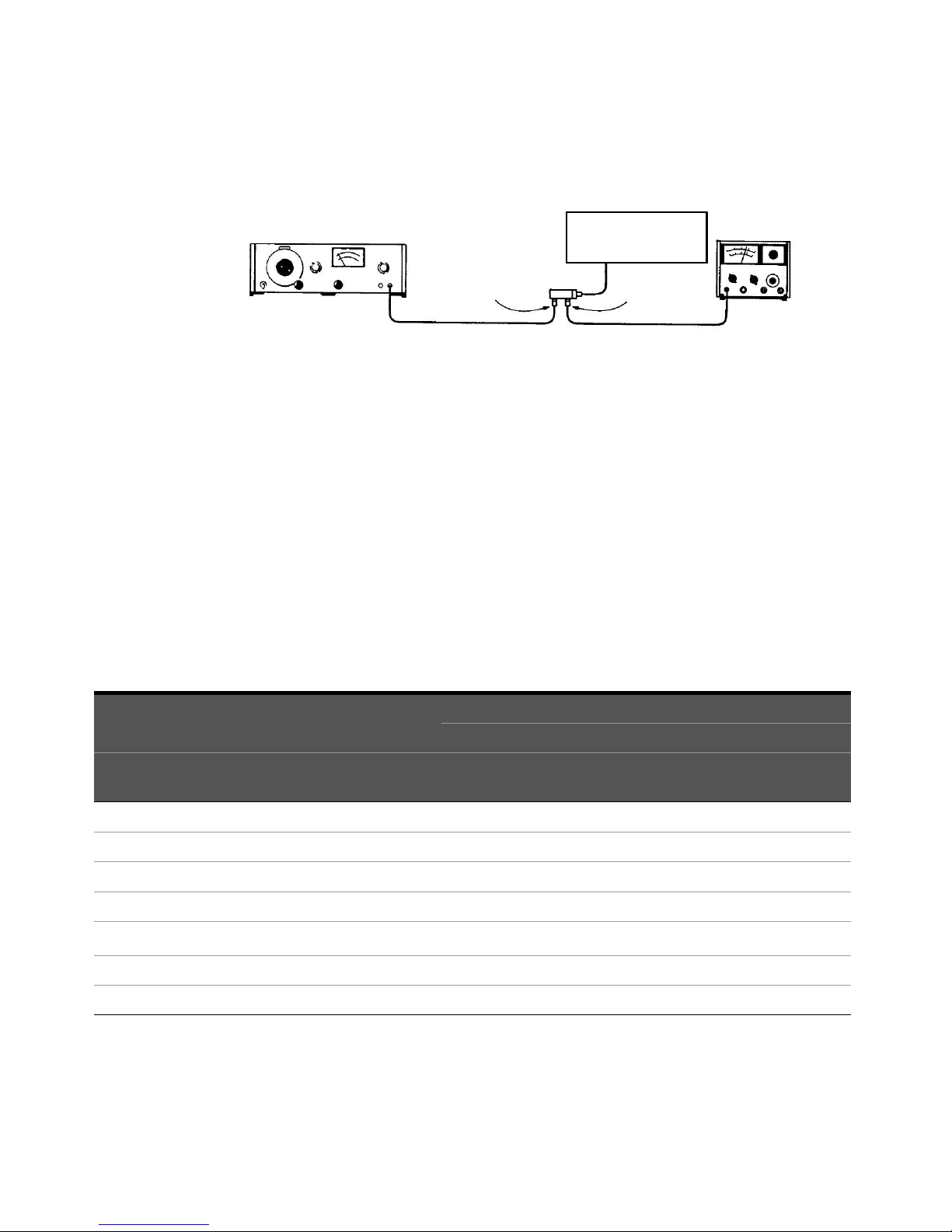
Description
The attenuator is driven from a 50-ohm signal source at 1 kHz. The output level
from the attenuator is detected by a narrow-bandwidth voltmeter. The attenuator
and detector range switches are stepped together and the variations in level
noted. This verifies that each attenuator section is being properly switched and
checks the low-frequency accuracy of the attenuator.
The SWR meter used in this check is calibrated for a square-law detector.
Therefore, the range changes and errors (read in dB) are twice that indicated by
the meter.
30 Keysight 8494/95/96G/H Operating and Service Manual
Operating Guides 3
Test oscillator
Adapter
Attenuator
Adapter
Solenoid driver
circuits
50 Ω
SWR Meter
Input
Figure 3-1 Operator’s check setup
Procedure
1 Connect equipment as shown in Figure 3-1 with the attenuator set to 0 dB
attenuation.
2 Set the test oscillator to 0.3 Vrms at 1 kHz.
3 Set SWR meter range to 2 dB (expanded) [or for the 8494G/H to 10 dB
(expanded)] and adjust its bandwidth to the center of the adjustment range.
Fine-tune the oscillator frequency to obtain maximum meter indication.
4 Set attenuator and SWR meter range switch as listed in Table and verify that
the SWR meter indicates within the limits shown.
Table 3-1 Attenuator and SWR settings
SWR meter range
(dB)
[a]
8495G/H
8496G/H
22 4 40 40 1.85 0.15 - - 2.15 0.85
8494G/H 8495G/H 8496G/H 8494G/H
8494G/H
10 2 0 0 0 - - Set to 0.0 Set to 0.5 - -
10 6 1 10 10 0.40 1.40 - - 0.60 1.60
10 12 2 20 20 0.90 0.30 - - 1.10 0.70
10 16 3 30 30 1.35 1.25 - - 1.65 1.75
10
12 26 5 50 50 0.35 1.10 - - 0.65 1.90
12 32 6 60 60 0.85 0.00 - - 1.15 1.00
Attenuation (dB)
Minimum Actual Maximum
8495G/H
8496G/H
Meter indication (dB)
8494G/H
8495G/H
8496G/H
8494G/H
8495G/H
8496G/H
Keysight 8494/95/96G/H Operating and Service Manual 31

3 Operating Guides
Table 3-1 Attenuator and SWR settings (continued)
SWR meter range
(dB)
[a]
8495G/H
8496G/H
[a]
36
[a]
42
[a]
46
[a]
52
[a]
56
8494G/H 8495G/H 8496G/H 8494G/H
8494G/H
12
12
14
14
14
[a] Adjust range by 2 dB, if needed, to obtain an on-scale indication
Attenuation (dB)
7 70 70 1.30 0.90 - - 1.70 2.10
8 - 80 1.80 -0.15 - - 2.20 1.15
9 - 90 0.30 0.75 - - 0.70 2.25
10 - 100 0.80 -0.30 - - 1.20 1.30
11 - 110 1.75 0.60 - - 1.75 2.40
Meter indication (dB)
Minimum Actual Maximum
8495G/H
8496G/H
8494G/H
8495G/H
8496G/H
8494G/H
8495G/H
8496G/H
32 Keysight 8494/95/96G/H Operating and Service Manual

Performance tests
The 8494/95/96G/H Attenuators can be tested to the accuracy of the
specifications with a network analyzer or equivalent equipment of suitable
accuracy. If a network analyzer is available, test instrument using the procedure in
the analyzer's operating manual.
Service instructions
Service
The 8494/95/96G/H does not have internal adjustments and should not be
opened; it should only be repaired by service-trained personnel. Should it become
necessary to return the 8494/95/96G/H for repair or service, contact your nearest
Keysight Sales and Service Center. Refer to “Sales and Technical Support” on
page 4 of this manual.
Maintenance
Operating Guides 3
The connectors, particularly the connector faces, must be kept clean. For
instruction on connecting and care of your connectors, refer to the Microwave
Connector Care Quick Reference Card (08510-90360).
Keysight 8494/95/96G/H Operating and Service Manual 33

3 Operating Guides
THIS PAGE HAS BEEN INTENTIONALLY LEFT BLANK.
34 Keysight 8494/95/96G/H Operating and Service Manual

This information is subject to change
without notice. Always refer to the
English version at the Keysight
website for the latest revision.
© Keysight Technologies 2014 - 2019
Edition 7, January 10, 2019
Printed in Malaysia
*08495-90025*
08495-90025
www.keysight.com
 Loading...