


Keysight 34921A-34925A
Low Frequency Multiplexer
Modules
User’s Guide

Notices
CAUTION
WARNING
Copyright Notice
© Keysight Technologies 2008-2019
No part of this manual may be
reproduced in any form or by any
means (including electronic storage
and retrieval or translation into a
foreign language) without prior
agreement and written consent from
Keysight Technologies as governed by
United States and international
copyright laws.
Trademarks
Microsoft® and Windows® are U.S.
registered trademarks of Microsoft
Corporation.
Manual Part Number
34980-90021
Edition
Edition 3, July 1, 2019
Printed in:
Printed in Malaysia
Published by:
Keysight Technologies
Bayan Lepas Free Industrial Zone,
11900 Penang, Malaysia
Technology Licenses
The hard ware and/or software
described in this document are
furnished under a license and may be
used or copied only in accordance with
the terms of such license.
Declaration of Conformity
Declarations of Conformity for this
product and for other Keysight
products may be downloaded from the
Web. Go to http://www.keysight.com/
go/conformity. You can then search by
product number to find the latest
Declaration of Conformity.
U.S. Government Rights
The Software is “commercial computer
software,” as defined by Federal
Acquisition Regulation (“FAR”) 2.101.
Pursuant to FAR 12.212 and 27.405-3
and Department of Defense FAR
Supplement (“DFARS”) 227.7202, the
U.S. government acquires commercial
computer software under the same
terms by which the software is
customarily provided to the public.
Accordingly, Keysight provides the
Software to U.S. government
customers under its standard
commercial license, which is embodied
in its End User License Agreement
(EULA), a copy of which can be found
at http://www.keysight.com/find/
sweula. The license set forth in the
EULA represents the exclusive authority
by which the U.S. government may use,
modify, distribute, or disclose the
Software. The EULA and the license set
forth therein, does not require or
permit, among other things, that
Keysight: (1) Furnish technical
information related to commercial
computer software or commercial
computer software documentation that
is not customarily provided to the
public; or (2) Relinquish to, or
otherwise provide, the government
rights in excess of these rights
customarily provided to the public to
use, modify, reproduce, release,
perform, display, or disclose
commercial computer software or
commercial computer software
documentation. No additional
government requirements beyond
those set forth in the EULA shall apply,
except to the extent that those terms,
rights, or licenses are explicitly required
from all providers of commercial
computer software pursuant to the FAR
and the DFARS and are set forth
specifically in writing elsewhere in the
EULA. Keysight shall be under no
obligation to update, revise or
otherwise modify the Software. With
respect to any technical data as
defined by FAR 2.101, pursuant to FAR
12.211 and 27.404.2 and DFARS
227.7102, the U.S. government
acquires no greater than Limited Rights
as defined in FAR 27.401 or DFAR
227.7103-5 (c), as applicable in any
technical data.
Warranty
THE MATERIAL CONTAINED IN THIS
DOCUMENT IS PROVIDED “AS IS,” AND
IS SUBJECT TO BEING CHANGED,
WITHOUT NOTICE, IN FUTURE
EDITIONS. FURTHER, TO THE
MAXIMUM EXTENT PERMITTED BY
APPLICABLE LAW, KEYSIGHT
DISCLAIMS ALL WARRANTIES, EITHER
EXPRESS OR IMPLIED, WITH REGARD
TO THIS MANUAL AND ANY
INFORMATION CONTAINED HEREIN,
INCLUDING BUT NOT LIMITED TO THE
IMPLIED WARRANTIES OF
MERCHANTABILITY AND FITNESS FOR
A PARTICULAR PURPOSE. KEYSIGHT
SHALL NOT BE LIABLE FOR ERRORS
OR FOR INCIDENTAL OR
CONSEQUENTIAL DAMAGES IN
CONNECTION WITH THE FURNISHING,
USE, OR PERFORMANCE OF THIS
DOCUMENT OR OF ANY INFORMATION
CONTAINED HEREIN. SHOULD
KEYSIGHT AND THE USER HAVE A
SEPARATE WRITTEN AGREEMENT
WITH WARRANTY TERMS COVERING
THE MATERIAL IN THIS DOCUMENT
THAT CONFLICT WITH THESE TERMS,
THE WARRANTY TERMS IN THE
SEPARATE AGREEMENT SHALL
CONTROL.
Safety Information
A CAUTION notice denotes a hazard. It
calls attention to an operating
procedure, practice, or the like that, if
not correctly performed or adhered to,
could result in damage to the product
or loss of important data. Do not
proceed beyond a CAUTION notice
until the indicated conditions are fully
understood and met.
A WARNING notice denotes a hazard. It
calls attention to an operating
procedure, practice, or the like that, if
not correctly performed or adhered to,
could result in personal injury or death.
Do not proceed beyond a WARNING
notice until the indicated conditions are
fully understood and met.
2 Keysight 34921A-34925A User’s Guide

Safety Symbols
The following symbols on the instrument and in the documentation indicate
precautions which must be taken to maintain safe operation of the instrument.
Alternating current (AC) Caution, risk of electric shock
Frame or chassis (ground) terminal
Standby supply. Unit is not completely
disconnected from ac mains when
switch is off
Caution, risk of danger (refer to this
manual for specific Warning or Caution
information)
Keysight 34921A-34925A User’s Guide 3

Additional Safety Notices
The following general safety precautions must be observed during all phases of
operation of this instrument. Failure to comply with these precautions or with
specific warnings or instructions elsewhere in this manual violates safety
standards of design, manufacture, and intended use of the instrument. Keysight
Technologies assumes no liability of the customer’s failure to comply with the
requirements.
General
Do not use this products in any manner not specified by the manufacturer. The
protective features of this product may be impaired if it is used in a manner not
specified in the operation instructions.
Before Applying Power
Verify that all safety precautions are taken. Make all connections to the unit before
applying power.
Ground the Instrument
This product is provided with protective earth terminals. To minimize shock
hazard, the instrument must be connected to the ac power mains through a
grounded power cable, with the ground wire firmly connected to an electrical
ground (safety ground) at the power outlet. Any interruption of the protective
(grounding) conductor or disconnection of the protective earth terminal will cause
a potential shock hazard that could result in personal injury.
Do Not Operate in an Explosive Atmosphere
Do not operate the instrument in the presence of flammable gases or fumes.
4 Keysight 34921A-34925A User’s Guide

Do Not Remove the Instrument Cover
Only qualified, service-trained personal who are aware of the hazards involved
should remove instrument covers. Always disconnect the power cable and any
external circuits before removing the instrument cover.
Do Not Modify the Instrument
Do not install substitute parts or perform any unauthorized modification to the
product. Return the product to an Keysight Sales and Service Office for service
and repair to ensure that safety features are maintained.
In Case of Damage
Instruments that appear damaged or defective should be made inoperative and
secured against unintended operation until they can be repaired by qualified
service personnel.
Keysight 34921A-34925A User’s Guide 5

Waste Electrical and Electronic Equipment (WEEE) Directive 2002/ 96/EC
This instrument complies with the WEEE Directive (2002/96/EC) marking
requirement. This affixed product label indicates that you must not discard this
electrical or electronic product in domestic household waste.
Product category:
With reference to the equipment types in the WEEE directive Annex 1, this
instrument is classified as a “Monitoring and Control Instrument” product.
The affixed product label is as shown below.
Do not dispose in domestic household waste.
To return this unwanted instrument, contact your nearest Keysight Service Center,
or visit http://about.keysight.com/en/companyinfo/environment/takeback.shtml
for more information.
Sales and Technical Support
To contact Keysight for sales and technical support, refer to the support links on
the following Keysight websites:
– www.keysight.com/find/34980a
(product-specific information and support, software and
documentation updates)
– www.keysight.com/find/assist
(worldwide contact information for repair and service)
6 Keysight 34921A-34925A User’s Guide

Table of Contents
Safety Symbols . . . . . . . . . . . . . . . . . . . . . . . . . . . . . . . . . . . . . . . . . . . . .3
Additional Safety Notices . . . . . . . . . . . . . . . . . . . . . . . . . . . . . . . . . . . . .4
General . . . . . . . . . . . . . . . . . . . . . . . . . . . . . . . . . . . . . . . . . . . . . . . . . 4
Before Applying Power . . . . . . . . . . . . . . . . . . . . . . . . . . . . . . . . . . . . 4
Ground the Instrument . . . . . . . . . . . . . . . . . . . . . . . . . . . . . . . . . . . .4
Do Not Operate in an Explosive Atmosphere . . . . . . . . . . . . . . . . . . .4
Do Not Remove the Instrument Cover . . . . . . . . . . . . . . . . . . . . . . . .5
Do Not Modify the Instrument . . . . . . . . . . . . . . . . . . . . . . . . . . . . . . .5
In Case of Damage . . . . . . . . . . . . . . . . . . . . . . . . . . . . . . . . . . . . . . . .5
Waste Electrical and Electronic Equipment (WEEE) Directive 2002/96/
EC . . . . . . . . . . . . . . . . . . . . . . . . . . . . . . . . . . . . . . . . . . . . . . . . . . . . .6
Product category: . . . . . . . . . . . . . . . . . . . . . . . . . . . . . . . . . . . . . . . . 6
Sales and Technical Support . . . . . . . . . . . . . . . . . . . . . . . . . . . . . . . . . .6
Low Frequency Multiplexer Modules . . . . . . . . . . . . . . . . . . . . . . . . . . . . 9
Multiplexer Module Capabilities . . . . . . . . . . . . . . . . . . . . . . . . . . . . . 9
Measurement Functions for the Multiplexer Modules . . . . . . . . . . .10
Operating Considerations . . . . . . . . . . . . . . . . . . . . . . . . . . . . . . . . .11
SCPI Programming Examples for the Multiplexer Modules . . . . . . . . . .13
34921A 40-Channel Armature Multiplexer with Low Thermal Offset . .17
34921A Simplified Schematic . . . . . . . . . . . . . . . . . . . . . . . . . . . . . .19
34921A D-Sub Connectors . . . . . . . . . . . . . . . . . . . . . . . . . . . . . . . .20
34921T Terminal Block . . . . . . . . . . . . . . . . . . . . . . . . . . . . . . . . . . . 22
34922A 70-Channel Armature Multiplexer . . . . . . . . . . . . . . . . . . . . . . 24
34922A Simplified Schematic . . . . . . . . . . . . . . . . . . . . . . . . . . . . . .25
34922A D-Sub Connectors . . . . . . . . . . . . . . . . . . . . . . . . . . . . . . . .26
34922T Terminal Blocks . . . . . . . . . . . . . . . . . . . . . . . . . . . . . . . . . .28
34923A 40/80-Channel Reed Multiplexer . . . . . . . . . . . . . . . . . . . . . . .31
Two-Wire Mode . . . . . . . . . . . . . . . . . . . . . . . . . . . . . . . . . . . . . . . . .32
Four-Wire Mode . . . . . . . . . . . . . . . . . . . . . . . . . . . . . . . . . . . . . . . . .32
One-Wire Mode . . . . . . . . . . . . . . . . . . . . . . . . . . . . . . . . . . . . . . . . .33
34923A Simplified Schematic for Two- or Four-Wire Mode . . . . . .34
Keysight 34921A-34925A User’s Guide 7

34923A D-Sub Connectors for Two- or Four-Wire Mode . . . . . . . . 35
34923T-001 Terminal Block for Two-Wire or Four-Wire Mode . . . 37
34923A Simplified Schematic for One-Wire Mode . . . . . . . . . . . . . 39
34923A D-Sub Connectors for One-Wire Mode . . . . . . . . . . . . . . . 40
34923T-002 Terminal Block for One-Wire Mode . . . . . . . . . . . . . . 42
34924A 70-Channel Reed Multiplexer . . . . . . . . . . . . . . . . . . . . . . . 43
34924A Simplified Schematic . . . . . . . . . . . . . . . . . . . . . . . . . . . . . . 45
34924A D-Sub Connectors . . . . . . . . . . . . . . . . . . . . . . . . . . . . . . . . 46
34924T Terminal Blocks . . . . . . . . . . . . . . . . . . . . . . . . . . . . . . . . . . 48
34925A 40/80-Channel Optically-Isolated FET Multiplexer . . . . . . . . 51
Two-Wire Mode . . . . . . . . . . . . . . . . . . . . . . . . . . . . . . . . . . . . . . . . . 51
Four-Wire Mode . . . . . . . . . . . . . . . . . . . . . . . . . . . . . . . . . . . . . . . . 52
One-Wire Mode . . . . . . . . . . . . . . . . . . . . . . . . . . . . . . . . . . . . . . . . . 52
Interlock Protection . . . . . . . . . . . . . . . . . . . . . . . . . . . . . . . . . . . . . . 52
Overvoltage Protection . . . . . . . . . . . . . . . . . . . . . . . . . . . . . . . . . . . 53
34925A Simplified Schematic for Two- or Four-Wire Mode . . . . . . 54
34925A D-Sub Connectors for Two- or Four-Wire Mode . . . . . . . . 55
34925T-001 Terminal Block for Two-Wire or Four-Wire Mode . . . 57
34925A Simplified Schematic for One-Wire Mode . . . . . . . . . . . . . 59
34925A D-Sub Connectors for One-Wired Mode . . . . . . . . . . . . . . 60
34925T-002 Terminal Block for One-Wire Mode . . . . . . . . . . . . . . 62
8 Keysight 34921A-34925A User’s Guide

Low Frequency Multiplexer Modules
This User’s Guide covers the following five plug-in modules for the Keysight
34980A Multifunction Switch/Measure Unit:
34921A 40-channel armature multiplexer w/low thermal offset
34922A 70-channel armature multiplexer
34923A 40/80-channel reed multiplexer
34924A 70-channel reed multiplexer
34925A 40-channel optically isolated FET multiplexer
Multiplexer Module Capabilities
Each multiplexer (MUX) module features two banks of channels, providing broad
multiplexing and measurement capabilities. Briefly:
– You can connect a MUX to an external instrument, and/or switch multiple
analog signals to the internal DMM.
– With the 34921A, 34922A, 34923A, and the 34924A modules, you can close
more than one channel in each bank simultaneously (N:1 configuration).
– Since the 34925A module is protected with overvoltage circuitry, you can close
only one channel in each bank at one time (1:N configuration).
– You can connect multiple MUXes to the built-in Analog Buses, which allow you
to scan as many as 560 2-wire (differential) channels or 640 1-wire
(single-ended) channels in one 34980A mainframe.
Keysight 34921A-34925A User’s Guide 9

Measurement Functions for the Multiplexer Modules
The MUX modules support the DMM measurement functions shown in the
following table.
Measurement Function(s)
34921A
40-ch
Armature
Mux
34922A
70-ch
Armature
Mux
34923A
40-ch
Reed Mux
(2-Wire)
34923A
80-ch
Reed Mux
(1-Wire)
34924A
70-ch
Reed Mux)
34925A
40-ch
FET Mux
(2-Wire)
34925A
80-ch
FET Mux
(1-Wire)
Voltage, AC/DC Yes Yes Yes Yes Yes Yes Yes
Current, AC/DC
Yes
[a]
No No No No No No
Frequency/Period Yes Yes Yes Yes Yes Yes Yes
Yes
Yes
Yes
Yes
Yes
Yes
[e]
[e]
[c],[d]
[e]
[e]
[e]
Ohms 2-Wire Yes Yes
Ohms 4-Wire Yes Yes
Thermocouple
Yes
[b]
Yes
[c]
RTD 2-Wire Yes Yes
RTD 4-Wire Yes Yes
Thermistor Yes Yes
[a] Direct current measurements are allowed on channels 41 through 44 only (for all other channels, external shunts are required).
[b] Optional 34921T Terminal Block is required for thermocouple measurements with built-in internal reference junction.
[c] A fixed or external reference junction temperature is required for thermocouple measurement with this module.
[d] Impact of higher offset voltage specification (< 50 μV) must be taken into consideration.
[e] 1 kΩ or higher range used unless 100Ω series resistors are bypassed on module.
[f] 10 kΩ or higher range used for loads over approximately 300Ω due to series resistance of FET channels.
Yes
Yes
Yes
Yes
No
[c],[d]
No
[e]
[e]
[e]
Yes
Yes
Yes
Yes
Yes
Yes
[e]
[e]
[c],[d]
[e]
[e]
[e]
[f]
Yes
[f]
Yes
[c]
Yes
No No
[f]
Yes
No No
Yes
Yes
[f]
No
[c]
No
10 Keysight 34921A-34925A User’s Guide

Operating Considerations
CAUTION
Current Ratings
See the Introduction to the Plug In Modules chapter of the 34980A Mainframe
User’s Guide for detailed environmental operating conditions for the 34980A
mainframe and its installed modules. That guidance sets maximum per channel
current ratings at rated voltage for pollution degree 1 (dry) and pollution degree 2
(possible condensation) conditions, for all of the multiplexer modules.
Safety Interlock
The Analog Buses of the 34980A are capable of carrying 300V signals. The MUX
modules have a hardware Safety Interlock feature that automatically opens the
Analog Bus relays when the associated interlock pins on the D-sub connectors
(faceplate) lose continuity. This prevents signals on the Analog Buses from being
present on the D-sub connector pins. Optional terminal blocks available from
Keysight automatically provide continuity for these interlock pins. If cables are
used, you must provide continuity for the interlock pins in your DUT assembly. See
the pinout information later in this guide for the location of interlock pins on each
module.
The MUX modules have Analog Bus relays on each of their two banks. Therefore,
the interlock pins are present on both the Bank 1 and Bank 2 D-sub connectors on
the MUX modules.
Normally, if you attempt to connect to the Analog Buses without a terminal block or
cable connected, an error is generated. The SYSTem:ABUS:INTerlock:SIMulate
command allows you to temporarily disable errors generated by the Safety
Interlock feature and enables the simulation mode. Although Safety Interlock
errors are suppressed in this mode, the actual Analog Bus relays affected by the
Safety Interlock are disabled as long as no terminal block or cable is connected to
the module.
The Safety Interlock feature is implemented in hard ware on the modules and
cannot be circumvented. Regardless of whether the simulation mode is
enabled or disabled, all Analog Bus connections are prohibited as long as no
terminal block or properly-wired cable is connected to the module.
Keysight 34921A-34925A User’s Guide 11

– The simulation mode applies to the entire mainframe and cannot be selectively
used on individual modules.
– When the simulation mode is enabled, the Analog Bus relays will appear to
close and open as directed. For example, no errors are generated if you close
an Analog Bus relay from the front panel, remote interface, or Web Interface.
However, remember that the Safety Interlock feature prevents the actual
hardware state of the Analog Bus relays from being changed. When you
connect a terminal block or cable to the module, the Analog Bus relays will be
closed.
– The simulation setting is stored in volatile memory and will be lost when power
is turned off. To re-enable the simulation mode after power has been off, you
must send the command again.
12 Keysight 34921A-34925A User’s Guide

SCPI Programming Examples for the Multiplexer Modules
The programming examples below provide you with SCPI command examples to
use for actions specific to the MUX modules.
The slot and channel addressing scheme used in these examples follow the form
sccc where s is the mainframe slot number (1 through 8) and ccc is the three-digit
channel number. For information on specific MUX channel configurations, refer to
the simplified schematics contained in each MUX section of this manual.
For complete information on the SCPI commands used to program the 34980A,
with example programs, refer to the Keysight 34980A Programmer’s Reference
which can be downloaded from www.keysight.com/find/34980A.
Opening and Closing Channels
Example: Closing and opening channels on the armature and reed MUX
modules
channel in a bank is defined to be part of the scan list, and a scan is occurring,
attempting to close another channel (including Analog Bus channels) within the
same bank will result in an error. Channel closures in the other bank are allowed
as long as no channels are part of the scan list.
The following commands close and open channels 13 and 15 through 18 in slot 3.
ROUTe:CLOSe (@3013,3015:3018)
ROUTe:OPEN (@3013,3015:3018)
This command closes the specified channels on a MUX module. If any
Example: Closing channels on the FET MUX mod ule
supports a 1:N type closure, meaning that you can have only one channel per
bank closed at a time. The following command closes then automatically opens
each channel from 1-19 (Bank 1) in succession, leaving channel 20 closed. Then
the command continues closing and opening channels 21 to 39 (Bank 2), then
leaving channel 40 closed. At the end, only channels 20 and 40 will be closed,
while all other channels will have been closed and then opened. In this process, a
channel will open before the next channel in succession closes, making this a
“break-before-make” series.
ROUTe:CLOSe (@3001:3040)
The following command opens the closed channel on Bank 1 of a FET MUX
module in slot 3, and closes channel 15 on that bank.
ROUTe:CLOSe (@3015)
Keysight 34921A-34925A User’s Guide 13
The FET MUX module

Example: Closing and opening Analog Bus relays
connects the Analog Buses to Bank 1 (via the Analog Bus relays on Bank 1) for a
module in slot 3.
ROUTe:CLOSe (@3911,3912,3913,3914)
ROUTe:OPEN (@3911,3912,3913,3914)
The Analog Bus relays (numbered s911, s912, s913, etc.) on the MUX modules are
ignored if they are included in a range of channels. An error will be generated if an
Analog Bus relay is specified as the first or last channel in a range of channels. For
example, the following command closes all valid channels between channel 30
(slot 1) and channel 5 (slot 2). In addition, this command closes Analog Bus relay
911 on the module in slot 1 (Bank 1). Note that although the specified range of
channels includes the other Analog Bus relays, they are ignored and are not
closed by this command.
ROUTe:CLOSe (@1030:2005,1911)
The following command
Example: Querying channels for open or close state
command returns a 1 (true) or 0 (false) state of channel 036 for a module in slot 3.
ROUTe:CLOSe (@3036)
ROUTe:CLOSe? (@3036) !Returns a 1
ROUTe:OPEN? (@3036) !Returns a 0
The following
Making Measurements
Example: Making voltage measurements
configures channels 9 and 10 in slot 4 for DC voltage measurements, triggers the
internal DMM to scan channels 9 and 10, and returns the reading. The 1 V range is
selected with 1 mV resolution.
MEASure:VOLTage:DC? 1,0.001, (@4009,4010)
Example: Making voltage measurements using INITiate and FETCh?
The following program segment shows how to use the INITiate command with
the CONFigure and FETCh? commands. The ROUTe:SCAN command puts
channels 3 and 8 (of a module in slot 1) into the scan list (and redefines the scan
list). The INITiate command scans the specified channels, and then sends the
readings to memory. The FETCh? command transfers the readings from memory
to the user.
The following command
14 Keysight 34921A-34925A User’s Guide

CONFigure:VOLTage:DC 10,0.003,(@1003,1008)
NOTE
NOTE
ROUTe:SCAN (@1003,1008)
INITiate
FETCh?
Example: Making current measurements
channel 43 for a 34921A modules in slot 7 for dc current measurements, triggers
the internal DMM to scan the channel, and then sends the reading to the output
buffer of the 34980A. The default settings for range (autorange) and resolution (1
PLC) are used for the measurement.
MEASure:CURRent:DC? (@7043)
The following command configures
Configuring a Module
Example: Configuring a module for 2-wire or 1-wire mode
command configures a MUX module in slot 4 for 1-wire mode. Because you can
configure only the 34923A and 34925A MUX modules (and the 34933A matrix
module) for either 2-wire or 1-wire mode, an error is generated if you send this
command to a slot that does not contain one of those three modules. If you are
using terminal blocks with these modules, be sure to use the corresponding
2-wire or 1-wire terminal block.
SYSTem:MODule:WIRE:MODE WIRE1,4
When using a command to configure the system, the new configuration does not
take effect until you cycle power on the 34980A.
Example: Querying the system for module Identify
returns the identity of the module installed in slot 7.
The following command
The following
SYSTem:CTYPe? 7
For the 34923A and the 34925A MUX modules, the query response may include
a suffix to indicate a 1-wire configuration. For example, the response for the
34923A will be either "34923A" (differential mode) or "34923A-1W"
(single-ended mode).
Keysight 34921A-34925A User’s Guide 15

Querying and Clearing Cycle Count, and Resetting Modules
NOTE
Example: Querying the cycle count for a relay
returns the cycle count on channel 7 and channel 16 for a MUX module in slot 1.
DIAGnostic:RELay:CYCLes? (@1007,1016)
The 34925A will return 0 for relay counts because the FET relays on that module
are non-mechanical and have an undefined lifetime.
Example: Clearing the cycle count for a relay
the cycle count to zero on the channels 7 and 16 for a MUX module in slot 1.
DIAGnostic:RELay:CYCLes:CLEar (@1007,1016)
Example: Resetting module(s) to power-on state
resets a module in slot 4 to its power-on state.
SYSTem:CPON 4
The following command
The following command resets
The following command
16 Keysight 34921A-34925A User’s Guide

34921A 40-Channel Armature Multiplexer with Low Thermal Offset
NOTE
The 34921A 40-Channel Armature Multiplexer (40-Ch Arm MUX) is divided into
two banks with 20 latching armature switches (channels 1-20 and 21-40) in each.
This module also offers four additional fused relays (channels 41-44) for making
AC and DC current measurements with the internal DMM with no external shunts
needed. These current channels feature “make-before-break” connections to
ensure continuous current flow when switching from one current channel to
another. The current fuses are replaceable. Refer to the 34980A Service Guide for
specific information about these fuses.
This module also contains nine armature Analog Bus relays (channels 911-914,
921-924, and 931), four on each bank that can connect the bank relays to the
system Analog Buses and one that connects the current relays to the current input
of the DMM. Through ABus1 and ABus2 you can connect any of the channels to
the internal DMM for voltage or resistance measurements. Refer to the simplified
schematic on page 19.
ABus1 consists of three wires that are used for current and voltage
measurements. A separate current bus on ABus1 connects to the internal DMM
current measurement input and this bus can be connected only to channels 41
through 44. The current channel low (L) signal path is common with the ABus1
low (L) signal path. You cannot measure current and voltage on ABus1
simultaneously.
Using program commands or the mainframe front panel, you can control each of
the channel switches individually, and thus configure the 34921A module in these
modes:
– two independent 20-channel 2-wire MUXes. This configuration requires
neither using external wiring nor connecting through the internal Analog
Buses.
– one 20-channel 4-wire MUX. This configuration requires neither using external
wiring nor connecting through the internal Analog Buses. For 4-wire resistance
measurements, the instrument automatically pairs channel n on Bank 1
(source) with channel n+20 on Bank 2 (sense) to provide these connections.
Four-wire controls occur only when doing 4-wire measurement operations
through the internal DMM, such as MEASure:FRESistance? or scanning a
channel previously configured as 4-wire.
Keysight 34921A-34925A User’s Guide 17

– one 40-channel 2-wire MUX. You must use external wiring or connect through
the internal Analog Bus relays for this configuration. For example, closing
Analog Bus channels 913 and 923 connects Bank 1 and Bank 2 through
ABus3. Or, externally you can connect COM1 to COM2 to create this
configuration.
Low thermal offset voltage makes the 34921A ideal for low-level signal switching.
The 34921T optional terminal block provides a built-in thermocouple reference
junction that helps minimize errors due to thermal offset when you measure
thermocouples.
This module has capability to scan as many as 100 channels/second using the
internal DMM. With the automatic “break-before-make” connection operation,
you are assured that no two signals are connected to each other during a scan.
When using the module in a non-scanning mode, you can close as many channels
as you wish.
This module is safety interlock protected, which means whenever the D-sub
connector end of the modules is exposed, the Analog Bus relays automatically
open and disconnect from the Analog Bus. For more information, see “Safety
Interlock” on page 11 and “34921A D-Sub Connectors” on page 20.
When power is off, all channel relays maintain state, and the Analog Bus relays
open.
18 Keysight 34921A-34925A User’s Guide

34921A Simplified Schematic
026
027
028
029
030
ABus 2
DMM
(SENS)
ABus3
ABus 4
931
923
913 914
924
922
912911
921
DMM
(MEAS)
L
001
002
003
004
005
H
L
006
007
008
009
010
H
L
011
012
013
014
015
L
H
016
017
018
019
020
021
022
023
024
025
H
L
031
032
033
034
035
036
037
038
039
040
L
H
L
H
L
Current
Fuse
Fuse
Fuse
Fuse
0
42
0
43
0
41
LH
LH
LH
LH
LH
LHLH
LH
H
L
L
L
L
L
0
44
LH
H
LH
COM 2
Bank 2
Current
Bank 1
COM 1
Analog Buses
I
I
I
I
I
ABus 1
NOTE: The three-digit number assigned to each switch represents the channel number.
NOTE:
Bank Relays: Armature latching
Analog Bus Relays: Armature
non-latching
This drawing shows two independent 20-channel 2-wire MUXes.
Keysight 34921A-34925A User’s Guide 19

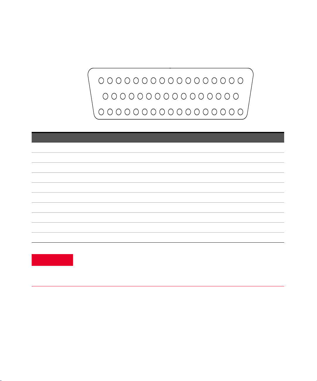
34921A D-Sub Connectors
For orientation, the D-sub connector
end of the module is facing you.
Bank 2
Bank 1
17L
34
35
36 37
38
39 40
41
42
43 44 45
46
47 48 49
50
18
19 20
21 22
23
24
25 26
27 28
29 30 31 32
33
1 2 3 4 5 6 7 8 9 1011121314151617
TSIL* 11H 11L 7H 7L 17H 13H 13L 9H 9L 19H 19L 15H 15L Interlock 1
Interlock11H 1L 2H 2L 3H 3L
COM1HCOM
1L
4H 4L 14H 14L 5H 5L 20H 20L
18HGND 6H 6L 16H 16L 12H 12L 8H 8L 18L 10H 10L
AMP
41L
AMP
41I
AMP
42L
AMP
42I
*TSIL = Temperature
Sensor Interface Line.
Provides thermocouple
reference sensor serial
output line to the
mainframe processor.
50-Pin
D-Sub Male
Connector
WARNING
Bank 1
Description Pin Description Pin Description Pin Description Pin Description Pin
1H 1 6H 35 11H 19 16H 37 COM1 H 7
1L 2 6L 36 11L 20 16L 38 COM1 L 8
2H 3 7H 21 12H 39 17H 23 Interlock 1 17
2L 4 7L 22 12L 40 17L 24 Interlock 1 33
3H 5 8H 41 13H 25 18H 43 GND 34
3L 6 8L 42 13L 26 18L 44 TSIL* 18
4H 9 9H 27 14H 11 19H 29 AMP 41L 47
4L 10 9L 28 14L 12 19L 30 AMP 41I 48
5H 13 10H 45 15H 31 20H 15 AMP 42L 49
5L 14 10L 46 15L 32 20L 16 AMP 42I 50
As a safety feature, interlock 1 pins (17 and 33) on Bank 1 must be shorted to
enable the Bank 1 Analog Bus relays to close. The optional 34921T terminal
block shorts these pins for you. This feature protects inadvertent routing of
high voltages from the Analog Bus to the D-sub connector of the module.
20 Keysight 34921A-34925A User’s Guide
Bank 2
34 35 36 37 38 39 40 41 42 43 44 45 46 47 48 49 50
23L Interlock 221H 21L 22H 22L 23H
COM2HCOM
2L
24H 24L 34H 34L 25H 25L 40H 40L
1234567891011121314151617
37LTSIL* 31H 31L 27H 27L 37H 33H 33L 29H 29L 39H 39L 35H 35L Interlock 2
18 19 20 21 22 23 24 25 26 27 28 29 30 31 32 33
GND 26H 26L 36H 36L 32H 32L 28H 28L 38H 38L 30H 30L
AMP
43L
AMP
43I
AMP
44L
AMP
44I
50-Pin
D-Sub Male
Connector
*TSIL = Temperature
Sensor Interface Line.
Provides thermocouple
reference sensor serial
output line to the
mainframe processor.
WARNING
Description Pin Description Pin Description Pin Description Pin Description Pin
21H 1 26H 35 31H 19 36H 37 COM2 H 7
21L 2 26L 36 31L 20 36L 38 COM2 L 8
22H 3 27H 21 32H 39 37H 23 Interlock 2 17
22L 4 27L 22 32L 40 37L 24 Interlock 2 33
23H 5 28H 41 33H 25 38H 43 GND 34
23L 6 28L 42 33L 26 38L 44 TSIL* 18
24H 9 29H 27 34H 11 39H 29 AMP 43L 47
24L 10 29L 28 34L 12 39L 30 AMP 43I 48
25H 13 30H 45 35H 31 40H 15 AMP 44L 49
25L 14 30L 46 35L 32 40L 16 AMP 44I 50
As a safety feature, interlock 2 pins (17 and 33) on Bank 2 must be shorted to
enable the Bank 2 Analog Bus relays to close. The optional 34921T terminal
block shorts these pins for you. This feature protects inadvertent routing of
high voltages from the Analog Bus to the D-sub connector of the module.
Keysight 34921A-34925A User’s Guide 21

34921T Terminal Block
NOTE
Temperature
Sensor
34921T (viewed from bottom side)
External
Reference
This terminal block with screw-type connections is labeled with the model number
and the abbreviated module name. In addition, space is available on the label for
you to write the slot number.
All modules that connect to the internal DMM are interlock protected. This
means that when an installed module is exposed (no terminal block or cable is
connected), the Analog Bus relays are open and disconnected from the Analog
Buses. See “Safety Interlock” on page 11 for further information.
The 34921T is the only terminal block that provides an isothermal block with
temperature reference for thermocouple measurements. The temperature sensor
is located on the bottom side of the PC board as shown below. Also shown are two
holes that you can use for connecting an external temperature reference to the
terminal block.
22 Keysight 34921A-34925A User’s Guide

CAUTION
When wiring the terminal block via cables to the mainframe, make sure the
W
i
r
e
S
i
z
e
:
2
0
A
W
G
T
y
p
i
c
a
l
1
8
A
W
G
M
a
x
cables are connected to the correct connector. The cables provide
communication and power to the temperature sensor on the 34921T
terminal block. If cabling is not correct, an error may occur indicating that
the 34921A module is not fully operational.
Keysight 34921A-34925A User’s Guide 23

34922A 70-Channel Armature Multiplexer
The high-density 34922A 70-Channel Armature Multiplexer (70-Ch Arm MUX) is
divided into two banks with 35 latching armature switches (channels 1-35 and
36-70) in each. This module also contains eight armature Analog Bus relays
(channels 911-914 and 921-924), four on each bank that can connect the bank
relays to the system Analog Buses. Through ABus1 and ABus2 you can connect
any of the channels to the internal DMM for voltage or resistance measurements.
Refer to the simplified schematic on page 25.
Using program commands or the mainframe front panel, you can control each of
the channel switches individually, and thus configure the 34922A in these modes:
– two independent 35-channel 2-wire MUXes. This configuration requires
neither using external wiring nor connecting through the internal Analog
Buses.
– one 35-channel 4-wire MUX. This configuration requires neither using external
wiring nor connecting through the internal Analog Buses. For 4-wire resistance
measurements, the instrument automatically pairs channel n on Bank 1
(source) with channel n+35 on Bank 2 (sense) to provide these connections.
Four-wire controls occur only when doing 4-wire measurement operations
through the internal DMM, such as MEASure:FRESistance? or scanning a
channel previously configured as 4-wire.
– one 70-channel 2-wire MUX. You must use external wiring or connect through
the internal Analog Bus relays for this configuration. For example, closing
Analog Bus channels 913 and 923 connects Bank 1 and Bank 2 through
ABus3. Or, externally you can connect COM1 to COM2 to create this
configuration.
This module has capability to scan as many as 100 channels/second using the
internal DMM. With the automatic “break-before-make” connection operation,
you are assured that no two signals are connected to each other during a scan.
When using the module in a non-scanning mode, you can close as many channels
as you wish.
This module is interlock protected, which means whenever the D-sub connector
end of the modules is exposed, the Analog Bus relays automatically open and
disconnect from the Analog Bus. For more information, see “Safety Interlock” on
page 11 and “34922A D-Sub Connectors” on page 26.
When the power is off, all channel relays maintain state, and the Analog Bus
relays open.
24 Keysight 34921A-34925A User’s Guide

34922A Simplified Schematic
LH
ABus2
DMM
(SENS)
ABus3 ABus4
ABus1
DMM
(MEAS)
001
002
003
004
005
H
L
006
007
HL
H
015
016
017
018
019
L
020
021
022
023
024
025
026
H
L
027
028
029
030
031
032
033
H
L
034
035
008
009
010
011
012
H
L
013
014
036
037
038
039
040
041
042
H
L
043
044
045
046
047
048
049
H
L
H
L
050
051
052
053
054
055
056
057
058
059
060
061
062
063
H
L
064
065
066
067
068
069
070
H
L
911
924
914913
923
912
921 922
LH
LHLHLHLH
LHLH
HL
Bank 1
Bank 2
COM 1
COM 2
Analog Buses
NOTE:
Bank Relays: Armature latching
Analog Bus Relays: Armature
non-latching
NOTE: The three-digit number
assigned to each switch
represents the channel number.
This drawing shows two independent 35-channel 2-wire MUXes.
Keysight 34921A-34925A User’s Guide 25

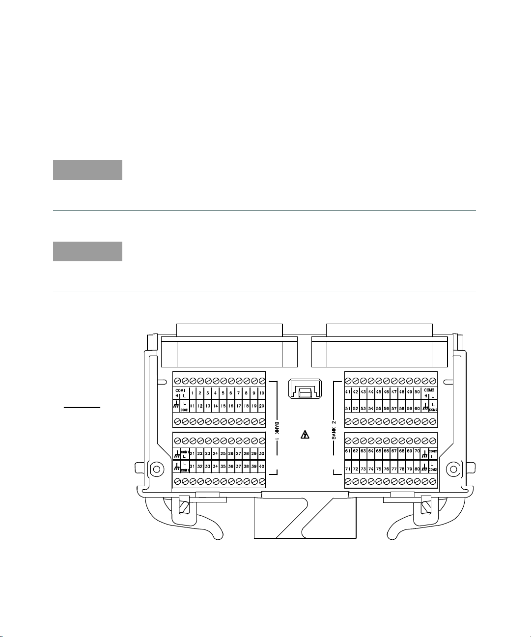
34922A D-Sub Connectors
For orientation, the D-sub connector
end of the module is facing you.
Bank 2
Bank 1
10H6H 6L 1H 1L 7H 7L
COM
1L 3H 3L 9H 9L 4H 4L
COM
1H2H 2L 10L 5L5H
1 2 3 4 5 6 7 8 9 1011121314151617
18
19
20
12H16H 16L 11H 11L 17H 17L 12L 8H 8 L 34H 34L 19H 19L 14H 14L 20H 20L Interlock1
21
22 23
24 25
26
27
28 29
30 31
32 33 34 35
36
37
38 39
GND 26H 26L 21H 21L 22H 22L 27H 27L 13H 13L 28H 28L 24H 24L 29H 29L 1 5H 15L Interlock 1
40
41
42 43
44
45 46
47
48
49 50 51
52
53 54 55
56
57 5958
60
61 62
63 64
65
66
67 68
69 70
71 72 73 74
75
76
77 78
GND 32H 3 2L 31H 31L 33H 33L 18H 18L 23H 23L 35H 35L 30H 30L 25H 25L
NC NC
78-Pin D-Sub
Male Connector
Bank 1
Description Pin Description Pin Description Pin Description Pin Description Pin Description Pin
1H 3 8H 29 15H 57 22H 45 29H 55 COM1 H 9
1L 4 8L 30 15L 58 22L 46 29L 56 COM1 L 10
2H 7 9H 13 16H 21 23H 69 30H 73 Interlock 1 39
2L 8 9L 14 16L 22 23L 70 30L 74 Interlock 1 59
3H 11 10H 17 17H 25 24H 53 31H 63 GND 40
3L 12 10L 18 17L 26 24L 54 31L 64 GND 60
4H 15 11H 23 18H 67 25H 75 32H 61 No Connect 77
4L 16 11L 24 18L 68 25L 76 32L 62 No Connect 78
5H 19 12H 27 19H 33 26H 41 33H 65
5L 20 12L 28 19L 34 26L 42 33L 66
6H 1 13H 49 20H 37 27H 47 34H 31
6L 2 13L 50 20L 38 27L 48 34L 32
7H 5 14H 35 21H 43 28H 51 35H 71
7L 6 14L 36 21L 44 28L 52 35L 72
26 Keysight 34921A-34925A User’s Guide

WARNING
As a safety feature, interlock 1 pins (39 and 59) on Bank 1 must be shorted to
For orientation, the D-sub connector
end of the module is facing you.
Bank 2
Bank 1
45H41H 41L 36H 36L 42H 42L
COM
2L 38H 38L 44H 44L 39H 39L
COM
2H37H 37L 45L 40L40H
1 2 3 4 5 6 7 8 9 1011121314151617
18
19
20
47H51H 51L 46H 46L 52H 52L 47L 43H 43L 69H 69L 54H 54L 49H 49L 55H 55L Interlock 2
21
22 23
24 25
26
27
28 2 9
30 31
32 33 34 35
36
37
38 39
GND 61H 61L 56H 56L 57H 57L 62H 62L 48H 48L 63H 63L 59H 59L 64H 64L 50H 50L Interlock 2
40
41
42 43
44
45 46
47
48
49 50 51
52
53 54 55
56
57 5958
60
61 62
63 64
65
66
67 6 8
69 70
71 72 73 74
75
76
77 78
GND 67H 67L 66H 66L 68H 68L 53H 53L 58H 58L 70H 70L 65H 65L 60H 60L
NC NC
78-Pin D-Sub
Male Connector
enable the Bank 1 Analog Bus relays to close. The optional 34922T terminal
blocks short these pins for you. This feature protects inadvertent routing of
high voltages from the Analog Buses to the D-sub connector of the module.
Bank 2
Description Pin Description Pin Description Pin Description Pin Description Pin Description Pin
36H 3 43H 29 50H 57 57H 45 64H 55 COM2 H 9
36L 4 43L 30 50L 58 57L 46 64L 56 COM2 L 10
37H 7 44H 13 51H 21 58H 69 65H 73 Interlock 2 39
37L 8 44L 14 51L 22 58L 70 65L 74 Interlock 2 59
38H 11 45H 17 52H 25 59H 53 66H 63 GND 40
38L 12 45L 18 52L 26 59L 54 66L 64 GND 60
39H 15 46H 23 53H 67 60H 75 67H 61 No Connect 77
39L 16 46L 24 53L 68 60L 76 67L 62 No Connect 78
40H 19 47H 27 54H 33 61H 41 68H 65
40L 20 47L 28 54L 34 61L 42 68L 66
Keysight 34921A-34925A User’s Guide 27

Description Pin Description Pin Description Pin Description Pin Description Pin Description Pin
WARNING
NOTE
41H 1 48H 49 55H 37 62H 47 69H 31
41L 2 48L 50 55L 38 62L 48 69L 32
42H 5 49H 35 56H 43 63H 51 70H 71
42L 6 49L 36 56L 44 63L 52 70L 72
As a safety feature, interlock 2 pins (39 and 59) on Bank 2 must be shorted to
enable the Bank 2 Analog Bus relays to close. the optional 34922T terminal
blocks short these pins for you. This feature protects inadvertent routing of
high voltages from the Analog Buses to the D-sub connector of the module.
34922T Terminal Blocks
Two terminal blocks are available to facilitate wiring connections to the 34922A
module:
34922T-001 (Option 001) Terminal block with solder connectors
34922T-002 (Option 002) Terminal block with screw connectors
All modules that connect to the internal DMM are interlock protected. This
means that when an installed module is exposed (no terminal block or cable is
connected), the Analog Bus relays are open and disconnected from the Analog
Buses. See “Safety Interlock” on page 11 for further information.
28 Keysight 34921A-34925A User’s Guide

34922T-001 Terminal Block
W
i
r
e
S
i
z
e
:
2
2
A
W
G
T
y
p
i
c
a
l
2
0
A
W
G
M
a
x
This terminal block with solder-type connections is labeled with the model
number and the abbreviated module name. In addition, space is available on the
label for you to write the slot number.
Keysight 34921A-34925A User’s Guide 29

34922T-002 Terminal Block
B
A
N
K
1
B
A
N
K
2
1
2
3 4 5 COM1
6
7
8 9 10 11
HLHLHLHLHLH
L
HLHLHLHL
HLHL
12
13
14 15 16
17
HLHLHLHL
HLHL
HLHLHLHLHLH
L
18
19
20 21 22 23
24
25
26 27 28
29
HLHLHLHL
HLHL
HLHLHLHLHLH
L
30
31
32 33 34 35
59
60
61 62 63 64
HLHLHLHLHLH
L
HLHLHLHL
HLHL
65
66
67 68 69
70
47
48
49 50 51 52
HLHLHLHLHLH
L
HLHLHLHL
HLHL
53
54
55 56 57
58
COM2
36
37 38 39
40
HLHLHLHL
HLHL
HLHLHLHLHLH
L
41
42
43 44 45 46
W
i
r
e
S
i
z
e
:
2
0
A
W
G
T
y
p
i
c
a
l
1
8
A
W
G
M
a
x
This terminal block with screw-type connections is labeled with the model number
and the abbreviated module name. In addition, space is available on the label for
you to write the slot number.
30 Keysight 34921A-34925A User’s Guide

34923A 40/80-Channel Reed Multiplexer
NOTE
The 34923A 40/80-Channel Reed Multiplexer (40/80-Ch Reed MUX) is divided
into two equal banks of non-latching reed switches. This module also contains
eight armature Analog Bus relays (channels 911-914 and 921-924), four on each
bank that can connect the bank relays to the system Analog Buses. You can
connect any of the channels to the internal DMM through ABus1 and ABus2 for
voltage or resistance measurements.
Using program commands or the mainframe front panel, you can control each of
the channel switches individually, and configure this module for differential
(2-wire or 4-wire) or single-ended (1-wire) mode. Refer to the simplified
schematics on page 34 and page 38.
If you are using an Keysight 34923T-00x terminal block to connect your DUT to this
module, be sure to use the terminal block that corresponds to your module
configuration mode (Refer to the terminal block drawings on page 37 and page 41.):
34923T-001 (Option 001) Terminal block for differential (two- or four-wire) mode
34923T-002 (Option 002) Terminal block for single-ended (1-wire) mode
You can confirm the mode in which your module is configured by using the
SYSTem:CTYPe? <slot number> program command. This command returns the
identity of the plug-in module in the specified slot.
Whenever you change from 2- or 4-wire mode to 1-wire mode, or the reverse,
you must cycle power on the 34980A for the configuration to take effect.
In all modes, this module has capability to scan as many as 500 channels/second
using the internal DMM. With the automatic “break-before-make” connection
operation, you are assured that no two signals are connected to each other during
a scan.
This module is interlock protected, which means whenever the D-sub connector
end of the modules is exposed, the Analog Bus relays immediately open and
disconnect from the Analog Bus. For more information, see “Safety Interlock” on
page 11 and the D-Sub connector drawings on page 35 and page 39.
Keysight 34921A-34925A User’s Guide 31

CAUTION
Because user-attached reactive loads and backplane parasitic capacitance
may result in high in-rush currents, 100
relays from damage and performance degradation. Therefore, you must
consider these resistors when you are designing a measurement. Refer to the
simplified schematics on page 34 and page 38.
Lifetime of relays is severely degraded as current or voltage goes up.
If higher voltage is being switched, limits on source current are recommended.
When the power is off, all channel and Analog Bus relays open.
Two-Wire Mode
You may configure the 34923A as:
– two independent 20-channel 2-wire MUXes. This configuration requires
neither the use of external wiring nor connection through the internal Analog
Buses.
– one 40-channel, 2-wire MUX. For this configuration, you must use external
wiring or connect through the internal Analog Buses.
In 2-wire mode, you can close no more than 20 channels simultaneously due to
power dissipation. These 20 channels are split 10 to a bank. However, note that
Analog Bus relays count half as much as channel relays in that total. For example,
with one Analog Bus relay closed, you can close up to a maximum of 19 channel
relays. If you try to close more than the allowed number of channels, you will
receive an error message.
Ω
in-rush resistors protect the reed
Four-Wire Mode
You may configure the 34923A as a 20-channel 4-wire MUX. This configuration
requires neither external wiring nor connection through the Analog Buses.
For 4-wire resistance measurements, the instrument automatically pairs channel
n on Bank 1 (source) with channel n+20 on Bank 2 (sense) to provide these
connections. Four-wire controls occur only when doing 4-wire measurement
operations through the internal DMM, such as MEASure:FRESistance? or
scanning a channel previously configured as 4-wire.
32 Keysight 34921A-34925A User’s Guide

One-Wire Mode
NOTE
You may configure the 34923A as:
– two independent 40-channel 1-wire MUXes. This configuration requires
neither external wiring nor connection through the internal Analog Buses.
– one 80-channel 1-wire MUX. You must use external wiring or connect through
the internal Analog Bus for this configuration.
Because all bank relays supply only HI signals, you can apply a LOW signal
through COM1 L or COM2 L when you are making 2-wire resistance
measurements in 1-wire mode.
In 1-wire mode, you can close no more than 40 channels simultaneously due to
power dissipation. These channels are split 20 to a bank. For example, with one
Analog Bus relay closed you can close up to a maximum of 39 channel relays. If
you try to close more than the allowed number of channels, you will receive an
error message.
Keysight 34921A-34925A User’s Guide 33

34923A Simplified Schematic for Two- or Four-Wire Mode
HL
HL
026
027
028
029
030
031
032
033
034
035
036
037
038
039
040
021
022
023
024
025
001
002
003
004
005
006
007
008
009
010
011
012
013
014
015
016
017
018
019
020
H
L
H
L
H
L
H
L
ABus 2
DMM
(SENS)
ABus 3
ABus 4
923
913 914
924922
912911
921
ABus1
DMM
(MEAS)
HL HL H L H L
L
H
L
H
L
H
L
H
L
HL
L
H
LHLHLHLH
HL
HL
HL H L
H
LH
100Ω 100Ω
100Ω
100Ω
100Ω
100Ω
100Ω
100Ω
100Ω
100Ω
100Ω 100Ω
Bank 1
Bank 2
COM 1
COM 2
Analog Buses
NOTE: The three-digit number assigned to each switch represents the channel number.
NOTE:
Bank Relays: Reed non-latching
Analog Bus Relays: Armature
non-latching
This drawing shows two independent 20-channel 2-wire MUXes. To change
configuration modes, use the SYSTem:MODule:WIRE:MODE command.
34 Keysight 34921A-34925A User’s Guide

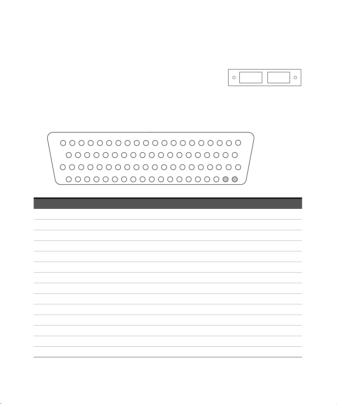
34923A D-Sub Connectors for Two- or Four-Wire Mode
For orientation, the D-sub connector
end of the module is facing you.
Bank 2
Bank 1
17L
18
19 20
21 22
23
24
25 26
27 28
29 30 31 32
33
Reserved 11H 11L 7H 7L 17H 13H 13L 9H 9L 19H 19L 15H 15L Int erlock 1
1 2 3 4 5 6 7 8 9 1011 1213141516 17
Interlock11H 1L 2H 2L 3H 3L
COM1HCOM
1L
4H 4L 14H 14L 5H 5L 20H 20L
GND 6H 6L 16H 16L 12H 12L 8H 8L 18H 18L 10H 10L
Reserved
34
35
36 37
38
39 40
41
42
43 44 45
46
47 48 49
50
50-Pin D-Sub
Male Connector
Bank 1
Description Pin Description Pin Description Pin Description Pin Description Pin
1H 1 6H 35 11H 19 16H 37 COM1 H 7
1L 2 6L 36 11L 20 16L 38 COM1 L 8
2H 3 7H 21 12H 39 17H 23 Interlock 1 17
2L 4 7L 22 12L 40 17L 24 Interlock 1 33
3H 5 8H 41 13H 25 18H 43 GND 34
3L 6 8L 42 13L 26 18L 44 Reserved 18
4H 9 9H 27 14H 11 19H 29 Reserved 47
4L 10 9L 28 14L 12 19L 30 Reserved 48
5H 13 10H 45 15H 31 20H 15 Reserved 49
5L 14 10L 46 15L 32 20L 16 Reserved 50
Keysight 34921A-34925A User’s Guide 35

WARNING
As a safety feature, interlock 1 pins (17 and 33) on Bank 1 must be shorted to
37L
18 19
20
21
22
23 24 25 26 27 2 8 29 30 31 32 33
Reserved 31H 31L 27H 27L 37H 33H 33L 29H 29L 39H 39L 35H 35L Interlock 2
1234567891011121314151617
23L Interloc k 221H 21L 22H 22L 23H
COM2HCOM
2L
24H 24L 34H 34L 25H 25L 40H 40L
Reserved
34 35 36 37 38 39 40 41 42 43 44 45 46
47
48 49 50
GND 26H 26L 36H 36L 32H 32L 28H 28L 38H 38L 30H 30L
50-Pin D-Sub
Male Connector
WARNING
enable the Bank 1 Analog Bus relays to close. The optional 34923T-001 (for
2-wire) terminal block shorts these pins for you. This feature protects
inadvertent routing of high voltages from the Analog Bus to the D-sub
connector of the module.
Bank 2
Description Pin Description Pin Description Pin Description Pin Description Pin
21H 1 26H 35 31H 19 36H 37 COM2 H 7
21L 2 26L 36 31L 20 36L 38 COM2 L 8
22H 3 27H 21 32H 39 37H 23 Interlock 2 17
22L 4 27L 22 32L 40 37L 24 Interlock 2 33
23H 5 28H 41 33H 25 38H 43 GND 34
23L 6 28L 42 33L 26 38L 44 Reserved 18
24H 9 29H 27 34H 11 39H 29 Reserved 47
24L 10 29L 28 34L 12 39L 30 Reserved 48
25H 13 30H 45 35H 31 40H 15 Reserved 49
25L 14 30L 46 35L 32 40L 16 Reserved 50
As a safety feature, interlock 2 pins (17 and 33) on Bank 2 must be shorted to
enable the Bank 2 Analog Bus relays to close. The optional 34923T-001 (for
2-wire) shorts these pins for you. This feature protects inadvertent routing of
high voltages from the Analog Buses to the D-sub connector of the module.
36 Keysight 34921A-34925A User’s Guide

34923T-001 Terminal Block for Two-Wire or Four-Wire Mode
NOTE
NOTE
W
i
r
e
S
i
z
e
:
2
0
A
W
G
T
y
p
i
c
a
l
1
8
A
W
G
M
a
x
This terminal block with screw-type connections is labeled with the model number
and the abbreviated module name. In addition, space is available on the label for
you to write the slot number.
All modules that connect to the internal DMM are interlock protected. This
means that when an installed module is exposed (no terminal block or cable is
connected), the Analog Bus relays are open and disconnected from the Analog
Buses. See “Safety Interlock” on page 11 for further information.
If you are using an Keysight terminal block to connect your DUT to this module
be sure to use the 34923T-001 terminal block that corresponds to the 2- or
4-wire configuration mode. An error will not be generated if you have installed a
terminal block that doesn't match the present module configuration.
Keysight 34921A-34925A User’s Guide 37

34923A Simplified Schematic for One-Wire Mode
ABus 2
DMM
(SENS)
ABus3
ABus 4
ABus1
DMM
(MEAS)
HH H H
021
022
023
024
025
026
027
028
029
030
011
012
013
014
015
016
017
018
019
020
031
032
033
034
035
036
037
038
039
040
001
002
003
004
005
006
007
008
009
010
911 912 913 914
921 922 923 924
HL
HL HLHL
HL
071
072
073
074
075
076
077
078
079
080
061
062
063
064
065
066
067
068
069
070
051
052
053
054
055
056
057
058
059
060
041
042
043
044
045
046
047
048
049
050
H
H
H
H
HL
HL HL HL HL
100Ω
100Ω
100Ω
100Ω
100Ω
100Ω
100Ω 100Ω
100Ω
100Ω
100Ω
100Ω
Bank 1
Bank 2
COM 1
COM 2
Analog Buses
NOTE: The three-digit number
assigned to each switch
represents the channel number.
NOTE:
Bank relays: Reed non-latching
Analog Bus relays: Armature non-latching
This drawing shows two independent 40-channel 1-wire MUXes. To change
configuration modes, use the SYSTem:MODule:WIRE:MODE command.
38 Keysight 34921A-34925A User’s Guide

34923A D-Sub Connectors for One-Wire Mode
For orientation, the D-sub connector
end of the module is facing you.
Bank 2Bank 1
34
34
35
36 37
38
39 40
41
42
43 44 45
46
47 48 49
50
18
19 20
21 22
23
24
25 26
27 28
29 30 31 32
33
GND11123132232415 1635361920
Reserv ed
Reserved 21 22 13 14 33 25 26 17 18 37 38 29 30 Interl ock 1
1 2 3 4 5 6 7 8 9 1011121314151617
Interlock1123456
COM
1H
COM
1L
7 8 27 28 9 10 39 40
50-Pin D-Sub
Male Connector
Bank 1
Description Pin Description Pin Description Pin Description Pin Description Pin
1 1 11 35 21 19 31 37 COM1 H 7
2 2 12 36 22 20 31 38 COM1 L 8
3 3 13 21 23 39 33 23 Interlock 1 17
4 4 14 22 24 40 34 24 Interlock 1 33
5 5 15 41 25 25 35 43 GND 34
6 6 16 42 26 26 36 44 Reserved 18
7 9 17 27 27 11 37 29 Reserved 47
8 1018 2828 1238 30Reserved 48
9 1319 4529 3139 15Reserved 49
10 14 20 46 30 32 40 16 Reserved 50
Keysight 34921A-34925A User’s Guide 39

WARNING
As a safety feature, interlock 1 pins (17 and 33) on Bank 1 must be shorted to
74
34
35
36 37
38
39 4 0
41
42
43 44 45
46
47 48 49
50
18
19 20
21 22
23
24
25 26
27 28
29 30 31 32
33
GND515271726364555675 765960
Reserved 61 62 53 54 73 65 66 57 58 77 78 69 70 Inter lock 2
1 2 3 4 5 6 7 8 9 1011 1213 141516 17
Interlock 241 42 43 44 4 5 46
COM2HCOM
2L
47 48 67 68 49 50 79 80
Reser ved
50-Pin D-Sub
Male Connector
WARNING
enable the Bank 1 Analog Bus relays to close. The optional 34923T-002 (for
1-wire) shorts these pins for you. This feature protects inadvertent routing of
high voltages from the Analog Bus to the D-sub connector of the module.
Bank 2
Description Pin Description Pin Description Pin Description Pin Description Pin
411513561197137COM2 H7
422523662207238COM2 L 8
433532163397323Interlock 217
444542264407424Interlock 233
455554165257543GND34
466564266267644Reserved 18
479572767117729Reserved47
48 10 58 28 68 12 78 30 Reserved 48
49 13 59 45 69 31 79 15 Reserved 49
50 14 60 46 70 32 80 16 Reserved 50
As a safety feature, interlock 2 pins (17 and 33) on Bank 2 must be shorted to
enable the Bank 2 Analog Bus relays to close. The optional 34923T-002 (for
1-wire) shorts these pins for you. This feature protects inadvertent routing of
high voltages from the Analog Buses to the D-sub connector of the module.
40 Keysight 34921A-34925A User’s Guide
34923T-002 Terminal Block for One-Wire Mode
NOTE
NOTE
W
i
r
e
S
i
z
e
:
2
0
A
W
G
T
y
p
i
c
a
l
1
8
A
W
G
M
a
x
This terminal block with screw-type connections is labeled with the model number
and the abbreviated module name. In addition, space is available on the label for
you to write the slot number.
All modules that connect to the internal DMM are interlock protected. This
means that when an installed module is exposed (no terminal block or cable is
connected), the Analog Bus relays are open and disconnected from the Analog
Buses. See “Safety Interlock” on page 11 for further information.
If you are using an Keysight terminal block to connect your DUT to this module
be sure to use the 34923T-002 terminal block that corresponds to the 1-wire
configuration mode. An error will not be generated if you have installed a
terminal block that doesn't match the present module configuration.
Keysight 34921A-34925A User’s Guide 41

34924A 70-Channel Reed Multiplexer
The high-density 34924A 70-Channel Reed Multiplexer (70-Ch Reed MUX) is
divided into two banks with 35 non-latching reed switches (channels 1-35 and
36-70) in each. This module also contains eight armature Analog Bus relays
(channels 911-914 and 921-924), four on each bank that can connect the bank
relays to the system Analog Buses. Through ABus1 and ABus2 you can connect
any of the channels to the system DMM for voltage or resistance measurements.
See the simplified schematic on page 43.
Using program commands or the mainframe front panel, you can control each of
the channel switches individually, and thus configure the 34924A in any of these
modes:
– two independent 35-channel 2-wire MUXes. This configuration requires
neither using external wiring nor connecting through the internal Analog
Buses.
– one 70-channel, 2-wire MUX. You must use external wiring or connect through
the internal Analog Buses for this configuration.
– one 35-channel 4-wire MUX. This configuration requires neither using external
wiring nor connecting through the internal Analog Buses. For 4-wire resistance
measurements, the instrument automatically pairs channel n on Bank 1
(source) with channel n+35 on Bank 2 (sense) to provide these connections.
Four-wire controls occur only when doing 4-wire measurement operations
through the internal DMM, such as MEASure:FRESistance? or scanning a
channel previously configured as 4-wire.
In 2-wire mode, you can close no more than 20 channels simultaneously due to
power dissipation. These 20 channels are split 10 to a bank. However, note that
Analog Bus relays count half as much as channel relays in that total. For example,
with one Analog Bus relay closed, you can close up to a maximum of 19 channel
relays. If you try to close more than the allowed number of channels, you will
receive an error message.
In all modes, this module has capability to scan as many as 500 channels/second
using the internal DMM. With the automatic “break-before-make” connection
operation, you are assured that no two signals are connected to each other during
a scan.
42 Keysight 34921A-34925A User’s Guide

CAUTION
Because user-attached reactive loads and backplane parasitic capacitance
may result in high in-rush currents, 100
relays from damage and performance degradation. Therefore, you must
consider these resistors when you are designing a measurement. Refer to the
simplified schematic on page 43.
This module is interlock protected, which means whenever the D-sub connector
end of the modules is exposed, the Analog Bus relays immediately open and
disconnect from the Analog Bus. For more information, see “Safety Interlock” on
page 11.
Lifetime of relays is severely degraded as current or voltage goes up. If higher
voltage is being switched, limits on source current are recommended.
When the power is off, all channel and Analog Bus relays open.
34924A Simplified Schematic
Ω
in-rush resistors protect the reed
Keysight 34921A-34925A User’s Guide 43

This drawing shows two independent 35-channel 2-wire MUXes.
ABus2
DMM
(SENS)
ABus3 ABus4
ABus1
DMM
(MEAS)
911 914912 913
924922 923921
LH
LH
001
002
003
004
005
H
L
006
H
015
016
017
018
019
L
020
021
022
023
024
025
026
H
L
027
028
029
030
031
032
033
H
L
034
008
009
010
011
012
H
L
013
007
035
014
H
L
036
037
038
039
040
041
042
H
L
043
044
045
046
047
048
049
H
L
050
051
052
053
054
055
056
063
H
L
064
065
066
067
068
069
070
057
058
059
060
061
062
H
L
LH
LH
LH
LH
LH
LHLH
LH
100Ω
100Ω
100Ω
100Ω
100Ω 100Ω
100Ω
100Ω
100Ω
100Ω 100Ω
100Ω
Bank 1
Bank 2
COM 2
COM 1
Analog Buses
NOTE: The three-digit number assigned to
each switch represents the channel number.
NOTE:
Bank relays: Reed non-latching
Analog Bus relays: Armature
non-latching
44 Keysight 34921A-34925A User’s Guide
34924A D-Sub Connectors
For orientation, the D-sub connector
end of the module is facing you.
Bank 2
Bank 1
10H6H 6L 1H 1L 7H 7L
COM
1L 3H 3L 9H 9L 4H 4L
COM
1H2H 2L 10L 5L5H
1 2 3 4 5 6 7 8 9 1011 12131415 16 17
18
19
20
12H16H 16H 11L 11H 17H 17L 12L 8H 8L 34H 34L 19H 19H 14H 14L 20H 20L Interlock1
21
22 23
24 25
26
27
28 29
30 31
32 33 34 35
36
37
38 39
GND 26H 26L 21H 21L 22H 22L 27H 27L 13H 13L 28H 28L 24L 24L 29H 29L 15H 15L Interlock 1
40
41
43
44
45 46
47
48
49 50 51
52
53 54 55
56
57 5958
60
61 62
63 64
65
66
67 68
69 70
71 72 73 74
75
76
77 78
GND 32H 32L 31H 31L 33H 33L 18H 18L 23H 23L 35H 35L 30H 30L 25H 25L
NC NC
42
78-Pin D-Sub
Male Connector
Bank 1
Description Pin Description Pin Description Pin Description Pin Description Pin Description Pin
1H 3 8H 29 15H 57 22H 45 29H 55 COM1 H 9
1L 4 8L 30 15L 58 22L 46 29L 56 COM1 L 10
2H 7 9H 13 16H 21 23H 69 30H 73 Interlock 1 39
2L 8 9L 14 16L 22 23L 70 30L 74 Interlock 1 59
3H 11 10H 17 17H 25 24H 53 31H 63 GND 40
3L 12 10L 18 17L 26 24L 54 31L 64 GND 60
4H 15 11H 23 18H 67 25H 75 32H 61 No Connect 77
4L 16 11L 24 18L 68 25L 76 32L 62 No Connect 78
5H 19 12H 27 19H 33 26H 41 33H 65
5L 20 12L 28 19L 34 26L 42 33L 66
6H 1 13H 49 20H 37 27H 47 34H 31
6L 2 13L 50 20L 38 27L 48 34L 32
7H 5 14H 35 21H 43 28H 51 35H 71
7L 6 14L 36 21L 44 28L 52 35L 72
Keysight 34921A-34925A User’s Guide 45

WARNING
As a safety feature, interlock 1 pins (39 and 59) on Bank 1 must be shorted to
For orientation, the D-sub connector
end of the module is facing you.
Bank 2
Bank 1
45H41H 41L 36H 36L 42H 42L
COM
2L 38H 38L 44H 44L 39H 39L
COM
2H37H 37L 45L 40L40H
1 2 3 4 5 6 7 8 9 1011 12131415 16 17
18
19
20
47H51H 51L 46H 46L 52H 52L 47L 43H 43L 69H 69L 54H 54L 49H 49L 55H 55L Interlock 2
21
22 23
24 25
26
27
28 29
30 31
32 33 34 35
36
37
38 39
GND 61H 61L 56H 56L 57H 57L 62H 62L 48H 48L 63H 63L 59H 59L 64H 64L 50H 50L Interlock 2
40
41
42 43
44
45 46
47
48
49 50 51
52
53 54 55
56
57 5958
60
61 62
63 64
65
66
67 68
69 70
71 72 73 74
75
76
77 78
GND 67H 67L 66H 66L 68H 68L 53H 53L 58H 58L 70H 70L 65H 65L 60H 60L
NC NC
78-Pin D-Sub
Male Connector
enable the Bank 1 Analog Bus relays to close. The optional 34924T terminal
blocks short these pins for you. This feature protects inadvertent routing of
high voltages from the Analog Buses to the D-sub connector of the module.
Bank 2
Description Pin Description Pin Description Pin Description Pin Description Pin Description Pin
36H 3 43H 29 50H 57 57H 45 64H 55 COM2 H 9
36L 4 43L 30 50L 58 57L 46 64L 56 COM2 L 10
37H 7 44H 13 51H 21 58H 69 65H 73 Interlock 2 39
37L 8 44L 14 51L 22 58L 70 65L 74 Interlock 2 59
38H 11 45H 17 52H 25 59H 53 66H 63 GND 40
38L 12 45L 18 52L 26 59L 54 66L 64 GND 60
39H 15 46H 23 53H 67 60H 75 67H 61 No Connect 77
39L 16 46L 24 53L 68 60L 76 67L 62 No Connect 78
40H 19 47H 27 54H 33 61H 41 68H 65
40L 20 47L 28 54L 34 61L 42 68L 66
46 Keysight 34921A-34925A User’s Guide

Description Pin Description Pin Description Pin Description Pin Description Pin Description Pin
WARNING
NOTE
41H 1 48H 49 55H 37 62H 47 69H 31
41L 2 48L 50 55L 38 62L 48 69L 32
42H 5 49H 35 56H 43 63H 51 70H 71
42L 6 49L 36 56L 44 63L 52 70L 72
As a safety feature, interlock 2 pins (39 and 59) on Bank 2 must be shorted to
enable the Bank 2 Analog Bus relays to close. The optional 34924T terminal
blocks short these pins for you. This feature protects inadvertent routing of
high voltages from the Analog Buses to the D-sub connector of the module.
34924T Terminal Blocks
Two terminal blocks are available to facilitate wiring connections to the 34924A
module:
34924T-001 (Option 001) Terminal block with solder connectors
34924T-002 (Option 002) Terminal block with screw connectors
Keysight 34921A-34925A User’s Guide 47
All modules that connect to the internal DMM are interlock protected. This
means that when an installed module is exposed (no terminal block or cable is
connected), the Analog Bus relays are open and disconnected from the Analog
Buses. See “Safety Interlock” on page 11 for further information.

34924T-001 Terminal Block
W
i
r
e
S
i
z
e
:
2
2
A
W
G
T
y
p
i
c
a
l
2
0
A
W
G
M
a
x
This terminal block with solder-type connections is labeled with the model
number and the abbreviated module name. In addition, space is available on the
label for you to write the slot number.
48 Keysight 34921A-34925A User’s Guide

34924T-002 Terminal Block
B
A
N
K
1
B
A
N
K
2
1
2
3 4 5 COM1
6
7
8 9 10 11
HLHLHLHLHLH
L
HLHLHLHL
HLHL
12
13
14 15 16
17
HLHLHLHL
HLHL
HLHLHLHLHLH
L
18
19
20 21 22 23
24
25
26 27 28
29
HLHLHLHL
HLHL
HLHLHLHLHLH
L
30
31
32 33 34 35
59
60
61 62 63 64
HLHLHLHLHLH
L
HLHLHLHL
HLHL
65
66
67 68 69
70
47
48
49 50 51 52
HLHLHLHLHLH
L
HLHLHLHL
HLHL
53
54
55 56 57
58
COM2
36
37 38 39
40
HLHLHLHL
HLHL
HLHLHLHLHLH
L
41
42
43 44 45 46
W
i
r
e
S
i
z
e
:
2
0
A
W
G
T
y
p
i
c
a
l
1
8
A
W
G
M
a
x
This terminal block with screw-type connections is labeled with the model number
and the abbreviated module name. In addition, space is available on the label for
you to write the slot number.
Keysight 34921A-34925A User’s Guide 49

34925A 40/80-Channel Optically-Isolated FET Multiplexer
NOTE
The 34925A 40/80-Channel Optically-Isolated FET Multiplexer (40/80-Ch FET
MUX) module is a high-speed and high-density FET MUX for high throughput
production test. This module is divided into two equal banks of non-latching FET
switches. This module also contains four armature Analog Bus relays. Through
ABus1 and ABus2 you can connect any of the channels to the internal DMM for
voltage or resistance measurements. When the power is off, all channel and
Analog Bus relays open.
Using program commands or the mainframe front panel, you can control each of
the FET channel switches individually, and configure this module for differential
(2-wire or 4-wire) or single-ended (1-wire) mode. Refer to the simplified
schematics on page 53 and page 58.
If you are using an Keysight 34925T-00x terminal block to connect your DUT to
this module, be sure to use the terminal block that corresponds to your module
configuration mode (Refer to the terminal block drawings on page 57 and
page 62):
34925T-001 (Option 001) Terminal block for differential (two- or four-wire) mode
34925T-002 (Option 002) Terminal block for single-ended (1-wire) mode
You can confirm the mode in which your module is configured by using the
SYSTem:CTYPe? <slot number> program command. This command returns the
identity of the plug-in module in the specified slot.
Whenever you change from 2- or 4-wire mode to 1-wire mode, or the reverse,
you must cycle power on the 34980A for the configuration to take effect.
Two-Wire Mode
– two independent 20-channel 2-wire MUXes. This configuration requires
neither using external wiring nor connecting through the internal Analog Bus
relays.
50 Keysight 34921A-34925A User’s Guide

– one 40-channel, 2-wire MUX. You must use external wiring or connect through
NOTE
the Analog Bus relays to for this configuration.
Four-Wire Mode
– You may configure the 34925A as a single 20-channel 4-wire MUX. This
configuration requires using neither external wiring nor connecting through the
internal Analog Buses. For 4-wire resistance measurements, the instrument
automatically pairs channel n on Bank 1 (source) with channel n+20 on Bank 2
(sense) to provide these connections. Four-wire controls occur only when
doing 4-wire measurement operations through the internal DMM, such as
MEASure:FRESistance? or scanning a channel previously configured as
4-wire.
One-Wire Mode
– two independent 40-channel 1-wire MUXes. This configuration requires
neither using external wiring nor connecting through the Analog Bus relays.
– one 80-channel 1-wire MUX. You must use external wiring or connect through
the Analog Bus relays for this configuration.
Because all bank relays supply only HI signals, you can apply a LOW signal
through COM1 L or COM2 L when you are making 2-wire resistance
measurements in 1-wire mode.
Interlock Protection
This module is interlock protected, which means whenever the D-sub connector
end of the modules is exposed, the Analog Bus relays immediately open and
disconnect from the Analog Buses. For more information, see “Safety Interlock” on
page 11.
Keysight 34921A-34925A User’s Guide 51

Overvoltage Protection
This module also features high voltage detection (< 100 V) and current limiting
circuitry to protect the FET relays. This circuitry senses current flows from input
overvoltages. These overvoltages may come from either the MUX input or from
the Analog Buses. In addition, each channel is also protected from input
overvoltages with a resistor.
When overvoltage is detected, all relays (Analog Bus and FET) are opened. While
in the overvoltage state, any attempts to close any Analog Bus or FET switch,
results in an error status response from the module.
Once in the overvoltage state, you must restore normal module operation with
one of these actions:
–using the SYSTem:CPON <slot> command. This affects only the module
specified.
–using the *RST command. This command resets the mainframe and all
installed modules to the Factory configuration. This affects all installed
modules.
– cycling system power. This affects all installed modules.
If the overvoltage situation is not resolved, clearing the overvoltage will result in a
new overvoltage event occurring immediately.
Further FET protection is assured only as one channel in each bank is closed at
any time. Thus this module will operate as only a 1:N MUX module. For more
information about FET channel closures, refer to page 13.
52 Keysight 34921A-34925A User’s Guide

34925A Simplified Schematic for Two- or Four-Wire Mode
Keysight 34921A-34925A User’s Guide 53

This drawing shows two independent 20-channel 2-wire MUXes. To change
026
027
028
029
030
031
032
033
034
035
036
037
038
039
040
021
022
023
024
025
001
002
003
004
005
006
007
008
009
010
011
012
013
014
015
016
017
018
019
020
H
L
H
L
H
L
H
L
ABus 2
DMM
(SENS)
ABus 3
ABus 4
923
913 914
924922
912911
921
ABus 1
DMM
(MEAS)
H
L
H
L
H
L
H
L
LH
LH
LHLHLHLH
LHLHLHLH
Bank 1
Bank 2
COM 1
COM 2
Analog Buses
Overvoltage Protection
(each channel)
100Ω
H
L
51.1Ω
11Ω 11Ω
100Ω
Current-Limiting Circuitry
100Ω
NOTE: The three-digit number assigned to
each switch represents the channel number.
NOTE:
Bank relays: FET non-latching
Analog Bus relays: Armature non-latching
configuration modes, use the SYSTem:MODule:WIRE:MODE command.
54 Keysight 34921A-34925A User’s Guide
34925A D-Sub Connectors for Two- or Four-Wire Mode

Bank 1
For orientation, the D-sub connector
end of the module is facing you.
Bank 1
Bank 2
17L
34
35
36 37
38
39 40
41
42
43 44 45
46
47 48 49
50
18
19 20
21 22
23
24
25 26
27 28
29 30 31 32
33
GND 6H 6L 16H 16L 12H 1 2L 8H 8L 18H 18L 10H 10L
NC NC NC NC
Reserved 11H 11L 7H 7L 17 H 13H 13L 9H 9L 19H 19L 15H 15L Int erlock 1
1 2 3 4 5 6 7 8 9 10111213 1415 1617
Interlock11H 1L 2H 2L 3H 3L
COM1HCOM
1L
4H 4L 14H 14L 5H 5L 20H 20L
50-Pin D-Sub
Male Connector
WARNING
Description Pin Description Pin Description Pin Description Pin Description Pin
1H 1 6H 35 11H 19 16H 37 COM1 H 7
1L 2 6L 36 11L 20 16L 38 COM1 L 8
2H 3 7H 21 12H 39 17H 23 Interlock 1 17
2L 4 7L 22 12L 40 17L 24 Interlock 1 33
3H 5 8H 41 13H 25 18H 43 Reserved 18
3L 6 8L 42 13L 26 18L 44 GND 34
4H 9 9H 27 14H 11 19H 29 No Connect 47
4L 10 9L 28 14L 12 19L 30 No Connect 48
5H 13 10H 45 15H 31 20H 15 No Connect 49
5L 14 10L 46 15L 32 20L 16 No Connect 50
As a safety feature, interlock 1 pins (17 and 33) on Bank 1 must be shorted to
enable the Bank 1 Analog Bus relays to close. The optional 34925T-001 (for
2-wire) terminal block shorts these pins for you. This feature protects
inadvertent routing of high voltages from the Analog Bus to the D-sub
connector of the module.
Keysight 34921A-34925A User’s Guide 55
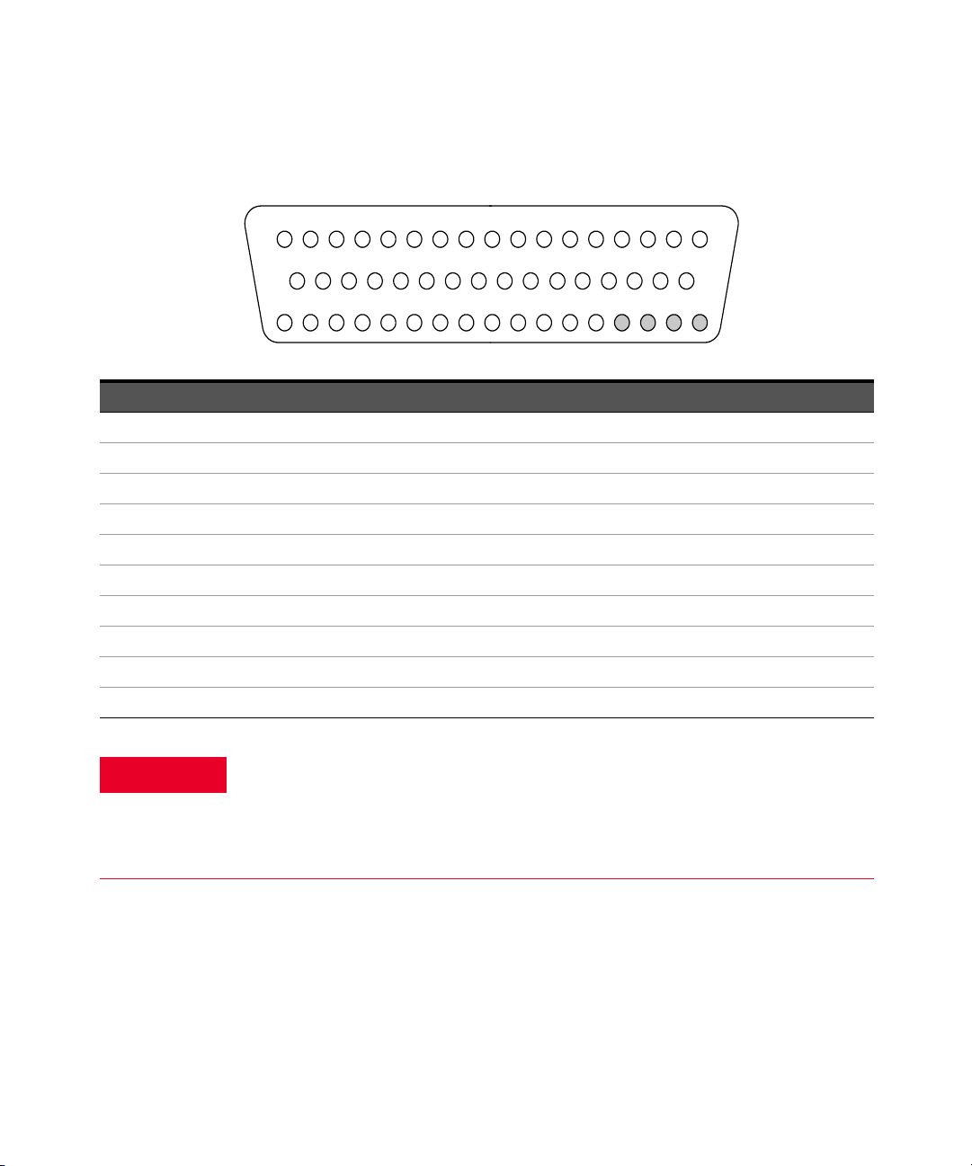
Bank 2
34 35 36 37 38 39 40 41 42 43 44 45 46
47
48 49 50
GND 26H 26L 36H 36L 32H 32L 28H 28L 38H 38L 30H 30L
NC NC NC NC
37L
18 19
20
21
22
23 24 25 26 27 28 29 30 31 32 33
Reserved 31H 31L 27H 27L 37H 33H 33L 29H 29L 39H 39L 35H 35L Interlock 2
1234567891011121314151617
23L Interlock 221H 21L 22H 22L 23H
COM2HCOM
2L
24H 24L 34H 34L 25H 25L 40H 40L
50-Pin D-Sub
Male Connector
WARNING
Description Pin Description Pin Description Pin Description Pin Description Pin
21H 1 26H 35 31H 19 36H 37 COM2 H 7
21L 2 26L 36 31L 20 36L 38 COM2 L 8
22H 3 27H 21 32H 39 37H 23 Interlock 2 17
22L 4 27L 22 32L 40 37L 24 Interlock 2 33
23H 5 28H 41 33H 25 38H 43 Reserved 18
23L 6 28L 42 33L 26 38L 44 GND 34
24H 9 29H 27 34H 11 39H 29 No Connect 47
24L 10 29L 28 34L 12 39L 30 No Connect 48
25H 13 30H 45 35H 31 40H 15 No Connect 49
25L 14 30L 46 35L 32 40L 16 No Connect 50
As a safety feature, interlock 2 pins (17 and 33) on Bank 2 must be shorted to
enable the Bank 2 Analog Bus relays to close. The optional 34925T-001 (for
2-wire) terminal block shorts these pins for you. This feature protects
inadvertent routing of high voltages from the Analog Buses to the D-sub
connector of the module.
56 Keysight 34921A-34925A User’s Guide

34925T-001 Terminal Block for Two-Wire or Four-Wire Mode
NOTE
NOTE
W
i
r
e
S
i
z
e
:
2
0
A
W
G
T
y
p
i
c
a
l
1
8
A
W
G
M
a
x
This terminal block with screw-type connections is labeled with the model number
and the abbreviated module name. In addition, space is available on the label for
you to write the slot number.
All modules that connect to the internal DMM are interlock protected. This
means that when an installed module is exposed (no terminal block or cable is
connected), the Analog Bus relays are open and disconnected from the Analog
Buses. See “Safety Interlock” on page 11 for further information.
If you are using an Keysight terminal block to connect your DUT to this module
be sure to use the 34925T-001 terminal block that corresponds to the 2- or
4-wire configuration mode. An error will not be generated if you have installed a
terminal block that doesn't match the present module configuration.
Keysight 34921A-34925A User’s Guide 57

34925A Simplified Schematic for One-Wire Mode
58 Keysight 34921A-34925A User’s Guide

HH
HHHH
ABus 2
DMM
(SENS)
ABus 3
ABus 4
923
913
914
924922
912
911
921
ABus1
DMM
(MEAS)
001
002
003
004
005
006
007
008
009
010
021
022
023
024
025
026
027
028
029
030
011
012
013
014
015
016
017
018
019
020
031
032
033
034
035
036
037
038
039
040
041
042
043
044
045
046
047
048
049
050
051
052
053
054
055
056
057
058
059
060
061
062
063
064
065
066
067
068
069
070
H
071
072
073
074
075
076
077
078
079
080
H
LHLH
LH
LH
LH
LH
LH
LH
LH
LH
Bank 1
Bank 2
COM 2
COM 1
Analog Buses
Overvoltage Protection
(each channel)
100Ω
H
51.1Ω
11Ω 11Ω
100Ω
Current-Limiting Circuitry
NOTE: The three-digit number assigned to
each switch represents the channel number.
NOTE:
Bank relays: FET non-latching
Analog Bus relays: Armature non-latching
This drawing shows two independent 40-channel, 1-wire MUXes.
To change configuration modes, use the SYSTem:MODule:WIRE:MODE command.
Keysight 34921A-34925A User’s Guide 59

34925A D-Sub Connectors for One-Wired Mode
For orientation, the D-sub connector
end of the module is facing you.
Bank 1
Bank 2
34
34
35
36 37
38
39 40
41
42
43 44 45
46
47 48 49
50
18
19 20
21 22
23
24
25 26
27 28
29 30 31 32
33
GND 11 1 2 31 32 23 24 15 16 35 36 19 20
NC NC NC NC
Reserved 21 22 13 14 33 25 26 17 18 37 38 29 30 Interlock 1
1 2 3 4 5 6 7 8 9 1011121314151617
Interlock1123456
COM1HCOM
1L
7 8 27 28 9 10 39 40
50-Pin D-Sub
Male Connector
WARNING
Bank 1
Description Pin Description Pin Description Pin Description Pin Description Pin
1 1 11 35 21 19 31 37 COM1 H 7
2 2 12 36 22 20 32 38 COM1 L 8
3 3 13 21 23 39 33 23 Interlock 1 17
4 4 14 22 24 40 34 24 Interlock 1 33
5 5 15 41 25 25 35 43 Reserved 18
6 6 16 42 26 26 36 44 GND 34
7 9 17 27 27 11 37 29 No Connect 47
8 1018 2828 1238 30No Connect48
9 1319 4529 3139 15No Connect49
10 14 20 46 30 32 40 16 No Connect 50
As a safety feature, interlock 1 pins (17 and 33) on Bank 1 must be shorted to
enable the Bank 1 Analog Bus relays to close. The optional 34925T-002 (for
1-wire) terminal block shorts these pins for you. This feature protects
inadvertent routing of high voltages from the Analog Bus to the D-sub
connector of the module.
60 Keysight 34921A-34925A User’s Guide

Bank 2
74
34
35
36 37
38
39 40
41
42
43 44 45
46
47 48 49
50
18
19 20
21 22
23
24
25 26
27 28
29 30 31 32
33
GND515271726364555675765960
NC NC NC NC
Reserved 61 62 53 54 73 65 66 57 58 77 78 69 70 I nterlock 2
1 2 3 4 5 6 7 8 9 1011121314151617
Interlock 241 42 43 44 45 46
COM2HCOM
2L
47 48 67 68 49 50 79 80
50-Pin D-Sub
Male Connector
WARNING
Description Pin Description Pin Description Pin Description Pin Description Pin
411513561197137COM2 H 7
422523662207238COM2 L8
433532163397323Interlock 217
444542264407424Interlock 233
455554165257543Reserved 18
466564266267644GND34
479572767117729No Connect47
48 10 58 28 68 12 78 30 No Connect 48
49 13 59 45 69 31 79 15 No Connect 49
50 14 60 46 70 32 80 16 No Connect 50
As a safety feature, interlock 2 pins (17 and 33) on Bank 2 must be shorted to
enable the Bank 2 Analog Bus relays to close. The optional 34925T-002 (for
1-wire) terminal block shorts these pins for you. This feature protects
inadvertent routing of high voltages from the Analog Buses to the D-sub
connector of the module.
Keysight 34921A-34925A User’s Guide 61

34925T-002 Terminal Block for One-Wire Mode
NOTE
NOTE
W
i
r
e
S
i
z
e
:
2
0
A
W
G
T
y
p
i
c
a
l
1
8
A
W
G
M
a
x
This terminal block with screw-type connections is labeled with the model number
and the abbreviated module name. In addition, space is available on the label for
you to write the slot number.
All modules that connect to the internal DMM are interlock protected. This
means that when an installed module is exposed (no terminal block or cable is
connected), the Analog Bus relays are open and disconnected from the Analog
Buses. See “Safety Interlock” on page 11 for further information.
If you are using an Keysight terminal block to connect your DUT to this module
be sure to use the 34925T-002 terminal block that corresponds to the 1-wire
configuration mode. An error will not be generated if you have installed a
terminal block that doesn't match the present module configuration.
62 Keysight 34921A-34925A User’s Guide

Keysight 34921A-34925A User’s Guide 63

THIS PAGE HAS BEEN INTENTIONALLY LEFT BLANK.
64 Keysight 34921A-34925A User’s Guide

Index
Numerics
34921A
connector pinouts
description
external reference
programming examples
simplified schematic
temperature sensor
terminal block
valid measurement
functions, 10
wiring log
34922A
connector pinouts, 26
description
programming examples
simplified schematic
terminal blocks
valid measurement
functions, 10
wiring log
34923A
connector pinouts, 35, 40
description
programming examples
simplified schematic
terminal blocks
valid measurement
functions, 10
wiring log
34924A
connector pinouts, 46
description
programming examples
simplified schematic
terminal blocks
valid measurement
functions, 10
wiring log
34925A
connector pinouts, 55, 60
description
overload protection
,
,
, 37,
,
,
,
,
,
,
17
,
22
24
, 28,
28
31
, 37,
43
, 48,
48
51
,
,
22
42
20
22
,
,
,
22
,
,
30
,
, 34,
42
,
,
50
,
53
19
25
45
programming examples
simplified schematic
terminal blocks
valid measurement
functions, 10
13
wiring log
, 57,
C
connector pinouts
34921A
34922A
34923A
34924A
34925A
13
D
D-sub pinouts
34921A
34922A
34923A
34924A
34925A
E
13
39
external reference, 22
,
20
,
26
, 35,
,
46
, 55,
,
20
,
26
, 35,
,
46
, 55,
F
FET protection, 53
I
13
isothermal block, 22
O
operating considerations, 11
overload protection
overvoltage protection
P
pinouts
, 57,
62
40
60
40
60
,
53
,
,
, 54,
62
53
13
59
34921A
34922A
34923A
34924A
34925A
S
safety notices, 4
T
temperature sensor, 22
terminal block
34921T, 23
34922T Option 001
34922T Option 002
34923T Option 001
34923T Option 002
34924T Option 001
34924T Option 002
34925T Option 001
34925T Option 002
,
20
,
26
, 35,
,
46
, 55,
40
60
,
29
,
30
,
37
,
42
,
49
,
50
,
57
,
62
Keysight 34921A-34925A User’s Guide 65

THIS PAGE HAS BEEN INTENTIONALLY LEFT BLANK.
66 Keysight 34921A-34925A User’s Guide

This information is subject to change
without notice. Always refer to the
Keysight website for the latest
revision.
© Keysight Technologies 2008-2019
Edition 3, July 1, 2019
Printed in Malaysia
*34980-90021*
34980-90021
www.keysight.com
 Loading...