


Installation and User Guide
N4419B, N4420B, N4421B
Multiport Test Sets
This manual provides information for installing Multiport Test Sets for use with
PNA Option 550.
Note: If this Test Set is to be used with PLTS software, please
DO NOT USE THIS MANUAL.
Use the PLTS Installation Guide (N1930-90005) that was shipped with PLTS,
and is also available at www.Agilent.com/find/plts
Manufacturing Part Number: N4421-90002
Printed in USA
Print Date: September 2011
Supersedes: April 2010
© Agilent Technologies, Inc. 2006–2011

WARRANTY STATEMENT
THE MATERIAL CONTAINED IN THIS DOCUMENT IS PROVIDED “AS IS,” AND IS SUBJECT
TO BEING CHANGED, WITHOUT NOTICE, IN FUTURE EDITIONS. FURTHER, TO THE
MAXIMUM EXTENT PERMITTED BY APPLICABLE LAW, AGILENT DISCLAIMS ALL
WARRANTIES, EITHER EXPRESS OR IMPLIED WITH REGARD TO THIS MANUAL AND
ANY INFORMATION CONTAINED HEREIN, INCLUDING BUT NOT LIMITED TO THE
IMPLIED WARRANTIES OF MERCHANTABILITY AND FITNESS FOR A PARTICULAR
PURPOSE. AGILENT SHALL NOT BE LIABLE FOR ERRORS OR FOR INCIDENTAL
OR CONSEQUENTIAL DAMAGES IN CONNECTION WITH THE FURNISHING, USE, OR
PERFORMANCE OF THIS DOCUMENT OR ANY INFORMATION CONTAINED HEREIN.
SHOULD AGILENT AND THE USER HAVE A SEPARATE WRITTEN AGREEMENT WITH
WARRANTY TERMS COVERING THE MATERIAL IN THIS DOCUMENT THAT CONFLICT
WITH THESE TERMS, THE WARRANTY TERMS IN THE SEPARATE AGREEMENT WILL
CONTROL.
DFARS/Restricted Rights Notice
If software is for use in the performance of a U.S. Government prime contract or
subcontract, Software is delivered and licensed as “Commercial computer software” as
defined in DFAR 252.227-7014 (June 1995), or as a “commercial item” as defined in FAR
2.101(a) or as “Restricted computer software” as defined in FAR 52.227-19 (June 1987) or
any equivalent agency regulation or contract clause. Use, duplication or disclosure of
Software is subject to Agilent Technologies’ standard commercial license terms, and
non-DOD Departments and Agencies of the U.S. Government will receive no greater
than Restricted Rights as defined in FAR 52.227-19(c)(1-2) (June 1987). U.S.
Government users will receive no greater than Limited Rights as defined in FAR
52.227-14 (June 1987) or DFAR 252.227-7015 (b)(2) (November 1995), as applicable in
any technical data.
ii

Contacting Agilent Sales and Service Offices
Assistance with test and measurement needs, and information on finding a local Agilent
office, are available on the Internet at: http://www.Agilent.com/find/assist
You can also purchase accessories or documentation items on the Internet at:
http://www.Agilent.com/find/
If you do not have access to the Internet, contact your field engineer.
NOTE In any correspondence or telephone conversation, refer to the product by its
model number and full serial number. with this information, the Agilent
representative can determine whether your unit is still within its warranty
period.
Safety and Regulatory Information
The safety and regulatory information pertaining to this product is located in Chapter 3,
“Safety and Regulatory Information.”
Safety Notes
The following safety notes are used throughout this manual. Familiarize yourself with
each of the notes and its meaning before operating this instrument. All pertinent safety
notes for using this product are located in Chapter 3, “Safety and Regulatory
Information.”
WARNING Warning denotes a hazard. It calls attention to a procedure which,
if not correctly performed or adhered to, could result in injury or
loss of life. Do not proceed beyond a warning note until the
indicated conditions are fully understood and met.
CAUTION Caution denotes a hazard. It calls attention to a procedure that, if not
correctly performed or adhered to, could result in damage to or destruction
of the instrument. Do not proceed beyond a caution sign until the indicated
conditions are fully understood and met.
iii

Documentation Map
PNA Help, embedded in the PNA, offers quick reference to user
documentation, including the capabilities and limitations of Option
550. Click Help on the PNA menu bar or press the Help key on the
PNA front panel.
This Installation Guide helps you to connect the Test Set to the
PNA.
The N4419B, N4420B, N4421B Service Guide, which includes an
Operators Check, is available ONLY at
www.na.tm.agilent.com/multiport
iv

Contents
1Installing the Test Set
Step 1. Verify your Shipment. . . . . . . . . . . . . . . . . . . . . . . . . . . . . . . . . . . . . . . . . . . . . . . . . . .1-3
Step 2. Set Up the PNA . . . . . . . . . . . . . . . . . . . . . . . . . . . . . . . . . . . . . . . . . . . . . . . . . . . . . . .1-6
Step 3. Attach the PNA to the Test Set . . . . . . . . . . . . . . . . . . . . . . . . . . . . . . . . . . . . . . . . . .1-7
Step 4. Install the System on a Bench Top or in an Equipment Rack. . . . . . . . . . . . . . . . . .1-10
Step 5. Make the Interconnections between the Test Set and the PNA . . . . . . . . . . . . . . . .1-16
Step 6. Set Up the General Purpose Interface Bus (GPIB) . . . . . . . . . . . . . . . . . . . . . . . . . .1-22
Step 7. Power up the System . . . . . . . . . . . . . . . . . . . . . . . . . . . . . . . . . . . . . . . . . . . . . . . . . .1-23
Step 8. Perform Quick Check. . . . . . . . . . . . . . . . . . . . . . . . . . . . . . . . . . . . . . . . . . . . . . . . . .1-25
2 Specifications and Characteristics
Definitions . . . . . . . . . . . . . . . . . . . . . . . . . . . . . . . . . . . . . . . . . . . . . . . . . . . . . . . . . . . . . . . . .2-2
General Characteristics . . . . . . . . . . . . . . . . . . . . . . . . . . . . . . . . . . . . . . . . . . . . . . . . . . . . . . .2-3
3 Safety and Regulatory Information
Safety Information . . . . . . . . . . . . . . . . . . . . . . . . . . . . . . . . . . . . . . . . . . . . . . . . . . . . . . . . . . .3-2
Regulatory Information . . . . . . . . . . . . . . . . . . . . . . . . . . . . . . . . . . . . . . . . . . . . . . . . . . . . . . .3-7
Service Guide N5242-90001 Contents-v

Contents
Contents-vi Service Guide N5242-90001

1 Installing the Test Set
1-1

Installing the Test Set
This installation includes the following steps:
1. Verify your Shipment
2. Set Up the PNA
3. Attach the Test Set to the Network Analyzer (N4420B or N4421B Test Set Only)
4. Install the Test Set on a Bench Top or in an Equipment Rack
5. Make the Interconnections between the Test Set and the PNA
6. Set Up the General Purpose Interface Bus (GPIB)
7. Power up the System
8. Perform Quick Check
1-2

Step 1. Verify your Shipment
Step 1. Verify your Shipment
1. Unpack your system from the containers in which it was shipped.
Installing the Test Set
WARNING The test set hardware may be heavy. Use proper lifting techniques.
2. Carefully inspect the test set hardware to make sure that it was not damaged during
shipment.
NOTE If your test set was damaged during shipment, contact Agilent
Tech nol og i es .
1-3
Installing the Test Set
Step 1. Verify your Shipment
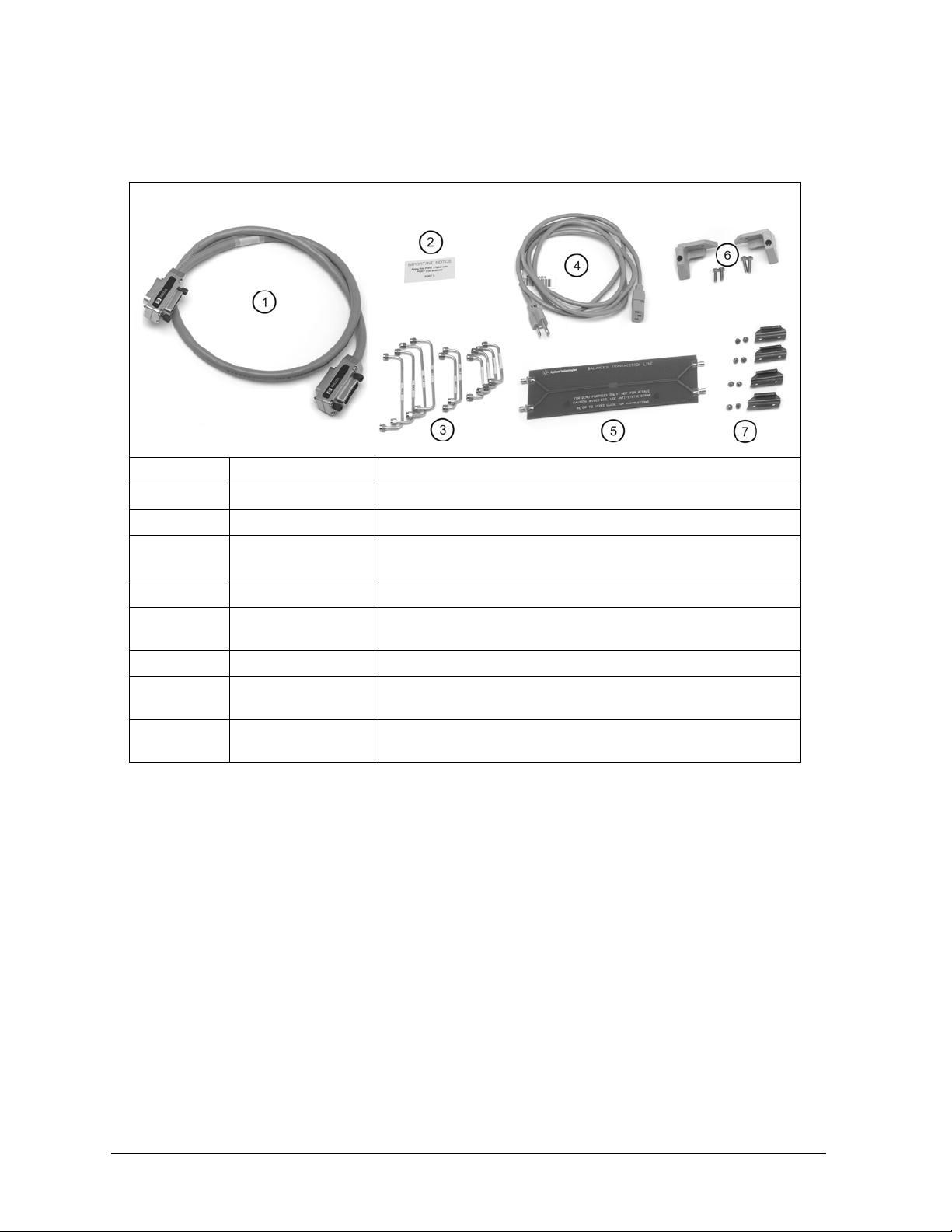
3. Check the accessories that were shipped with your system. Your network analyzer
accessories will be checked during the network analyzer setup.
Item Nr Part Number Part Description
1 8120-3445 GPIB Cable (3 feet)
2 N/A “Port 3” Label
3 Varies by Test Set
Model and Option
Semirigid interconnect cables (refer to Step 5. Make the
Interconnections between the Test Set and the PNA
).
4 Unique to country AC Power Cord (for the test set)
5 AD00658 Balanced Transmission Line PC Board Device (Sample DUT).
Included ONLY when purchased with PLTS system.
6 5023-0132 Rear Locking Feet (for the PNA)
--
(not shown)
7 1600-1423 4 Lock Links (N4420B, N4421B only) with 8 screws
5063-9253 Kit Including Rear Locking Feet (for the Test Set)
(0515-1499)
1-4
Installing the Test Set
Step 1. Verify your Shipment
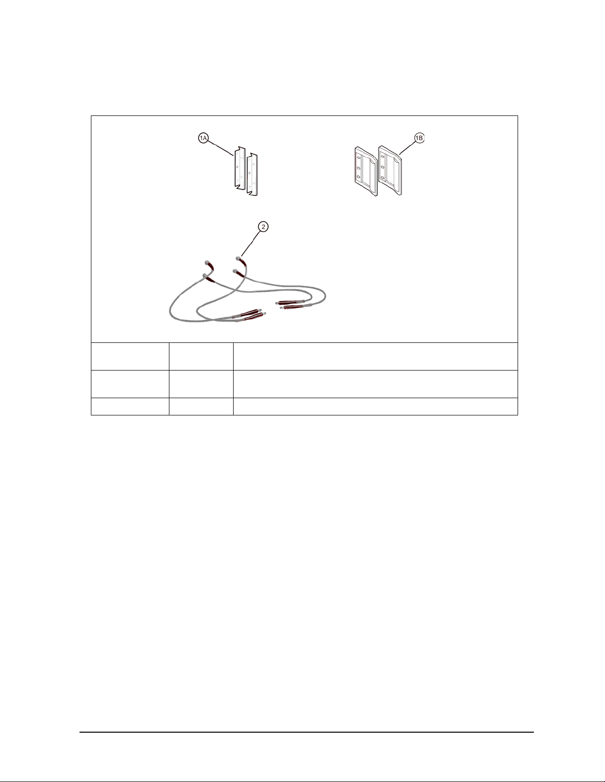
4. If you ordered any of the following options, check the parts. Option 1CP is shipped in
a separate container.
Option
Number
1CP 1A
B20 2 Precision 50-ohm cables (4)
Item
Number
1B
Part Description
Rack mount flange kit (For use with handles)
Handles (set of 2)
1-5
Installing the Test Set
Step 2. Set Up the PNA
Step 2. Set Up the PNA
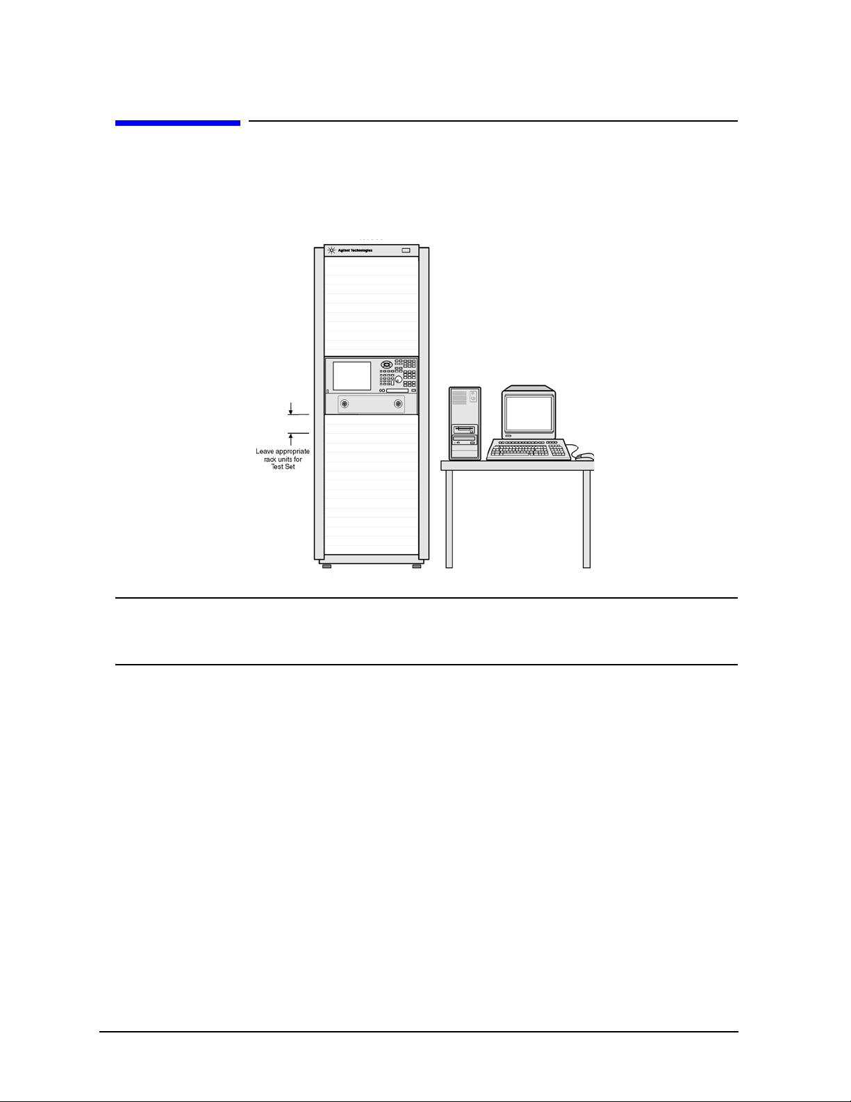
1. Using the PNA Installation and Quick Start Guide, set up the network analyzer.
2. If you are installing your PNA in an equipment rack, be sure to leave at least 2 rack
units of space below the analyzer to install the test set.
NOTE For the N4420B or N4421A/B test set, connect the PNA to the test set
before placing in the rack as a single unit on one set of rails. Refer to“Step
3. Attach the PNA to the Test Set” on page 1-7 for instructions.
1-6
Installing the Test Set
Step 3. Attach the PNA to the Test Set
Step 3. Attach the PNA to the Test Set
(N4420B or N4421B Test Set Only)
If your test set is an N4419B, continue with “Step 4. Install the System on a Bench Top
or in an Equipment Rack” on page 1-11.
The PNA is attached to the N4420B and N4421B test sets using lock links at the front
and locking feet at the rear.
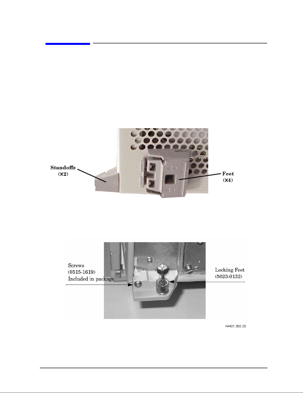
Preparing the PNA
1. Remove the four feet from the bottom of the PNA.
2. Remove the screws from the two lower rear panel standoffs.
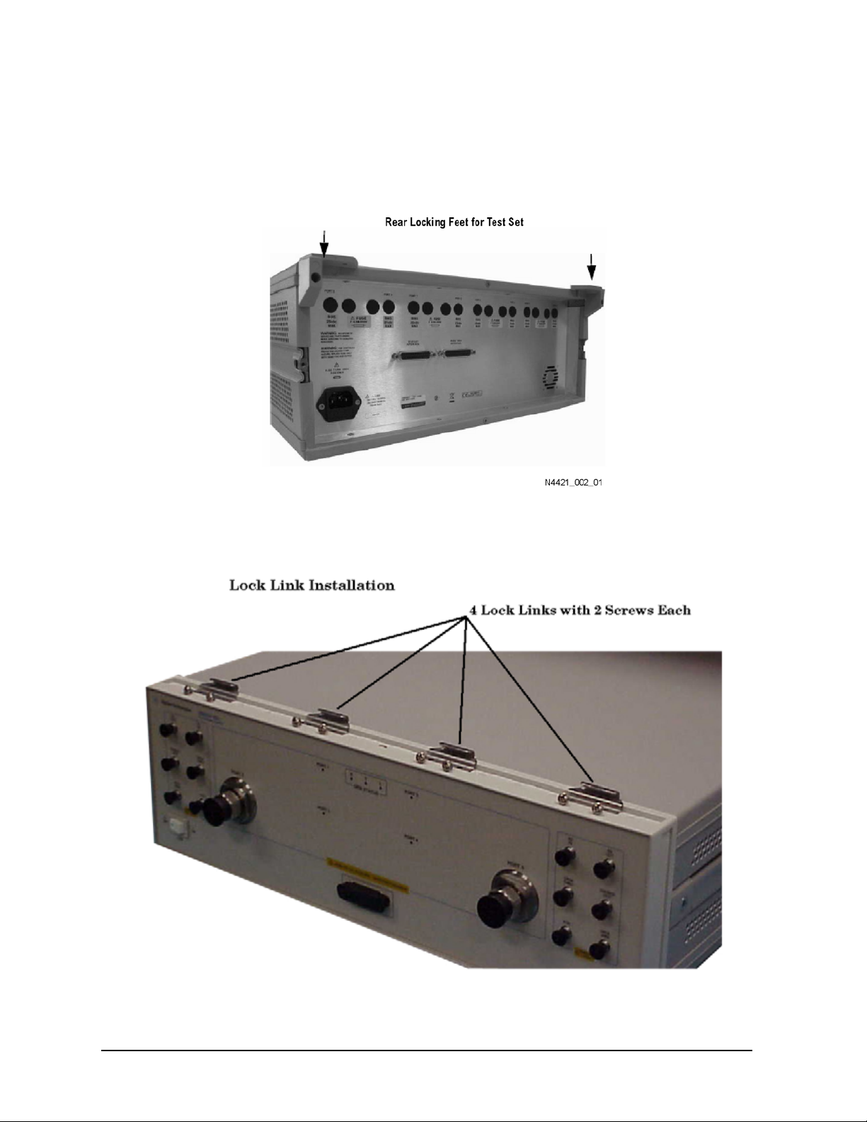
3. Install the two rear locking feet (5023-0132) where the standoffs were removed. The
locking feet may require GENTLE tapping with a hammer to seat properly. Use the
screws (part number 0515-1619) that are included to secure the feet to the PNA.
1-7
Installing the Test Set
Step 3. Attach the PNA to the Test Set
Preparing the Test Set
4. Remove the two standoffs and screws (0515-1619) from the rear panel on the test set.
5. Install the top left and right rear locking feet from the kit (5063-9253) using screws
(0515-1244).
6. Remove the trim strip from the top of the front frame.
7. Install the four lock links from the kit (5063-9253) to the top of the front frame using
eight screws. Refer to the graphic below.
1-8
 Loading...