

Agilent
FieldFox
RF Analyzer
N9912A
Data Sheet

2
Documentation Warranty
THE MATERIAL CONTAINED IN THIS DOCUMENT IS PROVIDED "AS IS," AND IS SUBJECT TO
BEING CHANGED, WITHOUT NOTICE, IN FUTURE EDITIONS. FURTHER, TO THE MAXIMUM
EXTENT PERMITTED BY APPLICABLE LAW, AGILENT DISCLAIMS ALL WARRANTIES,
EITHER EXPRESS OR IMPLIED WITH REGARD TO THIS MANUAL AND ANY INFORMATION
CONTAINED HEREIN, INCLUDING BUT NOT LIMITED TO THE IMPLIED WARRANTIES OF
MERCHANTABILITY AND FITNESS FOR A PARTICULAR PURPOSE. AGILENT SHALL NOT BE
LIABLE FOR ERRORS OR FOR INCIDENTAL OR CONSEQUENTIAL DAMAGES IN
CONNECTION WITH THE FURNISHING, USE, OR PERFORMANCE OF THIS DOCUMENT OR
ANY INFORMATION CONTAINED HEREIN. SHOULD AGILENT AND THE USER HAVE A
SEPARATE WRITTEN AGREEMENT WITH WARRANTY TERMS COVERING THE MATERIAL IN
THIS DOCUMENT THAT CONFLICT WITH THESE TERMS, THE WARRANTY TERMS IN THE
SEPARATE AGREEMENT WILL CONTROL.
DFARS/Restricted Rights Notice
If software is for use in the performance of a U.S. Government prime contract or subcontract, Software is
delivered and licensed as “Commercial computer software” as defined in DFAR 252.227-7014 (June 1995),
or as a “commercial item” as defined in FAR 2.101(a) or as “Restricted computer software” as defined in
FAR 52.227-19 (June 1987) or any equivalent agency regulation or contract clause. Use, duplication or
disclosure of Software is subject to Agilent Technologies’ standard commercial license terms, and nonDOD Departments and Agencies of the U.S. Government will receive no greater than Restricted Rights as
defined in FAR 52.227-19(c)(1-2) (June 1987). U.S. Government users will receive no greater than Limited
Rights as defined in FAR 52.227-14 (June 1987) or DFAR 252.227-7015 (b)(2) (November 1995), as
applicable in any technical data.

3
Table of Contents
Cable and Antenna Analyzer ........................................................... 4
Network Analyzer (Option 303) ...................................................... 8
Spectrum Analyzer (Option 230 and 231) ................................... 13
Preamplifier (Option 235) ............................................................... 21
Interference Analyzer (Option 236) .............................................. 21
Power Meter (Option 302) ............................................................. 21
General Information ........................................................................ 21
Definitions
Specification (spec.)
Warranted performance. Specifications include guardbands to account for the expected statistical performance
distribution, measurement uncertainties, and changes in performance due to environmental conditions. The following
conditions must be met:
FieldFox has been turned on at least 90 minutes
FieldFox is within its calibration cycle
Storage or operation at 25°C ±5 °C range (unless otherwise stated)
Typical (typ.)
Expected performance of an average unit over a 20 °C to 30 °C temperature range after being at ambient temperature
for two hours, unless otherwise indicated; does not include guardbands. It is not covered by the product warranty. The
FieldFox must be within its calibration cycle.
Nominal (nom.)
A general, descriptive term or design parameter. It is not tested, and not covered by the product warranty.
Calibration
The process of measuring known standards to characterize an instrument's systematic (repeatable) errors.
Corrected (residual)
Indicates performance after error correction (calibration). It is determined by the quality of calibration standards and
how well "known" they are, plus system repeatability, stability, and noise.
Uncorrected (raw)
Indicates instrument performance without error correction. The uncorrected performance affects the stability of a
calibration.

4
Cable and Antenna Analyzer
Description
Specification
Typical
Supplemental Information
10 minute
warm up
90 minute
warm up
Frequency Range
Option 104
2 MHz to 4 GHz
Option 106
2 MHz to 6 GHz
Frequency Reference
Accuracy
±2 ppm
±2 ppm
Aging Rate
±1 ppm/yr
±1 ppm/yr
Temperature Stability
±1 ppm over 0 to 55 ºC
±1 ppm
Frequency Resolution
2 MHz to 1.6 GHz
2.5 kHz
> 1.6 GHz to 3.2 GHz
5 kHz
> 3.2 GHz to 6 GHz
10 kHz
Resolution (Number of data points)
101, 201, 401, 601, 801,
1001
Measurement Speed
Return Loss
1.75 GHz – 3.85 GHz,
1001 points, Cal ON
1.5 ms/point (nominal)
DTF
0 to 500 ft, 601
points, Cal ON
2.4 ms/point (nominal)
Output Power (RF Out Port)
High
2 MHz to 4 GHz
< +8 dBm, +6 dBm (nominal)
> 4 GHz to 6 GHz
< +7 dBm, +2 dBm (nominal)
Low (Typically 31 dB below high power)
2 MHz to 4 GHz
< –23 dBm, –25 dBm (nominal)
> 4 GHz to 6 GHz
< –24 dBm, –25 dBm (nominal)
Immunity to Interfering Signals
+16 dBm (nominal)

5
Cable and Antenna Analyzer (continued)
Description
Specification
Typical
10 minute warm up
90 minute warm up
Directivity
Corrected with OSL calibration 1
>42 dB
>42 dB
Corrected with QuickCal (Option 111) 3
≥42 dB
Raw
2 MHz to 3.5 GHz
> 20 dB
> 3.5 GHz to 6 GHz
> 14 dB
Source Match
Corrected with OSL calibration 1
> 36 dB
> 36 dB
Corrected with QuickCal (Option 111) 3
≥35 dB
Raw 2 MHz to 3 GHz
> 25 dB
> 3 GHz to 6 GHz
> 16 dB
Reflection Tracking
Corrected with OSL calibration 1
±0.06 dB
±0.06 dB
Corrected with QuickCal (Option 111)
3
±0.15 dB
Reflection Dynamic Range
Reflection (RF Out port) (High power out)
2 MHz to 4 GHz
60 dB
> 4 GHz to 6 GHz
55 dB
Maximum Measurable Cable Loss Using 1–Port CAT Measurement Model 2
Refl Dyn Range /2
Transmission Dynamic Range(Option 110)
300 Hz IF Bandwidth
2 MHz to 2 GHz
72 dB
> 2 GHz to 3 GHz
67 dB
> 3 GHz to 5 GHz
58 dB
> 5 GHz to 6 GHz
49 dB
Return Loss
Display Range
0 to 100 dB
Resolution
0.01 dB
VSWR
Display Range
1 to 500
Resolution
0.01
Cable Loss
Display Range
0 to 100 dB
Resolution
0.01 dB
6
Cable and Antenna Analyzer (continued)
Description
Specification
Supplemental Information
Distance–to–Fault
Horizontal Range
Range = [(number of points – 1) /
frequency span * 2] * velocity factor *
speed of light
Number of points auto coupled according to start
and stop distance entered
Horizontal
Resolution
Resolution = Range / (number of
points – 1)
Number of points settable by user
Bandpass Mode
Window Types
Maximum, medium, and minimum windows
1
Using recommended calibration kits.
2
Higher cable losses can be measured using transmission or S21 measurements. Cable losses measured in
transmission mode limited by transmission dynamic range.
3
QuickCal is performed with the connect LOAD step.
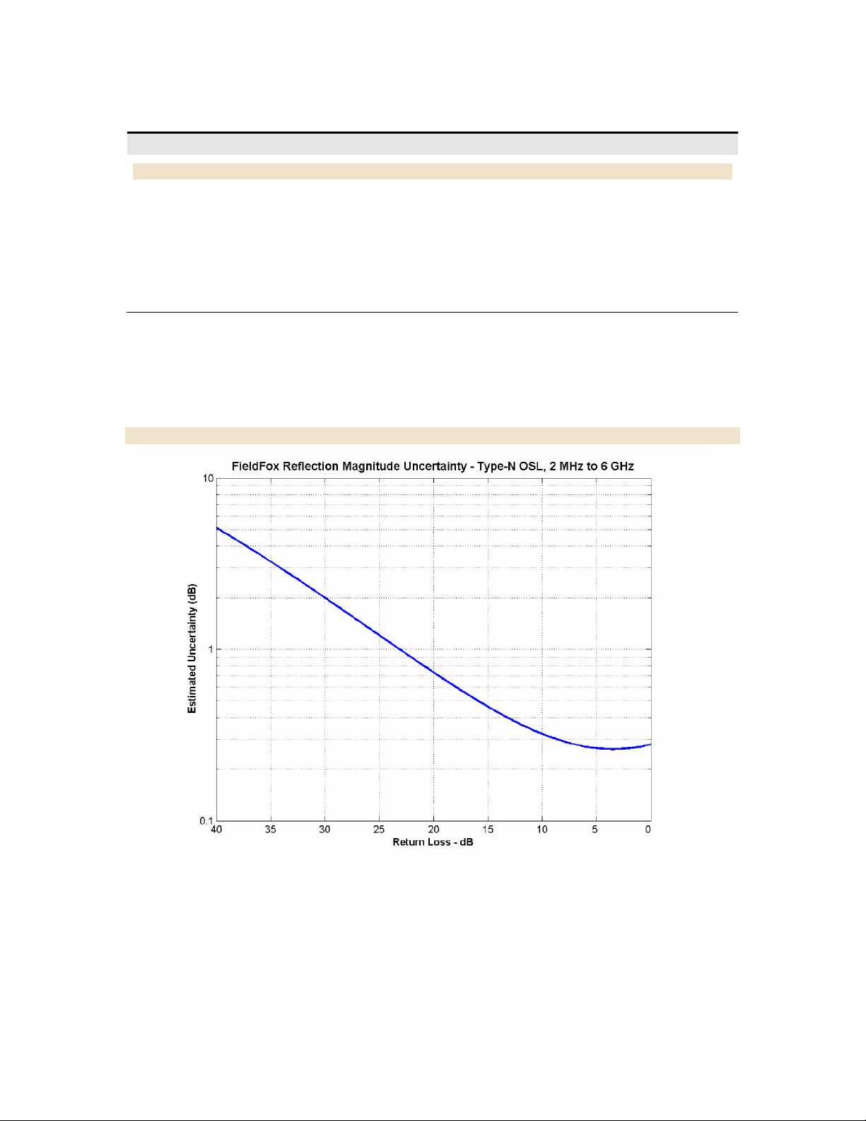
Figure 1: CAT Mode, Type–N Calibration Kit – Magnitude (Specification)
7
Cable and Antenna Analyzer (continued)
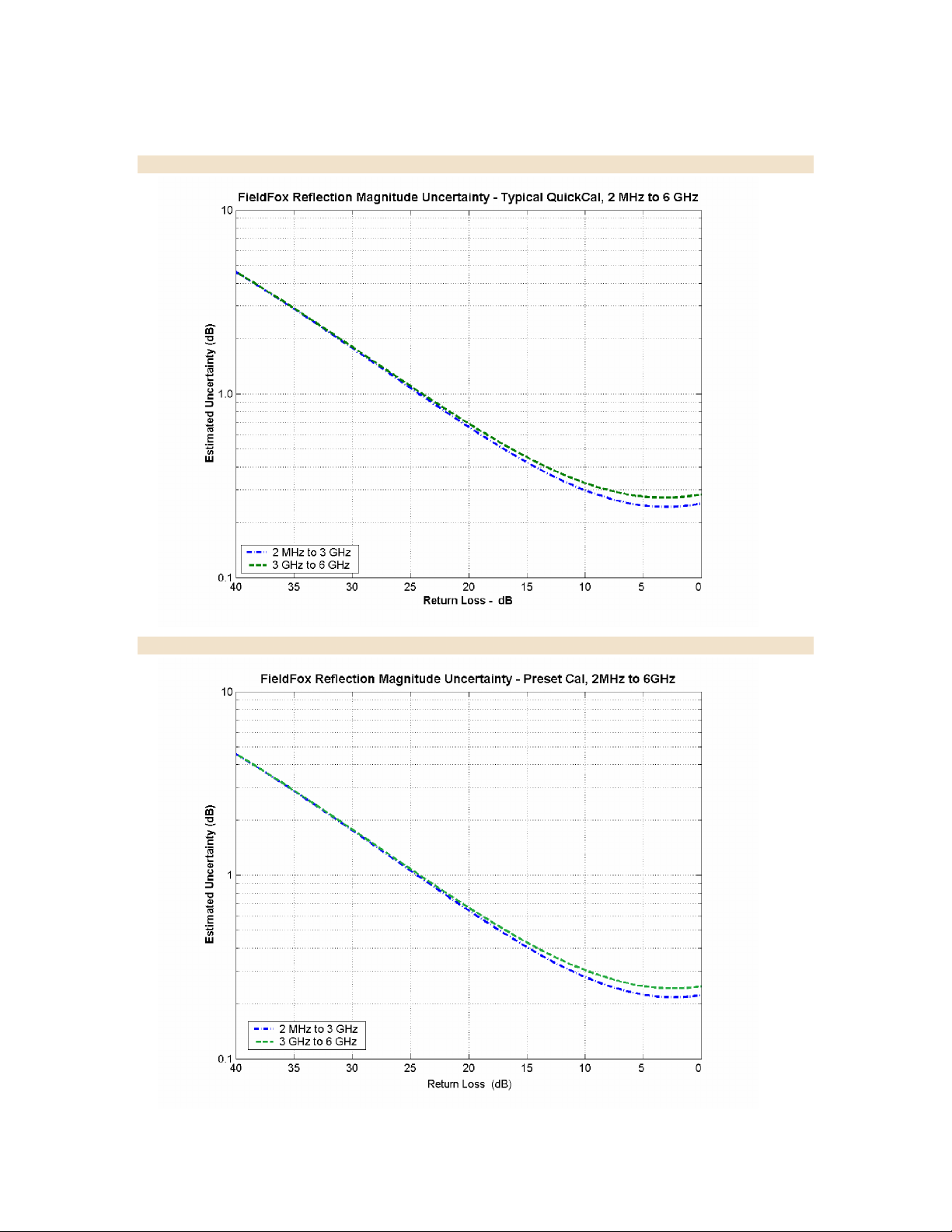
Figure 2: CAT Mode, QuickCal – Magnitude (Typical)
Figure 3: CAT Mode, Preset Cal – Magnitude (Typical)

8
Network Analyzer (Option 303)
Description
Specification
Supplemental Information
Frequency Range
2 MHz to 4 GHz
Option 104
2 MHz to 6 GHz
Option 106
Measurement Speed
S11: 1.75 GHz – 3.85 GHz,
1001 Points, Cal ON
1.5 ms/point (nominal)
S21: 1.78 GHz – 2.06 GHz,
201 Points, Cal ON
1.9 ms/point (nominal)
S11 Phase Uncertainty1
See Figure 5 on
following page
Display Range
–180º to +180º
System Impedance
50Ω (nominal)
75Ω with appropriate adapter and Cal Kit
Description
Information
Measurements
S11 magnitude and phase
S21 magnitude (option 110)
A receiver magnitude
R receiver magnitude
Formats
Log magnitude, Linear magnitude
Available ONLY for S11:
VSWR, Phase, Smith Chart, Polar, Group delay, Unwrapped phase
Resolution
(Number of data points)
101, 201, 401, 601, 801, 1601, 4001, 10001
Custom number of points can be set using SCPI
Averaging
2 to 999
Averages vector data on each successive sweep
Number of traces
Four traces available. Tr1, Tr2, Tr3, Tr4
Data markers
Each trace has six independent markers that can be displayed simultaneously. Delta
markers are available for each marker.
Marker formats
Default marker format is the trace format. In Smith chart or polar format,
[Real +Imag] or [Mag and Phase] formats are also available.
Marker functions
Peak, Next Peak, Peak Left, Peak Right, Mkr→ Center, Min Search, Peak Excursion,
Peak Threshold, Target, Bandwidth, Tracking
Display formats
Single-trace
Dual-trace overlay (both traces on one graticule)
Dual-trace split (each trace on separate graticules)
The following CAT mode performance parameters apply to NA mode: frequency accuracy, frequency resolution, output
power, directivity, source match, reflection tracking, and reflection and transmission dynamic range. NA mode
performance that is in addition to CAT mode is listed in the table below.
1
Using recommended calibration kits.
 Loading...