

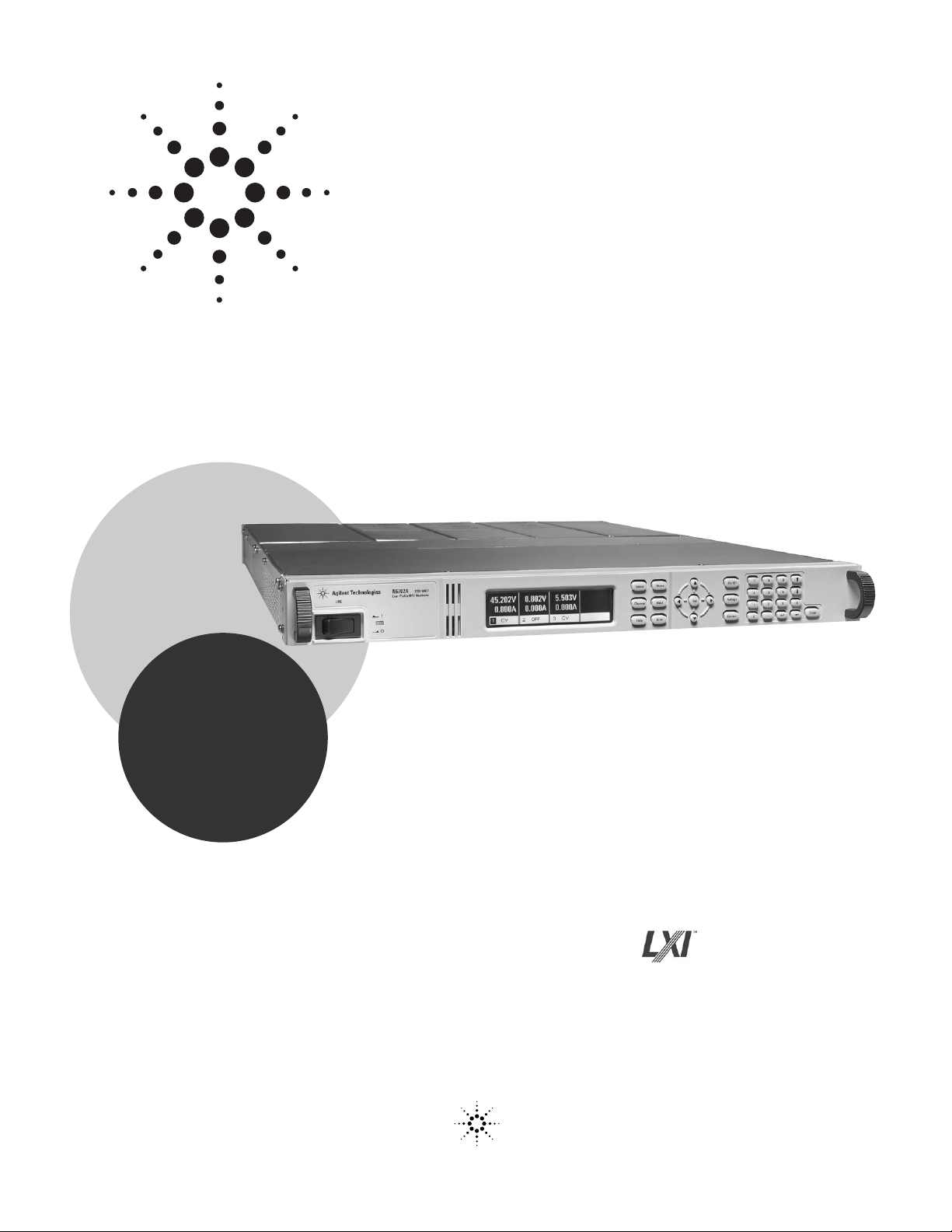
Agilent N6700 MPS
Low-Profile Modular Power System
Models: N6700B, N6701A, N6702A, N6710B,
N6711A, N6712A, N6731B-36B,
N6741B-46B, N6751A-52A,
N6761A-62A, N6773A-76A
Product Overview
• Ideal for ATE systems in R&D, Design Validation, and Manufacturing
• Small size: up to 4 outputs in 1U of rack space
• Flexible, modular system: Can mix and match power levels
and performance levels to optimize investment
• Performance modules for critical test requirements
• Value modules for basic DC power requirements
• Fast command processing times to improve throughput
• Connect via GPIB, LAN, or USB
• Fully compliant to LXI Class C specification
New!
Higher Power
in Same Space
Agilent Technologies
Award
Winning Product
See back cover
Power supplies are a fundamental
component of every test system
in industries including aerospace and defense, consumer
electronics, computers and
peripherals, communications,
semiconductor and automotive
electronics. Today’s complex
automatic test equipment
(ATE) systems often require
multiple power sources. Test
system designers are challenged
to keep costs down by reducing
rack space occupied by these
multiple power supplies and to
continually increase test system
throughput.
The Agilent N6700 Low-Profile
Modular Power System (MPS) is
a 1U (rack unit) high, multipleoutput programmable DC power
supply system that enables test
system integrators to optimize
performance, power and price
to match test needs.
The Agilent N6700 MPS gives
test system designers the flexibility to mix and match from
20 different DC power modules
to create a 1- to 4-channel
DC power system optimized to
meet specific test requirements.
Test system engineers can invest
in high-performance outputs
where speed and accuracy
are needed, or purchase basic
performance outputs for simple
DC power requirements.
Small Size
The Agilent N6700 MPS uses
an advanced switching power
supply design that fits within
1U of rack space. It has side
air vents (no top or bottom air
vents) so other instruments
can be mounted directly above
or below it. (Requires rack
mount kit; see Ordering
Information.)
Built-in Measurement
of Voltage and Current
The N6700 modules come
standard with built-in
measurement of voltage and
current to simplify wiring
and design of an ATE system.
2
N6700 System Features
Small Size and
Flexibility for ATE
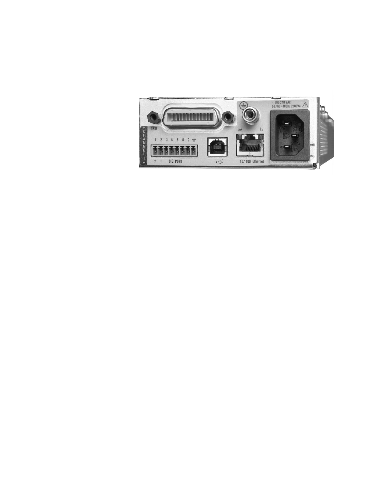
Figure 1. Connectivity: GPIB, 10/100 Base-T Ethernet, and USB 2.0 all standard

Protection Features
Each N6700 module is protected
against over-voltage, overcurrent, and over-temperature.
A fault condition in one
module can be detected within
10 microseconds by other modules so that they can be quickly
shut down to avoid hazardous
conditions on your DUT.
Connectivity
The N6700 MPS comes standard
with GPIB, USB 2.0, and
10/100 Base-T Ethernet LAN
interfaces. While GPIB is best
suited for use with existing
systems, Agilent offers USB
and LAN to allow you to take
advantage of the availability,
speed, and ease-of-use of
common computer industry
standard interfaces. The N6700
is fully compliant with the LXI
Class C specification.
Security
When used in systems running
GPIB, the LAN and/or USB
interfaces can be disabled
for extra security. Also, all
non-volatile RAM data and
settings can be cleared from
the front panel.
Control from any Browser
The N6700 can be controlled
via a standard web browser.
The N6700 contains a web
server that provides web pages
for monitor, control, and setup
of the MPS.
Output Sequencing
Each DC power module can be
individually set to turn on or
to turn off with a delay. By
adjusting the delay times and
then commanding the N6700 to
turn on, you can set the N6700
modules to sequence on in a
particular order. The same
sequencing capability is available to shut down the modules
in a particular order.
3
Module 1
Output on
V1
V2
V3
Module 2
Delay 2
Delay 3
Module 3
Figure 2. Output Sequencing

Programmable Voltage Slew
For some applications, like
inrush limiting or powering
rate-sensitive devices, it is
necessary to slow down and
control the speed of the power
supply to maintain a specific
voltage slew rate. The N6700
provides programmable voltage
slew rate, so that with a single
command, you can generate a
0 V to full-scale voltage change
controllable from 1 millisecond
to 10 seconds. Programmable
voltage slew is available from
the front panel when operating
the N6700 manually or via
computer control.
Series Operation
To increase available voltage
and power, similarly rated
outputs can be operated
directly in series.
Easy Parallel Operation
with Virtual Channels
To increase available output
power and current, identical
outputs can be operated in
parallel. To simplify parallel
operation for applications
requiring currents greater
than any single output can
provide, the N6700 offers
virtual channels, a firmwarebased feature that allows
the N6700 system to treat
up to 4 channels as a single,
synchronized channel. Once
configured, all functions
(sourcing, measurements,
triggering, protection, and
status monitoring) behave
as if there is 1 channel of
up to 4 times the capacity
of a single channel, without
writing a single line of code
to manage the interaction
and synchronization of the
paralleled power supplies.
Virtual channel capability is
available from the front panel
when operating the N6700
manually or via computer
control.
Power Management Feature Allows
You Allocate Mainframe Power
Often, a DUT requires a single
high power DC source and
several very low power DC
sources. Since the DUT does
not require full power to all
outputs, you may choose to
save money configuring a
system where the sum of the
power modules installed in a
mainframe exceeds the total
power available from the mainframe. In this case, the new
power management features of
the N6700 allow you to allocate
mainframe power to the outputs
where it’s needed, achieving
maximum asset utilization and
flexibility. This feature provides
the safety from unexpected
and dangerous shutdowns that
can occur with power systems
without power management
when operated in a similar way.
For example, if your DUT
requires 280 W on its main
input, and 10 W each on three
auxiliary inputs, you can configure a system consisting of
one 300 W DC module and
three 100 W DC modules. Even
though the sum of the module
power is 600 W, you can still
use the N6700B 400 W MPS
mainframe. Thanks to the
power management feature,
you can allocate the full 300 W
to the 300 W module while you
allocate only 33 W to each of
the 100 W modules.
4

Plug High Power Mainframes
into Standard AC Sockets without
Dedicated High Current AC Circuits
When you first turn on the
N6702A 1200 W MPS mainframe,
the mainframe automatically
senses the power available from
the AC line. If the AC line voltage is such that the resulting
current would exceed a standard
AC outlet rating, the mainframe
automatically scales back the
available output power to prevent overloading the AC line.
The N6702A will limit the output
power to 600 W allowing the
high power mainframe to be
plugged into any standard outlet. This is very convenient for
initial bench checkout of the
MPS system. It is also very
convenient for test development,
which is typically done on the
bench when DUT is not yet
driven to full power. You can
also control this power reduction
by manually allocating less than
the full available mainframe
power among the modules. As
a result, the N6702A will draw
less power (and less current)
from the AC line.
Triggering
The N6700 Low-Profile MPS
mainframe has hardware trigger
in/trigger out signals which
permit the N6700 to be synchronized with external events.
For example, a switch closure
in the fixture can trigger the
N6700 to turn on power to
the DUT, or change voltage,
or take a measurement.
Drivers
The N6700 comes with both
VXIplug&play drivers and
IVI-COM drivers. LabView
drivers are available at NI.COM.
Programming Language
The N6700 supports SCPI
(Standard Commands for
Programmable Instruments).
Firmware Updates
The N6700 firmware is stored in
FLASH ROM and can be easily
updated when new features
become available. Firmware can
be downloaded into the N6700
over GPIB, LAN, or USB using
the supplied firmware update
utility program. Firmware
updates can be found at
www.agilent.com/find/N6700firmware.
Output Disconnect and
Polarity Reversal Relays
Modules in the N6700 can
be individually ordered with
optional Output Disconnect
Relays (option 761) or Output
Disconnect/Polarity Reversal
Relays (option 760). See table on
page 25 for option 760 and 761
availability. All relays are built
into the module, so no additional
wiring or rack space is needed
to get the relay function.
With option 761, Output
Disconnect Relays, mechanical
relays disconnect both the plus
and minus side of the power
supply, including the sense leads.
With option 760, Output
Disconnect/Polarity Reversal
Relays, mechanical relays switch
the leads on both the plus and
minus side of the power supply,
including the sense leads,
resulting in a voltage polarity
reversal at the DUT. In addition
to polarity reversal, option 760
provides the same output disconnect function as option 761.
5
Front Panel
In addition to full control over
its three standard interfaces, the
N6700 has a full featured front
panel to permit easy manual
operation for test prototyping,
debugging, and troubleshooting
when used in an ATE system.
You can have confidence that
the N6700 is working properly
because you can view the
settings and actual output
values on all four outputs at
the same time.
Quieter Fans to Keep Noise Down
To reduce acoustic noise, the
N6700 mainframes employ fan
speed control. When operating
at less than full output power,
the cooling fans spin slower
and generate less noise.
Universal AC Input
The N6700 has a universal input
that operates from 100-240 Vac,
50/60/400 Hz. There are no
switches to set or fuses to
change when switching from
one voltage standard to another.
The AC input employs power
factor correction.
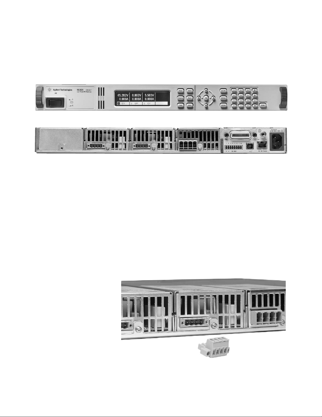
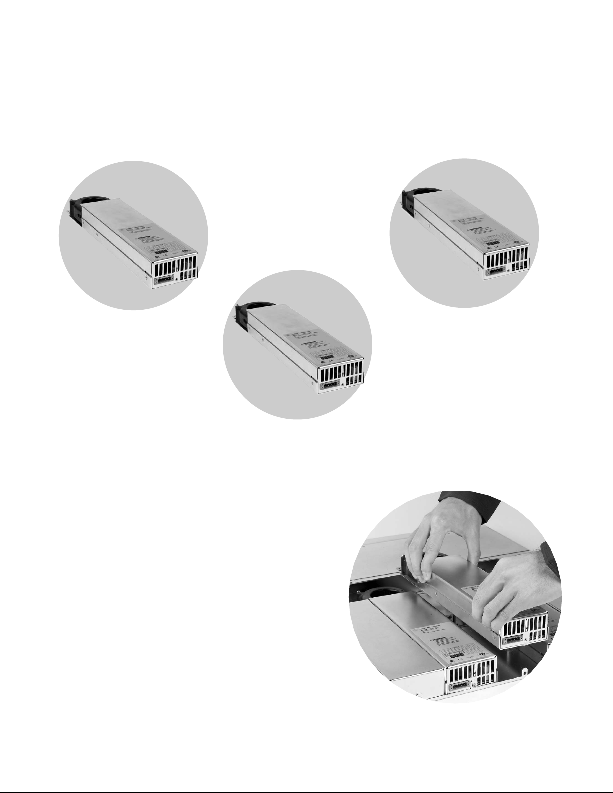
Quick Disconnects
Each power module has quick
disconnects for easy system
setup and maintenance.
Rack Mount Kit
The N6700 is easily rack-mounted
using available option 908.
This kit provides all the necessary hardware to rack mount
one N6700 mainframe in only
1U of rack space. This rack
mount kit includes front rack
ears and rear supports which
take the place of standard rack
rails and/or slides. Note that
standard rack rails or slides
are not needed and are not
compatible with the N6700
because of its 1U size and
airflow requirements.
6
Figure 3. Front panel with up to 4 channels displayed simultaneously (Picture shows 3 channels installed.)
Figure 4. Rear panel (Picture shows 3 channels installed.)
Figure 5. Quick disconnects for power and sense leads
N6750 Family
For applications where
the power supply plays a
critical role
The Agilent N6750 family of
high-performance, autoranging
DC power modules provides
low noise, high accuracy and
programming speeds that are
up to 10 to 50 times faster than
other programmable power
supplies. In addition, Agilent
has, for the first time, included
high-speed test extensions in
general-purpose power supplies.
The high-speed test extensions
offer an oscilloscope-like
digitizer that simplifies system
configuration and increases
measurement accuracy when
viewing high-speed transient or
pulse events within the deviceunder-test (DUT). In addition,
autoranging output capabilities
enable one power supply to do
the job of several traditional
power supplies.
N6760 Family
For applications where
precision is required
The Agilent N6760 family of
precision DC power modules
provides precise control
and measurements in the
milliampere and microampere
region with the ability to
simultaneously digitize
voltage and current,
and capture those
measurements in
an oscilloscope-like
data buffer.
N6730/40/70 Family
For basic DC applications
The Agilent N6730, N6740 and
N6770 families of DC power
modules provide programmable
voltage and current, measurement and protection features
at a very economical price,
making these modules suitable
to power the DUT or to provide
power for ATE system resources,
such as fixture control.
7
Choosing the right DC Power Modules to meet your ATE needs
See detailed specifications on page 13
Figure 6. User re-configurable
modular system
When your testing requires a
power supply to do more than
just provide a constant DC
level, the N6750 family of HighPerformance, Autoranging DC
Power Modules and the N6760
family of Precision DC Power
Modules are the perfect fit.
These modules combine a fast
output with flexible controls
and sophisticated measurements. The N6750/60 is more
than a power supply; it is a
stimulus/response instrument.
To fit in 1U, the N6750/60
use an advanced switch-mode
design that offers the low
output noise and fast output
speed typically found on
linear power supplies.
Low Noise Outputs
Careful attention has been paid
to this design to ensure low
normal mode noise (ripple and
peak-peak) as well as low common mode noise. This switching power supply outperforms
most linear power supplies on
the market.
Output Programming Speed
When it comes to speed, the
N6750/60 achieves performance unlike a typical DC
power supply. Thanks to an
active down-programming
circuit to rapidly pull down
the output when lowering the
module’s output voltage, the
N6750/60 can rapidly program
both up and down in voltage.
Changing voltage from 0 V
to 50 V, or 50 V to 0 V, can
be accomplished in less than
1.5 milliseconds. And for smaller
voltage changes, for example
from 0 V to 5 V or 5 V to 0 V,
the programming speed is
less than 200 microseconds.
These output speeds allow the
N6750/60 to give maximum
system throughput when your
test calls for frequent changes
in power supply voltage settings.
Autoranging for Flexibility
The N6750/60 gives test system
designers even more flexibility
by providing autoranging
outputs. This autoranging
capability provides maximum
output power at any output
voltage up to 50 V. This allows
one power supply to do the
job of several power supplies
because its operating range
covers low voltage, high current as well as high voltage,
low current operating points.
For example, the N6751A
High-Performance, Autoranging
DC Module, rated at 50 V, 5 A,
and 50 W can provide full
power at 10 V @ 5 A (=50 W),
20 V @ 2.5 A (= 50 W), 33.3 V @
1.5 A (= 50 W), 50 V @ 1 A
(= 50 W) or anywhere in
between. Therefore, this 50 W
autoranging power supply,
8
The N6750 and N6760 Families: Performance Modules for when
the power supply is a critical part of your testing
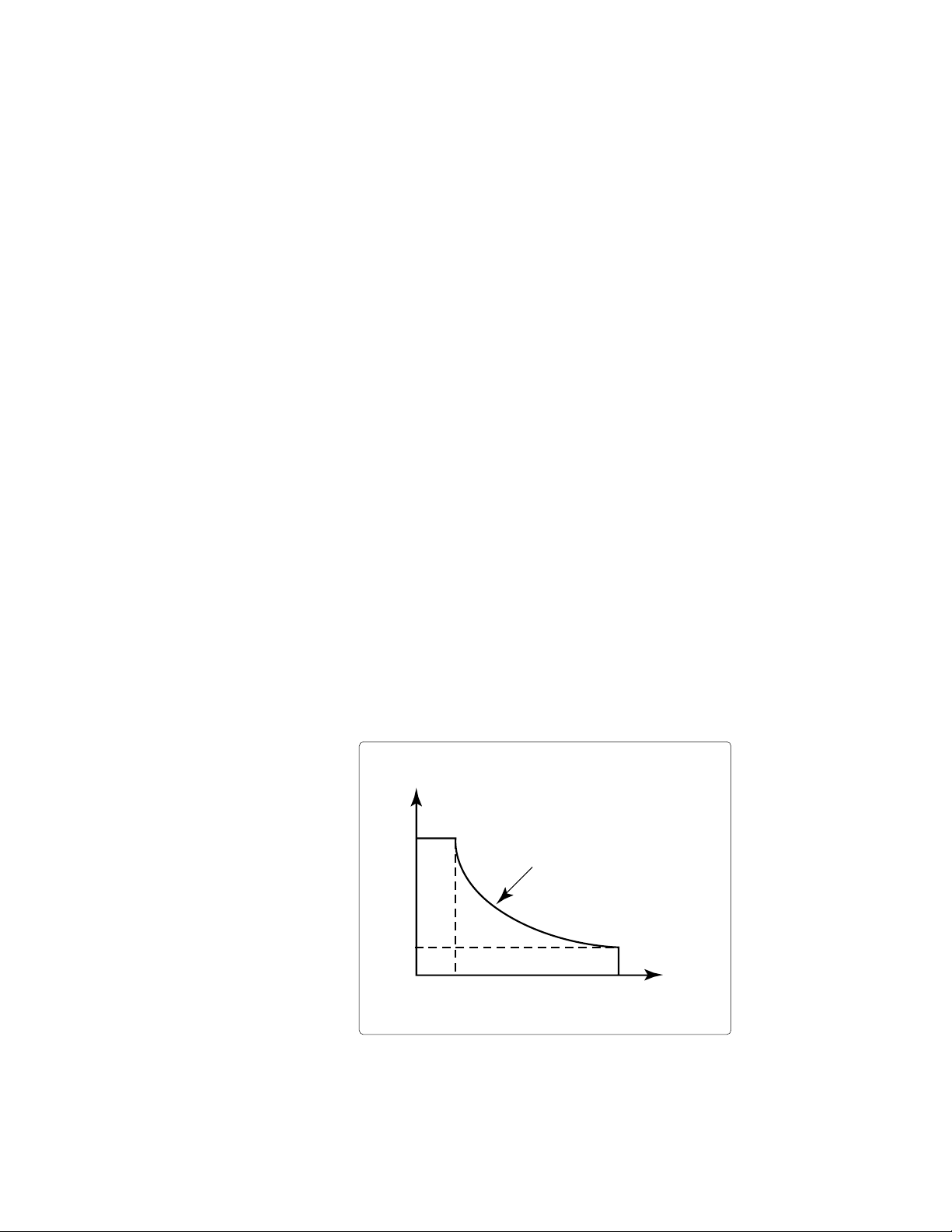
Voltage
Autoranging 50 W Output
Current
50 V
10 V
0 1 A 5 A
50 W Curve
due to its extended voltage
and current range, can produce
voltage and current combinations in the range of a 250 W
non-autoranging power supply.
The flexibility of autoranging is
useful when the DUT operates
over a wide range of voltages,
when the ATE system needs to
test a wide range of DUTs, or
when margin is needed because
the ATE power supply must
be selected before final DUT
power requirements are
determined.
See page 22 for a diagram
describing the details of the
autoranging output characteristics of the N6750 and N6760
families of DC Power Modules.
High-Speed Test Extensions
To make your testing go even
faster, the N6750/60 offer
High-Speed Test Extensions
(HSTE). This enhancement to
the N6750/60 DC Power Modules
extends the capabilities to
include features similar to
a built-in arbitrary waveform
generator and a built-in
oscilloscope. HSTE is optional
on the N6750 DC Power Modules.
HSTE is standard on the N6760
DC Power Modules.
Through the LIST mode of
HSTE, you can download up
to 512 setpoints of voltage and
current. In LIST mode, you can
program the output to execute
a LIST of voltage and current
setpoints. For each setpoint, a
dwell time can be specified and
the power supply will stay (i.e.,
dwell) at that setpoint for the
programmed dwell time value.
For each setpoint in the LIST,
you can have a different dwell
time from 0 to 262 seconds
with 1 microsecond resolution.*
Then, you can trigger the module to begin executing the list.
The module will step thru the
list, staying at each setpoint
for the programmed dwell time,
and then it will move on to the
next point. This speeds up
execution by removing the
computer I/O from the process.
The result is an output that
automatically changes according
to the programmed list, just
like an arbitrary waveform
generator.
* Note that the output response
time is less than 5 milliseconds per voltage change,
so steps of less than 5 milliseconds will not achieve
their final output voltage
value before moving on to
the next step. This is useful
when trying to create a
smooth waveform.
9
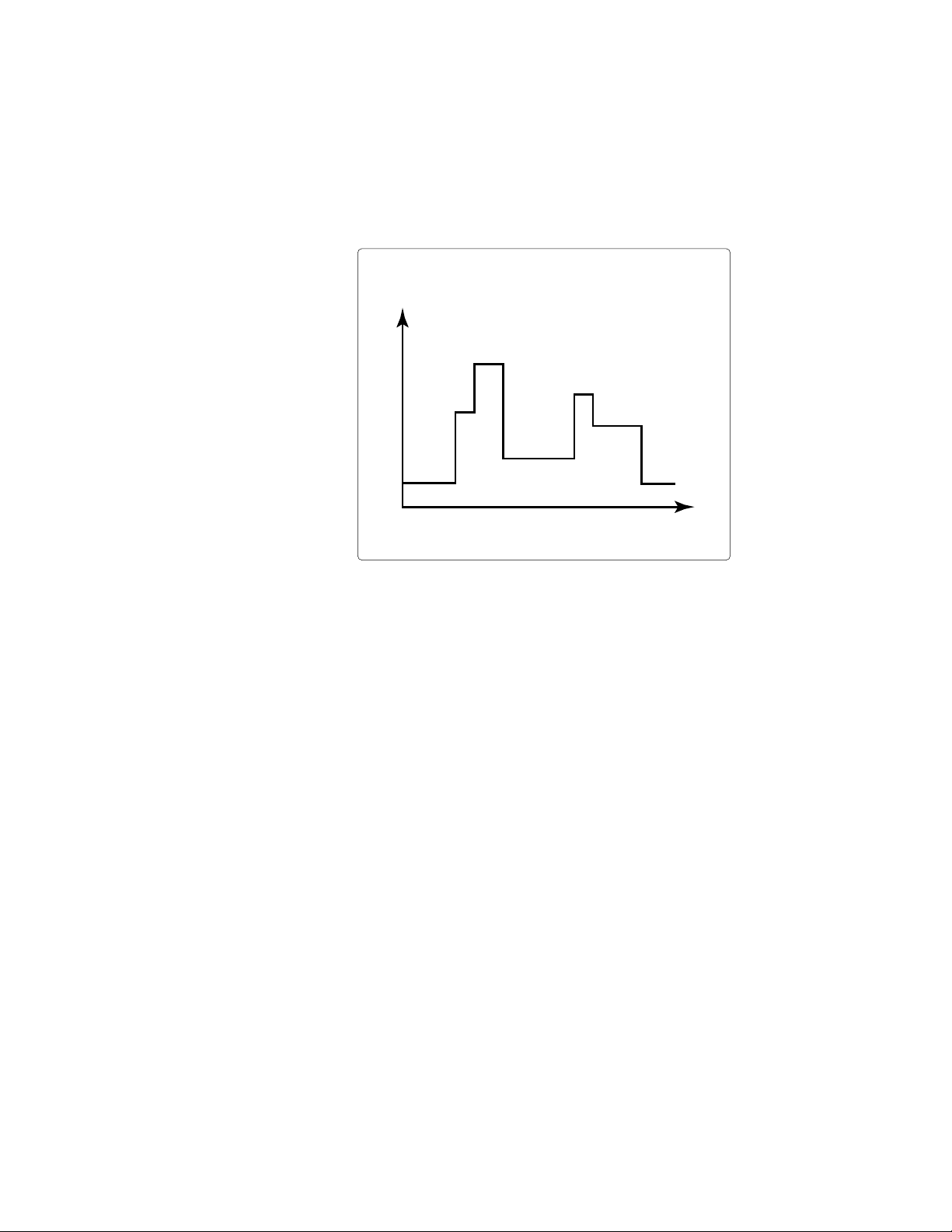
Figure 7. High Speed Test Extensions LIST mode provides “power ARB” capability
Voltage
Time in seconds
 Loading...