


Technical Specifications
Agilent Technologies
PNA Series Network Analyzers
N5242A
Options 200/219/224 (2-Port PNA-X)
Options 400/419/423 (4-Port PNA-X)
Manufacturing Part Number: N5242-90007
Printed in USA
Print Date: September 6, 2007
Supersedes: July 17, 2007
© Copyright © Agilent Technologies, Inc. 2007 All rights reserved.

Documentation Warranty
THE MATERIAL CONTAINED IN THIS DOCUMENT IS PROVIDED "AS IS," AND IS
SUBJECT TO BEING CHANGED, WITHOUT NOTICE, IN FUTURE EDITIONS. FURTHER, TO THE MAXIMUM EXTENT PERMITTED BY APPLICABLE LAW, AGILENT
DISCLAIMS ALL WARRANTIES, EITHER EXPRESS OR IMPLIED WITH REGARD TO
THIS MANUAL AND ANY INFORMATION CONTAINED HEREIN, INCLUDING BUT
NOT LIMITED TO THE IMPLIED WARRANTIES OF MERCHANTABILITY AND FITNESS FOR A PARTICULAR PURPOSE. AGILENT SHALL NOT BE LIABLE FOR
ERRORS OR FOR INCIDENTAL OR CONSEQUENTIAL DAMAGES IN CONNECTION
WITH THE FURNISHING, USE, OR PERFORMANCE OF THIS DOCUMENT OR ANY
INFORMATION CONTAINED HEREIN. SHOULD AGILENT AND THE USER HAVE A
SEPARATE WRITTEN AGREEMENT WITH WARRANTY TERMS COVERING THE
MATERIAL IN THIS DOCUMENT THAT CONFLICT WITH THESE TERMS, THE WARRANTY TERMS IN THE SEPARATE AGREEMENT WILL CONTROL.
DFARS/Restricted Rights Notice
If software is for use in the performance of a U.S. Government prime contract or
subcontract, Software is delivered and licensed as “Commercial computer software” as
defined in DFAR 252.227-7014 (June 1995), or as a “commercial item” as defined in FAR
2.101(a) or as “Restricted computer software” as defined in FAR 52.227-19 (June 1987) or
any equivalent agency regulation or contract clause. Use, duplication or disclosure of
Software is subject to Agilent Technologies’ standard commercial license terms, and
non-DOD Departments and Agencies of the U.S. Government will receive no greater than
Restricted Rights as defined in FAR 52.227-19(c)(1-2) (June 1987). U.S. Government users
will receive no greater than Limited Rights as defined in FAR 52.227-14 (June 1987) or
DFAR 252.227-7015 (b)(2) (November 1995), as applicable in any technical data.
Printing Copies of Documentation from the Web
To print copies of documentation from the Web, download the PDF file from the Agilent
web site:
•Go to www.agilent.com.
• Enter the product model number in the search function and click Search.
• Click on the Manuals hyperlink.
• Open the PDF of your choice and print the document .

Contacting Agilent
Assistance with test and measurement needs and information on finding a local Agilent
office are available on the Web at:
www.agilent.com/find/assist
If you do not have access to the Internet, please contact your Agilent field engineer.
NOTE
In any correspondence or telephone conversation, refer to the Agilent product
by its model number and full serial number. With this information, the
Agilent representative can determine whether your product is still within its
warranty period.

This page intentionally left blank.

Documentation Warranty
THE MATERIAL CONTAINED IN THIS DOCUMENT IS PROVIDED "AS IS," AND IS SUBJECT
TO BEING CHANGED, WITHOUT NOTICE, IN FUTURE EDITIONS. FURTHER, TO THE
MAXIMUM EXTENT PERMITTED BY APPLICABLE LAW, AGILENT DISCLAIMS ALL
WARRANTIES, EITHER EXPRESS OR IMPLIED WITH REGARD TO THIS MANUAL AND ANY
INFORMATION CONTAINED HEREIN, INCLUDING BUT NOT LIMITED TO THE IMPLIED
WARRANTIES OF MERCHANTABILITY AND FITNESS FOR A PARTICULAR PURPOSE.
AGILENT SHALL NOT BE LIABLE FOR ERRORS OR FOR INCIDENTAL OR
CONSEQUENTIAL DAMAGES IN CONNECTION WITH THE FURNISHING, USE, OR
PERFORMANCE OF THIS DOCUMENT OR ANY INFORMATION CONTAINED HEREIN.
SHOULD AGILENT AND THE USER HAVE A SEPARATE WRITTEN AGREEMENT WITH
WARRANTY TERMS COVERING THE MATERIAL IN THIS DOCUMENT THAT CONFLICT
WITH THESE TERMS, THE WARRANTY TERMS IN THE SEPARATE AGREEMENT WILL
CONTROL.
DFARS/Restricted Rights Notice
If software is for use in the performance of a U.S. Government prime contract or subcontract,
Software is delivered and licensed as “Commercial computer software” as defined in DFAR
252.227-7014 (June 1995), or as a “commercial item” as defined in FAR 2.101(a) or as
“Restricted computer software” as defined in FAR 52.227-19 (June 1987) or any equivalent
agency regulation or contract clause. Use, duplication or disclosure of Software is subject to
Agilent Technologies’ standard commercial license terms, and non-DOD Departments and
Agencies of the U.S. Government will receive no greater than Restricted Rights as defined in
FAR 52.227-19(c)(1-2) (June 1987). U.S. Government users will receive no greater than Limited
Rights as defined in FAR 52.227-14 (June 1987) or DFAR 252.227-7015 (b)(2) (November 1995),
as applicable in any technical data.

Definitions ............................................................................................ 4
Corrected System Performance......................................................... 5
Table 1a. System Dynamic Range at Test Port 1.......................................5
Table 1b. System Dynamic Range at Test Port 1.......................................6
Table 1c. System Dynamic Range at Test Port 1........................................7
Table 1d. System Dynamic Range at Test Port 1.......................................8
Table 2a Extended Dynamic Range at Direct Receiver Access Input1......9
Table 2b. Extended Dynamic Range at Direct Receiver Access Input1...10
Table 2c. Extended Dynamic Range at Direct Receiver Access Input1....11
Table 2d. Extended Dynamic Range at Direct Receiver Access Input1...12
N5242A Corrected System Performance with 3.5mm Connectors...........13
Table 3. 85052B Calibration Kit N5242A..................................................13
Table 4. N4433A 4-Port Electronic Calibration Module N5242A..............16
Table 5. N4691B 2- Port Electronic Calibration Module...........................19
Uncorrected System Performance .................................................. 22
Table 6. Error Terms1...............................................................................22
Test Port Output.......................................................................................25
Table 7. Frequency Information ...............................................................25
Table 8a. Maximum Leveled Power.........................................................25
Table 8b. Maximum Leveled Power.........................................................30
Table 8c. Maximum Leveled Power .........................................................31
Table 8d. Maximum Leveled Power.........................................................32
Table 8e. Maximum Leveled Power.........................................................33
Table 8f. Maximum Leveled Power..........................................................34
Table 9a. Power Level Accuracy..............................................................35
Table 9b. Power Level Linearity...............................................................36
Table 9c. (Continued) Power Level Linearity............................................36
Table 9d. Power Level Linearity...............................................................37
Table 10a. Power Sweep Range..............................................................37
Table 10b. Power Sweep Range..............................................................38
Table 10c. Power Sweep Range..............................................................38
Table 10d. Power Sweep Range..............................................................39
Table 11. Nominal Power (Preset Power)................................................39
Table 12. Power Resolution and Maximum/Minimum Settable Power.....40
Table 13. Harmonics at Max Specified Power..........................................41
Table 14. Non-Harmonic Spurs at nominal power....................................42
Table 15. Phase Noise.............................................................................43
Test Port Input ................................................................................... 44
Table 16. Test Port Input ................................................................... 44
2

Dynamic Accuracy ............................................................................ 50
Table 17 Dynamic Accuracy (Specification)............................................. 50
Table 18. Test Port Input (Group Delay)a.................................................57
General Information .......................................................................... 58
Table 19. Miscellaneous Information........................................................58
Table 20. Front Panel Information............................................................58
Table 21 Rear Panel Information .............................................................60
Table 22. Analyzer Dimensions and Weight.............................................65
Measurement Throughput Summary............................................... 66
Table 23. Typical Cycle Timea (ms) for Measurement Completion ..........66
Table 24. Cycle Time vs IF Bandwidth.....................................................68
Table 25. Cycle Time vs Number of Points..............................................69
Table 26. Data Transfer Time (ms) ..........................................................71
Specifications: Front-Panel Jumpers .............................................. 72
Table 27 Measurement Receiver Inputs ..................................................73
Table 28. Reference Receiver Input.........................................................74
Table 29. Reference Receiver Input.........................................................75
Table 30. Reference Output.....................................................................77
Table 31. Reference Output.....................................................................78
Table 32. Source Outputs........................................................................80
Table 33. Coupler Inputs..........................................................................82
Test Set Block Diagrams .................................................................. 83
3

This is a complete list of the technical specifications for the N5242A PNA-X network analyzer with
the following options:
Option 200, 2-port standard test set (includes six front-panel access loops) and power range.
See the block diagram
Option 219, adds 2-port extended power range, source and receiver attenuators, and bias-tees
(requires Option 200). See the block diagram
Option 224, adds an internal second source, a combiner, and mechanical switches to the 2-port
analyzer (requires Option 200, 219, and 080). See the block diagram
Option 400, 4-port standard test set (includes twelve front-panel access loops), power range, and
an internal second source (Option 080 recommended). See the block diagram
Option 419, adds 4-port extended power range, source and receiver attenuators, and bias-tees
(requires Option 400). See the block diagram
Option 423, adds an internal combiner, and mechanical switches to the 4-port analyzer (requires
Option 400, 419, and 080). See the block diagram
Note
This document provides technical specifications for the 85052B calibration kit, the N4433A 4-Port
ECal module, and the N4691B 2-Port ECal module. Please download our free Uncertainty
Calculator from http://www.agilent.com/find/na_calculator to generate the curves for your
calibration kit and PNA setup.
.
.
.
.
.
.
Definitions
All specifications and characteristics apply over a 25 °C ±5 °C range (unless otherwise stated)
and 90 minutes after the instrument has been turned on.
Specification (spec.): Warranted performance. Specifications include guardbands to account for
the expected statistical performance distribution, measurement uncertainties, and changes in
performance due to environmental conditions.
Characteristic (char.): A performance parameter that the product is expected to meet before it
leaves the factory, but that is not verified in the field and is not covered by the product warranty. A
characteristic includes the same guardbands as a specification.
Typical (typ.): Expected performance of an average unit which does not include guardbands. It is
not covered by the product warranty.
Nominal (nom.): A general, descriptive term that does not imply a level of performance. It is not
covered by the product warranty.
Calibration: The process of measuring known standards to characterize a network analyzer's
systematic (repeatable) errors.
Corrected (residual): Indicates performance after error correction (calibration). It is determined
by the quality of calibration s tandards and ho w well "known" they are, plus system repeatabili t y,
stability, and noise.
Uncorrected (raw): Indicates instrument performance without error correction. The uncorrected
performance affects the stability of a calibration.
Standard: When referring to the analyzer, this includes no options unless noted otherwise.
4

Corrected System Performance
The specifications in this section apply for measurements made with the N5242A analyzer with
the following conditions:
• 10 Hz IF bandwidth
• No averaging applied to data
• Isolation calibration with an averaging factor of 8
Table 1a. System Dynamic Range at Test Port
1
Option 200 or 400
Description Specification (dB) at Test Port Typical (dB) at Test Port
Port 1 or 32 Port 2 or 42 Port 1 or 32 Port 2 or 42
10 MHz to 50 MHz3 93 93 106 104
50 MHz to 100 MHz3 103 103 116 115
100 MHz to 500 MHz3 117 117 131 130
500 MHz to 3.2 GHz 124 127 130 135
3.2 GHz to 10 GHz 127 127 137 136
10 GHz to 16 GHz 127 127 134 133
16 GHz to 20 GHz 127 124 133 129
20 GHz to 24 GHz 122 117 130 126
24 GHz to 26.5 GHz 112 109 124 120
1. The system dynamic range is calculated as the difference between the noise floor and the
specified source maximum output power. The effective dynamic range must take
measurement uncertainties and interfering signals into account.
2. Either port can be used as the source port. Any other port can be used as the receiver port.
3. May typically be degraded at particular frequencies below 500 MHz due to spurious receiver
residuals.
5

Table 1b. System Dynamic Range at Test Port
1
Option 219 or 419
Description Specification (dB) at Test Port Typical (dB) at Test Port
Port 1 or
2
3
Port 2 or 4
2
Port 1 or 32 Port 2 or 42
10 MHz to 50 MHz3 93 93 106 104
50 MHz to 100 MHz3 103 103 115 114
100 MHz to 500 MHz3 117 117 130 129
500 MHz to 3.2 GHz 124 127 130 135
3.2 GHz to 10 GHz 127 127 135 134
10 GHz to 16 GHz 126 125 132 131
16 GHz to 20 GHz 124 122 130 127
20 GHz to 24 GHz 118 117 127 124
24 GHz to 26.5 GHz 110 106 121 117
1
The system dynamic range is calculated as the difference between the noise floor and the
specified source maximum output power. The effective dynamic range must take measurement
uncertainties and interfering signals into account.
2
Either port can be used as the source port. Any other port can be used as the receiver port.
3
May typically be degraded at particular frequencies below 500 MHz due to spurious receiver
residuals.
6

Table 1c. System Dynamic Range at Test Port
1
Option 224
Description Specification (dB) at Test Port Typical (dB) at Test Port
Source 2,
Out 1
Source 2,
Out 2
Source 2,
Out 1
Source 2,
Out 2
10 MHz to 50 MHz2 98 93 108 105
50 MHz to 100 MHz2 108 107 117 116
100 MHz to 500 MHz2 122 121 132 131
500 MHz to 3.2 GHz 128 128 134 136
3.2 GHz to 10 GHz 132 132 139 139
10 GHz to 16 GHz 130 130 138 137
16 GHz to 20 GHz 129 127 136 134
20 GHz to 24 GHz 123 122 133 132
24 GHz to 26.5 GHz 114 112 127 124
1
The system dynamic range is calculated as the difference between the noise floor and the
specified source maximum output power. The effective dynamic range must take measurement
uncertainties and interfering signals into account.
2
May typically be degraded at particular frequencies below 500 MHz due to spurious receiver
residuals.
7

Table 1d. System Dynamic Range at Test Port
Option 224 or 423
1
Description Specification
Typical (dB) at Test Port
(dB) at Test Port
Port 1
or 3
Port 2
2
or 42
Port 1
or 32
Port 2
or 42
Source 1, Port
1 Combine
Mode
Source 2, Port
1 Combine
Mode
10 MHz to 50 MHz3 93 93 106 104 104 80
50 MHz to 100
3
MHz
100 MHz to 500
3
MHz
103 103 115 115 112 90
117 117 130 130 121 99
500 MHz to 3.2 GHz 124 127 130 134 127 112
3.2 GHz to 10 GHz 127 127 136 134 132 119
10 GHz to 16 GHz 126 124 132 131 128 115
16 GHz to 20 GHz 124 121 130 127 125 113
20 GHz to 24 GHz 117 115 127 124 121 109
24 GHz to 26.5 GHz 107 105 121 117 115 102
1
The system dynamic range is calculated as the difference between the noise floor and the
specified source maximum output power. The effective dynamic range must take measurement
uncertainties and interfering signals into account.
2
Either port can be used as the source port. Any other port can be used as the receiver port.
3
May typically be degraded at particular frequencies below 500 MHz due to spurious receiver
residuals.
8

1
Table 2a Extended Dynamic Range at Direct Receiver Access Input
Option 200 or 400
Description Typical (dB) at Direct Receiver Access Input
Port 1 or 32 Port 2 or 42
10 MHz to 50 MHz3 128 128
50 MHz to 100 MHz3 115 115
100 MHz to 500MHz3 129 129
500 MHz to 3.2 GHz 136 139
3.2 GHz to 10 GHz 139 139
10 GHz to 16 GHz 139 139
16 GHz to 20 GHz 139 136
20 GHz to 24 GHz 134 129
24 GHz to 26.5 GHz 124 121
1
The direct receiver access input extended dynamic range is calculated as the difference
between the direct receiver access input noise floor and the source maximum output power. The
effective dynamic range must take measurement uncertainties and interfering signals into
account. This set-up should only be used when the receiver input will never exceed its maximum
receiver input. When the analyzer is in segment sweep mode, it can have predefined frequency
segments which will output a higher power level when the extended dynamic range is required
(i.e. devices with high insertion loss), and reduced power when the maximum receiver input level
will occur (i.e. devices with low insertion loss). The extended range is only available in one-path
transmission measurements.
2
Either port can be used as the source port. Any other port can be used as the receiver port.
3
May typically be degraded at particular frequencies below 500 MHz due to spurious receiver
residuals.
9

Table 2b. Extended Dynamic Range at Direct Receiver Access Input1
Option 219 or 419
Description Typical (dB) at Direct Receiver Access Input
Port 1 or 32 Port 2 or 42
10 MHz to 50 MHz3 128 128
50 MHz to 100 MHz3 115 115
100 MHz to 500MHz3 129 129
500 MHz to 3.2 GHz 136 139
3.2 GHz to 10 GHz 139 139
10 GHz to 16 GHz 138 137
16 GHz to 20 GHz 136 134
20 GHz to 24 GHz 130 129
24 GHz to 26.5 GHz 122 118
1
The direct receiver access input extended dynamic range is calculated as the difference
between the direct receiver access input noise floor and the source maximum output power. The
effective dynamic range must take measurement uncertainties and interfering signals into
account. This set-up should only be used when the receiver input will never exceed its maximum
receiver input. When the analyzer is in segment sweep mode, it can have predefined frequency
segments which will output a higher power level when the extended dynamic range is required
(i.e. devices with high insertion loss), and reduced power when the maximum receiver input level
will occur (i.e. devices with low insertion loss). The extended range is only available in one-path
transmission measurements.
2
Either port can be used as the source port. Any other port can be used as the receiver port.
3
May typically be degraded at particular frequencies below 500 MHz due to spurious receiver
residuals.
10

Table 2c. Extended Dynamic Range at Direct Receiver Access Input1
Option 224
Description Typical (dB) at Direct Receiver Access Input
Source 2, Out 1 Source 2, Out 2
10 MHz to 50 MHz2 133 128
50 MHz to 100 MHz2 120 119
100 MHz to 500MHz2 134 133
500 MHz to 3.2 GHz 140 140
3.2 GHz to 10 GHz 144 144
10 GHz to 16 GHz 142 142
16 GHz to 20 GHz 141 139
20 GHz to 24 GHz 135 134
24 GHz to 26.5 GHz 126 124
1
The direct receiver access input extended dynamic range is calculated as the difference
between the direct receiver access input noise floor and the source maximum output power. The
effective dynamic range must take measurement uncertainties and interfering signals into
account. This set-up should only be used when the receiver input will never exceed its
compression or damage level. When the analyzer is in segment sweep mode, it can have
predefined frequency segments which will output a higher power level when the extended
dynamic range is required (i.e. devices with high insertion loss), and reduced power when
receiver compression or damage may occur (i.e. devices with low insertion loss). The extended
range is only available in one-path transmission measurements.
2
May typically be degraded at particular frequencies below 500 MHz due to spurious receiver
residuals.
11

Table 2d. Extended Dynamic Range at Direct Receiver Access Input1
Option 224 or 423
Description Typical (dB) at Direct Receiver Access Input
Port 1
or 3
Port 2
2
or 42
Source 1, Port 1
Combine Mode
Source 2, Port 1
Combine Mode
10 MHz to 50 MHz3 128 128 139 115
50 MHz to 100 MHz3 115 115 124 102
100 MHz to 500MHz3 129 129 133 111
500 MHz to 3.2 GHz 136 139 139 124
3.2 GHz to 10 GHz 139 139 144 131
10 GHz to 16 GHz 138 136 140 127
16 GHz to 20 GHz 136 133 137 125
20 GHz to 24 GHz 129 127 133 121
24 GHz to 26.5 GHz 119 121 127 114
1
The direct receiver access input extended dynamic range is calculated as the difference
between the direct receiver access input noise floor and the source maximum output power. The
effective dynamic range must take measurement uncertainties and interfering signals into
account. This set-up should only be used when the receiver input will never exceed its
compression or damage level. When the analyzer is in segment sweep mode, it can have
predefined frequency segments which will output a higher power level when the extended
dynamic range is required (i.e. devices with high insertion loss), and reduced power when
receiver compression or damage may occur (i.e. devices with low insertion loss). The extended
range is only available in one-path transmission measurements.
2
Either port can be used as the source port. Any other port can be used as the receiver port.
3
May typically be degraded at particular frequencies below 500 MHz due to spurious receiver
residuals.
Receiver Dynamic Range technical specifications are not provided in this N5242A specs
document.
12

N5242A Corrected System Performance with 3.5mm Connectors
All Options
Note: For any Sii reflection measurement:
• Sjj = 0.
For any Sij transmission measurement:
• Sji = Sij when Sij ≤ 1
• Sji = 1/Sij when Sij ≥ 1
• Skk = 0 for all k
Table 3. 85052B Calibration Kit N5242A
All Options
Applies to the N5242A Option 200 or 219 or 224 or 400 or 419 or 423 analyzers, 85052B
(3.5mm) calibration kit, 85131F flexible test port cable set, and a full 2-port calibration. Also
applies to the following condition:
Environmental temperature 23° ±3 °C, with < 1 °C deviation from calibration temperature
Description Specification (dB)
50 MHz to
500 MHz
500 MHz to
2 GHz
2 to
20 GHz
20 to
26.5 GHz
Directivity 48 48 44 44
Source Match 40 40 31 31
Load Match 48 48 44 44
Reflection Tracking 1 ±0.003
+0.010/°C
Transmission Tracking 1 ±0.017
+0.010/°C
1
Temperature deviation is a characteristic value.
±0.003
+0.010/°C
±0.017
+0.010/°C
±0.006
+0.020/°C
±0.104
+0.020/°C
±0.006
+0.030/°C
±0.119
+0.030/°C
13
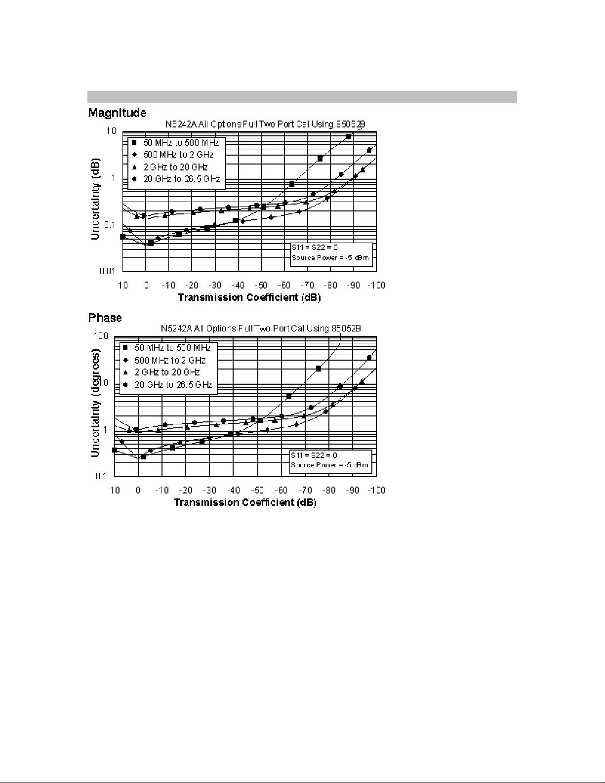
Transmission Uncertainty (Specifications)
14

Reflection Uncertainty (Specifications)
15

Table 4. N4433A 4-Port Electronic Calibration Module N5242A
All Options
Note: Uncertainty curves for the N4433A are created using a 2-port calibration. Multiport
uncertainties are not supported at this time.
Applies to the N5242A Option 200 or 219 or 224 or 400 or 419 or 423 analyzers, N4433A
(3.5mm) electronic calibration module, 85131F flexible test port cable set, and a full 2-port
calibration. Also applies to the following condition:
Environmental temperature 23° ±3 °C, with < 1 °C deviation from calibration temperature
Description Specification (dB)
50 MHz to
500 MHz
500 MHz to
2 GHz
2 to
20 GHz
Directivity 52 52 45
Source Match 42 42 31
Load Match 41 41 29
Reflection Tracking 1 ±0.060
+0.010/°C
Transmission Tracking 1 ±0.063
+0.010/°C
1
Temperature deviation is a characteristic value.
±0.060
+0.010/°C
±0.063
+0.010/°C
±0.180
+0.020/°C
±0.197
+0.020/°C
16
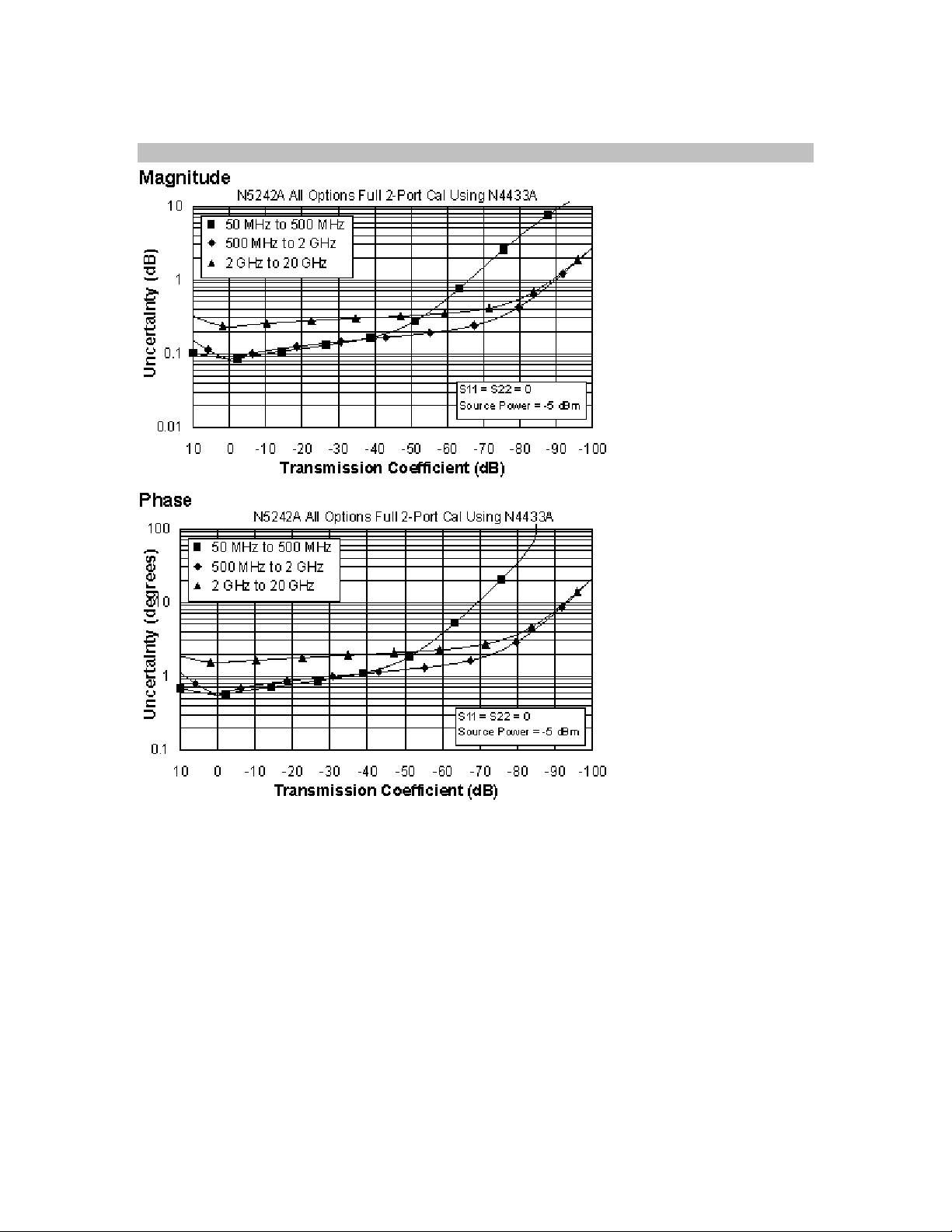
Transmission Uncertainty (Specifications)
17

Reflection Uncertainty (Specifications)
18

Table 5. N4691B 2- Port Electronic Calibration Module
N5242A All Options
Applies to the N5242A Option 200 or 219 or 224 or 400 or 419 or 423 analyzers, N4691B
(3.5mm) electronic calibration module, 85131F flexible test port cable set, and a full 2-port
calibration. Also applies to the following condition:
Environmental temperature 23° ±3 °C, with < 1 °C deviation from calibration temperature
Description Specification (dB)
50 MHz to
500 MHz
500 MHz to
2 GHz
2 to
20 GHz
20 to
26.5 GHz
Directivity 46 56 48 44
Source Match 41 47 44 40
Load Match 40 46 42 38
Reflection Tracking 1 ±0.050
+0.010/°C
Transmission Tracking 1 ±0.056
+0.010/°C
1
Temperature deviation is a characteristic value.
±0.020
+0.010/°C
±0.022
+0.010/°C
±0.040
+0.020/°C
±0.052
+0.020/°C
±0.050
+0.030/°C
±0.072
+0.030/°C
19

Transmission Uncertainty (Specifications)
20

Reflection Uncertainty (Specifications)
This N5242A document does not present specifications for the 85052C or 85052D Calibration Kit.
Please download our free Uncertainty Calculator from http://www.agilent.com/find/na_calculator
to generate the data and curves for the 85052C or the 85052D Calibration Kit.
21

Uncorrected System Performance
Table 6. Error Terms
1
All Options - Ports 1, 2, 3, 4
Description Specification Typical
Directivity (dB)
10 MHz to 50 MHz 16 23
50 MHz to 500 MHz 24 28
500 MHz to 3.2 GHz 24 32
3.2 GHz to 10 GHz 23 25
10 GHz to 16 GHz 16 22
16 GHz to 20 GHz 16 22
20 GHz to 24 GHz 16 22
24 GHz to 26.5 GHz 16 22
Source Match (dB)
10 MHz to 50 MHz 11 14
50 MHz to 500 MHz 18 28
500 MHz to 3.2 GHz 18 22
3.2 GHz to 10 GHz 14 18
10 GHz to 16 GHz 12 16
16 GHz to 20 GHz 10 15
20 GHz to 24 GHz 10 14
24 GHz to 26.5 GHz 8 12
Load Match (dB)
10 MHz to 50 MHz 11 18
50 MHz to 500 MHz 17 25
500 MHz to 3.2 GHz 17 22
3.2 GHz to 10 GHz 13 17
10 GHz to 16 GHz 10 15
16 GHz to 20 GHz 9 14
20 GHz to 24 GHz 9 14
22

Description Specification Typical
24 GHz to 26.5 GHz 8 13
Transmission Tracking3 (dB)
10 MHz to 50 MHz
50 MHz to 500 MHz
500 MHz to 3.2 GHz
3.2 GHz to 10 GHz
10 GHz to 16 GHz
16 GHz to 20 GHz
20 GHz to 24 GHz
24 GHz to 26.5 GHz
Reflection Tracking (dB)
10 MHz to 50 MHz
50 MHz to 500 MHz
500 MHz to 3.2 GHz
3.2 GHz to 10 GHz
10 GHz to 16 GHz
-- +/-1.5
-- +/-1.5
16 GHz to 20 GHz
20 GHz to 24 GHz
24 GHz to 26.5 GHz
23

Crosstalk
10 MHz to 50 MHz -84
4
(dB)
-50 MHz to 100 MHz -90
100 MHz to 500 MHz -110
500 MHz to 3.2 GHz -120
3.2 GHz to 20 GHz -122
20 GHz to 24 GHz -117
24 GHz to 26.5 GHz
1
Specifications apply over environmental temperature of 25 °C ±5 °C, with less than 1°C variation
-114
from the calibration temperature.
3
Cable loss not included.
4
Measurement conditions: normalized to a thru, measured with two shorts, 10 Hz IF bandwidth,
averaging factor of 8, alternate mode, source power set to the lesser of the maximum power-out
or the maximum receiver power.
24
 Loading...