


Agilent 6000 Series
Oscilloscopes
User’s Guide
Agilent Technologies

Notices
© Agilent Technologies, Inc. 2005-2007
No p art o f this manu al may be re produce d in
any form or by any means (including electronic storage and retrieval or translation
into a foreign language) without prior agreement and written consent from Agilent
Technologies, Inc. as governed by United
States and international copyright laws.
Manual Part Number
54684-97020
Edition
Seventh Edition, April 2007
Printed in Malaysia
Agilent Technologies, Inc.
395 Page Mill Road
Palo Alto, CA 94303 USA
A newer version of this manual
may be available at
www.agilent.com/find/mso6000
Software Revision
This guide was written for version 04.10 of
the Agilent 6000 Series Oscilloscope software.
Trademark Acknowledgments
Java is a U.S. trademark of Sun Microsystems, Inc.
Sun, Sun Microsystems, and the Sun Logo
are trademarks or registered trademarks of
Sun Microsystems, Inc. in the U.S. and other
countries.
Windows and MS Windows are U.S. registered trademarks of Microsoft Corporation.
Warranty
The material contained in this document is provided “as is,” and is subject to being changed, without notice,
in future editions. Further, to the maximum extent permitted by applicable
law, Agilent disclaims all warranties,
either express or implied, with regard
to this manual and any information
contained herein, including but not
limited to the implied warranties of
merchantability and fitness for a particular purpose. Agilent shall not be
liable for errors or for incidental or
consequential damages in connection with the furnishing, use, or performance of this document or of any
information contained herein. Should
Agilent and the user have a separate
written agreement with warranty
terms covering the material in this
document that conflict with these
terms, the warranty terms in the separate agreement shall control.
Technology Licenses
The hardware and/or software described in
this document are furnished under a license
and may be used or copied only in accordance with the terms of such license.
Restricted Rights Legend
If software is for use in the performance of a
U.S. Government prime contract or subcontract, Software is delivered and licensed as
“Commercial computer software” as
defined in DFAR 252.227-7014 (June 1995),
or as a “commercial item” as defined in FAR
2.101(a) or as “Restricted computer software” as defined in FAR 52.227-19 (June
1987) or any equivalent agency regulation or
contract clause. Use, duplication or disclosure of Software is subject to Agilent Technologies’ standard commercial license
terms, and non-DOD Departments and
Agencies of the U.S. Government will
receive no greater than Restricted Rights as
defined in FAR 52.227-19(c)(1-2) (June
1987). U.S. Government users will receive
no greater than Limited Rights as defined in
FAR 52.227-14 (June 1987) or DFAR
252.227-7015 (b)(2) (November 1995), as
applicable in any technical data.
Safety Notices
CAUTION
A CAUTION notice denotes a hazard. It calls attention to an operating procedure, practice, or the like
that, if not correctly performed or
adhered to, could result in damage
to the product or loss of important
data. Do not proceed beyond a
CAUTION notice until the indicated
conditions are fully understood and
met.
WARNING
A WARNING notice denotes a
hazard. It calls attention to an
operating procedure, practice, or
the like that, if not correctly performed or adhered to, could result
in personal injury or death. Do not
proceed beyond a WARNING
notice until the indicated conditions are fully understood and
met.
6000 Series Oscilloscope User’s Guide

In This User’s Guide…
1Getting Started
2 Front-Panel Controls
3 Viewing and Measuring Digital Signals
4 Triggering the Oscilloscope
This guide shows you how to use the 6000 Series oscilloscopes.
It contains the following chapters and topics:
Unpacking and setting up your oscilloscope, using Quick Help.
A quick overview of the front-panel controls.
How to connect and use the digital channels of a mixed-signal
oscilloscope (MSO).
Trigger modes, coupling, noise rejection, holdoff, external
trigger and more. Edge, pulse width, and pattern triggering.
CAN, duration, I
TV/video, and USB triggering modes.
2
C, Nth Edge Burst, LIN, sequence, SPI,
5 Making Measurements
XY mode, FFTs, math functions, using cursors, automatic
measurements.
6 Displaying Data
Using pan and zoom; normal, average, peak detect, and high
resolution (smoothing) modes; noise rejection modes, glitch
capture, and more.
7 Saving and Printing Data
Printing waveforms, saving setups and data, and using the file
explorer.
8 Reference
Upgrading a DSO to an MSO, adding memory, software updates,
I/O, synchronizing instruments with the 10 MHz reference
clock, warranty status, digital signal probing, and more.
9 Characteristics and Specifications
Specifications and characteristics of the oscilloscope.
6000 Series Oscilloscope User’s Guide 3

The Agilent 6000 Series oscilloscopes deliver powerful features
and high performance:
• 100 MHz, 300 MHz, 500 MHz, and 1 GHz bandwidth models.
• Up to 4 GSa/s sample rate.
• Powerful triggering including analog HDTV, I
2
C, SPI, LIN,
CAN, and USB.
• USB, LAN, and GPIB ports make printing, saving and
sharing data easy.
• 2-channel and 4-channel Digital Storage Oscilloscope (DSO)
models.
• 2+16-channel and 4+16-channel Mixed Signal Oscilloscope
(MSO) models.
• Color XGA display on 6000A Series models.
• 6000L models are LXI class C compliant, in a 1 unit high
package.
• An MSO lets you debug your mixed-signal designs using up
to four analog signals and 16 tightly correlated digital
signals simultaneously.
• You can easily upgrade a 6000A or 6000L Series oscilloscope
from a DSO to an MSO.
• You can easily increase memory depth of a 6000A Series
oscilloscope. Maximum memory depth is standard in 6000L
Series oscilloscopes.
•You can easily add SPI and I
2
C decode or CAN and LIN
automotive trigger and decode.
The 6000 Series oscilloscopes feature MegaZoom III technology:
• Most responsive deep memory.
• Highest definition color display (6000A models).
• Fastest waveform update rates, uncompromised.
For more information about 6000 Series oscilloscopes, see
www.agilent.com/find/mso6000.
4 6000 Series Oscilloscope User’s Guide

Tabl e 1 Model Numbers, Bandwidths, and Sampling Rates
Bandwidth 100 MHz 300 MHz 500 MHz 1 GHz
Maximum Sample Rate 2 GSa/s 2 GSa/s 4 GSa/s 4 GSa/s
2-Channel + 16 Logic
Channels MSO
4-Channel + 16 Logic
Channels MSO
2-Channel DSO DSO6012A DSO6032A DSO6052A DSO6102A
4-Channel DSO DSO6014A,
MSO6012A MSO6032A MSO6052A MSO6102A
MSO6014A MSO6034A MSO6054A MSO6104A
DSO6014L
DSO6034A DSO6054A,
DSO6054L
DSO6104A,
DSO6104L
Tabl e 2 Secure Environment Mode Option
Oscilloscope History Action
New order. No history. Order Option SEC. The Secure option
will be installed at the factory.
Previously purchased, no confidential
trace or user data has been stored.
Previously purchased, confidential
trace or user data has been stored.
Order N5427A. Return unit to Service
Center for Secure option installation.
Order N5427A. Replace acquisition
board. Destroy old acquisition board.
Return unit to Service Center for
Secure option installation.
6000 Series Oscilloscope User’s Guide 5

Memory upgrades can be easily installed without returning the
oscilloscope to a Service Center. These upgrades are licensed.
Tabl e 3 Memory Depth Option Numbers
Maximum Memory Depth 1 Mpts 2 Mpts 8 Mpts
MSO/DSO6012A, MSO/DSO6014A,
MSO/DSO6032A, MSO/DSO6034A
oscilloscopes
MSO/DSO6052A, MSO/DSO6054A,
MSO/DSO6102A, MSO/DSO6104A
oscilloscopes
DSO6014L, DSO6054L, DSO6104L
oscilloscopes
standard 2ML 8ML
standard 2MH 8MH
n/a n/a standard
The following options can be easily installed without returning
the oscilloscope to a Service Center. These upgrades are
licensed.
Tabl e 4 Upgrade Options
Licensed Option Order
Mixed Signal Oscilloscope
(MSO)
I2C/SPI serial decode
option (for 4 channel or
4+16 channel models only)
Order N2914A or N2915A (see data sheet). You
can easily install this option yourself. The logic
cable kit is supplied with the MSO license.
Order N5423A after purchase (Option LSS at time
of purchase). You can easily install this option
yourself.
CAN/LIN automotive
triggering and decode (for 4
channel or 4+16 channel
models only)
N5406A FPGA dynamic
probe for Xilinx
N5434A FPGA dynamic
probe for Altera
Order N5424A after purchase (Option AMS at
time of purchase). You can easily install this
option yourself.
N5406A with Option 001 (Oscilloscope-locked
license) or Option 002 (PC-locked license).
N5434A with Option 001 (Oscilloscope-locked
license) or Option 002 (PC-locked license).
6 6000 Series Oscilloscope User’s Guide

The following option cannot be installed after time of purchase.
Tabl e 5 Order-Only Options
Licensed Option Order
Battery Operation (Option BAT) Available at time of purchase. Option
can not be added after purchase.
Visit www.agilent.com/find/mso6000 to view the 6000A Series and 6000L Series
data sheets.
6000 Series Oscilloscope User’s Guide 7

Built-in Quick Help
A Quick Help system is built into the oscilloscope. Instructions for using the
quick help system are given on page 56.
Digital Channels
Because all of the oscilloscopes in the Agilent 6000 Series have analog channels,
the analog channel topics in this book apply to all instruments. Whenever a topic
discusses the digital channels, that information applies only to Mixed-Signal
Oscilloscope (MSO) models or DSO models that have been upgraded to an MSO.
Using this book with the 6000L Series oscilloscopes
The 6000L Series oscilloscopes do not have a built-in display or front panel
control keys. If you are using a 6000L Series oscilloscope, and this book refers to
using front panel controls, you can use the built-in Web control feature described
on page 42 to complete the instructions.
Abbreviated instructions for pressing a series of keys
Instructions for pressing a series of keys are written in an abbreviated manner.
Instructions for pressing Key1, then pressing Key2, then pressing Key3 are
abbreviated as follows:
Press Key1 & Key2 & Key3.
The keys may be front panel keys, or softkeys, which are located directly below
the oscilloscope display.
8 6000 Series Oscilloscope User’s Guide

Contents
1 Getting Started 19
To inspect package contents 21
To adjust the 6000A Series handle 26
To mount the oscilloscope in a rack 27
To mount the 6000A Series oscilloscope in a rack 27
To mount the 6000L Series oscilloscope in a rack 27
Ventilation requirements 30
To power-on the oscilloscope 31
AC-Powered 6000 Series 31
Battery-Powered 6000A Series 31
The remote interface 36
To establish a LAN connection (6000A Series) 37
To establish a LAN connection (6000L Series) 38
To establish a point-to-point LAN connection 40
32
To use the Web interface 41
Controlling the oscilloscope using a Web browser 42
Setting a password 44
Scrolling and Monitor Resolution 47
Identify Function 47
To connect the oscilloscope probes 49
49
6000 Series Oscilloscope User’s Guide 9

Contents
To verify basic oscilloscope operation 50
To compensate the oscilloscope probes 52
To calibrate the probes 53
Passive Probes Supported 53
Active Probes Supported 54
By 300 MHz, 500 MHz, and 1 GHz Bandwidth Models 54
By 100 MHz Bandwidth Models 55
Using Quick Help 56
Quick Help Languages 57
2 Front-Panel Controls 59
6000L Series Oscilloscope Controls 60
Front and Rear Panel Controls and Connectors 61
6000A Series Oscilloscope Front-Panel Controls 64
Conventions 65
Graphic Symbols in Softkey Menus 65
4-Channel 6000A Series Oscilloscope Front Panel 66
Front Panel Controls 67
2-Channel 6000A Series Oscilloscope Front Panel (differences
only) 72
Interpreting the display 73
10 6000 Series Oscilloscope User’s Guide

6000A Series Front-Panel Operation 74
To adjust the waveform intensity 74
To adjust the display grid (graticule) intensity 74
To start and stop an acquisition 75
To make a single acquisition 76
To pan and zoom 77
Choosing Auto trigger mode or Normal trigger mode 78
Using AutoScale 78
To set the probe attenuation factor 79
Using the analog channels 81
To set up the Horizontal time base 86
To make cursor measurements 93
To make automatic measurements 94
Using Labels 95
To print the display 99
To s et the cl oc k 99
To set up the screen saver 100
To set the waveform expansion reference point 101
To perform service functions 102
User Calibration 102
Self Test 105
About Oscilloscope 105
To restore the oscilloscope to its default configuration 106
Contents
3 Viewing and Measuring Digital Signals 109
To connect the digital probes to the circuit under test 110
110
Acquiring waveforms using the digital channels 113
To display digital channels using AutoScale 114
Example 114
6000 Series Oscilloscope User’s Guide 11
Contents
Interpreting the digital waveform display 116
To switch all digital channels on or off 117
To switch groups of channels on or off 117
To switch a single channel on or off 117
To change the displayed size of the digital channels 118
To reposition a digital channel 118
To change the logic threshold for digital channels 119
To display digital channels as a bus 120
4 Triggering the Oscilloscope 125
Selecting Trigger Modes and Conditions 128
To select the Mode and Coupling menu 128
Trigger modes: Normal and Auto 129
To select trigger Coupling 131
To select trigger Noise Rejection and HF rejection 131
To set Holdoff 132
The External Trigger input 134
2-Channel oscilloscope External Trigger input 134
135
4-Channel oscilloscope External Trigger input 136
136
Trig ge r Typ es 137
To use Edge triggering 138
Trigger level adjustment 139
To use Pulse Width triggering 140
< qualifier time set softkey 142
> qualifier time set softkey 142
12 6000 Series Oscilloscope User’s Guide

To use Pattern triggering 143
To use CAN triggering 145
To use Duration triggering 149
< qualifier time set softkey 151
> qualifier time set softkey 151
To use FlexRay triggering 152
Modes of BUSDOCTOR Control/Operation 152
Setting Up the Oscilloscope and BUSDOCTOR 2 153
Triggering on FlexRay Frames, Times, or Errors 157
To use I2C triggering 161
To use Nth Edge Burst triggering 167
To use LIN triggering 169
To use Sequence triggering 172
Define the Find: stage 174
Define the Trigger on: stage 175
Define the optional Reset on: stage 177
Adjust the trigger level 178
Contents
To use SPI triggering 179
Assign source channels to the clock, data, and frame
signals 181
Set up the number of bits in the serial data string and set values
for those data bits 184
Resetting all bits in the serial data string to one value 184
To use TV triggering 184
Example exercises 188
To trigger on a specific line of video 188
To trigger on all sync pulses 190
To trigger on a specific field of the video signal 191
To trigger on all fields of the video signal 192
To trigger on odd or even fields 193
6000 Series Oscilloscope User’s Guide 13

Contents
To use USB triggering 196
The Trigger Out connector 198
Tr ig g er s 198
Source frequency 198
Source frequency/8 198
5 Making Measurements 199
To use the XY horizontal mode 200
Math Functions 205
Math scale and offset 206
Multiply 207
Subtract 209
Differentiate 211
Integrate 213
FFT Measurement 216
FFT Operation 218
Square Root 223
Cursor Measurements 225
To make cursor measurements 225
Cursor Examples 229
Automatic Measurements 232
To make an automatic measurement 233
To set measurement thresholds 234
Time Measurements 236
Delay and Phase Measurements 240
Voltage Measurements 243
Overshoot and Preshoot Measurements 248
14 6000 Series Oscilloscope User’s Guide

6 Displaying Data 251
Pan and Zoom 252
To pan and zoom a waveform 253
To set the waveform expansion reference point 253
Antialiasing 254
Using the XGA video output 254
Display Settings 255
Infinite persistence 255
Grid intensity 256
Vectors (connect the dots) 256
Varying the intensity to view signal detail 257
Acquisition Modes 259
At Slower Sweep Speeds 259
Selecting the Acquisition mode 259
Normal Mode 260
Peak Detect Mode 260
High Resolution Mode 260
Averaging Mode 261
Realtime Sampling Option 263
Contents
Using Serial Decode 265
To d ec ode I
2
C data 266
To decode SPI data 270
To decode CAN data 275
CAN Totalizer 280
To decode LIN data 282
To decode FlexRay data 288
FlexRay Totalizer 292
6000 Series Oscilloscope User’s Guide 15

Contents
To reduce the random noise on a signal 294
HF Reject 294
LF Reject 295
Noise rejection 295
To capture glitches or narrow pulses with peak detect and infinite
persistence 296
Using peak detect mode to find a glitch 297
How AutoScale Works 299
Undo AutoScale 299
Specifying the Channels Displayed After AutoScale 300
Preserving the Acquisition Mode During AutoScale 300
7 Saving and Printing Data 301
To configure printing 302
Selecting a print file format 302
Selecting print options 305
Print Palette 305
To print the display to a file 306
To print the display to a USB printer 307
Supported printers 308
Printers 308
Secure Environment Mode Option 310
Saving and recalling traces and setups 312
To AutoSave traces and setups 313
To save traces and setups to internal memory or to overwrite an
existing USB mass storage device file 314
To save traces and setups to a new file on the USB mass storage
device 315
To recall traces and setups 317
16 6000 Series Oscilloscope User’s Guide
To use the file explorer 318
8 Reference 321
Upgrading to an MSO or adding memory depth 322
Software and firmware updates 322
To set up the I/O port 323
Using the 10 MHz reference clock 324
To check warranty and extended services status 326
To return the instrument 327
Contents
Sample clock and frequency counter accuracy 324
Supplying an external timebase reference 324
To supply a sample clock to the oscilloscope 324
324
To synchronize the timebase of two or more instruments 326
To clean the oscilloscope 327
Digital channel signal fidelity: Probe impedance and
grounding 328
Input Impedance 328
Probe Grounding 330
Best Probing Practices 332
To replace digital probe leads 333
Binary Data (.bin) 334
Binary Data in MATLAB 334
Binary Header Format 334
Example Program for Reading Binary Data 338
Examples of Binary Files 339
6000 Series Oscilloscope User’s Guide 17

Contents
9 Characteristics and Specifications 341
6000A Series and 6000L Series Environmental Conditions 342
Overvoltage Category 342
Pollution Degree 342
Pollution Degree Definitions 342
6000A Series and 6000L Series Measurement Category 343
Measurement Category 343
Measurement Category Definitions 343
6000A Series and 6000L Series Transient Withstand
Capability 344
344
6000A Series Oscilloscope Specifications 345
6000A Series Oscilloscope Characteristics 346
Index 363
18 6000 Series Oscilloscope User’s Guide
6000L Series Specifications and Characteristics 356
Performance characteristics 356

Agilent 6000 Series Oscilloscope
User’s Guide
1
Getting Started
To inspect package contents 21
To adjust the 6000A Series handle 26
To mount the oscilloscope in a rack 27
To power-on the oscilloscope 31
Ventilation requirements 30
The remote interface 36
To establish a LAN connection (6000A Series) 37
To establish a LAN connection (6000L Series) 38
To establish a point-to-point LAN connection 40
To use the Web interface 41
To connect the oscilloscope probes 49
To verify basic oscilloscope operation 50
To compensate the oscilloscope probes 52
To calibrate the probes 53
Passive Probes Supported 53
Active Probes Supported 54
Using Quick Help 56
To get started using the oscilloscope:
✔ Unpack the oscilloscope and verify the contents.
✔ Adjust the 6000A Series oscilloscope’s handle position.
✔ Apply power to the oscilloscope.
✔ Connect the probes to the oscilloscope.
✔ Verify basic oscilloscope operation and compensate the
probes.
A
19
1Getting Started
Built-in Quick Help
A Quick Help system is built into the oscilloscope. Instructions for using the
quick help system are given on page 56.
Digital Channels
Because all of the oscilloscopes in the Agilent 6000 Series have analog channels,
the analog channel topics in this book apply to all instruments. Whenever a topic
discusses the digital channels, that information applies only to Mixed-Signal
Oscilloscope (MSO) models or DSO models that have been upgraded to an MSO.
Using this book with the 6000L Series oscilloscopes
The 6000L Series oscilloscopes do not have a built-in display or front panel
control keys. If you are using a 6000L Series oscilloscope, and this book refers to
using front panel controls, you can use the built-in Web control feature described
on page 42 to complete the instructions.
Abbreviated instructions for pressing a series of keys
Instructions for pressing a series of keys are written in an abbreviated manner.
Instructions for pressing Key1, then pressing Key2, then pressing Key3 are
abbreviated as follows:
Press Key1 & Key2 & Key3.
The keys may be front panel keys, or softkeys, which are located directly below
the oscilloscope display.
20 6000 Series Oscilloscope User’s Guide

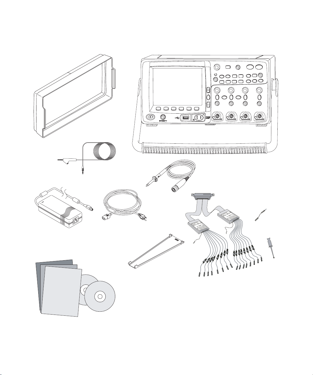
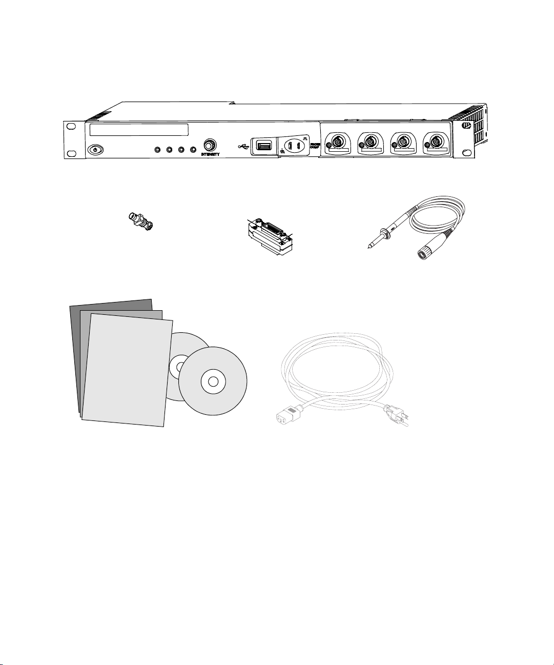
To inspect package contents
✔ Inspect the shipping container for damage.
✔ Verify that you received the following items and any optional
Getting Started 1
If your shipping container appears to be damaged, keep the
shipping container or cushioning material until you have
inspected the contents of the shipment for completeness and
have checked the oscilloscope mechanically and electrically.
accessories you may have ordered:
• 6000 Series Oscilloscope
• Front-panel cover (6000A Series only)
• Power cord (see Table 8 on page 35)
• Models with Option BAT only: Power Supply (P/N
0950-4866)
• LAN Crossover Cable 5061-0701 (6000L Series only)
• GPIB cable extender P/N 5183-0803 (6000L Series only)
• 50 ohm feedthrough termination adapter P/N 0960-0301
(Qty. 4 supplied with DSO6014L only)
• Oscilloscope probes
• Two probes for 2-channel models
• Four probes for 4-channel models
• 10074C probes for 100 MHz bandwidth models
• 10073C probes for all other models
• Manuals
• User’s Guide
• Service Guide
• Programmer’s Quick Start Guide
• CD-ROM containing the Programmer’s Reference Guide
• Automation-Ready Software CD-ROM
• MSO Models: digital probe kit (54620-68701) and digital
cable guide (54684-42301)
6000 Series Oscilloscope User’s Guide 21

1Getting Started
Front-panel cover
Manuals and
CD-ROMs
Power cord
(Part numbers given
on page 35)
*Digital Probe Kit contains:
54620-61801 16-channel cable (qty 1)
5959-9334 2-inch probe ground leads (qty 5)
5090-4833 Grabber (qty 20)
Digital probe replacement parts are listed on page 333
6000A Series
Oscilloscope
Oscilloscope probes
10073C or 10074C
(Qty 2 or 4)
Digital Probe Kit*
(MSO models only)
Digital
cable guide
(MSO models only)
Figure 1 Package contents for 6000A Series AC-powered oscilloscopes
22 6000 Series Oscilloscope User’s Guide
Front-panel cover
Getting Started 1
6000A Series Option BAT
Oscilloscope
Oscilloscope probes
10073C or 10074C
(Qty 2 or 4)
*Digital Probe Kit contains:
54620-61801 16-channel cable (qty 1)
5959-9334 2-inch probe ground leads (qty 5)
5090-4833 Grabber (qty 20)
Digital probe replacement parts are listed in the
Reference chapter.
AC/DC power adapter
Ground wire
(see Power Cords
Manuals and
CD-ROMs
Power cord
table)
Digital cable guide
(MSO models only)
Figure 2 Package contents for 6000A Series battery-powered oscilloscopes (Option BAT)
Digital Probe Kit*
(MSO models only)
6000 Series Oscilloscope User’s Guide 23
1Getting Started
50 ohm feedthrough
termination adapter
P/N 0960-0301, Qty. 4
6000L Series Oscilloscope
GPIB cable extender
P/N 5183-0803
Manuals and
CD-ROMs
Oscilloscope Probes
10073C or 10074C
Qty. 4
Power cord
(Part numbers given
on page 35)
Figure 3 Package contents for 6000L Series oscilloscopes
24 6000 Series Oscilloscope User’s Guide

Getting Started 1
Tabl e 6 Accessories available
Model Description
N2918A 6000 Series Oscilloscope Evaluation Kit
1180CZ Testmobile oscilloscope cart (requires N2919A adapter kit)
N2919A Testmobile Adapter Kit
N2916A 6000A Rackmount Kit
54684-44101 Front-panel cover
N2605A-097 USB cable
10833A GPIB cable, 1 m long
10073C Passive probe, 10:1, 500 MHz, 1.5 m
10074C Passive probe, 10:1, 100 MHz, 1.5 m
54620-68701 Digital probe kit
54684-42301 Digital probe cable guide (cable tray)
0960-0301 50-Ohm Feedthrough
1130A InfiniiMax 1.5 GHz InfiniiMax differential probe amplifier
1141A InfiniiMax 200 MHz differential probe (with 1142A power supply)
1144A 800 MHz active probe (with 1142A power supply)
1145A 750 MHz 2-channel active probe (with 1142A power supply)
1156A 1.5 GHz active probe
01650-61607 16:16 logic cable and terminator (use with header on target sys.)
54620-68701 16:2 x 8 logic input probe assembly (standard with MSO models)
1146A 100 kHz Current probe, AC/DC
10070C 1:1 Passive Probe
10072A Fine-pitch probe kit
10075A 0.5 mm IC clip kit
10076A 100:1, 4 kV 250 MHz probe
E2613B 0.5 mm Wedge probe adapter, 3-signal, qty 2
E2614A 0.5 mm Wedge probe adapter, 8-signal, qty 1
E2615B 0.65 mm Wedge probe adapter, 3-signal, qty 2
E2616A 0.65 mm Wedge probe adapter, 8-signal, qty 1
E2643A 0.5 mm Wedge probe adapter, 16-signal, qty 1
E2644A 0.65 mm Wedge probe adapter, 16-signal, qty 1
N2772A 20 MHz differential probe
N2773A Power supply for N2772A
N2774A 50 MHz current probe AC/DC
N2775A Power supply for N2774A
You can search for these parts at www.agilent.com or at www.parts.agilent.com.
6000 Series Oscilloscope User’s Guide 25
1Getting Started
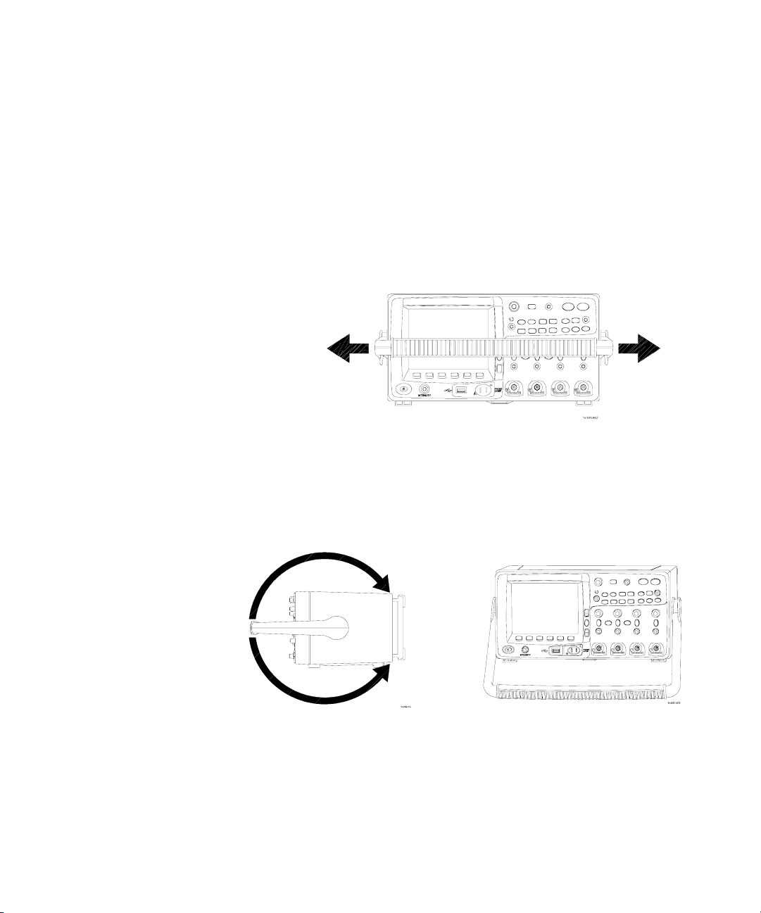
To adjust the 6000A Series handle
You can use the oscilloscope’s handle for carrying the
instrument, or you can use it as a stand to tilt the instrument up
for easier viewing of its display.
1 Grasp the handle hubs on each side of the instrument and
pull the hubs out until they stop.
26 6000 Series Oscilloscope User’s Guide
2 Without releasing the hubs, rotate the handle to the desired
position. Then release the hubs. Continue rotating the handle
until it clicks into a set position.

To mount the oscilloscope in a rack
The 6000 Series oscilloscopes can be mounted into Electronic
Industries Association (EIA) standard 19-inch (487-mm) rack
cabinets.
To mount the 6000A Series oscilloscope in a rack
Purchase and install the N2916A rack mount kit. Instructions
are included in the kit.
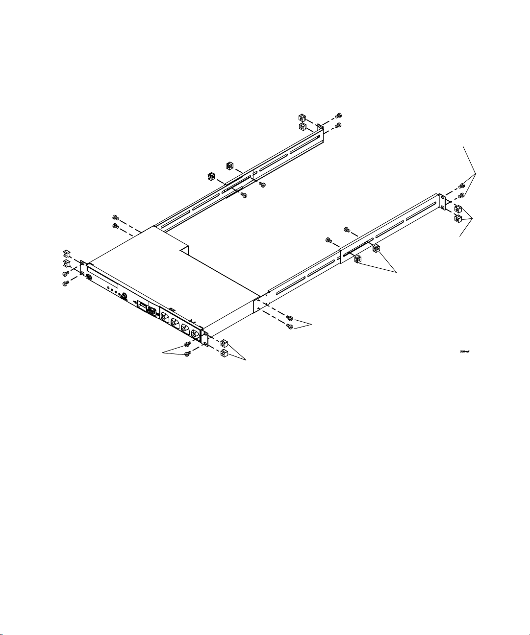
To mount the 6000L Series oscilloscope in a rack
The 6000L Series oscilloscope is supplied with all necessary
hardware for installation into a standard EIA 19-inch rack.
Tabl e 7 Rack Mount Hardware Supplied
Getting Started 1
Quantity Description Agilent Part
2 Front Extender Support D6104-01201
2 Rear Extender Support D6104-01202
4 Rear Extender Screw (M3 x 6 mm) 0515-0430
4 Dress Screw (10-32 x 0.0625) 0570-1577
8 Rail Screw (10-32 x 0.375) 2680-0281
12 Clip-nut (10-32) 0590-0804
Number
Tools required (not supplied)
• #2 Phillips screwdriver
• T20 Torx driver
• T10 Torx driver
6000 Series Oscilloscope User’s Guide 27
1Getting Started
Step 4
If needed
Step 1,
step 5
Step 3
If needed
1 Loosely attach the Front Extender Supports to the Rear
Extender Supports with four (4) clip-nuts and four (4) of the
10-32 x 0.375 Rail Screws. (The screws require a Torx T20
driver.) Choose the correct set of slots in the supports such
that their overall length is approximately correct for the
depth of your cabinet.
28 6000 Series Oscilloscope User’s Guide
Step 2

Getting Started 1
2 Fasten the Rack Mount Extenders to the oscilloscope chassis
with the four (4) M3 x 6 mm screws, using a Torx T10 driver
as follows:
NOTE
The sets of holes in the Rack Mount Extenders are slightly offset. This was
done to ensure that the Rack Mount Extenders are attached to the
oscilloscope at the correct points so that the oscilloscope’s ventilation
area is not obscured. The holes in the Rack Mount Extenders will align
with the correct holes in the oscilloscope and the screws will go in easily.
Do not force the screws into the wrong holes.
a Attach a Rack Mount Extender to the left side of the
oscilloscope using two (2) of the M3 x 6 mm screws in the
inner set of holes on the Rack Mount Extender.
Use inner
holes in
extender
Use outer
holes in
extender
b Attach the other Rack Mount Extender to the right side of
the oscilloscope using two (2) of the M3 x 6 mm screws in
the outer set of holes on the rack mount extender.
3 Place the instrument in the rack. Install the four (4)
10-32 x 0.625 Dress Screws in the chassis front ears to secure
the front of the instrument to the rack. Use the Phillips
screwdriver.
4 Align the ears in the Rear Mount Extenders with the correct
set of holes in the rear of the rack and secure the Rack Mount
6000 Series Oscilloscope User’s Guide 29

1Getting Started
Ventilation requirements
Extenders to the rack using the four (4) remaining
10-32 x 0.375 Rail Screws. Use the Torx T20 driver.
5 Securely attach the Rear Extender Supports to the Front
Extender Supports by tightening the four (4) 10-32 x 0.375
Rail Screws screws that you loosely attached in step 1.
The air intake and exhaust areas must be free from
obstructions. Unrestricted air flow is required for proper
cooling.
6000A Ventilation Requirements
The fan draws air in from underneath the oscilloscope and
pushes it out behind the oscilloscope. Always ensure that the
air intake and exhaust areas are free from obstructions.
When using the oscilloscope in a bench-top setting, provide at
least 4" (100 mm) clearance behind and above the oscilloscope
for proper cooling.
6000L Ventilation Requirements
The fan draws air from the left and pushes it to the right.
Ensure that air flow is not obstructed.
30 6000 Series Oscilloscope User’s Guide
 Loading...