


8510XF Network Analyzer Systems
E7340A & E7342A (2 to 85 GHz)
E7350A & E7352A (2 to 110 GHz)
Operating and Service
Manual
Agilent Part Number: E7350-90001
Printed in USA
Print Date: April 2002
Supersedes: June 2001

Notice
The information contained in this document is subject to change without
notice.
Agilent Technologies makes no warranty of any kind with regard to this
material, including, but not limited to, the implied warranties of
merchantability and fitness for a particular purpose. Agilent Technologies
shall not be liable for errors contained herein or for incidental or
consequential damages in connection with the furnishing, performance, or
use of this material.
Agilent Technologies assumes no responsibility for the use or reliability of
its software on equipment that is not furnished by Agilent Technologies.
This document contains proprietary information which is protected by
copyright. All rights are reserved. No part of this document may be
photocopied, reproduced, or translated to another language without prior
written consent of Agilent Technologies.
Restricted Rights Legend
Use, duplication, or disclosure by the U.S. Government is subject to
restrictions as set forth in subparagraph (c)(1)(ii) of the Rights in Technical
Data and Computer Software clause at DFARS 252.227-7013 for DOD
agencies, and subparagraphs (c)(1) and (c)(2) of the Commercial Computer
Software Restricted Rights clause at FAR 52.227-19 for other agencies.
Hewlett-Packard to Agilent Technologies Transition
This documentation supports a product that previously shipped under the
Hewlett-Packard company brand name. The brand name has now been
changed to Agilent Technologies. The two products are functionally
identical, only our name has changed. This document still includes
references to Hewlett-Packard products, some of which have been
transitioned to Agilent Technologies.
Windows ® is a registered copyright of Microsoft corporation.
© Copyright 1998, 2001, 2002 Agilent Technologies, Inc.
ii 8510XF Network Analyzer Systems

What You’ll Find in This Manual…
Chapter 1 • Introduction to the 8510XF
Chapter 2 • How to install the system
Chapter 3 • How to use the system to make measurements
Chapter 4 • How to verify the performance of the system
Chapter 5 • How to maintain the system
Chapter 6 • How to order replacement parts
Chapter 7 • How to find information about menus, softkeys, and commands
8510XF Network Analyzer Systems iii

Warranty
Certification Agilent Technologies certifies that this product met its published
specifications at the time of shipment from the factory. Agilent Technologies
further certifies that its calibration measurements are traceable to the
United States National Institute of Standards and Technology (NIST,
formerly NBS), to the extent allowed by the Institute’s calibration facility,
and to the calibration facilities of other International Standards
Organization members.
DOCUMENTATION WARRANTY
THE MATERIAL CONTAINED IN THIS DOCUMENT IS
PROVIDED "AS IS," AND IS SUBJECT TO BEING CHANGED,
WITHOUT NOTICE, IN FUTURE EDITIONS. FURTHER, TO
THEMAXIMUMEXTENTPERMITTEDBYAPPLICABLELAW,
AGILENTDISCLAIMSALLWARRANTIES,EITHEREXPRESS
OR IMPLIED WITH REGARD TO THIS MANUAL AND ANY
INFORMATIONCONTAINEDHEREIN,INCLUDINGBUTNOT
LIMITED TO THE IMPLIED WARRANTIES OF
MERCHANTABILITY AND FITNESS FOR A PARTICULAR
PURPOSE. AGILENT SHALL NOT BE LIABLE FOR ERRORS
OR FOR INCIDENTAL OR CONSEQUENTIAL DAMAGES IN
CONNECTION WITH THE FURNISHING, USE, OR
PERFORMANCE OF THIS DOCUMENT OR ANY
INFORMATION CONTAINED HEREIN. SHOULD AGILENT
ANDTHEUSERHAVEASEPARATEWRITTENAGREEMENT
WITH WARRANTY TERMS COVERING THE MATERIAL IN
THIS DOCUMENT THAT CONFLICT WITH THESE TERMS,
THE WARRANTY TERMS IN THE SEPARATE AGREEMENT
WILL CONTROL.
Assistance Product maintenance agreements and other customer assistance agreements
are available for Agilent Technologies products.
For assistance, call your local Agilent Technologies office (see“Contacting
Agilent”)
iv8510XF Network Analyzer Systems

Contacting Agilent
Online assistance: www.agilent.com/find/assist
United States
(tel) 1 800 452 4844
New Zealand
(tel) 0 800 738 378
(fax) (+64) 4 495 8950
Malaysia
(tel) 1 800 828 848
(fax) 1 800 801 664
Taiwan
(tel) 0800-047-866
(fax) (886) 2 25456723
Latin America
(tel) (305) 269 7500
(fax) (305) 269 7599
Japan
(tel) (+81) 426 56 7832
(fax) (+81) 426 56 7840
Philippines
(tel) (632) 8426802
(tel) (
PLDT subscriber only):
1 800 16510170
(fax) (632) 8426809
(fax) (
PLDT subscriber only):
1 800 16510288
People’s Republic of
China
(tel) (preferred):
800-810-0189
(tel) (alternate):
10800-650-0021
(fax) 10800-650-0121
Canada
(tel) 1 877 894 4414
(fax) (905) 282-6495
Australia
(tel) 1 800 629 485
(fax) (+61) 3 9210 5947
Thailand
(tel) outside Bangkok:
(088) 226 008
(tel) within Bangkok:
(662) 661 3999
(fax) (66) 1 661 3714
India
(tel) 1-600-11-2929
(fax) 000-800-650-1101
Europe
(tel) (+31) 20 547 2323
(fax) (+31) 20 547 2390
Singapore
(tel) 1 800 375 8100
(fax) (65) 836 0252
Hong Kong
(tel) 800 930 871
(fax) (852) 2506 9233
8510XF Network Analyzer Systems v

Safety and Regulatory Information
Safety and Regulatory Information
Review this product and related documentation to familiarize yourself with
safety markings and instructions before you operate the instrument. This
product has been designed and tested in accordance with international
standards.
WARNING The WARNING notice denotes a hazard. It calls attention to a procedure,
practice, or the like, that, if not correctly performed or adhered to, could result
in personal injury. Do not proceed beyond a WARNING notice until the
indicated conditions are fully understood and met.
CAUTION The CAUTION notice denotes a hazard. It calls attention to an operating
procedure, practice, or the like, which, if not correctly performed or adhered
to, could result in damage to the product or loss of important data. Do not
proceed beyond a CAUTION notice until the indicated conditions are fully
understood and met.
vi 8510XF Network Analyzer Systems

Instrument Markings
Safety and Regulatory Information
When you see this symbol on your instrument, you should refer to the instrument’s
!
instruction manual for important information.
This symbol indicates hazardous voltages.
The laser radiation symbol is marked on products that have a laser output.
This symbol indicates that the instrument requires alternating current (ac) input.
The C-Tick mark is a registered trademark of the Australian Spectrum Agency.
The CE mark is a registered trademark of the European Community. If it is
accompanied by a year, it indicates the year the design was proven.
The CSA mark is a registered trademark of the Canadian Standards Association.
Safety Requirements
Safety Earth Ground
1SM1-A This textindicates that the instrument is an Industrial Scientific and Medical Group 1
Class A product (CISPER 11, Clause 4).
This ISM device complies with Canadian ICES-001.
Cet apppareil ISM est conforme a la norme NMB du Canada.
This symbol indicates that the power line switch is ON.
This symbol indicates that the power line switch is OFF or in STANDBY position.
This product has been designed and tested in accordance with the IEC
Publication 1010, Safety Requirements for Electronic Measuring Apparatus,
and has been supplied in a safe condition. The instruction documentation
contains information and warnings which must be followed by the user to
ensure safe operation and maintain the product in a safe condition.
This is a Safety Class I product (provided with a protective earthing
terminal). An uninterruptible safety earth ground must be provided from the
main power source to the product input wiring terminals, power cord, or
supplied power cord set. Whenever it is likely that the protection has been
impaired, the product must be made inoperative and secured against any
unintended operation.
8510XF Network Analyzer Systems vii
Safety and Regulatory Information
BeforeApplying Power Verify that the product is configured to match the available main power
source as described in the input power configuration instructions in this
manual. If this product is to be powered by autotransformer, make sure the
common terminal is connected to the neutral (grounded) side of the ac power
supply.
WARNING Danger of explosion if battery is incorrectly replaced. Replace only with the
same or equivalent type recommended. Discard used batteries according to
manufacturers’s instructions.
NOTE Please refer to the 8510C On-Ssite Service Manual for additional
information (part number 08510-90282).
viii 8510XF Network Analyzer Systems

Typeface Conventions
Typeface Conventions
Italics • Used to emphasize important information:
Use this software only with the xxxxxX system.
• Used for the title of a publication:
Refer to the xxxxxX System-Level User’s Guide.
• Used to indicate a variable:
Type
LOAD BIN filename.
Instrument Display • Used to show on-screen prompts and messages that you will see on the
display of an instrument:
The xxxxxX will display the message
[Keycap] • Used for labeled keys on the front panel of an instrument or on a
computer keyboard:
Press
[Return].
CAL1 SAVED.
{Softkey} • Used for simulated keys that appear on an instrument display:
Press
{Prior Menu}.
User Entry • Used to indicate text that you will enter using the computer keyboard;
text shown in this typeface must be typed exactly as printed:
Type
LOAD PARMFILE
• Used for examples of programming code:
#endif // ifndef NO_CLASS
Path Name
Computer Display • Used to show messages, prompts, and window labels that appear on a
• Used for a subdirectory name or file path:
Edit the file
usr/local/bin/sample.txt
computer monitor:
The
Edit Parameterswindow will appear on the screen.
• Used for menus, lists, dialog boxes, and button boxes on a computer
monitor from which you make selections using the mouse or keyboard:
Double-click
EXIT to quit the program.
8510XF Network Analyzer Systems ix

Compliance with Standards
Compliance with Standards
Compliance with German Noise Requirements
This is to declare that this instrument is in conformance with the German
Regulation on Noise Declaration for Machines (Laermangabe nach der
Maschinenlaermrerordnung
−3.GSGV Deutschand).
Acoustic Noise Emission/Geraeuschemission
LpA <70 dB
Operator position
Normal position
per ISO 7779
LpA <70 dB
am Arbeitsplatz
normaler Betrieb
nach DIN 45635 t.19
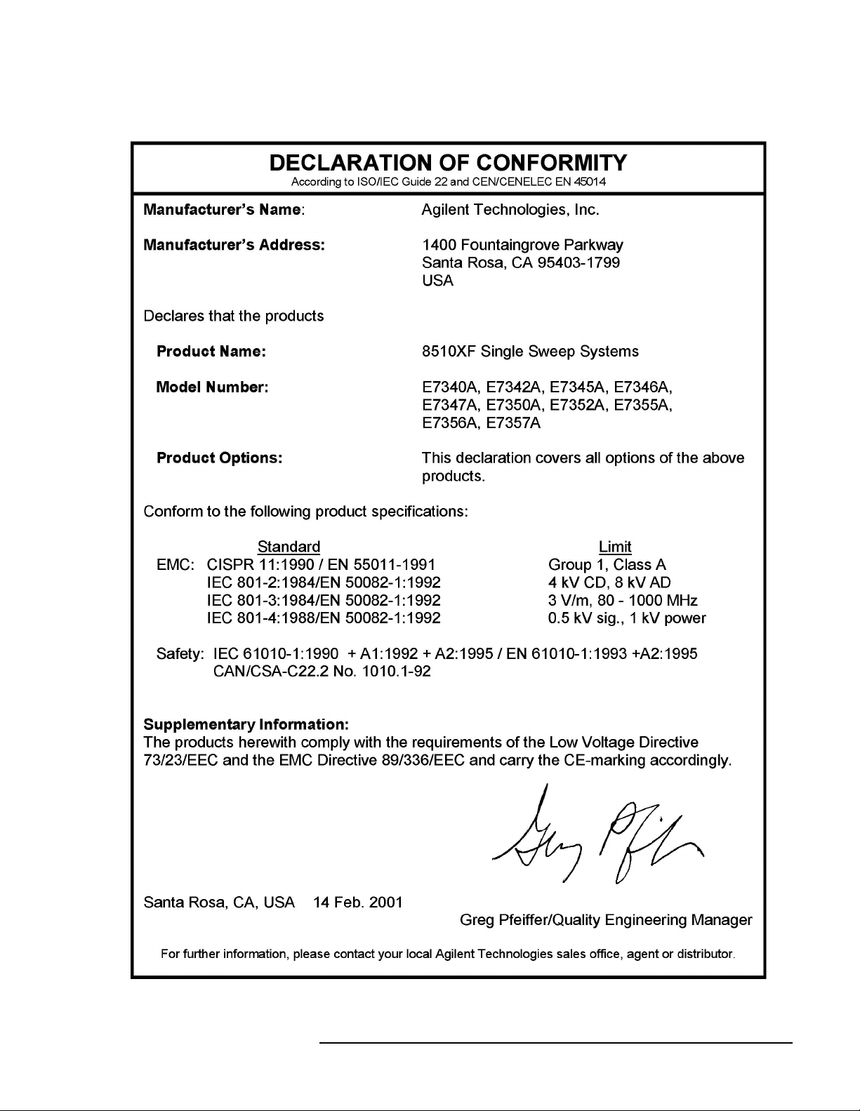
Compliance with EEC Directives
See the declaration of conformity on the following page.
x 8510XF Network Analyzer Systems
Compliance with Standards
8510XF Network Analyzer Systems xi

Compliance with Standards
xii 8510XF Network Analyzer Systems

Contents
Notice . . . . . . . . . . . . . . . . . . . . . . . . . . . . . . . . . . . . . . . . . . . . . . . . . . . . . ii
What You’ll Find in This Manual… . . . . . . . . . . . . . . . . . . . . . . . . . . . . . iii
Warranty . . . . . . . . . . . . . . . . . . . . . . . . . . . . . . . . . . . . . . . . . . . . . . . . . . . iv
Certification . . . . . . . . . . . . . . . . . . . . . . . . . . . . . . . . . . . . . . . . . . . . . iv
DOCUMENTATION WARRENTY . . . . . . . . . . . . . . . . . . . . . . . . . . . iv
Assistance . . . . . . . . . . . . . . . . . . . . . . . . . . . . . . . . . . . . . . . . . . . . . . . iv
Contacting Agilent . . . . . . . . . . . . . . . . . . . . . . . . . . . . . . . . . . . . . . . . . . . v
Safety and Regulatory Information . . . . . . . . . . . . . . . . . . . . . . . . . . . . . . vi
Safety Requirements . . . . . . . . . . . . . . . . . . . . . . . . . . . . . . . . . . . . . . vii
Safety Earth Ground . . . . . . . . . . . . . . . . . . . . . . . . . . . . . . . . . . . . . . vii
Before Applying Power . . . . . . . . . . . . . . . . . . . . . . . . . . . . . . . . . . viii
Typeface Conventions . . . . . . . . . . . . . . . . . . . . . . . . . . . . . . . . . . . . . . . ix
Compliance with Standards . . . . . . . . . . . . . . . . . . . . . . . . . . . . . . . . . . . . x
1. Introduction
Finding System Information . . . . . . . . . . . . . . . . . . . . . . . . . . . . . . . . . . 1-2
Sources of Information . . . . . . . . . . . . . . . . . . . . . . . . . . . . . . . . . . . 1-2
8510XF Network Analyzer Systems . . . . . . . . . . . . . . . . . . . . . . . . . . . 1-4
System Description . . . . . . . . . . . . . . . . . . . . . . . . . . . . . . . . . . . . . . . . . 1-5
Two Versions of the 8510XF . . . . . . . . . . . . . . . . . . . . . . . . . . . . . . 1-5
What’s Included . . . . . . . . . . . . . . . . . . . . . . . . . . . . . . . . . . . . . . . . 1-5
Frequency Limits . . . . . . . . . . . . . . . . . . . . . . . . . . . . . . . . . . . . . . . 1-5
Partial Systems . . . . . . . . . . . . . . . . . . . . . . . . . . . . . . . . . . . . . . . . . 1-5
Options . . . . . . . . . . . . . . . . . . . . . . . . . . . . . . . . . . . . . . . . . . . . . . . . . . 1-8
Option 005 (45 MHz to 2 GHz) . . . . . . . . . . . . . . . . . . . . . . . . . . . . 1-8
Option 006 (RF Passthrough) . . . . . . . . . . . . . . . . . . . . . . . . . . . . . . 1-8
Option 010 (Time Domain) . . . . . . . . . . . . . . . . . . . . . . . . . . . . . . . 1-9
Option 230 (Line Voltage) . . . . . . . . . . . . . . . . . . . . . . . . . . . . . . . . 1-9
Upgrade Paths . . . . . . . . . . . . . . . . . . . . . . . . . . . . . . . . . . . . . . . . . . . . 1-10
2. Installation
Site Preparation . . . . . . . . . . . . . . . . . . . . . . . . . . . . . . . . . . . . . . . . . . . . 2-2
Power Requirements . . . . . . . . . . . . . . . . . . . . . . . . . . . . . . . . . . . . . 2-2
Environmental Requirements . . . . . . . . . . . . . . . . . . . . . . . . . . . . . . 2-3
Receiving the System . . . . . . . . . . . . . . . . . . . . . . . . . . . . . . . . . . . . . . . 2-5
The System as Shipped . . . . . . . . . . . . . . . . . . . . . . . . . . . . . . . . . . . 2-5
Agilent Technologies Customer Engineering . . . . . . . . . . . . . . . . . . 2-5
In Case of Problems with the Shipment . . . . . . . . . . . . . . . . . . . . . . 2-5
Precautions . . . . . . . . . . . . . . . . . . . . . . . . . . . . . . . . . . . . . . . . . . . . . . . 2-9
Safe Installation . . . . . . . . . . . . . . . . . . . . . . . . . . . . . . . . . . . . . . . . 2-9
Electrostatic Discharge . . . . . . . . . . . . . . . . . . . . . . . . . . . . . . . . . . 2-10
System Voltages . . . . . . . . . . . . . . . . . . . . . . . . . . . . . . . . . . . . . . . 2-10
8510XF Network Analyzer Systems Operating and Service Manual Contents xiii

Test Port Inputs . . . . . . . . . . . . . . . . . . . . . . . . . . . . . . . . . . . . . . . . 2-10
Cleaning . . . . . . . . . . . . . . . . . . . . . . . . . . . . . . . . . . . . . . . . . . . . . 2-10
Unpacking the System . . . . . . . . . . . . . . . . . . . . . . . . . . . . . . . . . . . . . . 2-11
Tools Required . . . . . . . . . . . . . . . . . . . . . . . . . . . . . . . . . . . . . . . . 2-11
Basic System Configurations . . . . . . . . . . . . . . . . . . . . . . . . . . . . . . . . . 2-17
Installing the Work Surface . . . . . . . . . . . . . . . . . . . . . . . . . . . . . . . 2-20
Millimeter-Wave Controller . . . . . . . . . . . . . . . . . . . . . . . . . . . . . . . . . 2-23
LEDs . . . . . . . . . . . . . . . . . . . . . . . . . . . . . . . . . . . . . . . . . . . . . . . . 2-23
Connectors (Port 1) . . . . . . . . . . . . . . . . . . . . . . . . . . . . . . . . . . . . . 2-24
Connectors (Port 2) . . . . . . . . . . . . . . . . . . . . . . . . . . . . . . . . . . . . . 2-24
GPIB Address Switch . . . . . . . . . . . . . . . . . . . . . . . . . . . . . . . . . . . 2-25
Fuse . . . . . . . . . . . . . . . . . . . . . . . . . . . . . . . . . . . . . . . . . . . . . . . . . 2-25
Test Heads . . . . . . . . . . . . . . . . . . . . . . . . . . . . . . . . . . . . . . . . . . . . . . . 2-26
Connector Positions . . . . . . . . . . . . . . . . . . . . . . . . . . . . . . . . . . . . 2-26
Power Supply Inputs . . . . . . . . . . . . . . . . . . . . . . . . . . . . . . . . . . . . 2-26
Illustrations . . . . . . . . . . . . . . . . . . . . . . . . . . . . . . . . . . . . . . . . . . . 2-26
Test Ports . . . . . . . . . . . . . . . . . . . . . . . . . . . . . . . . . . . . . . . . . . . . . 2-27
Controller / Test Head Interconnections . . . . . . . . . . . . . . . . . . . . . . . . 2-28
Systems With Option 005 . . . . . . . . . . . . . . . . . . . . . . . . . . . . . . . . 2-28
Instruments Without Option 005 . . . . . . . . . . . . . . . . . . . . . . . . . . . 2-30
Cable List . . . . . . . . . . . . . . . . . . . . . . . . . . . . . . . . . . . . . . . . . . . . . . . . 2-32
Duplicate Listings . . . . . . . . . . . . . . . . . . . . . . . . . . . . . . . . . . . . . . 2-32
Turning On the System . . . . . . . . . . . . . . . . . . . . . . . . . . . . . . . . . . . . . 2-38
System Operational Test . . . . . . . . . . . . . . . . . . . . . . . . . . . . . . . . . . . . 2-39
Test Procedure . . . . . . . . . . . . . . . . . . . . . . . . . . . . . . . . . . . . . . . . . 2-40
Operating Notes . . . . . . . . . . . . . . . . . . . . . . . . . . . . . . . . . . . . . . . . . . . 2-42
3. Operation
8510XF Operating System . . . . . . . . . . . . . . . . . . . . . . . . . . . . . . . . . . . 3-2
Checking the Operating System . . . . . . . . . . . . . . . . . . . . . . . . . . . . 3-2
Measurement Calibration . . . . . . . . . . . . . . . . . . . . . . . . . . . . . . . . . . . . . 3-6
Why Calibration Is Essential . . . . . . . . . . . . . . . . . . . . . . . . . . . . . . . 3-6
When to Repeat the Calibration . . . . . . . . . . . . . . . . . . . . . . . . . . . . 3-6
Calibration Techniques . . . . . . . . . . . . . . . . . . . . . . . . . . . . . . . . . . . 3-7
Types of Calibration Kits . . . . . . . . . . . . . . . . . . . . . . . . . . . . . . . . . 3-7
Calibration Procedure . . . . . . . . . . . . . . . . . . . . . . . . . . . . . . . . . . . . . . . 3-9
Load Calibration Constants . . . . . . . . . . . . . . . . . . . . . . . . . . . . . . . . 3-9
Set Up the Analyzer . . . . . . . . . . . . . . . . . . . . . . . . . . . . . . . . . . . . . 3-9
Connect and Measure the Calibration Standards . . . . . . . . . . . . . . 3-10
Choosing Calibration Standards . . . . . . . . . . . . . . . . . . . . . . . . . . . . . . 3-11
Connector Sex . . . . . . . . . . . . . . . . . . . . . . . . . . . . . . . . . . . . . . . . . 3-11
Offset Shorts . . . . . . . . . . . . . . . . . . . . . . . . . . . . . . . . . . . . . . . . . . 3-11
Banded Standards . . . . . . . . . . . . . . . . . . . . . . . . . . . . . . . . . . . . . . 3-12
Non-Banded Standards . . . . . . . . . . . . . . . . . . . . . . . . . . . . . . . . . . 3-12
Calibration Types . . . . . . . . . . . . . . . . . . . . . . . . . . . . . . . . . . . . . . . . . . 3-13
S22 1-Port . . . . . . . . . . . . . . . . . . . . . . . . . . . . . . . . . . . . . . . . . . . . 3-16
Standard Types . . . . . . . . . . . . . . . . . . . . . . . . . . . . . . . . . . . . . . . . . . . 3-20
Contents xiv 8510XF Network Analyzer Systems Operating and Service Manual

Standards Already Described . . . . . . . . . . . . . . . . . . . . . . . . . . . . . 3-20
Other Standards . . . . . . . . . . . . . . . . . . . . . . . . . . . . . . . . . . . . . . . 3-20
Port Power . . . . . . . . . . . . . . . . . . . . . . . . . . . . . . . . . . . . . . . . . . . . . . . 3-28
RF Power . . . . . . . . . . . . . . . . . . . . . . . . . . . . . . . . . . . . . . . . . . . . . . . 3-30
RF Power Configuration . . . . . . . . . . . . . . . . . . . . . . . . . . . . . . . . . 3-30
LO Power . . . . . . . . . . . . . . . . . . . . . . . . . . . . . . . . . . . . . . . . . . . . . . . 3-36
LO Power Configuration . . . . . . . . . . . . . . . . . . . . . . . . . . . . . . . . 3-36
LO Power Settings . . . . . . . . . . . . . . . . . . . . . . . . . . . . . . . . . . . . . 3-37
Service . . . . . . . . . . . . . . . . . . . . . . . . . . . . . . . . . . . . . . . . . . . . . . . . . . 3-38
85102 Service . . . . . . . . . . . . . . . . . . . . . . . . . . . . . . . . . . . . . . . . . 3-38
Leveling Settings . . . . . . . . . . . . . . . . . . . . . . . . . . . . . . . . . . . . . . 3-41
IF Frequency . . . . . . . . . . . . . . . . . . . . . . . . . . . . . . . . . . . . . . . . . . . . . 3-42
Alternative 1.0 mm Calibrations . . . . . . . . . . . . . . . . . . . . . . . . . . . . . . 3-43
Broadband Standards . . . . . . . . . . . . . . . . . . . . . . . . . . . . . . . . . . . 3-43
Operation Using a Wafer Probe Station . . . . . . . . . . . . . . . . . . . . . . . . 3-46
System Configuration . . . . . . . . . . . . . . . . . . . . . . . . . . . . . . . . . . . 3-46
Available Equipment . . . . . . . . . . . . . . . . . . . . . . . . . . . . . . . . . . . 3-47
Device Connections . . . . . . . . . . . . . . . . . . . . . . . . . . . . . . . . . . . . 3-47
Types of Probe Stations . . . . . . . . . . . . . . . . . . . . . . . . . . . . . . . . . 3-47
4. Performance Verification
When to Verify . . . . . . . . . . . . . . . . . . . . . . . . . . . . . . . . . . . . . . . . . 4-2
Materials Required . . . . . . . . . . . . . . . . . . . . . . . . . . . . . . . . . . . . . 4-3
Calibration and Frequency Ranges . . . . . . . . . . . . . . . . . . . . . . . . . . 4-3
Verification Setup . . . . . . . . . . . . . . . . . . . . . . . . . . . . . . . . . . . . . . . . . 4-5
General Preparation . . . . . . . . . . . . . . . . . . . . . . . . . . . . . . . . . . . . . 4-5
Software Installation . . . . . . . . . . . . . . . . . . . . . . . . . . . . . . . . . . . . . 4-5
Software Configuration . . . . . . . . . . . . . . . . . . . . . . . . . . . . . . . . . . 4-6
Verification Procedures . . . . . . . . . . . . . . . . . . . . . . . . . . . . . . . . . . . . . 4-9
Low Band Verification (< 50 GHz) . . . . . . . . . . . . . . . . . . . . . . . . . 4-9
CW Frequency Accuracy Test . . . . . . . . . . . . . . . . . . . . . . . . . . . . . . . 4-14
Materials Required . . . . . . . . . . . . . . . . . . . . . . . . . . . . . . . . . . . . . 4-14
Procedure . . . . . . . . . . . . . . . . . . . . . . . . . . . . . . . . . . . . . . . . . . . . 4-14
Performance Test Record . . . . . . . . . . . . . . . . . . . . . . . . . . . . . . . . 4-16
5. System Maintenance
Electrostatic Discharge . . . . . . . . . . . . . . . . . . . . . . . . . . . . . . . . . . . . . . 5-2
1.0 mm Connector Care . . . . . . . . . . . . . . . . . . . . . . . . . . . . . . . . . . . . . 5-3
Detector Gain Calibration . . . . . . . . . . . . . . . . . . . . . . . . . . . . . . . . . . . . 5-6
Purpose of the Calibration . . . . . . . . . . . . . . . . . . . . . . . . . . . . . . . . 5-6
The Calibration Process . . . . . . . . . . . . . . . . . . . . . . . . . . . . . . . . . . 5-6
When to Calibrate . . . . . . . . . . . . . . . . . . . . . . . . . . . . . . . . . . . . . . . 5-6
Procedure . . . . . . . . . . . . . . . . . . . . . . . . . . . . . . . . . . . . . . . . . . . . . 5-7
Conversion Loss Calibration . . . . . . . . . . . . . . . . . . . . . . . . . . . . . . . . . . 5-8
Purpose of the Calibration . . . . . . . . . . . . . . . . . . . . . . . . . . . . . . . . 5-8
The Calibration Process . . . . . . . . . . . . . . . . . . . . . . . . . . . . . . . . . . 5-8
When to Calibrate . . . . . . . . . . . . . . . . . . . . . . . . . . . . . . . . . . . . . . . 5-8
Agilent Technologies Customer Engineering . . . . . . . . . . . . . . . . . . 5-8
8510XF Network Analyzer Systems Operating and Service Manual Contents xv

Theory of Operation . . . . . . . . . . . . . . . . . . . . . . . . . . . . . . . . . . . . . . . . 5-9
Signal Separation . . . . . . . . . . . . . . . . . . . . . . . . . . . . . . . . . . . . . . . 5-9
Frequency Control . . . . . . . . . . . . . . . . . . . . . . . . . . . . . . . . . . . . . . 5-10
The Leveling Loop . . . . . . . . . . . . . . . . . . . . . . . . . . . . . . . . . . . . . 5-15
Level Calibration . . . . . . . . . . . . . . . . . . . . . . . . . . . . . . . . . . . . . . . 5-18
LO Levels . . . . . . . . . . . . . . . . . . . . . . . . . . . . . . . . . . . . . . . . . . . . 5-19
System Block Diagrams . . . . . . . . . . . . . . . . . . . . . . . . . . . . . . . . . . . . 5-21
110 GHz Systems . . . . . . . . . . . . . . . . . . . . . . . . . . . . . . . . . . . . . . 5-21
Troubleshooting . . . . . . . . . . . . . . . . . . . . . . . . . . . . . . . . . . . . . . . . . . . 5-37
Cycle Power . . . . . . . . . . . . . . . . . . . . . . . . . . . . . . . . . . . . . . . . . . 5-37
Hardware Configuration Check . . . . . . . . . . . . . . . . . . . . . . . . . . . . 5-37
Firmware Configuration Check . . . . . . . . . . . . . . . . . . . . . . . . . . . . 5-38
6. Replaceable Parts
Parts Listed . . . . . . . . . . . . . . . . . . . . . . . . . . . . . . . . . . . . . . . . . . . . 6-2
How to Order . . . . . . . . . . . . . . . . . . . . . . . . . . . . . . . . . . . . . . . . . . . 6-2
Frequency Ranges . . . . . . . . . . . . . . . . . . . . . . . . . . . . . . . . . . . . . . . 6-2
Categorization of Components . . . . . . . . . . . . . . . . . . . . . . . . . . . . . 6-3
110 GHz Systems . . . . . . . . . . . . . . . . . . . . . . . . . . . . . . . . . . . . . . . . . . 6-4
Complete System . . . . . . . . . . . . . . . . . . . . . . . . . . . . . . . . . . . . . . . 6-4
85 GHz Systems . . . . . . . . . . . . . . . . . . . . . . . . . . . . . . . . . . . . . . . . . . . 6-7
Complete System . . . . . . . . . . . . . . . . . . . . . . . . . . . . . . . . . . . . . . . 6-7
Millimeter-Wave Controller . . . . . . . . . . . . . . . . . . . . . . . . . . . . . . . . . 6-10
7. Menus & Commands
Menu Maps . . . . . . . . . . . . . . . . . . . . . . . . . . . . . . . . . . . . . . . . . . . . . . . 7-2
New GPIB Commands . . . . . . . . . . . . . . . . . . . . . . . . . . . . . . . . . . . . . 7-43
Unsupported GPIB Commands . . . . . . . . . . . . . . . . . . . . . . . . . . . . . . . 7-47
New Messages . . . . . . . . . . . . . . . . . . . . . . . . . . . . . . . . . . . . . . . . . . . . 7-49
Contents xvi 8510XF Network Analyzer Systems Operating and Service Manual

1 Introduction
In This Chapter...
Finding System Information, page 1-2
•
• 8510XF Network Analyzer Systems, page 1-4
• System Description, page 1-5
• Options, page 1-8
• Upgrade Paths, page 1-10
8510XF Network Analyzer Systems 1-1

Introduction
Finding System Information
Finding System Information
Sources of Information Documents provided with the 8510XF include the following:
Table 1-1 Documents Supplied with the System
Document Part Number Description
8510XF Operation and Service Manual E7350-90001 8510XF system manual
8510C Network Analyzer Manuals set 08510-90275 includes:
8510C Operating and Programming Manual 08510-90281 A detailed operator’s guide to the
8510C network analyzer
8510C Introductory User’s Guide 08510-90290 A brief introduction to functions,
menus, and measurement setups
for the 8510C network analyzer
8510C Quick Reference Guide 08510-90292 An abbreviated, pocket-sized guide
to codes, commands, and menu
maps for the 8510C network
analyzer
8510C Keyword Dictionary 08510-90280 A thorough presentation of codes,
commands, and menu maps for the
8510C network analyzer
8510C On-Site Service Manual 08510-90282 A detailed guide to maintenance
and troubleshooting for the 8510C
network analyzer
8360 Series Dedicated Source Manual set 08360-90138 includes:
83651B & 83621B Manuals 08360-90136
08360-90137
Troubleshooting and service
manuals for the RF source and LO
source
Another important document is the Operating and Service Manual for the
85059A 1.0 mm Precision Calibration and Verification Kit (the Agilent part
number of the manual is 85059-90003).
1-2 8510XF Network Analyzer Systems

Introduction
Finding System Information
Where to look The following table shows where to look first (and second) for particular
kinds of information.
Table 1-2 Primary and Secondary Information Sources
Subject First Source Other Sources
Installing the system Chapter 2 of this manual Chapter 9, 8510C On-Site Service Manual
Using menus Chapter 3 of this manual
(also see Chapter 7 for menu maps)
Using system functions Chapter 3 of this manual Chapter 5, 8510C Operating and Programming
Measurement calibration Chapter 3 of this manual Chapter 8, 8510C Operating and Programming
Verifying performance Chapter 4 of this manual Chapter 8, 8510C On-Site Service Manual
Maintenance Chapter 5 of this manual Chapters 7 & 10, 8510C On-Site Service Manual
Ordering replacement parts Chapter 6 of this manual Chapter 5, 8510C On-Site Service Manual
GPIB programming Chapter 7 of this manual Chapter 13, 8510C Operating and Programming
Basics of network analysis 8510C Introductory User’s Guide Chapter 3, 8510C Operating and Programming
Types of measurement 8510C Operating and Programming Manual:
• Chapter 9 (Transmission)
• Chapter 10 (Reflection)
• Chapter 11 (Time Domain)
• Chapter 12 (Power Domain)
Chapter 4, 8510C Operating and Programming
Manual
Manual
Manual
Also: Supplement to 8510C Operating and
Programming Manual (“Operator’s Check and
Routine Maintenance”)
Manual
Also: 8510C Quick Reference Guide
Also: 8510C Keyword Dictionary
Manual
Chapter 3 of this manual
Printing & plotting Chapter 6, 8510C Operating and Programming
Manual
Using the disk drive Chapter 7, 8510C Operating and Programming
Manual
8510XF Network Analyzer Systems 1-3
Introduction
8510XF Network Analyzer Systems
8510XF Network Analyzer Systems
The 8510XF is a vector network analyzer with an extremely wide frequency
range. It is available in two basic versions, with frequency ranges of
2 to 85 GHz and 2 to 110 GHz. Both ranges can be optionally extended
downward to 45 MHz.
The 8510XF uses the same test port connections throughout its entire range
of test frequencies. It is never necessary to make and break connections in
order to complete a test.
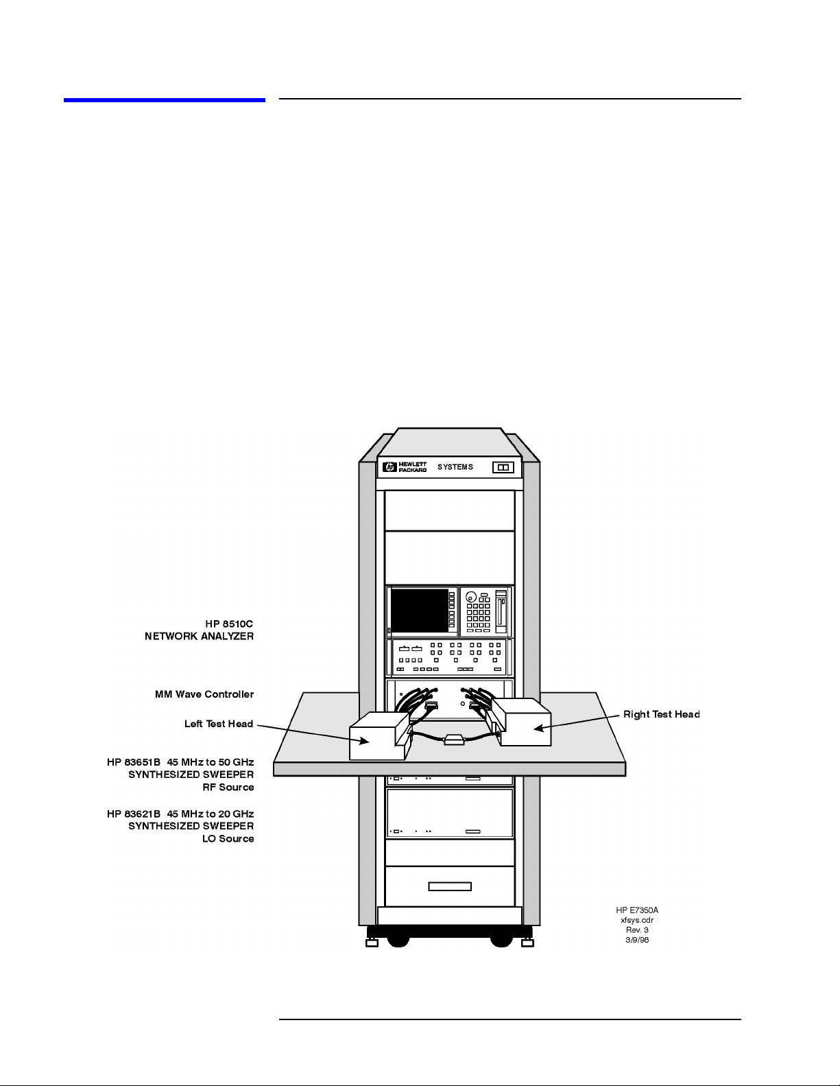
The illustration below shows the 8510XF configured for coaxial
measurement; the system can also be configured for on-wafer measurement
using a wafer probe test station.
Figure 1-1 8510XF Network Analyzer System
1-4 8510XF Network Analyzer Systems

System Description
Introduction
System Description
Two Versions of the 8510XF
The system is available in two basic versions, distinguished by their upper
frequency limits. The 85 GHz version is ordered as E7340A; the 110 GHz
version is ordered as E7350A.
What’s Included The major components of the 8510XF system are:
• Network analyzer, 8510C
• Synthesized RF source, 83651B
• Synthesized LO source, 83621B
• Millimeter-wave controller, E7341A
• Left test head, E7342L (85 GHz) or E7352L (110 GHz)
• Right test head, E7342R (85 GHz) or E7352R (110 GHz)
• 1.6 meter instrument rack (E3661A)
Frequency Limits As the list above indicates, the upper frequency limit of the system is
determined by the type of test head that is included in it.
The lower frequency limit of an 8510XF system is normally 2 GHz. With
Option 005 installed, the lower frequency limit is 45 MHz. (See “Options”
on page 1-8.)
Partial Systems Customers who already have the network analyzer and the sources can order
partial systems which omit those items. The partial systems are known as
millimeter-wave subsystems; the 85 GHz version is ordered as E7342A, and
the 110 GHz version is ordered as E7352A.
In addition, 8510XF upgrade kits are available for other Agilent test systems
(see “Upgrade Paths” on page 1-10).
8510XF Network Analyzer Systems 1-5
Introduction
System Description
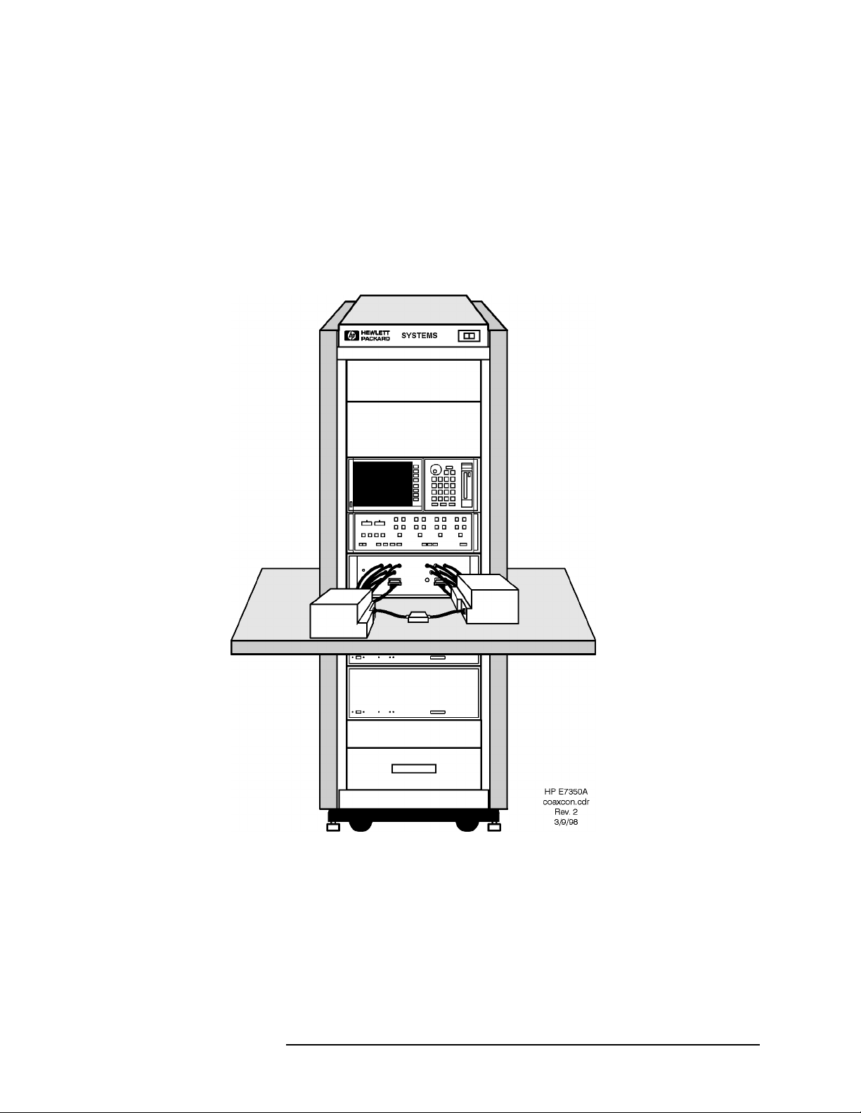
Coaxial Configuration When the 8510XF is configured for measurement through coaxial
connections, the network analyzer, the millimeter-wave controller, and the
RF and LO sources are all installed in the rack. The test heads are placed on
a work surface which is mounted below the millimeter-wave controller.
The test ports feature 1.0 mm coaxial connectors. The device under test is
typically connected to one test port directly, and to the other test port by way
of a coaxial cable (or it is connected to the ports through two coaxial cables).
Figure 1-2 8510XF, Configured for Coaxial Measurement
1-6 8510XF Network Analyzer Systems
Introduction
System Description
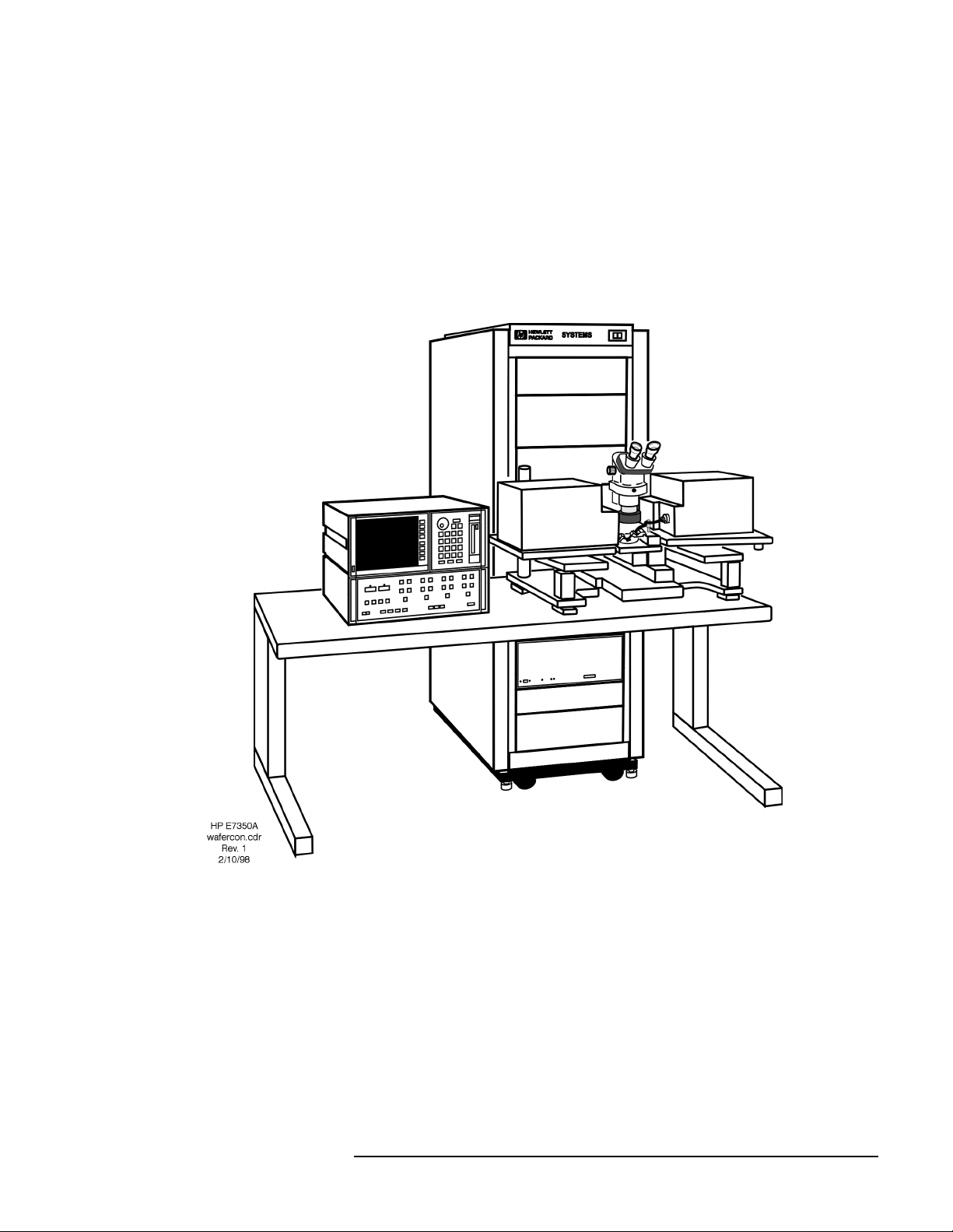
Wafer Probe
Configuration
For on-wafer measurements, it is usually best to remove the network
analyzer from the instrument rack, and place it on a table adjacent to the
probe station. This makes it easy to see and operate the analyzer.
No wafer probe station is supplied with the system; the illustration below
simply shows how the 8510XF combines with a typical probe station to
create an on-wafer measurement system.
Figure 1-3 8510XF, Configured for Wafer-Probe Measurement
8510XF Network Analyzer Systems 1-7
Introduction
Options
Options
Option 005
(45 MHz to 2 GHz)
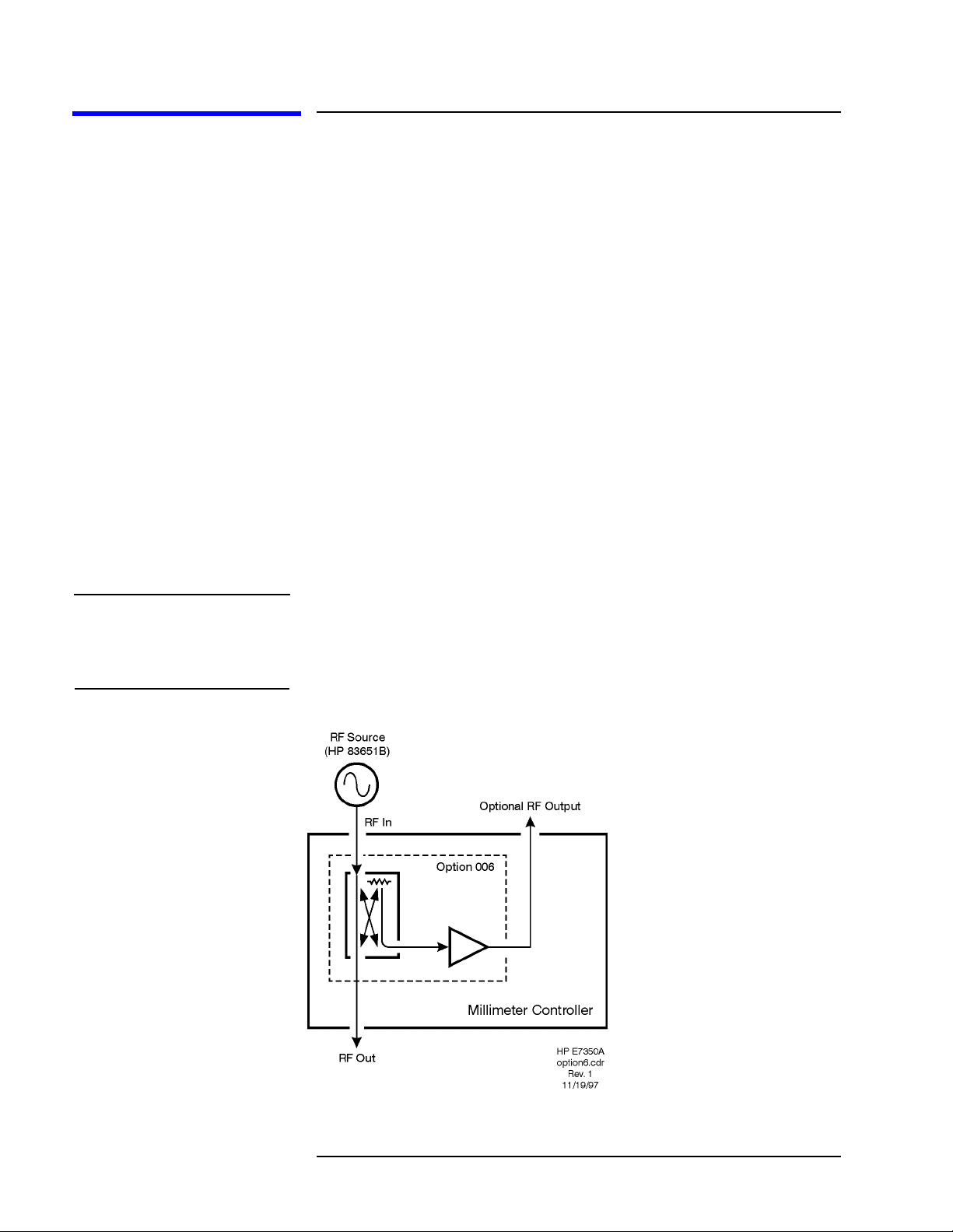
Option 006
(RF Passthrough)
NOTE The 8510XF firmware does not support multiple test sets. In order to use the
This option extends the lower limit of the 8510XF frequency range
downward to 45 MHz. The option is implemented by adding four
low-frequency mixers, which are dedicated to the .045 to 2 GHz frequency
range. These mixers are installed in the millimeter-wave controller.
This option adds a coupler, amplifier, and RF output connector to the
millimeter-wave controller. The purpose is to make the RF input to the
controller (which is supplied by the 83651B RF source) available as an
output, so that it can be routed to other devices or test sets.
The RF output on the rear panel of the millimeter-wave controller is a
2.4 mm coaxial connector. To supply this RF output to another test set, you
will need a 2.4 mm coaxial cable of adequate length (this cable is not
supplied with the 8510XF).
The system is shipped with a 50 Ω load attached to the RF output connector.
Option 006 RF output as the RF source for another test set, you must load
the standard 8510C firmware (from a diskette which is supplied with the
8510XF).
Figure 1-4 Option 006
1-8 8510XF Network Analyzer Systems

Introduction
Options
Option 010
(Time Domain)
NOTE Option 010 is available only for complete systems (E7340A and E7350A).
Option 230
This option makes it possible to use the 8510XF in time domain mode. The
option is implemented through modification of the network analyzer
operating system.
This option configures the 8510XF for 220/240 line voltage operation.
(Line Voltage)
8510XF Network Analyzer Systems 1-9

Introduction
Upgrade Paths
Upgrade Paths
Kits are available for upgrading another type of 8510C test system to an
8510XF system, as described below.
Upgrade Kits for the
85107A/B
Table 1-3 Contents of Upgrade Kits for the 85107A/B
An 85107A/B can be upgraded to an 8510XF, in either the 110 GHz version
(upgrade kit E7355A) or the 85 GHz version (upgrade kit E7345A).
Item Part#
Millimeter-wave controller E7341A
Left test head E7342L (85 GHz)
or E7352L (110 GHz)
Right test head E7342R (85 GHz)
or E7352R (110 GHz)
LO source 83621B
Rack flange kit for LO source 83621B #913
8510XF operating & service manual E7350-90001
E7345A/E7355A upgrade kit installation manual E7350-90003
8510XF system software on diskette E7340-10001
8 chips for expanding non-volatile memory in the 8510C 1818-4075
NOTE The upgrade kits for the 85107A/B can also be used for an 85109C system
which lacks Option 002. To upgrade an 85109C with Option 002, see the
upgrade kit described on page 1-12).
1-10 8510XF Network Analyzer Systems

Introduction
Upgrade Paths
Upgrade Kits for the
85106C/D
Table 1-4 Contents of Upgrade Kits for the 85106C/D
An 85106C/D can be upgraded to an 8510XF, in either the 110 GHz version
(upgrade kit E7356A) or the 85 GHz version (upgrade kit E7346A).
Item Part#
Millimeter-wave controller E7341A
Left test head E7342L (85 GHz)
or E7352L (110 GHz)
Right test head E7342R (85 GHz)
or E7352R (110 GHz)
RF source 83651B
Rack flange kit for RF source 83651B #913
8510XF operating & service manual E7350-90001
E7346A/E7356A upgrade kit installation manual E7350-90004
8510XF system software on diskette E7340-10001
8 chips for expanding non-volatile memory in the 8510C 1818-4075
8510XF Network Analyzer Systems 1-11

Introduction
Upgrade Paths
Upgrade Kits for the
85109C
(With Option 002)
Table 1-5 Contents of Upgrade Kits for the 85109C
An 85109C with Option 002 can be upgraded to an 8510XF, in either the
110 GHz version (upgrade kit E7357A) or the 85 GHz version (upgrade kit
E7347A).
Item Part#
Millimeter-wave controller E7341A
Left test head E7342L (85 GHz)
or E7352L (110 GHz)
Right test head E7342R (85 GHz)
or E7352R (110 GHz)
8510XF operating & service manual E7350-90001
E7347A/E7357A upgrade kit installation manual E7350-90005
8510XF system software on diskette E7340-10001
8 chips for expanding non-volatile memory in the 8510C 1818-4075
NOTE To upgrade an 85109C which lacks Option 002, see the upgrade kit
described on page 1-10.
1-12 8510XF Network Analyzer Systems

2 Installation
In This Chapter...
Site Preparation, page 2-2
Power Requirements, page 2-2
Environmental Requirements, page 2-3
Receiving the System, page 2-5
Precautions, page 2-9
Unpacking the System, page 2-11
Basic System Configurations, page 2-17
Millimeter-Wave Controller, page 2-23
Test Heads, page 2-26
Controller / Test Head Interconnections, page 2-28
Cable List, page 2-32
Other Connections and Settings, page 2-37
Turning On the System, page 2-38
System Operational Test, page 2-39
Operating Notes, page 2-42
8510XF Network Analyzer Systems 2-1

Installation
Site Preparation
Site Preparation
Power Requirements Before installing the system, be sure that the required ac power is available
at all necessary locations.
• Three-wire power cables (which provide a safety ground) must be used
with all instruments.
• Air-conditioningequipment (or other motor-operated equipment) should
not be placed on the same ac line that powers the system.
• The table below lists the maximum VA ratings and BTU/hour ratings for
all instruments in the system. This table can be used to determine both
the electrical requirements and the air conditioning requirements of the
system.
Table 2-1 Power requirements of the system
Standard Equipment
Instrument Maximum VA Rating Maximum BTU/hour
85101C display processor 250 850
85102B IF detector 210 714
83621B synthesized source (LO) 400 1360
83651B synthesized source (RF) 400 1360
E7341A millimeter-wave controller 500 1700
E7342L left test head (85 GHz)
or E7352L left test head (110 GHz)
E7342R right test head (85 GHz)
or E7352R right test head (110 GHz)
Total 1760 5984
NOTES:
(1) Values are based on 120 Vac supplied to each instrument at 60 Hz.
(2) The millimeter-wave controller supplies power to the test heads.
(powered from controller) (powered from controller)
(powered from controller) (powered from controller)
2-2 8510XF Network Analyzer Systems
 Loading...