

• Cellular and PCS frequency coverage in one box
• Analog and TDMA test capabilities
• Built-in average power meter with ±7.5% accuracy
• Dedicated, one-button user interface keys
• Firmware upgradeable (via PCMCIA to flash memory)
• Automation software to increase measurement
repeatability and enhance technician efficiency
The Agilent Technologies 8935 Series E6381A
TDMA base station test set is a full-featured, onebox test set designed to meet the needs of installation teams, service providers, and network equipment manufacturers.
Building on the success of our previous generations of base station test equipment, the E6381A
heavily incorporates feedback from PCS and
Cellular users. For example, the E6381A utilizes a
large, bright, easy-to-read, electroluminescent display. A convenient connector section on the side
of the test set allows unobtrusive, out-of-the-way
hook up, as well as protects the connectors from
damage. A suitcase form factor provides better
portability.
The “rugged” design includes a reliable membrane
keypad, a gasketed display, and filtered
airflow to resist dirt and moisture. The unit’s
enclosure provides for stand up operation, and
helps protect itself from bumps and shocks.
The E6381A incorporates a user-friendly interface
with one-key measurement execution. This inter-
face, coupled with the test set’s fast measurement
speed and automated software for Ericsson,
Lucent, and Nortel base stations, results in less
off-line time and improved system performance.
Errors due to test variability are reduced, and
measurement data can be output to a printer or to
the PC memory card. Additionally, new features
and capabilities can be added to the E6381A without returning the unit to a service center. The test
set’s firmware is user upgradeable via a PC card to
Flash Memory.
To complete the TDMA parametric test solution,
Agilent also offers a new TDMA technician training
program to provide install teams and service
providers with a comprehensive understanding of
base station test.
For more information about the E6381A, refer to
the 8935 series configuration guide on our Web
site at: www.agilent.com/find/assist
Agilent E6381A
8935 Series TDMA
Base Station Test Set
Specifications
2
Agilent 8935 Series
E6381A TDMA Base Station Test Set
Specifications
Specifications describe the instrument’s warranted performance and are
valid over the entire operating/environmental range unless otherwise
noted.
Supplemental Characteristics are intended to provide additional information useful in applying the instrument by giving typical, but non-warranted
performance parameters. These characteristics are shown in italics or
labeled as “typical,” “usable to,” or “nominal.”
TDMA Signal Generator Specifications
Frequency Range: 824 MHz to 894 MHz, and 1.850 GHz to
1.910 GHz (usable 800 MHz to 1000 MHz, 1.7 GHz to 2.0 GHz)
Output Level Range
RF IN/OUT: –127 dBm to –40 dBm
Level Accuracy: ±1.0 dB, (level >–127 dBm);
if RF analyzer is also connected add ±0.1 dB
Typically ±1.0 dB for levels below –127 dBm
DUPLEX OUT: –125 dBm to –10 dBm
Level Accuracy: ±1.5 dB
Typically ±1.0 dB
Residual Error Vector Magnitude: <3.5% 824 MHz to 894 MHz
and 1.850 GHz to 1.910 GHz, Typically <2.5%
Residual Phase Error: <3.5°
Residual Magnitude Error: <3.5%
IQ Origin Offset: <–30 dBc within ±15 °C of the temperature of
the last calibration
Frequency Error: ±4 Hz plus frequency reference
TDMA Analyzer Specifications
Frequency Range: 30 MHz to 1000 MHz, and 1.7 GHz to 2.0 GHz
Input Level Range
RF IN/OUT: 3.2 mW to 60 W (5 dBm to +47.8 dBm)
ANT IN: 0.5 µW to 31.6 mW (–33 dBm to +15 dBm)
Residual Error Vector Magnitude: <1.5%
Error Vector Magnitude Measurement Accuracy: 0.4% +2% of
reading for measured EVM values >3%
Residual Phase Error: <1.5°
Residual Magnitude Error: <1.4%
IQ Origin Offset Accuracy: ±0.5 dB for values greater
than –40 dBc
Frequency Error Accuracy: ±2 Hz plus frequency reference
Average Power Measurement
Input Frequency Range: 30 MHz to 1000 MHz, and 1.7 GHz
to 2.0 GHz
Input Connector: RF IN/OUT only
Measurement Bandwidth: Provides an accurate measure of
the total power for signals within ±100 kHz of the operating
frequency. If other signals are present outside this frequency
range, reduced measurement accuracy will result.
Maximum Input Level: 60 W average for TDMA signals
Measurement Range
4 mW to 60 W for f >100 MHz (+6 dBm to +48 dBm)
4 mW to 1 W for f <100 MHz (+6 dBm to +30 dBm)
Accuracy:
Channel Power Measurement (30 kHz)
Input Frequency Range: 30 MHz to 1000 MHz,
and 1.7 to 2.0 GHz
Measurement Bandwidth: Measures the total average power
in a 30 kHz bandwidth centered on the selected frequency
Measurement Range
RF IN/OUT: 7.9 nW to 60 W average (–51 to +47.8 dBm)
Antenna: Typically, 1.25 pW to 31.6 mW average
(–89 to +15 dBm)
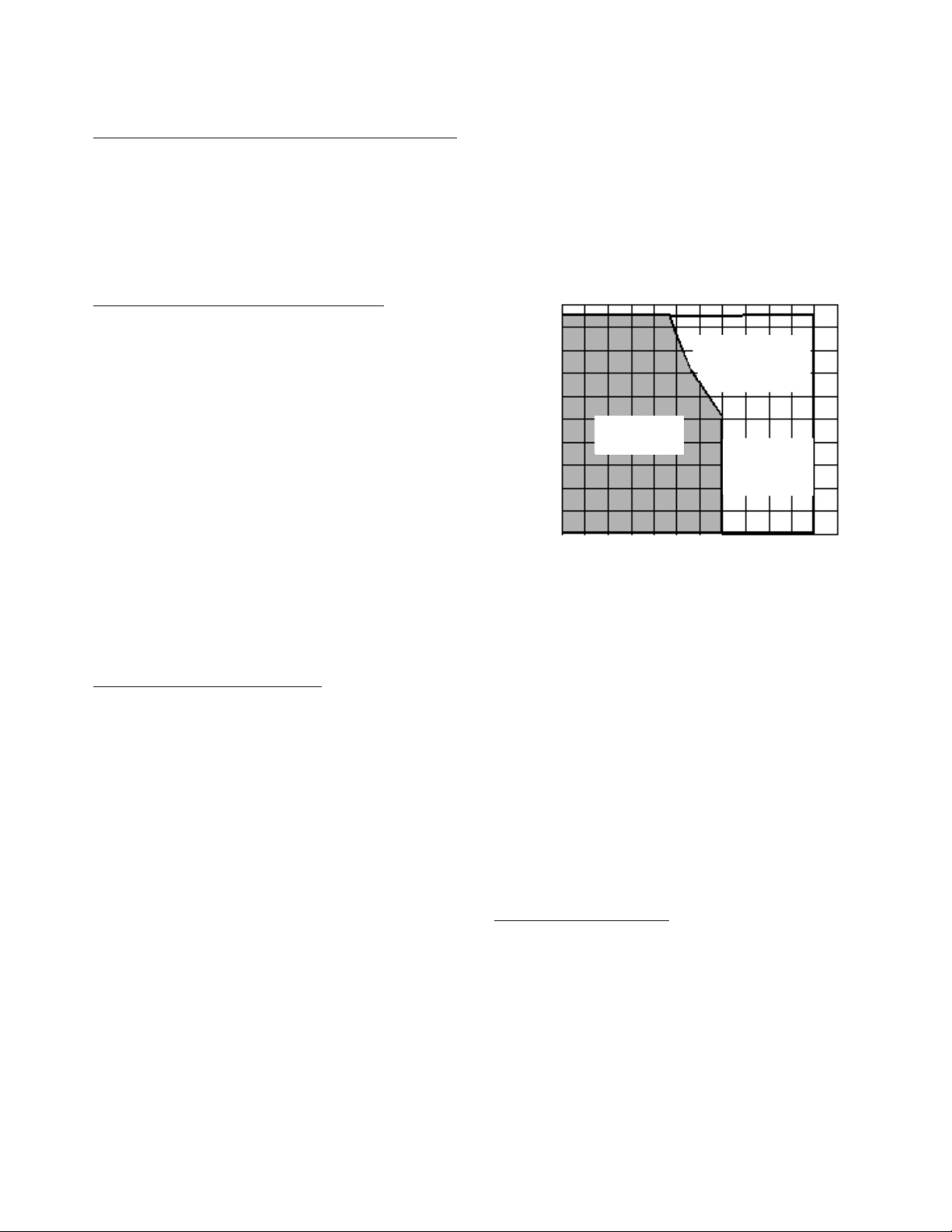
Measurement Accuracy (Within five minutes of calibration
[user initiated] and within the 7.5% average power environmental
window)
RF IN/OUT: ±(0.75 dB ±1.9 nW)
Antenna: Typically, ±(0.75 dB ±0.5 pW)
CDPD Signal Generator
(CDPD module is optional)
Frequency Range: 824 MHz to 894 MHz
Frequency Accuracy: ±500 Hz, typically ±50 Hz
1.7 GHz ≤fc ≤2.0 GHz
± (12% ± 50 µW)
Typically ± 10%
± (7.5% ± 50 µW)
Typically ± 5%
fc ≤ 1000 MHz
± (10% ± 50 µW)
Typically ± 7%
0˚C 10˚C 20˚C 30˚C 40˚C 50˚C 60˚C
32˚F 50˚F 68˚F 86˚F 104˚F 122˚F 140˚F
Temperature
100%
80%
40%
20%
60%
Relative Humidity

3
Output
RF IN/OUT Connector
Level Range: –137 dBm to –40 dBm into 50 Ω
Level Accuracy: ±1.0 dB (level >–127 dBm); if CDPD
analyzer is also connected add ±0.1 dB.
Typically ±1.0 dB for levels below –127 dBm
Reverse Power: 100 W continuous, temperature <40 °C,
75 W continuous for temperatures <55 °C
DUPLEX OUT Connector
Level Range: –125 dBm to –10 dBm into 50 Ω
Level Accuracy: ±1.5 dB, typically ±1.0 dB for all levels.
If CDPD analyzer is also connected add ±0.1 dB.
Reverse Power: 200 mW max
Modulation Type: GMSK with BT=0.5
Modulation Accuracy: <5% error in modulation index
CDPD Analyzer
(CDPD Module is optional)
RF Frequency Range: 869 MHz to 894 MHz
Input Level Range
RF IN/OUT: 3.2 mW to 60 W (+5 dBm to 47.78 dBm)
ANT IN: 0.5 mW to 31.6 µW (–33 dBm to +15 dBm)
RF Power Measurement
Frequency Range: 30 MHz to 1 GHz, 1.7 to 2.0 GHz
Accuracy: Same as graph on page 4.
Measurement Range RF IN/OUT: To achieve the specified
accuracy when measuring power at the RF In/Out port, the
internal signal generator level must be 60 dB below the
measured power or less than –20 dBm at the Duplex port.
100 MHz < fc<2.0 GHz: 4 mW to 100 W continuous,
temperatures <40 °C, 75 W continuous, for temperatures
<55 °C
30 MHz < fc<100 MHz: 4 mW to 1 W continuous
Supplemental Characteristics
Resolution: Three digits (Example: resolution of 10 mW for
powers <10 W and >1 W)
Frequency Error Accuracy: ±1 Hz plus frequency reference
Modulation Index Accuracy: <0.1% error in modulation index
Adjacent Channel Power Measurement Floor: Typically
–45 dBc
Alternate and Second Alternate Channel Power Measurement
Noise Floor 4: Typically –60 dBc
Signal Generator Specifications
RF Frequency
Range: 400 kHz to 1000 MHz, and 1.7 GHz to 2.0 GHz
Accuracy and Stability: ±(0.065 Hz plus reference oscillator
accuracy)
Output
RF IN/OUT Connector
Level Range: –137 dBm to –40 dBm into 50 Ω
Level Accuracy: ±1.0 dB (level >–127 dBm);
if RF Analyzer is also connected add ±0.1 dB.
Typically ±1.0 dB for levels below –127 dBm
DUPLEX OUT Connector
Level Range: –125 dBm to +3 dBm into 50 Ω
Level Accuracy: ±1.5 dB, typically ±1.0 dB for all levels
Reverse Power: 200 mW max
SWR: <1.7:1
Supplemental Characteristics
Resolution: 0.1 dB
Spectral Purity
(For output levels of <–10 dBm at DUPLEX OUT or
<–40 dBm at RF IN/OUT)
Harmonics: <–25 dBc
Non-Harmonic Spurious (>5 kHz from carrier):
250 kHz ≤fc<249 MHz <–45 dBc
249 MHz ≤fc≤1000 MHz <–60 dBc
1700 MHz ≤fc≤2000 MHz <–55 dBc
Residual FM (rms, CCITT filter):
250 kHz ≤fc<249 MHz <7 Hz
249 MHz ≤fc<501 MHz <4 Hz
501 MHz ≤fc≤1000 MHz <7 Hz
1700 MHz ≤fc≤2000 MHz <14 Hz
Supplemental Characteristics
SSB Phase Noise (20 kHz offset):
fc<1 GHz <–116 dBc/Hz
1.7 GHz < fc<2.0 GHz <–90 dBc/Hz
FM
FM Deviation Maximum (for rates >25 Hz):
400 kHz <f
c
<249 MHz 100 kHz
249 MHz <f
c
<501 MHz 50 kHz
501 MHz <f
c
<1000 MHz 100 kHz
1.7 GHz <f
c
<2.0 GHz 100 kHz
[FM not specified for (fcminus FM dev) <400 kHz]
FM Rate (1 kHz reference):
Internal: dc to 25 kHz (1 dB BW )
External:
AC Coupled: 20 to 75 kHz (typically 3 dB BW)
DC Coupled: dc to 75 kHz (typically 3 dB BW)
 Loading...