

0.4 to 1000 MHz
1.4 to 2.0 GHz
• Cellular and PCS frequency coverage
• Analog and digital (IS-95B and
IS-2000 1XRTT) capabilities
• Built-in average power meter with
±7.5% accuracy
• Waveform quality r (rho), frequency
error, code domain power, timing,
and phase analysis
• Built-in AWGN source for calibrated
E
b/No
settings
• Dedicated, one-button user interface
keys
• Firmware upgradeable (via PCMCIA to
Flash Memory)
• Network equipment manufacturer (NEM)
base station specific automation
software increases measurement
repeatability and enhances
technician efficiency
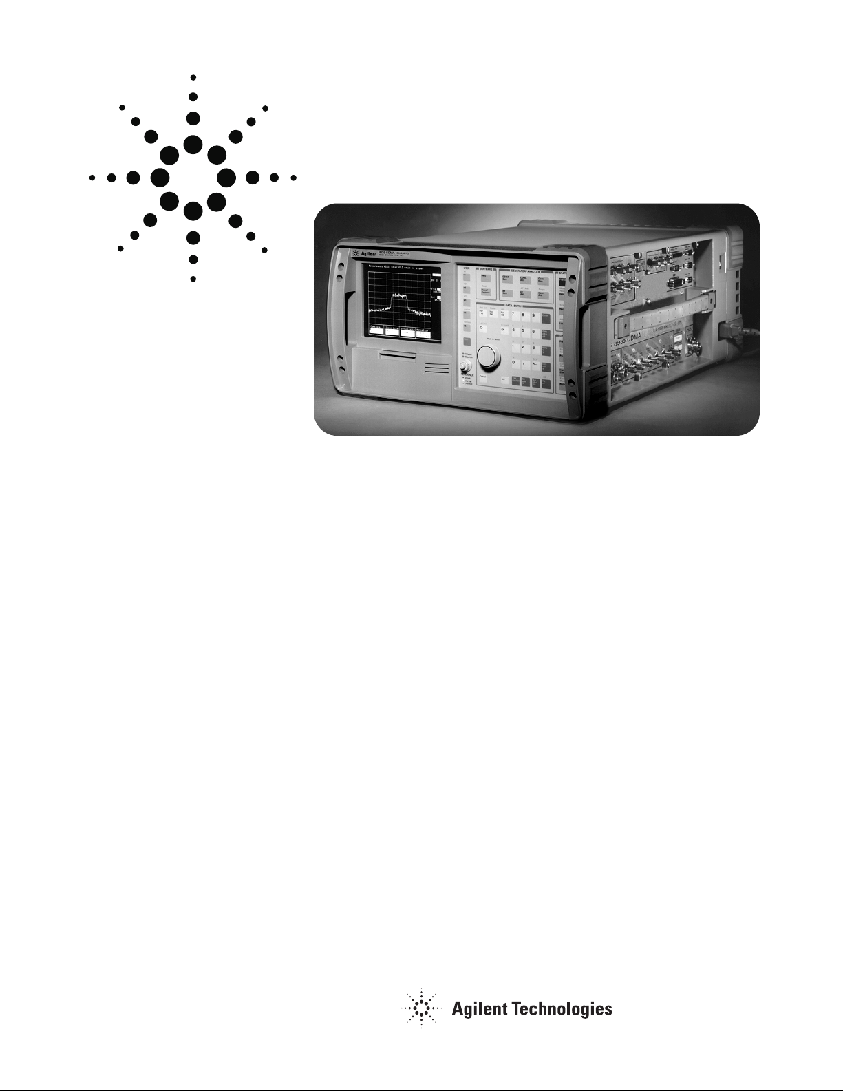
The Agilent Technologies 8935 Series
E6380A AMPS/CDMA Cellular/PCS
base station test set is the next generation in CDMA base station test
equipment. The E6380A is a full
featured, one-box test set designed
to meet the needs of installation
teams, service providers, and network
equipment manufacturers.
Building on the success of our third
generation of base station test
equipment, the new test set heavily
incorporates feedback from PCS and
Cellular users. For example, the
E6380A utilizes a large, bright, easy-toread, electroluminescent display. A
convenient connector section on the
side of the test set allows unobtrusive,
out-of-the-way hook up, as well as
protects the connectors from damage.
A suitcase form factor provides better
portability.
The new “rugged design” includes a
reliable membrane keypad, a gasketed
display, and filtered airf low to resist
dirt and moisture. The unit’s enclosure
provides for stand up operation, and
helps protect itself from bumps and
shocks.
More importantly, the E6380A incorporates a user-friendly interface with
one-key measurement execution. This
interface, coupled with test set’s fast
measurement speed and automated
software for LGIC, Lucent, Nortel,
and Samsung base stations, results
in less off-line time and improved
system performance. Errors due to
test variability are reduced, and
measurement data can be output to
a printer or to the PCMCIA memory
card. Additionally, new features and
capabilities can be added to the
E6380A without returning the unit
to a service center. The test set’s
firmware is user upgradeable via a
PCMCIA card to Flash Memory.
To complete the CDMA parametric test
solution, Agilent also offers a technician training program to provide
install teams and service providers
with a comprehensive understanding
of base station test.
For more information about the
8935 series E6380A, refer to the
products link on our Web site at:
www.agilent.com/find/basesta
tions
Agilent E6380A
8935 Series AMPS/CDMA
Base Station Test Set
Data Sheet
Specifications describe the instrument’s warranted performance and are
valid over the entire operating/environmental range unless otherwise noted.
Supplemental Characteristics are intended to provide additional information useful in applying the instrument by giving typical, but non-warranted
performance parameters. These characteristics are shown in italics or
labeled as “typical,” “usable to,” or “nominal.”
CDMA Signal Generator Specifications
Frequency Range: 800 MHz to 1000 MHz, and 1.7 GHz to 2.0 GHz
(usable 4 to 200 MHz)
Output Level Range:
RF IN/OUT: –120 dBm to –40 dBm
DUPLEX OUT: –120 dBm to –10 dBm
Output Level Accuracy:
RF IN/OUT: ±1.5 dB, Typically ±1 dB
DUPLEX OUT: ±1.5 dB, Typically ±1 dB
Modes: Noise only, data only, and user selectable E
b/No
settings
CDMA Signal Generator RF Level Accuracy
(when in E
b/No
mode): Typically ±1.5 dB
Modulation
Reverse Link Source Modulation: OQPSK per TIA IS-95
Reverse Link Source Modulation Data: Internal data buffer,
Idle (all zeroes)
Forward Link Source Modulation: QPSK per TIA IS-95
Forward Link Source Modulation Data: Internal (Pilot Channel)
Residual rho (r): Better than 0.96,
Typically better than 0.98
Carrier Feedthrough: Typically <–35 dBc
Adjacent Channel Noise: Typically <–50 dBc measured in a
30 kHz BW filter relative to the total carrier power at f
c
±900 kHz
for output levels <–40 dBm at the RF IN/OUT connector (<–10 dBm
when using the DUPLEX OUT connector)
Data Buffer
Size/Length: 1800 frames per data rate set
Modes: Single, Continuous Looping, and Idle
Coding: IS-95 CDMA full rate reverse link channel coding, inter-
leaving and spreading
Long Code Mask: 42 zeros
Input Data: 9600 bps and 14.4 kbps entered via GPIB
Data Source: For each data rate set there are 300 frames of random data factory loaded, 1800 frames additional user definable
data which can be entered via GPIB.
AWGN Source
(Additive White Gaussian Noise)
Bandwidth: 2 MHz nominally
Distribution: Gaussian to >3 sigma
E
b/No
Resolution: 0.1 dB
E
b/No
Range: –5 to 25 dB
E
b/No
Accuracy: ±0.5 dB for Eb/Noof 5 to 20 dB, 25° C ±10° C,
Typically ±1 dB for E
b/No
of 0 to +5 dB and +20 dB to +25 dB
CDMA Analyzer Specifications
Average Power Measurement
Input Frequency Range: 30 MHz to 1000 MHz, and 1.7 to 2.0 GHz
Input Connector: RF IN/OUT only
Measurement Bandwidth: Provides an accurate measure of the
total power for signals within ±2 MHz of the operating frequency.
If other signals are present outside this frequency range, reduced
measurement accuracy will result.
Maximum Input Level: 15 W average for CDMA signals
Measurement Range:
4 mW to 15 W for f >100 MHz (+6 to +42 dBm)
4 mW to 1 W for f <100 MHz (+6 to +30 dBm)
Measurement Period: 0.25 ms to 26.66 ms
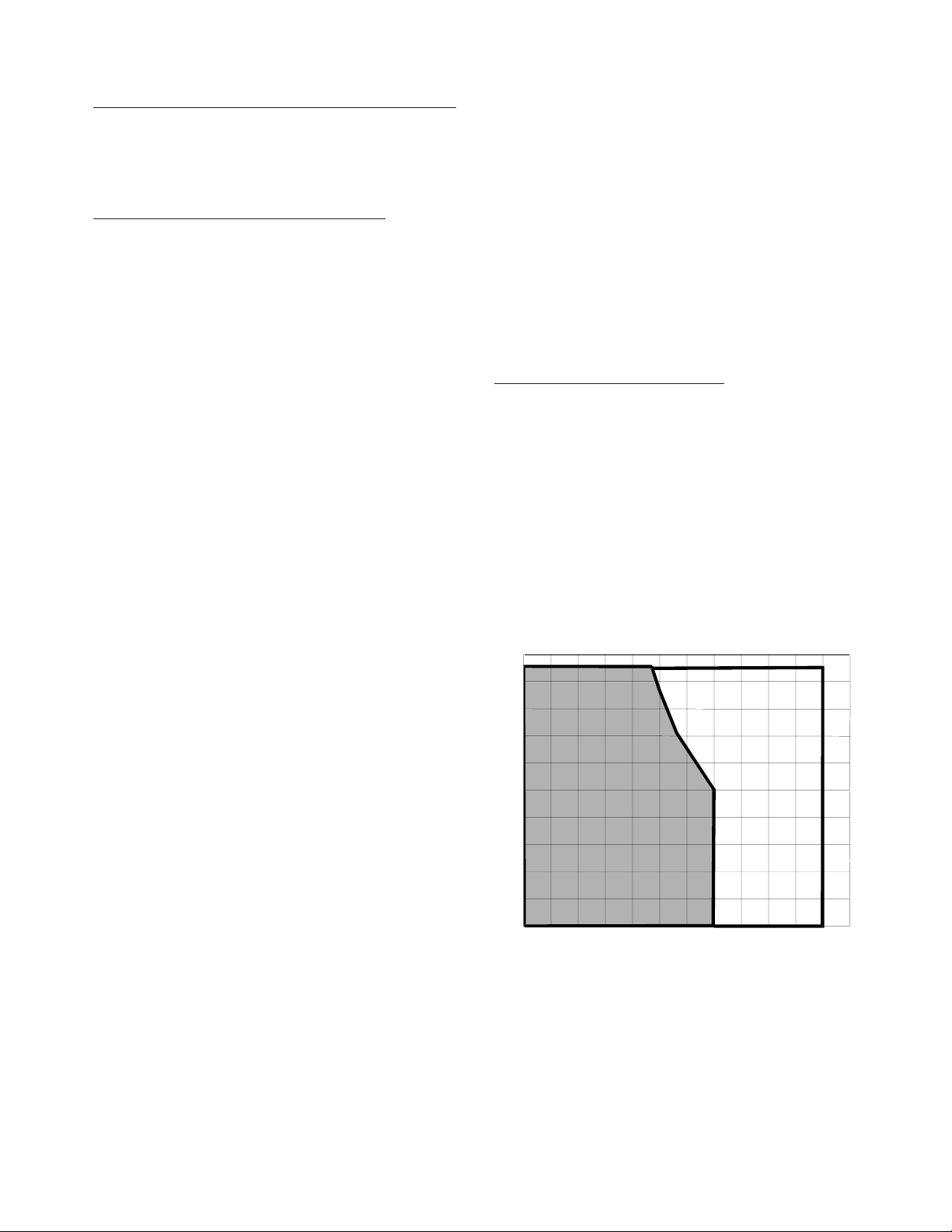
Figure 1. Average Power Measurement Accuracy
2
100%
80%
60%
40%
20%
0º C 10º C 20º C 30º C 40º C 50º C 60º C
32º F 50º F 68º F 86º F 104º F 122º F 140º F
Temperature
Relative Humidity
±(7.5% ±50 µW)
Typically ±5%
1.7 GHz≤f
c
≤2.0 GHz
±(12% ±50µW)
Typically 10%
f
c
≤1000 MHz
±(10% ±50 µW)
Typically ±7%

3
Channel Power Measurement (1.23 MHz)
Input Frequency Range: 800 MHz to 1000 MHz, and 1.7 to 2.0 GHz
Measurement Bandwidth: Measures the total average power in
a 1.23 MHz bandwidth centered on the selected frequency
Measurement Range:
RF IN/OUT: 0.1 µW to 15 W average (–40 to +42 dBm)
ANTENNA: Typically, 16 pW to 1.25 W average
(–78 to +4 dBm)
Measurement Accuracy (within five minutes of calibration (user
initiated) and within the 7.5% average power environmental window):
RF IN/OUT: 800 to 1000 MHz ± (0.75 dB ±25 nW)
at 4.95 MHz ± (1 dB ±40 nW)
ANTENNA: 800 to 1000 MHz typically, ± (0.75 dB ±6.5 pW)
at 4.95 MHz typically, ± (0.75 dB ±10 pW)
Measurement Period: 0.25 ms to 26.66 ms
Channel Power Measurement (30 kHz)
Input Frequency Range: 30 MHz to 1000 MHz, and 1.7 to 2.0 GHz
Measurement Bandwidth: Measures the total average power in
a 30 kHz bandwidth centered on the selected frequency
Measurement Range:
RF IN/OUT: 2.4 nW to 15 W average (–56 to +42 dBm)
ANTENNA: Typically, 0.39 pW to 1.25 W average
(–94 to +4 dBm)
Measurement Accuracy (within five minutes of calibration (user
initiated) and within the 7.5% average power environmental window):
RF IN/OUT: 30 to 1000 µHz ± (0.75 dB ±0.61 nW)
at 4.95 MHz ± (1 dB ±0.61 nW)
ANTENNA: At 4.95 MHz, 30 to 1000 MHz typically,
±(0.75 dB ±0.16 pW)
Measurement Period: 0.25 ms to 26.66 ms
Adjacent Channel Power
Frequency Range: 800 MHz to 1000 MHz and 1.7 GHz to 2.0 GHz
Adjacent Channel Power Bandwidth: 10 kHz to 1.23 MHz
(for BW >100 kHz, refer to ACP Filter in Reference Guide)
Adjacent Channel Power Offset: 100 kHz to 3 MHz
Measurement Range:
RF IN/OUT: 0.1 µW to 15 W average (–40 to +42 dBm)
ANTENNA: Typically 16 pW to 1.25 W average
(–78 to +4 dBm)
Measurement Accuracy:
RF IN/OUT:
Typically ±(0.75 dBc ±(2 x 10
–14
)(ACP BW)) W
ANTENNA
Typically ±(0.75 dBc ±(5.3 x 10
–18
)(ACP BW)) W
Waveform Quality Measurement
Frequency Range: 4 MHz to 1000 MHz, and 1.7 to 2.0 GHz
Input Level Range:
RF IN/OUT: –20 dBm to +42 dBm
ANTENNA: –58 dBm to +7 dBm
Measurement Period: 0.25 ms to 20 ms forward link 0.25 ms
to 10 ms reverse link
Measurement Range: 0.509 to 1.00
Rho Measurement Accuracy: Within ±0.005
Input Frequency Error Range: ±900 Hz
Frequency Error Measurement Accuracy: ±30 Hz using a
measurement interval >0.5 ms
Other Reported Parameters: Pilot Time Offset, Carrier Feedthrough
Error, Vector Magnitude, Amplitude Error, and Phase Error
Pilot Time Offset Measurement Accuracy: Typically <±500 nsec
from even second signal to start of PN sequence
Code Domain Analyzer
Frequency Range: 4 MHz to 1000 MHz, and 1.7 to 2.0 GHz
Input Connector: RF IN/OUT or ANT IN
Input Frequency Error Range: ±900 Hz
Input Level Range:
RF IN/OUT: –20 dBm to +42 dBm
ANTENNA: –58 dBm to +7 dBm
Code Domain Power Measurement
Displayed Dynamic Range: 40 dB
Relative Code Domain Power Accuracy: ±0.5 dB
(using a measurement interval >0.5 ms and Walsh channel power
>1% of channel power)
Absolute Code Domain Power Accuracy: ±1.25 dB
(using a measurement interval >0.5 ms and Walsh channel power
>1% of channel power)
Measurement Resolution: 0.01 dB
Carrier Frequency Offset Accuracy: ±30 Hz using a measurement
interval ≥0.5 ms
Pilot Time Offset Accuracy: Typically <500 nsec from even second signal to start of PN sequence
Other Reported Parameters: Estimated Rho, marker readings of
individual code power and noise
Code Domain Timing Measurement
1
(Pilot to Code Channel Time Tolerance)
Measurement Range: ±200 nsec
Measurement Accuracy: ±10 nsec using a measurement interval
of 12.5 ms
Measurement Resolution: 0.01 nsec
Code Domain Phase Measurement
1
(Pilot to Code Channel Phase Tolerance)
Measurement Range: ±200 mrad
1
IS-95B only
 Loading...