


HP E5574A
Optical Loss Analyzer
User’s Guide

Notices
This document contains proprietary information that is protected
by copyright. All rights are
reserved.
No part of this document may be
photocopied, reproduced, or
translated to another language
without the prior written consent
of Hewlett-Packard GmbH.
Copyright 1996 by:
Hewlett-Packard GmbH
Herrenberger Str. 130
71034 Böblingen
Federal Republic of Germany
Subject Matter
The information in this document is subject to change without notice.
Hewlett-Packard makes no warranty of any kind with regard to
this printed material, including,
but not limited to, the implied
warranties of merchantability
and fitness for a particular purpose.
Hewlett-Packard shall not be liable for errors contained herein or
for incidental or consequential
damages in connection with the
furnishing, performance, or use
of this material.
Printing History
New editions are complete revisions of the guide reflecting
alterations in the functionality of
the instrument. Updates are
occasionally made to the guide
between editions. The date on
the title page changes when an
updated guide is published. To
find out the current revision of
the guide, or to purchase an
updated guide, contact your
Hewlett-Packard representative.
Control Serial Number: First
Edition applies directly to all
instruments.
Warranty
ThisHewlett-Packardinstrument
product is warranted against
defects in material and workmanship for a period of one year
from date of shipment. During
the warranty period, HP will, at
its option,eitherrepairorreplace
products that prove to be defective.
For warranty service or repair,
this product must be returned to
a service facility designated by
HP. Buyer shall prepay shipping
charges to HP and HP shall pay
shipping charges to return the
product to Buyer. However,
Buyer shall pay all shipping
charges, duties, and taxes for
products returned to HP from
another country.
HP warrants that its software and
firmware designated by HP for
use with an instrument will execute its programming instructions when properly installed on
that instrument. HP does not
warrant that the operation of the
instrument, software, or
firmwarewill be uninterrupted or
error free.
Limitation of Warranty
The foregoing warranty shall not
apply to defects resulting from
improper or inadequate maintenance by Buyer, Buyer-supplied
software or interfacing, unauthorized modification or misuse,
operation outside of the environmental specifications for the
product, or improper site preparation or maintenance.
No other warranty is expressed
or implied. Hewlett-Packard specifically disclaims the implied
warranties of Merchantability
and Fitness for a Particular Purpose.
Exclusive Remedies
The remedies provided herein
are Buyer’s sole and exclusive
remedies. Hewlett-Packard shall
not be liable for any direct, indirect, special, incidental, or consequential damages whether
based on contract, tort, or any
other legal theory.
Assistance
Productmaintenance agreements
and other customer assistance
agreements are available for
Hewlett-Packard products. For
any assistance contact your nearest Hewlett-Packard Sales and
Service Office.
Certification
Hewlett-Packard Company certifies that this product met its published specifications at the time
of shipment from the factory.
Hewlett-Packard further certifies
that its calibration measurements
are traceable to the United States
National Institute of Standards
and Technology, NIST (formerly the United States National
Bureau of Standards, NBS) to
the extent allowed by the Institutes’s calibration facility,and to
the calibration facilities of other
International Standards Organization members.
ISO 9001 Certification
Produced to ISO 9001 international quality system standard as
part of our objective of continually increasing customer satisfaction through improved
process control.
Third Edition
September 1999
E5574-91011
E0999
(First Edition E0895)
(Second Edition E1096)
Hewlett-Packard GmbH
Herrenberger Str. 130
71034 Böblingen
Federal Republic of Germany

HP E5574A Optical Loss Analyzer
User’s Guide

Safety Summary
The following general safety precautions must be observed during
all phases of operation, service, and repair of this instrument.
Failure to comply with these precautions or with specific warnings
elsewhere in this manual violates safety standards of design,
manufacture, and intended use of the instrument. Hewlett-Packard
Company assumes no liability for the customer’s failure to comply
with these requirements.
General This is a Safety Class 1 instrument (provided with
terminal for protective earthing) and has been manufactured and
tested according to international safety standards.
Operation – Before applying power Comply with the
installation section. Additionally, the following shall be observed:
• Do not remove instrument covers when operating.
• Before the instrument is switched on, all protective earth
terminals, extension cords, auto-transformers and devices
connected to it should be connected to a protective earth via a
ground socket. Any interruption of the protective earth
grounding will cause a potential shock hazard that could result
in serious personal injury.
• Whenever it is likely that the protection has been impaired, the
instrument must be made inoperative and be secured against any
unintended operation.
• Make sure that only fuses with the required rated currentand of
the specified type (normal blow, time delay, etc.) are used for
replacement. The use of repaired fuses and the short-circuiting
of fuseholders must be avoided.
• Adjustments described in the manual are performed with power
supplied to the instrument while protective covers are removed.
Be aware that energy at many points may, if contacted,result in
personal injury.
• Any adjustments, maintenance, and repair of the opened
instrument under voltageshould be avoidedas much as possible,
and when unavoidable, should be carried out only by a skilled
person who is aware of the hazard involved. Do not attempt
internal service or adjustment unless another person, capable of
rendering first aid and resuscitation is present. Do not replace
components with power cable connected.
4

Safety Summary
• Do not operate the instrument in the presence of flammable
gases or fumes. Operation of any electrical instrument in such an
environment constitutes a definite safety hazard.
• Do not install substitute parts or perform any unauthorized
modification to the instrument.
• Be aware that capacitors inside the instrument may still be
charged even if the instrument has been disconnected from its
source of supply.
Safety Symbols
The apparatus will be marked with this symbol when it is necessary
for the user to refer to the instruction manual in order to protect the
apparatus against damage.
Caution, risk of electric shock.
Frame or chassis terminal.
Protective conductor terminal.
Hazardous laser radiation.
Electromagnetic interference (EMI)
WARNING The WARNINGsign denotes a hazard. It calls attention to a procedure,
practice or the like, which, if not correctly performed or adhered to,
could result in injury or loss of life. Do not proceed beyond a
WARNING sign until the indicated conditions are fully understood and
met.
CAUTION The CAUTION sign denotes a hazard. It calls attention to an operating
procedure, practice or the like, which, if not correctly performed or adhered
to, could result in damage to or destruction of part or all of the equipment.
Do not proceed beyond a CAUTIONsign until the indicated conditions are
fully understood and met.
5
Safety Summary
Initial Safety Information for Laser Source
The specifications for the laser source are as follows:
E5574A
Laser Type FP-Laser
InGaAsP
Laser Class
According to IEC 825 (Europe) 3A
According to 21 CFR 1040.10
(Canada, Japan, USA)
Output Power (CW) less than 500 µW
Beam Waist Diameter 9 µm
Numerical Aperture 0.1
Wavelength 1310 ±20nm
1550 ±20nm
1
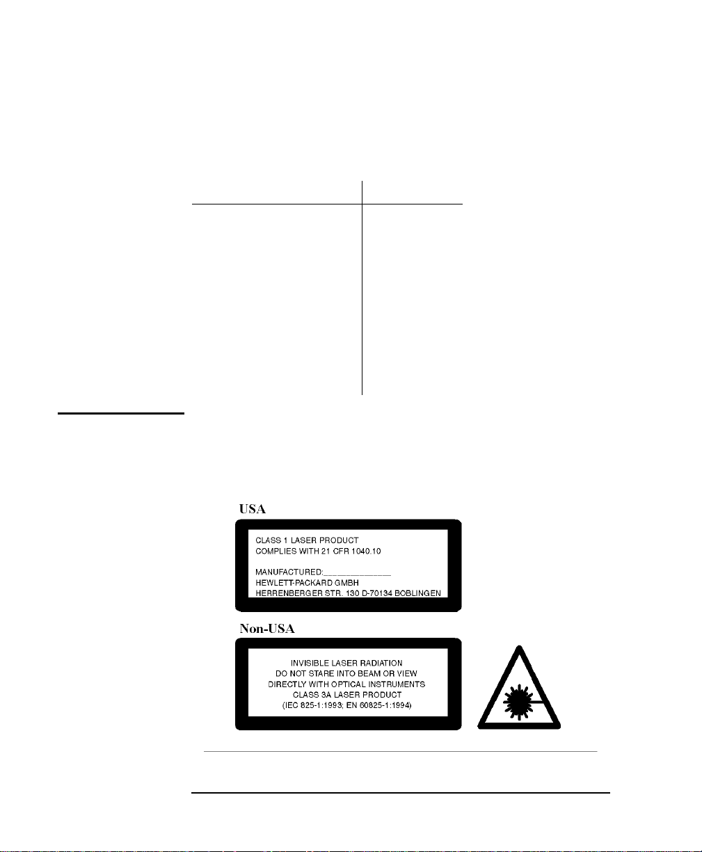
NOTE The laser safety warning labels are fixed on the front panel of the instrument.
6
Safety Summary
A sheet of laser safety warning labels is included with the laser module. You
muststick the labels in thelocal language onto the outside of the instrument,
in a position where they are clearly visible to anyone using the instrument.
NOTE The Max. Output Power stated on the label located on the rear panel of the
instrument are the maximum allowances for class 1 (USA) and class 3A
(non-USA) laser products respectively.
The real output power of the built-in laser source(s) never exceeds 500 µW.
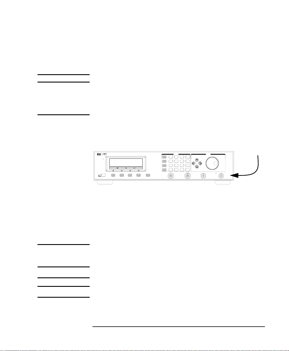
The recommended position for the laser safety warning label is the
bottom right corner on the front of the instrument as shown by the
arrow in the diagram below.
E5574A
OPTICAL LOSS ANALYZER
Appl 7
8
9
Instr
Source
On/Off
Syst
More
Head Input A Head Input B Optical Input Optical Output
Preset Cursor/Vernier
Aux
4
5
6
Help
1
2
3
Enter
0
•
+/–
MODIFYENTRY
Active
You must return instruments with malfunctioning laser modules to
a HP Service Center for repair and calibration, or have the repair
and calibration performed on-site by HP personnel.
The laser module has built in safety circuitry that disables the
optical output in the case of a fault condition.
WARNING Use of controls or adjustments or performance of procedures other
than those specified for the laser source may result in hazardous
radiation exposure.
WARNING Refer Servicing only to qualified and authorized personnel.
WARNING Do not enable the laser when there is no fiber attached to the optical
output connector.
The optical output connector is at the bottom right corner of the
7

Safety Summary
instrument’s front panel.
The laser is enabled bypressing SOURCE ON/OFF. The laser is enabled
when the green LED on the front panel of the laser module is lit.
WARNING Under no circumstances look into the end of an optical cable attached
to the optical output when the device is operational.
The laser radiation is not visible to the humaneye, but it canseriously
damage your eyesight.
There is a safety circuit which monitors the average laser power
output, and the power output of each laser pulse. If either the
average or the pulse power is greater than the limit for the module,
the laser will be disabled.
8


In This Book
The Structure of this Manual
This manual is divided into four parts:
• General information and guidelines in chapter 1.
• The operating guide, describing how to use the instrument from
the front panel, in chapters 2 to 7.
• The programming guide, describing how to operate the
instrument remotely via the HP-IB, in chapter 8.
• Additional information not required for routinely day-to-day use
in the appendix.
Conventions used in this Manual
• Quoted terms like “Pol. Depend. Loss” are menu items or
applications, respectively.
• Small capitals are used to indicate front panel keys, e.g. PRESET.
• Grey text is used to indicate softkeys, e.g. SELECT.
10

Contents
1 Introducing the HP E5574A Optical Loss Analyzer
1.1 The Components of the OLA 23
1.2 What You Can Do With the OLA 24
Operational Modes 24
The OLA Applications 25
1.3 The OLA Front Panel Keys 26
The Softkeys 27
The MORE Key 27
The Keypad 27
The Cursor Control Keys 28
The Rotary Knob 29
1.4 Operating the OLA 29
1.5 Help is Available 30
1.6 Getting Started 31
Power-On 31
General Instrument Settings 32
Zeroing the Heads 33
Storing the Reference Power 34
Checking the Stability 36
1.7 How to Obtain Exact Results 37
Mechanical Stability 37
Selection of the Optical Heads 37
The Influence of the Output Connector 38
2 Taking Polarization Dependent Measurements
2.1 Measuring Polarization Dependent Loss 41
PDL Measurement Setup 41
11

Contents
Starting the Measurement 42
Checking the Measurement Conditions 43
Checking the Stability of the Setup 43
Repeating the PDL Measurement 43
Measuring PDL and Insertion Loss Simultaneously 44
Explanation of the Results 44
2.2 Measuring the Polarization Dependent Characteristics
of Couplers 46
PD Coupler Test Measurement Setup 46
Starting the Measurement 47
Checking the Measurement Conditions 48
Checking the Stability of the Setup 48
Continuing the Measurement 49
Repeating the Measurement 49
Explanation of the Results 50
3 Taking Standard Loss Measurements
3.1 Measuring the Insertion Loss 55
Insertion Loss Measurement Setup 56
Starting the Measurement 57
Checking the Measurement Conditions 57
Checking the Stability of the Setup 58
Explanation of the Result 58
3.2 Measuring the Return Loss 58
Return Loss Calibration Setup 59
Calibrating for RL Measurements 60
Return Loss Measurement Setup 62
Starting the Measurement 63
Checking the Stability of the Setup 63
Checking the Influence of Polarization 63
12

Contents
Explanation of the Result 64
4 Testing Optical Couplers
4.1 Measuring Optical Coupler Characteristics 67
Coupler Test Measurement Setup 67
Starting the Measurement 68
Checking the Measurement Conditions 69
Checking the Stability of the Setup 69
Continuing the Coupler Test 70
Measuring the Directivity 71
Explanation of the Results 72
5 Measuring Power
5.1 Measuring Absolute and Relative Power 75
Powermeter Measurement Setup 75
Starting the Measurement 76
Checking the Measurement Conditions 76
Storing a Reference Value 77
Setting the Measurement Mode 78
Measuring the Fluctuation of Optical Power 79
Explanation of the Results 80
6 Using the OLA as a Laser Source and Polarization
Controller
6.1 Using the OLA as a Laser Source 83
Using the Internal Laser 83
Using an External Source 84
6.2 Using the OLA as a Polarization Controller 84
13

Contents
Sweeping Through all States of Polarization 85
Setting a Reproducible State of Polarization 87
7 Instrument Settings and Software Status
7.1 Checking the General Instrument Settings 91
7.2 Checking the System Configuration 91
7.3 Checking the Software Status 92
8 HP-IB Programming
8.1 Introduction to Programming the OLA 95
The HP Interface Bus 95
Setting the HP-IB Address 96
Modes of Operation 96
OLA Specific Features 97
How the OLA Processes HP-IB commands 98
Some Notes about Programming and Syntax Conventions 99
8.2 Command Summary 101
IEEE Common Commands 101
SCPI Standard STATUS Commands 102
OLA Specific Commands 103
8.3 IEEE Common Commands 107
General Remarks 108
Command Descriptions 109
8.4 Standard STATUS Commands 118
General Remarks 118
Command Descriptions 120
8.5 OLA Specific Commands 125
14

Contents
8.6 Programming Examples 159
Example 1 - Checking the Communication 159
Example 2 - Reading Power and Storing the Reference 160
A Installation and Maintenance
Safety Considerations 165
Initial Inspection 165
AC Line Power Supply Requirements 166
Line Power Cable 166
Replacing the Fuse 168
Replacing the Battery 169
Environmental Specifications 170
Instrument Positioning and Cooling 171
Optical Output 171
HP-IB Interface 172
Connector 172
HP-IB Logic Levels 173
Claims and Repackaging 174
Return Shipments to HP 174
B Accessories
Instrument and Options 177
HP-IB Cables and Adapters 178
Connector Interfaces and Other Accessories 179
C Specifications
15

Contents
Definitions of Terms 185
Technical Data, Product Specifications and Characteris-
tics 188
D Performance Test
Required Test Equipment 195
General 196
Setup and Performing the Performance Test 196
Setting the Wavelength 197
Test I. Center Wavelength 198
Test II. Output Power 199
Test III. CW-Stability Short Term 200
Test IV. Linearity and Accuracy 202
Test V. PDL/PDG uncertainty (#020 only) 206
Test VI. Repeatability PDL/PDG 208
Test VII. Noise 210
Absolute PDCR Uncertainty, Repeatability for PDCR 212
Performance Test Form Sheets 213
E Cleaning Procedure
The Cleaning Kit 223
Other Cleaning Tools 225
Preserving Connectors 227
Cleaning Instrument Housings 228
16

Contents
Cleaning Procedures 228
Cleaning Cable Connectors 228
Cleaning Connector Adapters 230
Cleaning Connector Interfaces 231
Cleaning Bare Fiber Adapters 232
Cleaning Bare Fiber Ends 233
Cleaning Lenses 233
Cleaning Large Area Lenses and Mirrors 234
Cleaning Fixed Connector Interfaces 235
Cleaning Optical Glass Plates 236
Cleaning Physical Contact Interfaces 236
Cleaning Recessed Lens Interfaces 237
Cleaning Fragile Optical Devices 238
Cleaning Metal Filters or Attenuator Gratings 239
F Error Messages
Display Messages 243
Light A?, Light B?, Light A & B? 243
No Head A, No Head B, No Heads 243
P < P par ? 243
HP-IB Messages 244
Instrument Specific Errors 244
Command Errors (-100 to -199) 244
Execution Errors (-200 to -299) 248
Device-Specific Errors (-300 to -399) 249
Query Errors (-400 to -499) 250
17

Figures
1-1 The OLA Components 23
1-2 The OLA Front Panel 26
1-3 Select Application Display 27
1-4 Example of an Application Display 29
1-5 Preset Display 32
1-6 Setup for Measuring the Reference Power 35
2-1 Setup for PDL Measurements 41
2-2 Polarization Dependent Loss Display 42
2-3 Polarization Dependent Loss / Insertion Loss Display 44
2-4 Setup for PD Coupler Test 46
2-5 Polarization Dependent Coupler Test Display, Page 1 47
2-6 Polarisation Dependent Coupler Test Display, Page 2 49
2-7 Connection Scheme for Optical Couplers 50
3-1 Setup for Insertion Loss Measurements 56
3-2 Insertion Loss Display 57
3-3 Setup for Return Loss Calibration 59
3-4 Return Loss Settings Display 60
3-5 Return Loss Calibration Display 61
3-6 Setup for Return Loss Measurements 62
3-7 Return Loss Display 63
4-1 Setup for Coupler Test 67
4-2 Coupler Test Display, Page 1 68
4-3 Coupler Test Display, Page 2 70
4-4 Coupler Test Directivity Display 71
4-5 Connection Scheme for Optical Couplers 72
5-1 Powermeter Setup 75
5-2 Powermeter Display 76
5-3 Powermeter Settings Display 76
5-4 Powermeter Minimum/Maximum Display 79
6-1 Polarization Controller Rate Settings Display 86
6-2 Polarization Controller Paddle Settings Display 87
7-1 System Configuration Display 91
8-1 Common Status Registers 108
A-1 Line Power Cables – Plug Identification 166
A-2 Rear Panel Markings 168
18

Figures
A-3 Releasing the Fuse Holder 168
A-4 The Fuse Holder 169
A-5 Correct Positioning of the HP E5574A 171
A-6 The HP-IB Connector 172
D-1 Center Wavelength Test Setup 198
D-2 Output Power Test Setup 199
D-3 CW-Stability Short Term Test Setup 200
D-4 Accuracy Test Setup 202
D-5 Linearity Test Setup 204
D-6 PDL/PDG Uncertainty Test Setup 206
D-7 Example Drawings 207
D-8 Repeatability PDL/PDG Test Setup 208
D-9 Noise Test Setup 210
19

Tables
8-1 HP-IB Capabilities 96
8-2 EEE Common Commands 101
8-3 SCPI Standard STATUS Commands 102
8-4 Application Independent Commands 103
8-5 PDCT Specific Commands 103
8-6 IL Specific Commands 104
8-7 PDL/IL Specific Commands 104
8-8 Coupler Test Specific Commands 104
8-9 Return Loss Specific Commands 105
8-10 Powermeter Specific Commands 106
8-11 Min/Max Application Specific Commands 107
8-12 Commands, which are Called from all Applications 107
20

1
1 Introducing the HP E5574A
Optical Loss Analyzer

Introducing the
HP E5574A
Optical Loss Analyzer
In this chapter you will find basic information about the HP
E5574A Optical Loss Analyzer (OLA).
After reading this chapter you will know
• how the instrument works,
• which applications it supports,
• how it is operated.
22

Introducing the HP E5574A Optical Loss Analyzer
m
r
o
o
1
The Components of the OLA
1.1 The Components of the OLA
The HP E5574A Optical Loss Analyzer is a complete solution for
the loss/gain characterization of active and passive optical
components. The instrument has been optimized to measure the
loss of optical fibers and components caused by different states of
polarization.
Signal Processing and Display
Head Input AHead Input A Head Input BHead Input B Optical Input Optical OutputHead Input A Head Input B Optical Input Optical Output
Figure 1-1 The OLA Components
Choice of
• 1310 nm
• 1550 nm
• 1310 & 1550 n
Fabry-Perot Lase
Internal
Source(s)
Choice of
• 81525A
• 81524A
• 81521B opt 00
Detector Heads
Choice of
• Bare Fiber Pigtail
• Straight Contact Connect
• Angled Contact Connect
Coupler
Pol. Ctrl.
3 dB
• Tunable Laser Sourc
or
• White Light Source
or
• LED
23

Introducing the HP E5574A Optical Loss Analyzer
What You Can Do With the OLA
The OLA consists of
• one or two built-in Fabry-Perot laser sources,
• a 3-dB optical coupler for the connection of an external source
and for Return Loss measurements,
• a4-paddle polarization controller for automaticsweep or manual
setting of the polarization,
• an optical output with either a FC/PC terminated fiber pigtail, or
a straight contact connector, or an angled contact connector,
• one or two optical heads, chosen to match wavelength and
sensitivity requirements,
• the signal processing and display unit.
1.2 What You Can Do With the OLA
As one can see from Figure 1-1, the OLA has one output and three
input ports. It therefore supports a variety of applications.
Operational Modes
You can set-up the OLA to perform as follows:
• It can serve as a highly stable source of linear polarized infra-red
light with a wavelength of 1310 nm and/or 1550 nm.
• It can launch its own or any light from anexternal source to any
optical device under test (DUT).
• It can circulate the optical output through all states of
polarization or establish any desired state of polarization.
• Once the source power has been measured and stored, you can
measure the Insertion Loss of any passive DUT, the output of
which is connected to one of the optical heads.
24

Introducing the HP E5574A Optical Loss Analyzer
What You Can Do With the OLA
• You can measure the optical power of any active optical device
connected to one of the optical heads.
• You can measure two optical powers simultaneously (which is
mandatory for comparing active or passive optical devices and
for measuring optical couplers).
• You can measure the polarization dependent characteristics of
the DUT, be that two-port devices or couplers.
• By connecting the sensor head to the optical input, you can
measure the backreflection of a DUT, called Return Loss.
The OLA Applications
The OLA applications include the following measurements:
Insertion Loss (IL)
You measure the power loss of passive optical components.
Polarization Dependent Loss (PDL)
You measure the maximal power fluctuation caused by the DUT’s
sensitivity to changes in polarization.
Coupler Test
You measure the Coupling Ratio (CR), Splitting Ratio (SR),
Insertion Loss (IL), Excess Loss (EL), and Directivity (DIR) of
optical couplers.
Polarization Dependent Coupler Test
You measure the Polarization Dependent Coupling Ratio (PDCR),
Splitting Ratio (PDSR), Loss (PDL), and Excess Loss (PDEL) of
optical couplers.
PDL / Insertion Loss
You measure the Polarization Dependent Loss (PDL) and the
averaged Insertion Loss (IL avg) simultaneously.
25

Introducing the HP E5574A Optical Loss Analyzer
The OLA Front Panel Keys
Return Loss (RL)
You measure the fraction of power which is scattered back to the
source by a component.
Powermeter
You measure the absolute or relative power of one or two light
sources in dBm or Watts.
1.3 The OLA Front Panel Keys
This paragraph deals with the operation of the OLA using the front
panel keys and the rotary knob.
Press APPL to choose the application
E5574A
OPTICAL LOSS ANALYZER
More
Press MORE to access all options of each application “Source on” indicator
Figure 1-2 The OLA Front Panel
The OLA can also be
operated remotely,
controlled by a computer
using the HP Interface
The front panel shows (from left to right) the power on/off key,four
keys below the display, the MORE key, a numerical keypad with
additional function keys, four cursor control keys, and the rotary
knob.
Bus. See Chapter 8 “HPIB Programming” for
details.
26
Appl 7
Instr
Source
On/Off
Syst
8
9
Preset Cursor/Vernier
4
5
1
2
0
•
Head Input A Head Input B Optical Input Optical Output
Aux
6
Help
3
Enter
+/–
MODIFYENTRY
Active
Introducing the HP E5574A Optical Loss Analyzer
The OLA Front Panel Keys
The Softkeys
The four keys below the display are softkeys (software controlled
keys). Their meaning changes according to the instrument
application you use.
The current function of each softkey is indicated in the
corresponding box on the display.
The MORE Key
The key named MORE is used to activate and to display additional
softkeys. An application can thus provide more than four softkeys.
After selecting an application, always press MORE to view any
additional options provided by the application. Press MORE once
again to return to the first screen.
The Keypad
The keypad comprises numerical keys as well as named keys.
The numerical keys can be used to enter numerical parameters.
The named keys can be pressed at any time. They are used as
follows:
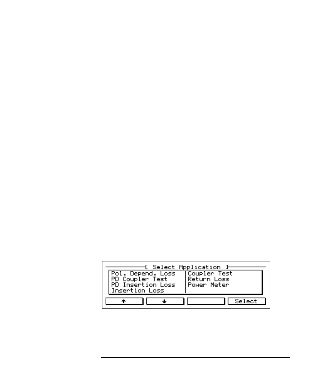
APPL Use this key to invoke the “Select Application” menu which
shows the list of applications.
Figure 1-3 Select Application Display
27

Introducing the HP E5574A Optical Loss Analyzer
The OLA Front Panel Keys
With the softkeys, the cursor control keys, or the rotary knob you
can choose any application. To start the highlighted application
press SELECT or ENTER or APPL once more.
If you have started an
application, you can
directly access all relevant
settings.
These settings apply to all
the measurements you
take.
INSTR Use this key to invoke the “Select Instrument” menu. You
can check or change the settings of the light source, the polarization
controller, and the powermeter.
SOURCE ON/OFF Use this key to turn the internal laser light
source on or off. The “Source on” indicator lamp shows the current
state.
SYST Use this key to invoke the “System Configuration” screen.
You can check and change the current HP-IB address of the
instrument.
PRESET Use this key to check and to change the general
instrument settings for the measurement sensitivity and for the
display of measured values.
ATTENTION Pressing this key does not reset the instrument to
power-up defaults!
AUX Use this key to display the status of the software presently
installed.
HELP Use this key to invoke the built-in help system.
ENTER Use this key to confirm the selection of a menu item or to
terminate the manual input of a numerical parameter value.
The Cursor Control Keys
The use of the cursor control keys depends on the application.
↑ / ↓ Use these keys to either move the cursor on the display or to
decrement/increment the highlighted parameter value.
→ / ← If the upper right-hand corner of the window frame on the
display shows > or <, you use these keys to proceed to a second
page or to return to the previous page.
28

Introducing the HP E5574A Optical Loss Analyzer
Operating the OLA
When changing a numerical parameter, you can use these keys to
move the cursor.
The Rotary Knob
The rotary knob performs like ↑ / ↓. It is especially useful if you
want to increment or decrement a highlighted parameter value
quickly and conveniently.
1.4 Operating the OLA
In general, the OLA is operated by means of the softkeys. Each
application comes with its own set of softkeys.
For example:
Figure 1-4 Example of an Application Display
The display shows not only the measured parameters and value(s),
but also the current measurement conditions, which can be changed
at the touch of a softkey.
If you want to measure the same parametersat head B or atanother
optical wavelength, simply press the corresponding softkey below
the screen.
However, there are some exceptions to the rule.
29

Introducing the HP E5574A Optical Loss Analyzer
Help is Available
Please note:
• The application may provide more options than are displayed.
Press MORE to view any additional softkeys available.
• The > in the upper right-hand corner of the window frame
indicates, that a second page exists. Press → to access this page.
Press ← to return.
• If you chose a numerical parameter to be changed (by pressing
the appropriate softkey), use the rotary knob, or ↑ / ↓, or the
numerical keypad to set its new value.
• The named keys take precedence over the softkeys. If youpress
one of these keys, the current application will be suspended.
ATTENTION The display does not show the general instrument
settings. These can only be accessed by pressing the PRESET key!
ATTENTION The display may burn in if itremains unchanged
for longer than 24 hours. To avoid damaging the display:
• Change the appearance of the display occasionally.
• Turn off the OLA when it is not in use.
1.5 Help is Available
Whenever you are in doubt, press HELP.
You will get information about the current screen. If you need more
information, press SEARCH.
You will then see an alphabetical list of related topics. This list
covers the parameters displayed and all related softkeys, including
those which are only availableafter pressing MORE. The list usually
comprises several pages.
From this list, you can access help to any parameter and/or softkey.
30
 Loading...