


Agilent Technologies
E5400-Pro Series Soft
Touch Connectorless
Probes
User’s Guide
A

Notices
© Agilent Technologies, Inc. 2004-2007
No p art o f this manu al may be re produce d in
any form or by any means (including electronic storage and retrieval or translation
into a foreign language) without prior agreement and written consent from Agilent
Technologies, Inc. as governed by United
States and international copyright laws.
Manual Part Number
E5404-97006, December 2007
Print History
E5404-97000, June 2004
E5404-97002, November 2004
E5404-97003, May 2005
E5404-97004, August 2005
E5404-97005, May 2006
E5404-97006, December 2007
Agilent Technologies, Inc.
1900 Garden of the Gods Road
Colorado Springs, CO 80907 USA
Warranty
The material contained in this document is provided “as is,” and is subject to being changed, without notice,
in future editions. Further, to the maximum extent permitted by applicable
law, Agilent disclaims all warranties,
either express or implied, with regard
to this manual and any information
contained herein, including but not
limited to the implied warranties of
merchantability and fitness for a particular purpose. Agilent shall not be
liable for errors or for incidental or
consequential damages in connection with the furnishing, use, or performance of this document or of any
information contained herein. Should
Agilent and the user have a separate
written agreement with warranty
terms covering the material in this
document that conflict with these
terms, the warranty terms in the separate agreement shall control.
Technology Licenses
The hardware and/or software described in
this document are furnished under a license
and may be used or copied only in accordance with the terms of such license.
Restricted Rights Legend
If software is for use in the performance of a
U.S. Government prime contract or subcontract, Software is delivered and licensed as
“Commercial computer software” as
defined in DFAR 252.227-7014 (June 1995),
or as a “commercial item” as defined in FAR
2.101(a) or as “Restricted computer software” as defined in FAR 52.227-19 (June
1987) or any equivalent agency regulation or
contract clause. Use, duplication or disclosure of Software is subject to Agilent Technologies’ standard commercial license
terms, and non-DOD Departments and
Agencies of the U.S. Government will
receive no greater than Restricted Rights as
defined in FAR 52.227-19(c)(1-2) (June
1987). U.S. Government users will receive
no greater than Limited Rights as defined in
FAR 52.227-14 (June 1987) or DFAR
252.227-7015 (b)(2) (November 1995), as
applicable in any technical data.
Safety Notices
CAUTION
A CAUTION notice denotes a hazard. It calls attention to an operating procedure, practice, or the like
that, if not correctly performed or
adhered to, could result in damage
to the product or loss of important
data. Do not proceed beyond a
CAUTION notice until the indicated
conditions are fully understood and
met.
WARNING
A WARNING notice denotes a
hazard. It calls attention to an
operating procedure, practice, or
the like that, if not correctly performed or adhered to, could result
in personal injury or death. Do not
proceed beyond a WARNING
notice until the indicated conditions are fully understood and
met.
2 E5400-Pro Series Soft Touch User’s Guide

Contents
1 Overview, Installation, and Selection of Probing Options
The E5400-Pro Series Soft Touch Probes — at a Glance 8
Installation Instructions 10
Selection of Probing Options 12
Retention Modules 13
The E5402A-Pro Series Low-profile Right-angle 34-channel
Single-ended Soft Touch Probe (for analyzers with 90-pin
cable connectors) 14
The E5404A-Pro Series 34-channel Single-ended Soft Touch
Probe
(for analyzers with 40-pin cable connectors) 15
The E5405A-Pro Series 17-channel Differential Soft Touch Probe
(for analyzers with 90-pin cable connectors) 16
The E5406A-Pro Series 34-channel Single-ended Soft Touch
Probe
(for analyzers with 90-pin cable connectors) 17
The E5386A Half-channel Adapter (for use with the 16760A logic
analyzer) 18
2 Mechanical Considerations
Characteristics 20
Probe Dimensions 21
Board Layout Dimensions 25
Retention Module Dimensions 25
Footprint Dimensions 27
Pin Outs for the Probes 28
Probing with E5404A-Pro Series Probe 29
E5400-Pro Series Soft Touch User’s Guide 3

Probing with the E5405A-Pro Series Probe 32
Probing with the E5402A/E5406A-Pro Series Probe 34
E5386A Half-channel Adapter Dimensions 36
Pin out for the E5386A half-channel adapter when connected to
E5405A 37
Pin out for two E5386A half-channel adapters connected to one
E5402A or E5406A 38
3 Operating the E5404A-Pro Series Probes
Equivalent Probe Loads 42
Time Domain Transmission (TDT) 44
4 Operating the E5402A, E5405A, and E5406A-Pro Series Probes
Equivalent Probe Loads 48
Time Domain Transmission (TDT) 50
Step Inputs 53
Eye Opening 56
5 Circuit Board Design
Transmission Line Considerations 60
Recommended Routing 61
Data and Clock Inputs per Operating Mode 63
Thresholds 66
E5404A-pro series single-ended soft touch probes 66
E5405A-pro series differential soft touch probe 66
E5402A and E5406A-pro series single-ended soft touch
probes 67
Signal Access 67
Labels split across probes 67
Reordered bits 67
4 E5400-Pro Series Soft Touch User’s Guide

Half-channel 1.25 and 1.5 Gb/s modes (16760A only) 68
6 Recommended Reading
For More Information 70
MECL System Design Handbook 70
High-speed Digital Design 70
Designing High-speed Target Systems for Logic Analyzer
Probing 70
E5400-Pro Series Soft Touch User’s Guide 5

6 E5400-Pro Series Soft Touch User’s Guide

Agilent E5400-Pro Series Soft Touch Connectorless Probes
User’s Guide
1
Overview, Installation, and Selection of
Probing Options
The E5400-Pro Series Soft Touch Probes — at a Glance 8
Installation Instructions 10
Selection of Probing Options 12
A
7
1 Overview, Installation, and Selection of Probing Options
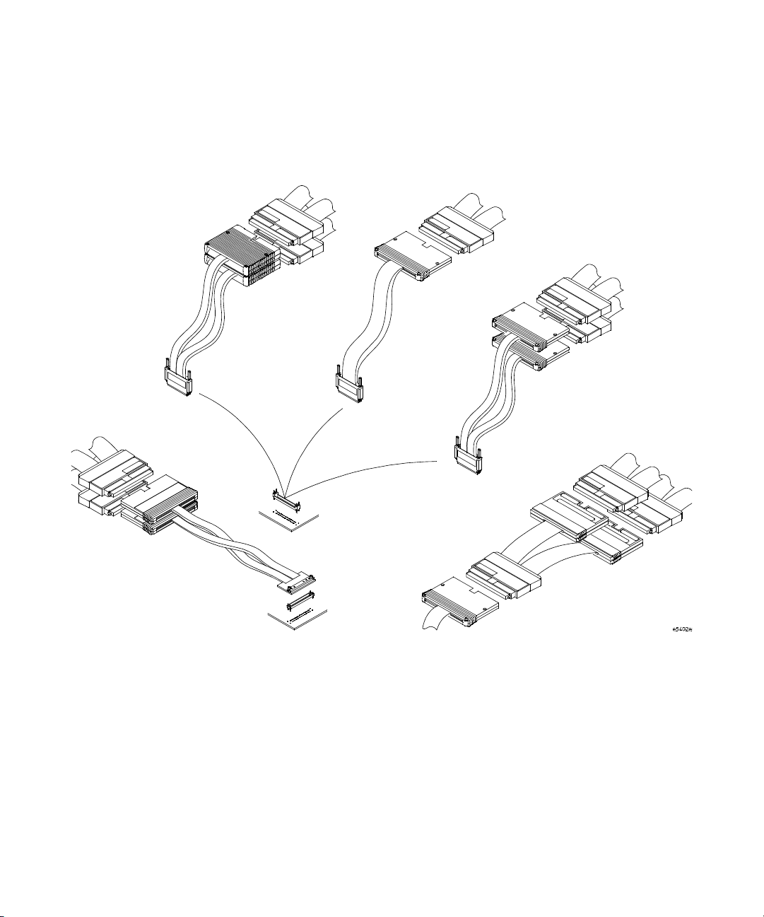
The E5400-Pro Series Soft Touch Probes — at a Glance
90-pin LA cables
E5402A-Pro
Series
Single-ended
E5412A right-angle
retention module
(34-chan)
E5404A-Pro
Series
Single-ended
40-pin LA cable
E5403A retention
module (34-chan)
E5402A,
E5405A &
E5406A-Pro
Series
90-pin LA cables
90-pin LA cables
E5405A-Pro
Series
Differential
E5406A-Pro
Series
Single-ended
16760A logic analyzer
E5386A
(used with 16760A logic
analyzer only)
8 E5400-Pro Series Soft Touch User’s Guide

Overview, Installation, and Selection of Probing Options 1
The new Agilent E5400-pro series soft touch probes are
ultra- low-load connector- less probes that work with the
Agilent logic analysis modules. The probes attach to the PC
board using a retention module which ensures pin- to- pad
alignment and holds the probe in place.
• The E5402A- pro series probe is a low-profile right- angle
34- channel single- ended connectorless soft touch probe
(for analyzers with 90-pin cable connectors).
• The E5404A- pro series probe is a 34-channel single- ended
connectorless soft touch probe (for analyzers with 40- pin
cable connectors).
• The E5405A- pro series probe is a 17-channel differential
connectorless soft touch probe (for analyzers with 90- pin
cable connectors).
• The E5406A- pro series probe is a 34-channel
single- ended connectorless soft touch probe (for analyzers
with 90- pin cable connectors).
Use the following information to design your target system
board for use with the Agilent soft touch probes.
E5400-Pro Series Soft Touch User’s Guide 9

1 Overview, Installation, and Selection of Probing Options
Installation Instructions
1 Use the information provided in Chapter 2 to design pads
on your board and holes for mounting the retention
module.
The soft touch probes are attached to the PC board using
a retention module which ensures pin- to- pad alignment
and holds the probe in place.
2 Use flux as necessary to clean the board and pins before
soldering the retention module to the board.
3 If your board has Organic Solder Preservative (OSP)
finish, apply solder paste to the footprint pads prior to
reflow or hand soldering.
Typically, dipped and coated finishes do not require extra
solder paste.
4 Attach the retention module to the board from either the
top or bottom of the board:
Top- side attach
Can be used with most board thicknesses.
a Insert the retention module into the board noting the
keying pin.
b Solder alignment pins from the top ensuring that solder
is added until a fillet is visible on the pin.
10 E5400-Pro Series Soft Touch User’s Guide

Overview, Installation, and Selection of Probing Options 1
Insert
Figure 1 Solder retention module from the top.
Bottom- side attach
Can be used for board thickness of 2.54 mm (0.100 in.) or
less.
a Insert the retention module into the board noting the
keying pin.
b Solder the alignment pins to the back side of the
board.
5 Insert the probe into the retention module.
Ensure proper keying by aligning the Agilent logo on the
probe with the one on the retention module and place the
probe end into the retention module.
6 Alternate turning each screw on the probe a little until
both screws are finger tight like you would attach a cable
to your PC.
Solder pins from
top of board
E5400-Pro Series Soft Touch User’s Guide 11

1 Overview, Installation, and Selection of Probing Options
Selection of Probing Options
This chapter provides descriptions of the logic analyzer
probes and adapters to help you select the appropriate
probe for your application. The first table shows how many
probes are required to provide connections to all channels of
your logic analyzer module. The second table gives you the
maximum state speed that is supported by the combination
of a probe and your logic analyzer module.
Tabl e 1 Number of Probes Required
Agilent Logic Analyzer Module
16753A,
Agilen t Probe
16760A
16754A,
16755A,
16756A,
16950A
1670 Series
(34ch),
1680/90 Series
(34ch)
1670 Series (68ch),
1680/90 Series
(68ch),
16715/16/17A,
16740/41/42A,
16750/51/52A&B,
16911A
1670 Series
(102ch),
1680/90 Series
(102ch),
16710/11/12A,
16910A
1670 Series
(136ch),
1680/90 Series
(136ch)
E5402A right-angle
34-channel
single-ended soft
touch probe (90-pin)
E5404A 34-channel
single-ended soft
touch probe (40-pin)
E5405A 17-channel
differential soft touch
probe (90-pin)
E5406A 34-channel
single-ended soft
touch probe (90-pin)
1 2 n/a n/a n/a n/a
n/a n/a 1 2 3 4
2 4 n/a n/a n/a n/a
1 2 n/a n/a n/a n/a
12 E5400-Pro Series Soft Touch User’s Guide

Probe
Overview, Installation, and Selection of Probing Options 1
Tabl e 2 Maximum State Speed Supported
Logic Analyzer Module
1670 Series
16760A
16753A,
16754A,
16755A,
16756A
16950A
1680/90 Series,
16710/11/12A,
16715/16/17A,
16740/41/4A,
16750/51/52A&B 16910A/16911A
E5402A right-angle 34-channel single-ended soft
touch probe
E5404A 34-channel single-ended soft touch probe n/a n/a 400 Mb/s 500 Mb/s
E5405A 17-channel differential soft touch probe 1.5 Gb/s 800 Mb/s n/a n/a
E5406A 34-channel single-ended soft touch probe 1.5 Gb/s 800 Mb/s n/a n/a
1.5 Gb/s 800 Mb/s n/a n/a
Retention Modules
A retention module ensures pin- to- pad alignment and holds
the probe in place. A kit of five retention modules is
supplied with each probe. Additional kits (of 5) can be
ordered from Agilent Technologies at
http://www.agilent.com/find/softtouch/. If more than 5
retention modules are needed, please contact Precision
Interconnect at 10025 SW Freeman Court, Wilsonville, OR
97070, http://www.precisionint.com/, 1-503- 685- 9300.
Tabl e 3 Ordering retention modules
Probe
E5402A right-angle 34-channel single-ended soft
touch probe
Agilent Model
Number (kit of 5)
E5412A 600-0182-01
Precision Interconnect Part Number
(for volumes greater than 5)
E5404A 34-channel single-ended soft touch probe E5403A 600-0153-01
E5405A 17-channel differential soft touch probe E5403A 600-0153-01
E5406A 34-channel single-ended soft touch probe E5403A 600-0153-01
E5400-Pro Series Soft Touch User’s Guide 13
1 Overview, Installation, and Selection of Probing Options
The E5402A-Pro Series Low-profile Right-angle 34-channel
Single-ended Soft Touch Probe
The Agilent E5402A- pro series probe is a 34-channel,
single- ended, soft touch probe compatible with the Agilent
logic analysis modules listed in Table 1 on page 12. It is
capable of capturing data up to the rated maximum state
(synchronous) analysis clock rates of all the supported
analyzers, with signal amplitudes as small as 250 mV
peak-to- peak. A retention module must be installed on the
target system board to attach the probe to the board. There
is a key on the retention module that indicates the egress of
the cable when the probe is attached.
A kit of five retention modules are supplied with each
probe. Refer to “Ordering retention modules" on page 13 for
information on ordering more.
See “Mechanical Considerations" on page 19 for
information on designing your target system board.
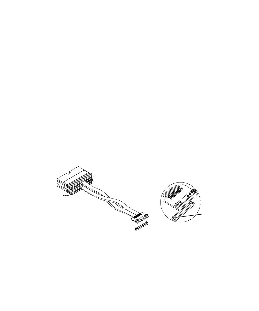
E5402A-pro series low-profile
right-angle 34-channel
single-ended
soft touch probe
(for analyzers with 90-pin cable connectors)
Cable egress
key
E5412A retention
module
Figure 2 E5402A-pro series right-angle single-ended soft touch probe
and E5412A retention module
14 E5400-Pro Series Soft Touch User’s Guide

Overview, Installation, and Selection of Probing Options 1
The E5404A-Pro Series 34-channel Single-ended Soft Touch Probe
(for analyzers with 40-pin cable connectors)
The Agilent E5404A- pro series probe is a 34-channel,
single- ended, soft touch probe compatible with the Agilent
logic analysis modules listed in Table 1 on page 12. It is
capable of capturing data up to the rated maximum state
(synchronous) analysis clock rates of all the supported
analyzers, with signal amplitudes as small as 500 mV
peak-to- peak. A retention module must be installed on the
target system board to attach the probe to the board.
A kit of five retention modules are supplied with each
probe. Refer to “Ordering retention modules" on page 13 for
information on ordering more.
See “Mechanical Considerations" on page 19 for
information on designing your target system board.
E5404A-pro series
34-channel
single-ended
soft touch probe
E5403A retention
module
Figure 3 E5404A-pro series single-ended soft touch probe and
E5403A retention module
E5400-Pro Series Soft Touch User’s Guide 15

1 Overview, Installation, and Selection of Probing Options
The E5405A-Pro Series 17-channel Differential Soft Touch Probe
(for analyzers with 90-pin cable connectors)
The Agilent E5405A- pro series probe is a 17-channel,
single- ended, soft touch probe compatible with the Agilent
logic analysis modules listed in Table 1 on page 12. It is
capable of capturing data up to the rated maximum state
(synchronous) analysis clock rates of all the supported
analyzers, with differential signal amplitudes as small as
200 mV peak- to- peak. A retention module must be installed
on the target system board to attach the probe to the board.
A kit of five retention modules are supplied with each
probe. Refer to “Ordering retention modules" on page 13 for
information on ordering more.
See “Mechanical Considerations" on page 19 for
information on designing your target system board.
Differential Input Amplitude
Definition
For differential signals, the
difference voltage Vmax - Vmin
must be greater than or equal to
200 mV p- p
E5405A-pro series
17-channel
differential
soft touch probe
E5403A retention
module
Figure 4 E5405A-pro series differential soft touch probe and
E5403A retention module
16 E5400-Pro Series Soft Touch User’s Guide
200 mV p-p

Overview, Installation, and Selection of Probing Options 1
The E5406A-Pro Series 34-channel Single-ended Soft Touch Probe
(for analyzers with 90-pin cable connectors)
The Agilent E5406A- pro series probe is a 34-channel,
single- ended, soft touch probe compatible with the Agilent
logic analysis modules listed in Table 1 on page 12. It is
capable of capturing data up to the rated maximum state
(synchronous) analysis clock rates of all the supported
analyzers, with signal amplitudes as small as 250 mV
peak-to- peak. A retention module must be installed on the
target system board to attach the probe to the board.
A kit of five retention modules are supplied with each
probe. Refer to “Ordering retention modules" on page 13 for
information on ordering more.
See “Mechanical Considerations" on page 19 for
information on designing your target system board.
E5406A-pro series
34-channel
single-ended
soft touch probe
E5403A retention
module
Figure 5 E5406A-pro series single-ended soft touch probe and
E5403A retention module
E5400-Pro Series Soft Touch User’s Guide 17

1 Overview, Installation, and Selection of Probing Options
The E5386A Half-channel Adapter (for use with the 16760A logic analyzer)
The E5386A Half-channel Adapter is intended to be used
with the Agilent 16760A logic analyzer in half-channel state
mode and supports the E5402A, E5405A, and E5406A
probes.
The E5386A Half-channel Adapter has its own ID code.
When using the adapter, the 16760A logic analyzer
recognizes its code rather than that of the probe which is
attached to the target. Therefore, the user interface format
menu doesn't automatically set thresholds to the proper
values. You need to go into the threshold menu and select
(differential, custom, or standard settings).
E5386A
half-channel adapter
When using the adapter in half- channel state mode:
• Clock-bits are not available in half- channel state mode
(although JCLK on the master is still used).
• Be sure to connect Master pod 1 of the logic analyzer to
the upper bits, 8- 15 + clk, on the half- channel adapter.
This is necessary to connect the clock in the system
under test to the logic analyzer system clock.
• Using the E5386A does not reduce the performance of the
16760A logic analyzer and the soft touch probes.
If the E5386A is used in full- channel state mode, the
thresholds on the unused (odd) bits are floating. This could
result in spurious activity indicators in the format menu.
18 E5400-Pro Series Soft Touch User’s Guide

Agilent E5400-Pro Series Soft Touch Connectorless Probes
User’s Guide
2
Mechanical Considerations
Characteristics 20
Probe Dimensions 21
Board Layout Dimensions 25
Pin Outs for the Probes 28
E5386A Half-channel Adapter Dimensions 36
Use the following mechanical information to design your
target system board.
A
19

2 Mechanical Considerations
Characteristics
Electrical considerations such as equivalent probe loads,
input impedance, and time domain transmission are shown
in chapters 3 and 4 of this manual. Other characteristics are
dependant on the logic analyzer module you are using.
20 E5400-Pro Series Soft Touch User’s Guide
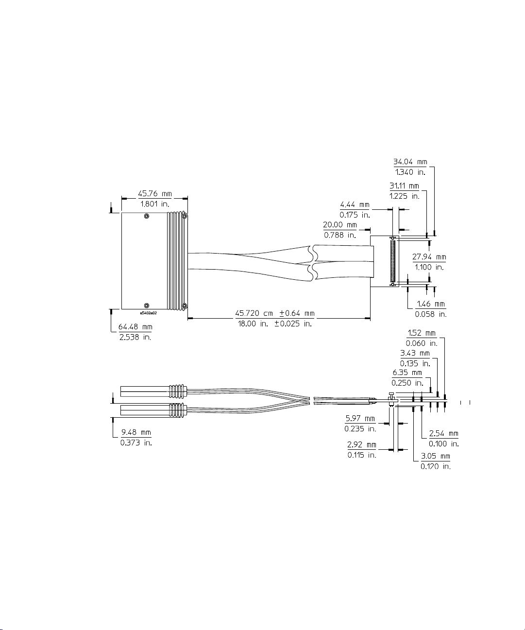
Probe Dimensions
Top view E5402A
Mechanical Considerations 2
The following figures show the dimensions of the Agilent
E5400- pro series soft touch probes.
Side view E5402A
Figure 6 E5402A probe dimensions
E5400-Pro Series Soft Touch User’s Guide 21

2 Mechanical Considerations
Top view E5404A
Side view E5404A
Figure 7 E5404A probe dimensions
22 E5400-Pro Series Soft Touch User’s Guide

Top view E5405A
Mechanical Considerations 2
Side view E5405A
Figure 8 E5405A probe dimensions
E5400-Pro Series Soft Touch User’s Guide 23
 Loading...