


Agilent E5061A/E5062A ENA Series RF Network Analyzers
Service Guide
Fifth Edition
Manufacturing No. E5061-90140
October 2008

Notices
The information contained in this document is subject to change without notice.
This document contains proprietary information that is protected by copyright. All rights
are reserved. No part of this document may be photocopied, reproduced, or translated to
another language without the prior written consent of Agilent Technologies.
Microsoft®,MS-DOS®,Windows®,Visual C++®,Visual Basic®,VBA® and Excel® are
registered
UNIX is a registered trademark in U.S. and other countries, licensed
exclusively through X/Open Company Limited.
Portions ©Copyright 1996, Microsoft Corporation. All rights reserved.
© Copyright 2004, 2005, 2007, 2008 Agilent Technologies
Manual Printing History
The manual’s printing date and part number indicate its current edition. The printing date
changes when a new edition is printed. (Minor corrections and updates that are
incorporated at reprint do not cause the date to change.) The manual part number changes
when extensive technical changes are incorporated.
February 2004 First Edition
September 2005 Second Edition (part number: E5061-90110, changes for firmeware
version A.02.00)
February 2007 Third Edition (part number: E5061-90120, changes for firmeware
version A.03.00)
May 2007 Fourth Edition (part number: E5061-90130)
October 2008 Fifth Edition (part number: E5061-90140)
2

Safety Summary
The following general safety precautions must be observed during all phases of operation,
service, and repair of this instrument. Failure to comply with these precautions or with
specific WARNINGS elsewhere in this manual may impair the protection provided by the
equipment. Such noncompliance would also violate safety standards of design,
manufacture, and intended use of the instrument. Agilent Technologies assumes no
liability for the customer’s failure to comply with these precautions.
NOTE The E5061A/E5062A complies with INSTALLATION CATEGORY II as well as
POLLUTION DEGREE 2 in IEC61010-1. The E5061A/E5062A is an INDOOR USE
product.
NOTE The LEDs in the E5061A/E5062A are Class 1 in accordance with IEC60825-1,
CLASS 1 LED PRODUCT
NOTE This equipment is MEASUREMENT CATEGORY I (CAT I). Do not use for CAT II, III,
or IV.
NOTE This equipment is tested with stand-alone condition or with the combination with the
accessories supplied by Agilent Technologies against the requirement of the standards
described in the Declaration of Conformity. If it is used as a system component,
compliance of related regulations and safety requirements are to be confirmed by the
builder of the system.
• Ground the Instrument
To avoid electric shock, the instrument chassis and cabinet must be grounded with the
supplied power cable’s grounding prong.
• DO NOT Operate in an Explosive Atmosphere
Do not operate the instrument in the presence of inflammable gasses or fumes.
Operation of any electrical instrument in such an environment clearly constitutes a
safety hazard.
• Keep Away from Live Circuits
Operators must not remove instrument covers. Component replacement and internal
adjustments must be made by qualified maintenance personnel. Do not replace
components with the power cable connected. Under certain conditions, dangerous
voltage levels may remain even after the power cable has been disconnected. To avoid
injuries, always disconnect the power and discharge circuits before touching them.
• DO NOT Service or Adjust the In strument Alone
Do not attempt internal service or adjustment unless another person, capable of
rendering first aid and resuscitation, is present.
• DO NO T Substitute Parts or Modify the Instrument
To avoid the danger of introducing additional hazards, do not install substitute parts or
perform unauthorized modifications to the instrument. Return the instrument to an
3

Agilent Technologies Sales and Service Office for service and repair to ensure that
safety features are maintained in operational condition.
• Dangerous Procedure Warnings
Warnings, such as the example below, precede potentially dangerous procedures
throughout this manual. Instructions contained in the warnings must be followed.
WARNING Dangerous voltage levels, capable of causing death, are present in this instrument.
Use extreme caution when handling, testing, and adjusting this instrument.
• Do no t connect the measuring terminals to m ains.
Safety Symbol
General definitions of safety symbols used on the instrument or in manuals are listed
below.
Instruction Manual symbol: the product is marked with this symbol when it is necessary for
the user to refer to the instrument manual.
Alternating current.
Direct current.
On (Supply).
Off (Supply).
In position of push-button switch.
Out position of push-button switch.
Frame (or chassis) terminal. A connection to the frame (chassis) of the equipment which
normally include all exposed metal structure.
Stand-by.
WARNING This warning sign denotes a hazard. It calls attention to a procedure, practice,
condition or the like, which, if not correctly performed or adhered to, could result in
injury or death to personnel.
CAUTION This Caution sign denotes a hazard. It calls attention to a procedure, practice, condition or
the like, which, if not correctly performed or adhered to, could result in damage to or
destruction of part or all of the product.
NOTE Note denotes important information. It calls attention to a procedure, practice, condition or
the like, which is essential to highlight.
4

Certification
Agilent Technologies certifies that this product met its published specifications at the time
of shipment from the factory. Agilent Technologies further certifies that its calibration
measurements are traceable to the United States National Institute of Standards and
Technology, to the extent allowed by the Institution’s calibration facility, or to the
calibration facilities of other International Standards Organization members.
Documentation Warranty
The material contained in this document is provided "as is," and is subject to being
changed, without notice, in future editions. Further, to the maximum extent permitted by
applicable law, Agilent disclaims all warranties, either express or implied with regard to
this manual and any information contained herein, including but not limited to the implied
warranties of merchantability and fitness for a particular purpose. Agilent shall not be
liable for errors or for incidental or consequential damages in connection with the
furnishing, use, or performance of this document or any information contained herei n.
Should Agilent and the user have a separate written agreement with warranty terms
covering the material in this document that conflict with these terms, the warranty terms in
the separate agreement will control.
Exclusive Remedies
The remedies provided herein are buyer’s sole and exclusive remedies. Agilent
T echnologies shall not be liable for any direct, indirect, special, incidental, or
consequential damages, whether based on contract, tort, or any other legal theory.
Assistance
Product maintenance agreements and other customer assistance agreements are available
for Agilent Technologies products.
For any assistance, contact your nearest Agilent Technologies Sales and Service Office.
Addresses are provided at the back of this manual.
5

Typeface Conventions
Sample (bold) Boldface type is used when a term is defined or
emphasised.
Sample (Italic) Italic type is used for emphasis.
key Indicates a hardkey (key on the front panel or
external keyboard) labeled “Sample.” “key” may
be omitted.
Sample menu/button/box Indicates a menu/button/box on the screen labeled
“Sample” which can be selected/executed by
clicking. “menu,” “button,” or “box” may be
omitted.
Sample block/toolbar Indicates a block (group of hardkeys) or a toolbar
(setup toolbar) labeled “Sample.”
Sample 1 - Sample 2 - Sample 3 Indicates a sequential operation of Sample 1,
Sample 2, and Sample 3 (menu, button, or box).
“-” may be omitted.
6

1. General Information
Precautions . . . . . . . . . . . . . . . . . . . . . . . . . . . . . . . . . . . . . . . . . . . . . . . . . . . . . . . . . . . . . . . . . . . . . . . . . . 14
Software Installed . . . . . . . . . . . . . . . . . . . . . . . . . . . . . . . . . . . . . . . . . . . . . . . . . . . . . . . . . . . . . . . . . . . 14
Organization of Service Guide . . . . . . . . . . . . . . . . . . . . . . . . . . . . . . . . . . . . . . . . . . . . . . . . . . . . . . . . . . . 15
Instrument Covered by This Manual . . . . . . . . . . . . . . . . . . . . . . . . . . . . . . . . . . . . . . . . . . . . . . . . . . . . . . 17
Required Equipment . . . . . . . . . . . . . . . . . . . . . . . . . . . . . . . . . . . . . . . . . . . . . . . . . . . . . . . . . . . . . . . . . . . 18
Power Meter Accuracy Test . . . . . . . . . . . . . . . . . . . . . . . . . . . . . . . . . . . . . . . . . . . . . . . . . . . . . . . . . . . 20
2. Performance Tests
Introduction. . . . . . . . . . . . . . . . . . . . . . . . . . . . . . . . . . . . . . . . . . . . . . . . . . . . . . . . . . . . . . . . . . . . . . . . . . 26
Test Equipment Required . . . . . . . . . . . . . . . . . . . . . . . . . . . . . . . . . . . . . . . . . . . . . . . . . . . . . . . . . . . . . 26
Instruction for Using the Performance Test Software. . . . . . . . . . . . . . . . . . . . . . . . . . . . . . . . . . . . . . . . . . 27
Setting system controller (USB/GPIB interface) . . . . . . . . . . . . . . . . . . . . . . . . . . . . . . . . . . . . . . . . . . . 27
Setting the GPIB address of the equipment . . . . . . . . . . . . . . . . . . . . . . . . . . . . . . . . . . . . . . . . . . . . . . . 29
Setting up the E4419B Power Meter . . . . . . . . . . . . . . . . . . . . . . . . . . . . . . . . . . . . . . . . . . . . . . . . . . . . 29
Running the Performance Tests. . . . . . . . . . . . . . . . . . . . . . . . . . . . . . . . . . . . . . . . . . . . . . . . . . . . . . . . . 30
Program Overall . . . . . . . . . . . . . . . . . . . . . . . . . . . . . . . . . . . . . . . . . . . . . . . . . . . . . . . . . . . . . . . . . . . . 31
Individual Test Description. . . . . . . . . . . . . . . . . . . . . . . . . . . . . . . . . . . . . . . . . . . . . . . . . . . . . . . . . . . . . . 33
1. Frequency Accuracy Test . . . . . . . . . . . . . . . . . . . . . . . . . . . . . . . . . . . . . . . . . . . . . . . . . . . . . . . . . . . 33
2. RF Output Level Accuracy and Flatness Test. . . . . . . . . . . . . . . . . . . . . . . . . . . . . . . . . . . . . . . . . . . . 33
3. RF Output Level Linearity Test . . . . . . . . . . . . . . . . . . . . . . . . . . . . . . . . . . . . . . . . . . . . . . . . . . . . . . 34
4. Trace Noise Test . . . . . . . . . . . . . . . . . . . . . . . . . . . . . . . . . . . . . . . . . . . . . . . . . . . . . . . . . . . . . . . . . . 34
5. Crosstalk & System Dynamic Range Test . . . . . . . . . . . . . . . . . . . . . . . . . . . . . . . . . . . . . . . . . . . . . . 34
6. Dynamic Accuracy Test . . . . . . . . . . . . . . . . . . . . . . . . . . . . . . . . . . . . . . . . . . . . . . . . . . . . . . . . . . . . 35
7. Uncorrected System Performance Test . . . . . . . . . . . . . . . . . . . . . . . . . . . . . . . . . . . . . . . . . . . . . . . . . 36
E5061A Performance Test Record (for Option 150/250). . . . . . . . . . . . . . . . . . . . . . . . . . . . . . . . . . . . . . . 37
Frequency Accuracy Test . . . . . . . . . . . . . . . . . . . . . . . . . . . . . . . . . . . . . . . . . . . . . . . . . . . . . . . . . . . . . 37
RF Output Level Accuracy and Flatness Test. . . . . . . . . . . . . . . . . . . . . . . . . . . . . . . . . . . . . . . . . . . . . . 37
RF Output Level Linearity Test (@ Port1) . . . . . . . . . . . . . . . . . . . . . . . . . . . . . . . . . . . . . . . . . . . . . . . . 38
RF Output Level Linearity Test (@ Port2)(Option 250 only). . . . . . . . . . . . . . . . . . . . . . . . . . . . . . . . . . 39
Trace Noise Test . . . . . . . . . . . . . . . . . . . . . . . . . . . . . . . . . . . . . . . . . . . . . . . . . . . . . . . . . . . . . . . . . . . . 40
Crosstalk Test . . . . . . . . . . . . . . . . . . . . . . . . . . . . . . . . . . . . . . . . . . . . . . . . . . . . . . . . . . . . . . . . . . . . . . 42
System Dynamic Range Test. . . . . . . . . . . . . . . . . . . . . . . . . . . . . . . . . . . . . . . . . . . . . . . . . . . . . . . . . . . 42
Dynamic Accuracy Test . . . . . . . . . . . . . . . . . . . . . . . . . . . . . . . . . . . . . . . . . . . . . . . . . . . . . . . . . . . . . . 43
Uncorrected System Performance Test . . . . . . . . . . . . . . . . . . . . . . . . . . . . . . . . . . . . . . . . . . . . . . . . . . . 45
E5061A Performance Test Record (for Option 175/275). . . . . . . . . . . . . . . . . . . . . . . . . . . . . . . . . . . . . . . 47
Frequency Accuracy Test . . . . . . . . . . . . . . . . . . . . . . . . . . . . . . . . . . . . . . . . . . . . . . . . . . . . . . . . . . . . . 47
RF Output Level Accuracy and Flatness Test. . . . . . . . . . . . . . . . . . . . . . . . . . . . . . . . . . . . . . . . . . . . . . 47
RF Output Level Linearity Test (@ Port1) . . . . . . . . . . . . . . . . . . . . . . . . . . . . . . . . . . . . . . . . . . . . . . . . 48
RF Output Level Linearity Test (@ Port2)(Option 275 only). . . . . . . . . . . . . . . . . . . . . . . . . . . . . . . . . . 49
Trace Noise Test . . . . . . . . . . . . . . . . . . . . . . . . . . . . . . . . . . . . . . . . . . . . . . . . . . . . . . . . . . . . . . . . . . . . 50
Crosstalk Test . . . . . . . . . . . . . . . . . . . . . . . . . . . . . . . . . . . . . . . . . . . . . . . . . . . . . . . . . . . . . . . . . . . . . . 52
System Dynamic Range Test. . . . . . . . . . . . . . . . . . . . . . . . . . . . . . . . . . . . . . . . . . . . . . . . . . . . . . . . . . . 52
Dynamic Accuracy Test . . . . . . . . . . . . . . . . . . . . . . . . . . . . . . . . . . . . . . . . . . . . . . . . . . . . . . . . . . . . . . 53
Uncorrected System Performance Test . . . . . . . . . . . . . . . . . . . . . . . . . . . . . . . . . . . . . . . . . . . . . . . . . . . 55
E5062A Performance Test Record (for Option 150/250). . . . . . . . . . . . . . . . . . . . . . . . . . . . . . . . . . . . . . . 57
Frequency Accuracy Test . . . . . . . . . . . . . . . . . . . . . . . . . . . . . . . . . . . . . . . . . . . . . . . . . . . . . . . . . . . . . 57
RF Output Level Accuracy and Flatness Test. . . . . . . . . . . . . . . . . . . . . . . . . . . . . . . . . . . . . . . . . . . . . . 57
RF Output Level Linearity Test (@ Port1) . . . . . . . . . . . . . . . . . . . . . . . . . . . . . . . . . . . . . . . . . . . . . . . . 59
Contents
7

Contents
RF Output Level Linearity Test (@ Port2)(Option 250 only) . . . . . . . . . . . . . . . . . . . . . . . . . . . . . . . . . 60
Trace Noise Test . . . . . . . . . . . . . . . . . . . . . . . . . . . . . . . . . . . . . . . . . . . . . . . . . . . . . . . . . . . . . . . . . . . . 61
Crosstalk Test . . . . . . . . . . . . . . . . . . . . . . . . . . . . . . . . . . . . . . . . . . . . . . . . . . . . . . . . . . . . . . . . . . . . . . 63
System Dynamic Range Test . . . . . . . . . . . . . . . . . . . . . . . . . . . . . . . . . . . . . . . . . . . . . . . . . . . . . . . . . . 63
Dynamic Accuracy Test . . . . . . . . . . . . . . . . . . . . . . . . . . . . . . . . . . . . . . . . . . . . . . . . . . . . . . . . . . . . . . 65
Uncorrected System Performance Test. . . . . . . . . . . . . . . . . . . . . . . . . . . . . . . . . . . . . . . . . . . . . . . . . . . 66
E5062A Performance Test Record (for Option 175/275). . . . . . . . . . . . . . . . . . . . . . . . . . . . . . . . . . . . . . . 69
Frequency Accuracy Test . . . . . . . . . . . . . . . . . . . . . . . . . . . . . . . . . . . . . . . . . . . . . . . . . . . . . . . . . . . . . 69
RF Output Level Accuracy and Flatness Test. . . . . . . . . . . . . . . . . . . . . . . . . . . . . . . . . . . . . . . . . . . . . . 69
RF Output Level Linearity Test (@ Port1). . . . . . . . . . . . . . . . . . . . . . . . . . . . . . . . . . . . . . . . . . . . . . . . 71
RF Output Level Linearity Test (@ Port2)(Option 275 only) . . . . . . . . . . . . . . . . . . . . . . . . . . . . . . . . . 72
Trace Noise Test . . . . . . . . . . . . . . . . . . . . . . . . . . . . . . . . . . . . . . . . . . . . . . . . . . . . . . . . . . . . . . . . . . . . 73
Crosstalk Test . . . . . . . . . . . . . . . . . . . . . . . . . . . . . . . . . . . . . . . . . . . . . . . . . . . . . . . . . . . . . . . . . . . . . . 75
System Dynamic Range Test . . . . . . . . . . . . . . . . . . . . . . . . . . . . . . . . . . . . . . . . . . . . . . . . . . . . . . . . . . 75
Dynamic Accuracy Test . . . . . . . . . . . . . . . . . . . . . . . . . . . . . . . . . . . . . . . . . . . . . . . . . . . . . . . . . . . . . . 76
Uncorrected System Performance Test. . . . . . . . . . . . . . . . . . . . . . . . . . . . . . . . . . . . . . . . . . . . . . . . . . . 78
3. Adjustment
Safety Considerations. . . . . . . . . . . . . . . . . . . . . . . . . . . . . . . . . . . . . . . . . . . . . . . . . . . . . . . . . . . . . . . . . . 82
Warm-up for Adjustment . . . . . . . . . . . . . . . . . . . . . . . . . . . . . . . . . . . . . . . . . . . . . . . . . . . . . . . . . . . . . . . 82
Required Equipment. . . . . . . . . . . . . . . . . . . . . . . . . . . . . . . . . . . . . . . . . . . . . . . . . . . . . . . . . . . . . . . . . . . 82
Required Adjustment after Replacing Assembly . . . . . . . . . . . . . . . . . . . . . . . . . . . . . . . . . . . . . . . . . . . . . 83
Writing ID. . . . . . . . . . . . . . . . . . . . . . . . . . . . . . . . . . . . . . . . . . . . . . . . . . . . . . . . . . . . . . . . . . . . . . . . . 83
Frequency Reference Adjustment. . . . . . . . . . . . . . . . . . . . . . . . . . . . . . . . . . . . . . . . . . . . . . . . . . . . . . . 83
Synthesizer Gain Adjustment . . . . . . . . . . . . . . . . . . . . . . . . . . . . . . . . . . . . . . . . . . . . . . . . . . . . . . . . . . 84
Local Output Power Adjustment . . . . . . . . . . . . . . . . . . . . . . . . . . . . . . . . . . . . . . . . . . . . . . . . . . . . . . . 84
Source Output Power Adjustment . . . . . . . . . . . . . . . . . . . . . . . . . . . . . . . . . . . . . . . . . . . . . . . . . . . . . . 84
Receiver IF Range Adjustment. . . . . . . . . . . . . . . . . . . . . . . . . . . . . . . . . . . . . . . . . . . . . . . . . . . . . . . . . 85
Receiver Ports Characteristics Adjustment. . . . . . . . . . . . . . . . . . . . . . . . . . . . . . . . . . . . . . . . . . . . . . . . 85
4. Troubleshooting
Introduction . . . . . . . . . . . . . . . . . . . . . . . . . . . . . . . . . . . . . . . . . . . . . . . . . . . . . . . . . . . . . . . . . . . . . . . . . 88
How to exit from the E5061A/E5062A Measurement View . . . . . . . . . . . . . . . . . . . . . . . . . . . . . . . . . . . . 89
To Troubleshoot the Instrument . . . . . . . . . . . . . . . . . . . . . . . . . . . . . . . . . . . . . . . . . . . . . . . . . . . . . . . . . . 90
Primary Trouble Isolation. . . . . . . . . . . . . . . . . . . . . . . . . . . . . . . . . . . . . . . . . . . . . . . . . . . . . . . . . . . . . 90
No Display troubleshooting . . . . . . . . . . . . . . . . . . . . . . . . . . . . . . . . . . . . . . . . . . . . . . . . . . . . . . . . . . . . . 92
Booting Process Troubleshooting. . . . . . . . . . . . . . . . . . . . . . . . . . . . . . . . . . . . . . . . . . . . . . . . . . . . . . . . . 95
Troubleshooting Using Diagnostic Test . . . . . . . . . . . . . . . . . . . . . . . . . . . . . . . . . . . . . . . . . . . . . . . . . . . 100
Power On Self Test . . . . . . . . . . . . . . . . . . . . . . . . . . . . . . . . . . . . . . . . . . . . . . . . . . . . . . . . . . . . . . . . . 100
PLL unlock . . . . . . . . . . . . . . . . . . . . . . . . . . . . . . . . . . . . . . . . . . . . . . . . . . . . . . . . . . . . . . . . . . . . . . . 100
Contents of the diagnostic test . . . . . . . . . . . . . . . . . . . . . . . . . . . . . . . . . . . . . . . . . . . . . . . . . . . . . . . . 100
Test equipment required for diagnostic test . . . . . . . . . . . . . . . . . . . . . . . . . . . . . . . . . . . . . . . . . . . . . . 101
To Execute the Diagnostic Test. . . . . . . . . . . . . . . . . . . . . . . . . . . . . . . . . . . . . . . . . . . . . . . . . . . . . . . . 101
Program Overall . . . . . . . . . . . . . . . . . . . . . . . . . . . . . . . . . . . . . . . . . . . . . . . . . . . . . . . . . . . . . . . . . . . 102
Diagnostic Test Failure Troubleshooting . . . . . . . . . . . . . . . . . . . . . . . . . . . . . . . . . . . . . . . . . . . . . . . . 104
Function Specific Troubleshooting . . . . . . . . . . . . . . . . . . . . . . . . . . . . . . . . . . . . . . . . . . . . . . . . . . . . . . 106
To Check the Device Driver . . . . . . . . . . . . . . . . . . . . . . . . . . . . . . . . . . . . . . . . . . . . . . . . . . . . . . . . . . 107
To Check the Front Panel . . . . . . . . . . . . . . . . . . . . . . . . . . . . . . . . . . . . . . . . . . . . . . . . . . . . . . . . . . . . 109
8

Contents
To Check the Touch Panel (Option 016 only). . . . . . . . . . . . . . . . . . . . . . . . . . . . . . . . . . . . . . . . . . . . . 110
To Check the LCD. . . . . . . . . . . . . . . . . . . . . . . . . . . . . . . . . . . . . . . . . . . . . . . . . . . . . . . . . . . . . . . . . . 110
To Check the External Keyboard . . . . . . . . . . . . . . . . . . . . . . . . . . . . . . . . . . . . . . . . . . . . . . . . . . . . . . 111
To Check the Mouse . . . . . . . . . . . . . . . . . . . . . . . . . . . . . . . . . . . . . . . . . . . . . . . . . . . . . . . . . . . . . . . . 111
To Check the FDD. . . . . . . . . . . . . . . . . . . . . . . . . . . . . . . . . . . . . . . . . . . . . . . . . . . . . . . . . . . . . . . . . . 111
To Check the Video output . . . . . . . . . . . . . . . . . . . . . . . . . . . . . . . . . . . . . . . . . . . . . . . . . . . . . . . . . . . 112
To Check the External Trigger Input. . . . . . . . . . . . . . . . . . . . . . . . . . . . . . . . . . . . . . . . . . . . . . . . . . . . 112
To Check the LAN . . . . . . . . . . . . . . . . . . . . . . . . . . . . . . . . . . . . . . . . . . . . . . . . . . . . . . . . . . . . . . . . . 112
To Check the Printer Parallel Port. . . . . . . . . . . . . . . . . . . . . . . . . . . . . . . . . . . . . . . . . . . . . . . . . . . . . . 116
To Check the GPIB . . . . . . . . . . . . . . . . . . . . . . . . . . . . . . . . . . . . . . . . . . . . . . . . . . . . . . . . . . . . . . . . . 116
Performance test failure troubleshooting . . . . . . . . . . . . . . . . . . . . . . . . . . . . . . . . . . . . . . . . . . . . . . . . . . 118
Recommended adjustment for performance test failure . . . . . . . . . . . . . . . . . . . . . . . . . . . . . . . . . . . . . 118
Performance test failure troubleshooting . . . . . . . . . . . . . . . . . . . . . . . . . . . . . . . . . . . . . . . . . . . . . . . . 118
To configure the A20 Digital Motherboard and BIOS . . . . . . . . . . . . . . . . . . . . . . . . . . . . . . . . . . . . . . . . 120
To Identify the Motherboard Installed . . . . . . . . . . . . . . . . . . . . . . . . . . . . . . . . . . . . . . . . . . . . . . . . . . 120
Configure the Motherboard. . . . . . . . . . . . . . . . . . . . . . . . . . . . . . . . . . . . . . . . . . . . . . . . . . . . . . . . . . . 120
Testing DRAM on the Motherboard . . . . . . . . . . . . . . . . . . . . . . . . . . . . . . . . . . . . . . . . . . . . . . . . . . . . 120
To Confirm or Set the BIOS Options . . . . . . . . . . . . . . . . . . . . . . . . . . . . . . . . . . . . . . . . . . . . . . . . . . . 121
5. Replaceable Parts
Ordering Information . . . . . . . . . . . . . . . . . . . . . . . . . . . . . . . . . . . . . . . . . . . . . . . . . . . . . . . . . . . . . . . . . 128
Direct Mail Order System. . . . . . . . . . . . . . . . . . . . . . . . . . . . . . . . . . . . . . . . . . . . . . . . . . . . . . . . . . . . 128
Exchange Assemblies. . . . . . . . . . . . . . . . . . . . . . . . . . . . . . . . . . . . . . . . . . . . . . . . . . . . . . . . . . . . . . . . . 128
Replaceable Parts List. . . . . . . . . . . . . . . . . . . . . . . . . . . . . . . . . . . . . . . . . . . . . . . . . . . . . . . . . . . . . . . . . 129
Power Cables and Plug Configurations. . . . . . . . . . . . . . . . . . . . . . . . . . . . . . . . . . . . . . . . . . . . . . . . . . 129
Top View (Major Assemblies) . . . . . . . . . . . . . . . . . . . . . . . . . . . . . . . . . . . . . . . . . . . . . . . . . . . . . . . . 130
Top View (Cables). . . . . . . . . . . . . . . . . . . . . . . . . . . . . . . . . . . . . . . . . . . . . . . . . . . . . . . . . . . . . . . . . . 132
Top View (Under Power Supply) for E5061A : JP1KLxxxxx, MY44101900 and below, E5062A :
JP1KLxxxxx, MY44102842 and below.. . . . . . . . . . . . . . . . . . . . . . . . . . . . . . . . . . . . . . . . . . . . . . . . . 134
T op View (Under Power Supply) for E5061A : MY44101901 and above, E5062A : MY44102843 and above
136
Top View (Miscellaneous Parts) . . . . . . . . . . . . . . . . . . . . . . . . . . . . . . . . . . . . . . . . . . . . . . . . . . . . . . . 138
Front View (Analog Boards) . . . . . . . . . . . . . . . . . . . . . . . . . . . . . . . . . . . . . . . . . . . . . . . . . . . . . . . . . 140
Front View (Semirigid Cables) . . . . . . . . . . . . . . . . . . . . . . . . . . . . . . . . . . . . . . . . . . . . . . . . . . . . . . . . 141
Front Panel . . . . . . . . . . . . . . . . . . . . . . . . . . . . . . . . . . . . . . . . . . . . . . . . . . . . . . . . . . . . . . . . . . . . . . . 142
Rear View . . . . . . . . . . . . . . . . . . . . . . . . . . . . . . . . . . . . . . . . . . . . . . . . . . . . . . . . . . . . . . . . . . . . . . . . 144
Cover Assembly . . . . . . . . . . . . . . . . . . . . . . . . . . . . . . . . . . . . . . . . . . . . . . . . . . . . . . . . . . . . . . . . . . . 145
A28 FDD Assembly . . . . . . . . . . . . . . . . . . . . . . . . . . . . . . . . . . . . . . . . . . . . . . . . . . . . . . . . . . . . . . . . 146
A27 HDD Assembly . . . . . . . . . . . . . . . . . . . . . . . . . . . . . . . . . . . . . . . . . . . . . . . . . . . . . . . . . . . . . . . . 147
A21 PCI DSP CARD / A24 GPIB CARD Assembly. . . . . . . . . . . . . . . . . . . . . . . . . . . . . . . . . . . . . . . 148
Analog Mother Board Assembly. . . . . . . . . . . . . . . . . . . . . . . . . . . . . . . . . . . . . . . . . . . . . . . . . . . . . . . 149
Power Supply Assembly . . . . . . . . . . . . . . . . . . . . . . . . . . . . . . . . . . . . . . . . . . . . . . . . . . . . . . . . . . . . . 150
Chassis Assembly . . . . . . . . . . . . . . . . . . . . . . . . . . . . . . . . . . . . . . . . . . . . . . . . . . . . . . . . . . . . . . . . . . 151
Front Assembly (Front Keyboard / USB). . . . . . . . . . . . . . . . . . . . . . . . . . . . . . . . . . . . . . . . . . . . . . . . 152
Front Assembly (Inverter). . . . . . . . . . . . . . . . . . . . . . . . . . . . . . . . . . . . . . . . . . . . . . . . . . . . . . . . . . . . 153
Front Assembly (LCD) for E5061A : JP1KLxxxxx, MY44101900 and below, E5062A : JP1KLxxxxx,
MY44102842 and below. . . . . . . . . . . . . . . . . . . . . . . . . . . . . . . . . . . . . . . . . . . . . . . . . . . . . . . . . . . . . 154
Front Assembly (LCD) for E5061A : MY44101901 and above, E5062A : MY44102843 and above . 155
Front Assembly (Standby Switch / LCD Cable) for E5061A : JP1KLxxxxx, MY44101900 and below,
9

Contents
E5062A : JP1KLxxxxx, MY44102842 and below. . . . . . . . . . . . . . . . . . . . . . . . . . . . . . . . . . . . . . . . . 156
Front Assembly (Standby Switch / LCD Cable) for E5061A : MY44101901 and above, E5062A :
MY44102843 and above. . . . . . . . . . . . . . . . . . . . . . . . . . . . . . . . . . . . . . . . . . . . . . . . . . . . . . . . . . . . . 157
Front Assembly (Cover 1) . . . . . . . . . . . . . . . . . . . . . . . . . . . . . . . . . . . . . . . . . . . . . . . . . . . . . . . . . . . 158
Front Assembly (Cover 2) . . . . . . . . . . . . . . . . . . . . . . . . . . . . . . . . . . . . . . . . . . . . . . . . . . . . . . . . . . . 159
Front Assembly (Cover 3) . . . . . . . . . . . . . . . . . . . . . . . . . . . . . . . . . . . . . . . . . . . . . . . . . . . . . . . . . . . 160
Label on Rear Face. . . . . . . . . . . . . . . . . . . . . . . . . . . . . . . . . . . . . . . . . . . . . . . . . . . . . . . . . . . . . . . . . 161
Other Parts . . . . . . . . . . . . . . . . . . . . . . . . . . . . . . . . . . . . . . . . . . . . . . . . . . . . . . . . . . . . . . . . . . . . . . . 162
6. Replacement Procedure
Replacing an Assembly . . . . . . . . . . . . . . . . . . . . . . . . . . . . . . . . . . . . . . . . . . . . . . . . . . . . . . . . . . . . . . . 164
Required Tools . . . . . . . . . . . . . . . . . . . . . . . . . . . . . . . . . . . . . . . . . . . . . . . . . . . . . . . . . . . . . . . . . . . . . . 165
Outer Cover Removal. . . . . . . . . . . . . . . . . . . . . . . . . . . . . . . . . . . . . . . . . . . . . . . . . . . . . . . . . . . . . . . . . 166
Tools Required . . . . . . . . . . . . . . . . . . . . . . . . . . . . . . . . . . . . . . . . . . . . . . . . . . . . . . . . . . . . . . . . . . . . 166
Procedure . . . . . . . . . . . . . . . . . . . . . . . . . . . . . . . . . . . . . . . . . . . . . . . . . . . . . . . . . . . . . . . . . . . . . . . . 166
Front Panel Removal . . . . . . . . . . . . . . . . . . . . . . . . . . . . . . . . . . . . . . . . . . . . . . . . . . . . . . . . . . . . . . . . . 167
Tools required . . . . . . . . . . . . . . . . . . . . . . . . . . . . . . . . . . . . . . . . . . . . . . . . . . . . . . . . . . . . . . . . . . . . . 167
Procedure . . . . . . . . . . . . . . . . . . . . . . . . . . . . . . . . . . . . . . . . . . . . . . . . . . . . . . . . . . . . . . . . . . . . . . . . 167
A27 HDD (Hard Disk Drive) Replacement . . . . . . . . . . . . . . . . . . . . . . . . . . . . . . . . . . . . . . . . . . . . . . . . 169
Tools Required . . . . . . . . . . . . . . . . . . . . . . . . . . . . . . . . . . . . . . . . . . . . . . . . . . . . . . . . . . . . . . . . . . . . 169
Removal Procedure. . . . . . . . . . . . . . . . . . . . . . . . . . . . . . . . . . . . . . . . . . . . . . . . . . . . . . . . . . . . . . . . . 169
Replacement Procedure . . . . . . . . . . . . . . . . . . . . . . . . . . . . . . . . . . . . . . . . . . . . . . . . . . . . . . . . . . . . . 170
Restore Backup Files onto the New HDD . . . . . . . . . . . . . . . . . . . . . . . . . . . . . . . . . . . . . . . . . . . . . . . 170
Calibration of the Touch Screen . . . . . . . . . . . . . . . . . . . . . . . . . . . . . . . . . . . . . . . . . . . . . . . . . . . . . . . 170
A28 FDD (Floppy Disk Drive) Replacement. . . . . . . . . . . . . . . . . . . . . . . . . . . . . . . . . . . . . . . . . . . . . . . 172
Tools Required . . . . . . . . . . . . . . . . . . . . . . . . . . . . . . . . . . . . . . . . . . . . . . . . . . . . . . . . . . . . . . . . . . . . 172
Removal procedure. . . . . . . . . . . . . . . . . . . . . . . . . . . . . . . . . . . . . . . . . . . . . . . . . . . . . . . . . . . . . . . . . 172
Replacement Procedure . . . . . . . . . . . . . . . . . . . . . . . . . . . . . . . . . . . . . . . . . . . . . . . . . . . . . . . . . . . . . 172
A50 ATX Power Supply Assembly Replacement . . . . . . . . . . . . . . . . . . . . . . . . . . . . . . . . . . . . . . . . . . . 173
Tools Required . . . . . . . . . . . . . . . . . . . . . . . . . . . . . . . . . . . . . . . . . . . . . . . . . . . . . . . . . . . . . . . . . . . . 173
Removal Procedure. . . . . . . . . . . . . . . . . . . . . . . . . . . . . . . . . . . . . . . . . . . . . . . . . . . . . . . . . . . . . . . . . 173
Replacement Procedure . . . . . . . . . . . . . . . . . . . . . . . . . . . . . . . . . . . . . . . . . . . . . . . . . . . . . . . . . . . . . 173
A25 Handler I/O Board Replacement . . . . . . . . . . . . . . . . . . . . . . . . . . . . . . . . . . . . . . . . . . . . . . . . . . . . 175
Tools Required . . . . . . . . . . . . . . . . . . . . . . . . . . . . . . . . . . . . . . . . . . . . . . . . . . . . . . . . . . . . . . . . . . . . 175
Removal Procedure. . . . . . . . . . . . . . . . . . . . . . . . . . . . . . . . . . . . . . . . . . . . . . . . . . . . . . . . . . . . . . . . . 175
Replacement Procedure . . . . . . . . . . . . . . . . . . . . . . . . . . . . . . . . . . . . . . . . . . . . . . . . . . . . . . . . . . . . . 175
A20 Digital Motherboard Replacement . . . . . . . . . . . . . . . . . . . . . . . . . . . . . . . . . . . . . . . . . . . . . . . . . . . 176
Tools Required . . . . . . . . . . . . . . . . . . . . . . . . . . . . . . . . . . . . . . . . . . . . . . . . . . . . . . . . . . . . . . . . . . . . 176
Removal Procedure. . . . . . . . . . . . . . . . . . . . . . . . . . . . . . . . . . . . . . . . . . . . . . . . . . . . . . . . . . . . . . . . . 176
Replacement Procedure . . . . . . . . . . . . . . . . . . . . . . . . . . . . . . . . . . . . . . . . . . . . . . . . . . . . . . . . . . . . . 176
A1 Source Board Replacement . . . . . . . . . . . . . . . . . . . . . . . . . . . . . . . . . . . . . . . . . . . . . . . . . . . . . . . . . 178
Tools Required . . . . . . . . . . . . . . . . . . . . . . . . . . . . . . . . . . . . . . . . . . . . . . . . . . . . . . . . . . . . . . . . . . . . 178
Removal Procedure. . . . . . . . . . . . . . . . . . . . . . . . . . . . . . . . . . . . . . . . . . . . . . . . . . . . . . . . . . . . . . . . . 178
Replacement Procedure . . . . . . . . . . . . . . . . . . . . . . . . . . . . . . . . . . . . . . . . . . . . . . . . . . . . . . . . . . . . . 178
A2 Receiver Board Replacement . . . . . . . . . . . . . . . . . . . . . . . . . . . . . . . . . . . . . . . . . . . . . . . . . . . . . . . . 180
Tools Required . . . . . . . . . . . . . . . . . . . . . . . . . . . . . . . . . . . . . . . . . . . . . . . . . . . . . . . . . . . . . . . . . . . . 180
Removal Procedure. . . . . . . . . . . . . . . . . . . . . . . . . . . . . . . . . . . . . . . . . . . . . . . . . . . . . . . . . . . . . . . . . 180
Replacement Procedure . . . . . . . . . . . . . . . . . . . . . . . . . . . . . . . . . . . . . . . . . . . . . . . . . . . . . . . . . . . . . 180
Fan Replacement . . . . . . . . . . . . . . . . . . . . . . . . . . . . . . . . . . . . . . . . . . . . . . . . . . . . . . . . . . . . . . . . . . . . 181
10

Contents
Tools Required . . . . . . . . . . . . . . . . . . . . . . . . . . . . . . . . . . . . . . . . . . . . . . . . . . . . . . . . . . . . . . . . . . . . 181
Removal Procedure. . . . . . . . . . . . . . . . . . . . . . . . . . . . . . . . . . . . . . . . . . . . . . . . . . . . . . . . . . . . . . . . . 181
Replacement Procedure . . . . . . . . . . . . . . . . . . . . . . . . . . . . . . . . . . . . . . . . . . . . . . . . . . . . . . . . . . . . . . 181
A10 Analog Motherboard Replacement. . . . . . . . . . . . . . . . . . . . . . . . . . . . . . . . . . . . . . . . . . . . . . . . . . . 182
Tools Required . . . . . . . . . . . . . . . . . . . . . . . . . . . . . . . . . . . . . . . . . . . . . . . . . . . . . . . . . . . . . . . . . . . . 182
Removal Procedure. . . . . . . . . . . . . . . . . . . . . . . . . . . . . . . . . . . . . . . . . . . . . . . . . . . . . . . . . . . . . . . . . 182
Replacement Procedure . . . . . . . . . . . . . . . . . . . . . . . . . . . . . . . . . . . . . . . . . . . . . . . . . . . . . . . . . . . . . . 182
A21 PCI DSP Card / A24 GPIB Card Replacement . . . . . . . . . . . . . . . . . . . . . . . . . . . . . . . . . . . . . . . . . 183
Tools Required . . . . . . . . . . . . . . . . . . . . . . . . . . . . . . . . . . . . . . . . . . . . . . . . . . . . . . . . . . . . . . . . . . . . 183
Removal Procedure. . . . . . . . . . . . . . . . . . . . . . . . . . . . . . . . . . . . . . . . . . . . . . . . . . . . . . . . . . . . . . . . . 183
Replacement Procedure . . . . . . . . . . . . . . . . . . . . . . . . . . . . . . . . . . . . . . . . . . . . . . . . . . . . . . . . . . . . . . 183
A22 Front Panel Keyboard Replacement . . . . . . . . . . . . . . . . . . . . . . . . . . . . . . . . . . . . . . . . . . . . . . . . . . 185
Tools Required . . . . . . . . . . . . . . . . . . . . . . . . . . . . . . . . . . . . . . . . . . . . . . . . . . . . . . . . . . . . . . . . . . . . 185
Removal Procedure. . . . . . . . . . . . . . . . . . . . . . . . . . . . . . . . . . . . . . . . . . . . . . . . . . . . . . . . . . . . . . . . . 185
Replacement Procedure . . . . . . . . . . . . . . . . . . . . . . . . . . . . . . . . . . . . . . . . . . . . . . . . . . . . . . . . . . . . . . 185
A52 Inverter Board Replacement . . . . . . . . . . . . . . . . . . . . . . . . . . . . . . . . . . . . . . . . . . . . . . . . . . . . . . . . 187
Tools Required . . . . . . . . . . . . . . . . . . . . . . . . . . . . . . . . . . . . . . . . . . . . . . . . . . . . . . . . . . . . . . . . . . . . 187
Removal Procedure. . . . . . . . . . . . . . . . . . . . . . . . . . . . . . . . . . . . . . . . . . . . . . . . . . . . . . . . . . . . . . . . . 187
Replacement Procedure . . . . . . . . . . . . . . . . . . . . . . . . . . . . . . . . . . . . . . . . . . . . . . . . . . . . . . . . . . . . . . 187
A51 LCD Display Replacement . . . . . . . . . . . . . . . . . . . . . . . . . . . . . . . . . . . . . . . . . . . . . . . . . . . . . . . . . 189
Tools Required . . . . . . . . . . . . . . . . . . . . . . . . . . . . . . . . . . . . . . . . . . . . . . . . . . . . . . . . . . . . . . . . . . . . 189
Removal Procedure. . . . . . . . . . . . . . . . . . . . . . . . . . . . . . . . . . . . . . . . . . . . . . . . . . . . . . . . . . . . . . . . . 189
Replacement Procedure . . . . . . . . . . . . . . . . . . . . . . . . . . . . . . . . . . . . . . . . . . . . . . . . . . . . . . . . . . . . . . 189
LCD Backlight Replacement . . . . . . . . . . . . . . . . . . . . . . . . . . . . . . . . . . . . . . . . . . . . . . . . . . . . . . . . . . . 191
Tools Required . . . . . . . . . . . . . . . . . . . . . . . . . . . . . . . . . . . . . . . . . . . . . . . . . . . . . . . . . . . . . . . . . . . . 191
Removal Procedure. . . . . . . . . . . . . . . . . . . . . . . . . . . . . . . . . . . . . . . . . . . . . . . . . . . . . . . . . . . . . . . . . 191
Replacement Procedure . . . . . . . . . . . . . . . . . . . . . . . . . . . . . . . . . . . . . . . . . . . . . . . . . . . . . . . . . . . . . . 191
7. Post-Repair Procedures
Post-Repair Procedures. . . . . . . . . . . . . . . . . . . . . . . . . . . . . . . . . . . . . . . . . . . . . . . . . . . . . . . . . . . . . . . . 194
A. Manual Changes
Manual Changes . . . . . . . . . . . . . . . . . . . . . . . . . . . . . . . . . . . . . . . . . . . . . . . . . . . . . . . . . . . . . . . . . . . . . 198
Change 1 . . . . . . . . . . . . . . . . . . . . . . . . . . . . . . . . . . . . . . . . . . . . . . . . . . . . . . . . . . . . . . . . . . . . . . . . . 199
B. System Recovery
System Recovery . . . . . . . . . . . . . . . . . . . . . . . . . . . . . . . . . . . . . . . . . . . . . . . . . . . . . . . . . . . . . . . . . . . . 202
Types of system recoveries . . . . . . . . . . . . . . . . . . . . . . . . . . . . . . . . . . . . . . . . . . . . . . . . . . . . . . . . . . . 202
Notes on executing the factory recovery function . . . . . . . . . . . . . . . . . . . . . . . . . . . . . . . . . . . . . . . . . 202
Procedure to execute the factory recovery function . . . . . . . . . . . . . . . . . . . . . . . . . . . . . . . . . . . . . . . . 203
Procedure to create the user backup image. . . . . . . . . . . . . . . . . . . . . . . . . . . . . . . . . . . . . . . . . . . . . . . 206
Procedure to execute the user recovery function . . . . . . . . . . . . . . . . . . . . . . . . . . . . . . . . . . . . . . . . . . 209
Initial Registration of E5061A/E5062A . . . . . . . . . . . . . . . . . . . . . . . . . . . . . . . . . . . . . . . . . . . . . . . . . . . 212
Calibration of the Touch Screen . . . . . . . . . . . . . . . . . . . . . . . . . . . . . . . . . . . . . . . . . . . . . . . . . . . . . . . . . 215
C. Firmware Update
Firmware Update . . . . . . . . . . . . . . . . . . . . . . . . . . . . . . . . . . . . . . . . . . . . . . . . . . . . . . . . . . . . . . . . . . . . 218
Required Equipment . . . . . . . . . . . . . . . . . . . . . . . . . . . . . . . . . . . . . . . . . . . . . . . . . . . . . . . . . . . . . . . . 218
11

Contents
How to make E5061A/E5062A Firmware Installation Disk . . . . . . . . . . . . . . . . . . . . . . . . . . . . . . . . . 218
How to update the E5061A/E5062A firmware. . . . . . . . . . . . . . . . . . . . . . . . . . . . . . . . . . . . . . . . . . . . 219
D. Computer Virus Check
Computer Virus Check. . . . . . . . . . . . . . . . . . . . . . . . . . . . . . . . . . . . . . . . . . . . . . . . . . . . . . . . . . . . . . . . 222
Required equipment . . . . . . . . . . . . . . . . . . . . . . . . . . . . . . . . . . . . . . . . . . . . . . . . . . . . . . . . . . . . . . . . 222
How to check the drive C and D of E5061A/E5062A . . . . . . . . . . . . . . . . . . . . . . . . . . . . . . . . . . . . . . 222
E. Power Requirement
Preparation for Power Supply . . . . . . . . . . . . . . . . . . . . . . . . . . . . . . . . . . . . . . . . . . . . . . . . . . . . . . . . . . 232
Power Requirements. . . . . . . . . . . . . . . . . . . . . . . . . . . . . . . . . . . . . . . . . . . . . . . . . . . . . . . . . . . . . . . . 232
Power Cable . . . . . . . . . . . . . . . . . . . . . . . . . . . . . . . . . . . . . . . . . . . . . . . . . . . . . . . . . . . . . . . . . . . . . . 232
Turning the Power ON and OFF . . . . . . . . . . . . . . . . . . . . . . . . . . . . . . . . . . . . . . . . . . . . . . . . . . . . . . . . 234
Turning the power ON . . . . . . . . . . . . . . . . . . . . . . . . . . . . . . . . . . . . . . . . . . . . . . . . . . . . . . . . . . . . . . 234
Turning the power OFF. . . . . . . . . . . . . . . . . . . . . . . . . . . . . . . . . . . . . . . . . . . . . . . . . . . . . . . . . . . . . . 234
F. Messages
Error Messages. . . . . . . . . . . . . . . . . . . . . . . . . . . . . . . . . . . . . . . . . . . . . . . . . . . . . . . . . . . . . . . . . . . . . . 237
A . . . . . . . . . . . . . . . . . . . . . . . . . . . . . . . . . . . . . . . . . . . . . . . . . . . . . . . . . . . . . . . . . . . . . . . . . . . . . . . 237
B . . . . . . . . . . . . . . . . . . . . . . . . . . . . . . . . . . . . . . . . . . . . . . . . . . . . . . . . . . . . . . . . . . . . . . . . . . . . . . . 237
C . . . . . . . . . . . . . . . . . . . . . . . . . . . . . . . . . . . . . . . . . . . . . . . . . . . . . . . . . . . . . . . . . . . . . . . . . . . . . . . 237
D . . . . . . . . . . . . . . . . . . . . . . . . . . . . . . . . . . . . . . . . . . . . . . . . . . . . . . . . . . . . . . . . . . . . . . . . . . . . . . . 238
E . . . . . . . . . . . . . . . . . . . . . . . . . . . . . . . . . . . . . . . . . . . . . . . . . . . . . . . . . . . . . . . . . . . . . . . . . . . . . . . 238
F . . . . . . . . . . . . . . . . . . . . . . . . . . . . . . . . . . . . . . . . . . . . . . . . . . . . . . . . . . . . . . . . . . . . . . . . . . . . . . . 239
G . . . . . . . . . . . . . . . . . . . . . . . . . . . . . . . . . . . . . . . . . . . . . . . . . . . . . . . . . . . . . . . . . . . . . . . . . . . . . . . 240
H . . . . . . . . . . . . . . . . . . . . . . . . . . . . . . . . . . . . . . . . . . . . . . . . . . . . . . . . . . . . . . . . . . . . . . . . . . . . . . . 240
I. . . . . . . . . . . . . . . . . . . . . . . . . . . . . . . . . . . . . . . . . . . . . . . . . . . . . . . . . . . . . . . . . . . . . . . . . . . . . . . . 240
L . . . . . . . . . . . . . . . . . . . . . . . . . . . . . . . . . . . . . . . . . . . . . . . . . . . . . . . . . . . . . . . . . . . . . . . . . . . . . . . 241
M. . . . . . . . . . . . . . . . . . . . . . . . . . . . . . . . . . . . . . . . . . . . . . . . . . . . . . . . . . . . . . . . . . . . . . . . . . . . . . . 241
N . . . . . . . . . . . . . . . . . . . . . . . . . . . . . . . . . . . . . . . . . . . . . . . . . . . . . . . . . . . . . . . . . . . . . . . . . . . . . . . 241
O . . . . . . . . . . . . . . . . . . . . . . . . . . . . . . . . . . . . . . . . . . . . . . . . . . . . . . . . . . . . . . . . . . . . . . . . . . . . . . . 242
P . . . . . . . . . . . . . . . . . . . . . . . . . . . . . . . . . . . . . . . . . . . . . . . . . . . . . . . . . . . . . . . . . . . . . . . . . . . . . . . 242
Q . . . . . . . . . . . . . . . . . . . . . . . . . . . . . . . . . . . . . . . . . . . . . . . . . . . . . . . . . . . . . . . . . . . . . . . . . . . . . . . 243
R . . . . . . . . . . . . . . . . . . . . . . . . . . . . . . . . . . . . . . . . . . . . . . . . . . . . . . . . . . . . . . . . . . . . . . . . . . . . . . . 244
S . . . . . . . . . . . . . . . . . . . . . . . . . . . . . . . . . . . . . . . . . . . . . . . . . . . . . . . . . . . . . . . . . . . . . . . . . . . . . . . 244
T . . . . . . . . . . . . . . . . . . . . . . . . . . . . . . . . . . . . . . . . . . . . . . . . . . . . . . . . . . . . . . . . . . . . . . . . . . . . . . . 245
U . . . . . . . . . . . . . . . . . . . . . . . . . . . . . . . . . . . . . . . . . . . . . . . . . . . . . . . . . . . . . . . . . . . . . . . . . . . . . . . 245
Warning Message . . . . . . . . . . . . . . . . . . . . . . . . . . . . . . . . . . . . . . . . . . . . . . . . . . . . . . . . . . . . . . . . . . 247
12

1. General Information
1 General Information
The Service Guide is a guide to servicing the E5061A/E5062A RF Network Analyzer. The
guide contains information requisite to do performance tests, adjustments, troubleshooting,
and repairs.
13

General Information
Precautions
Precautions
This section describes cautions that must be observed in operating the E5061A/E5062A.
Software Installed
The Windows operating system installed in this machine is customized for more effective
operation, and has different functions that are not part of the Windows operating system for
ordinary PCs (personal computers).
Therefore, do not attempt to use the system in ways other than those described in this
manual or to install Windows-based software (including anti-virus software) for ordinary
PCs as doing so may cause malfunctions.
Also note the followings.
• Do not update the Windows operating system installed in this machine to the Windows
operating system for ordinary PCs. Doing so will cause malfunctions.
• Do not attempt to update VBA (Visual Basic for Applications) software installed in this
machine to its equivalent developed for ordinary PCs. Doing so will cause
malfunctions.
• Do not allow any computer virus to infect the system. This machine has no virus check
function nor anti-virus software installed.
Agilent Technologies will not be held liable for any failure or damage arising from
negligence regarding these prohibitions and warnings.
NOTE If the pre-installed software is damaged somehow, resulting in errant behavior by the
machine, perform a system recovery. For further details of system recovery, refer to
Appendix B.
14 Chapter 1

General Information
Organization of Service Guide
Organization of Service Guide
Tabs are used to divide the major chapter and appendix of this manual. The contents of
each chapter and appendix in this manual is as follows;
Chapter 1 , “General Information,”
The Service Guide is a guide to servicing the E5061A/E5062A RF Network
Analyzer. The guide contains information requisite to do performance tests,
adjustments, troubleshooting, and repairs.
Chapter 2 , “Performance Tests,”
This chapter provides information on how to verify the E5061A/E5062A
performance.
Chapter 3 , “Adjustment,”
This chapter provides the adjustment information for the E5061A/E5062A to ensure
that it is within its specifications. The adjustment must be performed Agilent’s
qualified service personnel. If you need the adjustment for your E5061A/E5062A, it
should be sent to the nearest Agilent Technologies service office.
1. General Information
Chapter 4 , “Troubleshooting,”
This chapter provides the procedure to isolate a faulty assembly in the
E5061A/E5062A.
Chapter 5 , “Replaceable Parts,”
This chapter contains information for ordering replacement parts for the
E5061A/E5062A.
Chapter 6 , “Replacement Procedure,”
This chapter provides procedure for removing and replacing the major assemblies in
the E5061A/E5062A.
Chapter 7 , “Post-Repair Procedures,”
This chapter lists the procedures required to verify the E5061A/E5062A operation
after an assembly is replaced with a new one.
Appendix A , “Manual Changes,”
This appendix contains the information required to adapt this manual to versions or
configurations of the E5061A/E5062A manufactured earlier than the current printing
date of this manual. The information in this manual applies directly to
E5061A/E5062A units with the serial number that is printed on the title page of this
manual.
Appendix B , “System Recovery,”
This appendix describes how to recover the operating system (Windows 2000) when
the operating system has been damaged.
Appendix C , “Firmware Update,”
Chapter 1 15

General Information
Organization of Service Guide
This appendix describes how to update the E5061A/E5062A firmware. When you
want to update the E5061A/E5062A firmware, refer to this appendix.
Appendix D , “Computer Virus Check,”
This appendix describes an example of how to check the system of E5061A/E5062A
for computer viruses using computer viruses check software.
Appendix E , “Power Requirement,”
Appendix F, “Messages,”
The E5061A/5062A can display error messages as well as messages that indicate the
internal operating status of the equipment. This appendix explains what these
messages mean. They are listed in alphabetical order.
16 Chapter 1

Instrument Covered by This Manual
Agilent Technologies uses a two-part, ten-character serial number label (See Figure 1-1)
attached to the instrument's rear panel. The first five characters are the serial prefix and the
last five digits are the suffix.
Figure 1-1 Serial Number Label Example
An instrument manufactured after the printing date of this manual may have serial number
prefix that is not listed on the title page. This unlisted serial number prefix indicates the
instrument is different from those described in this manual. The manual for this new
instrument may be accompanied by a yellow Manual Changes supplement or have a
different manual part number. This sheet contains “change information” that explains how
to adapt the manual to the newer instrument.
General Information
Instrument Covered by This Manual
1. General Information
In addition to change information, the supplement may contain information for correcting
errors (Errata) in the manual. To keep this manual as current and accurate as possible,
Agilent T echnologies recommends that you periodically request the latest Manual Changes
supplement. The supplement for this manual is identified by this manual's printing data and
is available from Agilent Technologies. If the serial prefix or number of an instrument is
lower than that on the title page of this manual, see Appendix A, Manual Changes. For
information concerning, a serial number prefix that is not listed on the title page or in the
Manual change supplement, contact the nearest Agilent Technologies office.
Chapter 1 17

General Information
Required Equipment
Required Equipment
T able 1-1 lists the recommended equipment for performing maintenance on the
E5061A/E5062A.
Table 1-1 Recommended Test Equipment
Equipment Critical specifications Recommended Model Qty.
Frequency Counter Frequency: 50 MHz to 3 GHz
Accuracy: < 2.5 ppm
Power Meter No Substitute Agilent E4419B with Opt.
Agilent 53131A with
Opt.010 & 030
G12 or H12
*2
*3
1 P,A
1 P,A
Use
Power Sensor No Substitute Agilent 8482A 1 P,A
Power Sensor (75 Ω) No Substitute Agilent 8483A with Opt.
1 P
H03
Dynamic Accuracy
Test K it
No substitute Agilent Z5623A with Opt.
H01
1 P
Calibration Kit No Substitute Agilent 85032B 1 P,T
Calibration Kit No Substitute Agilent 85032F 1 A
Calibration Kit (75
No Substitute Agilent 85036B 1 P,A,T
Ω)
Short Type-N(m), N(f) part of Agilent 85032B
2 P,T
with Type-N adapter
*1
Short (75 Ω) Type-N(m), N(f) part of Agilent 85036B
2 P,T
with Type-N adapter
Fixed attenuator (6
dB)
50 Ω, N(m)-N(f), VSWR ≤ 1.015 Agilent 8491A w/Opt.006
and H60
1 P,A
Minimum Loss Pad 50 Ω N(f)-75 Ω N(m) Agilent 11852B 1 P,A
Minimum Loss Pad 50 Ω N(m)-75 Ω N(f) Agilent 11852B Opt. 004 1 P
Power Splitter N(m) 50 Ω in, N(f) 50 Ω out Agilent p/n 0955-0751 1 A,T
Power splitter (75 Ω) N(m) 75 Ω in, N(f) 75 Ω out Agilent p/n 0955-0752 1 A,T
Handler I/O Test Kit No substitute Agilent p/n E5070-65001 1 T
18 Chapter 1

Table 1-1 Recommended Test Equipment
General Information
Required Equipment
1. General Information
Equipment Critical specifications Recommended Model Qty.
Cable BNC(m)-BNC(m) Cable, 30 cm
BNC(m)-BNC(m) Cable, 122 cm
Coaxial cable with Type-N (m)
connectors, 61 cm (24 in), 2 ea.
Coaxial cable with 75 Ω Type-N (m)
connectors, 61 cm (24 in), 2ea
Adapter N(m)-N(m) 50 Ω Adapter
N(m)-N(m) 75 Ω Adapter
N(m) 50 Ω - N(f) 75 Ω Adapter
N(m)-BNC(f) Adapter
BNC(m)-BNC(m)
BNC Tee (m) (f) (f)
Torque Wrench Size: 3/4 inch
Agilent p/n 8120-1838
Agilent p/n 8120-1840
Agilent N6314A (p/n
1
1
1
8120-8862)
Agilent p/n 8120-8898
Agilent p/n 1250-0778
Agilent p/n 1250-1528
Agilent p/n 1250-0597
Agilent p/n 1250-0780
Agilent p/n 1250-0216
Agilent p/n 1250-0781
1
1
1
1
1
1
1
Agilent p/n 8710-1766 1 P,A
Use
P
P,A
P,A,T
P,A,T
A,T
A,T
P
P,A
P
P
T orque: 136 N-cm
USB/GPIB Interface No Substitute Agilent 82357A 1 P,A
*1
Personal Computer
with GPIB board
*1.P: Performance Tests, A: Adjustment, T: Troubleshooting
*2.Opt.050 and Opt.124 can be substituted for Opt.030. In this case, a N(m)-BNC(f) adapter is necessary.
*3.The accuracy of a standard E4419B of ±0.02 dB is adequate for all tests/adjustments except “Dynamic Accuracy
Test”. This test requires a power meter with Option G12 or H12 that has been certified to a higher accuracy specification. If an Option G12 or H12 power meter is not available, a test is provide on “Power Meter Accuracy Test”
on page 20 to verify the accuracy of a standard power meter.
Windows 2000 / XP, VEE 6.2 or
VEE 7.xx
1 P,A
Table 1-2 Alternative Test Equipment
Equipment Critical specifications Model Qty.
Frequency Counter Frequency: 50 MHz to 3 GHz
Accuracy: < 2.5 ppm
Power Meter No Substitute
Calibration Kit No Substitute Agilent 85032F 1 T
Short Type-N(m) Agilent 11512A 2 P,T
*1.P: Performance Tests, A: Adjustment, T: Troubleshooting
*2.Opt.050 and Opt.124 can be substituted for Opt.030. In this case, a N(m)-BNC(f) adapter is necessary.
*3.If an accurate measurement of the dynamic accuracy specification is not required, a standard E4419B can be used.
Agilent 53132A/181A with
Opt.010 and 030
Agilent E4419B
*2
*3
1 P,A
1 P,A
Use
*1
Chapter 1 19

General Information
Required Equipment
Power Meter Accuracy Test
This test is intended for power meters used in testing the E5061A/E5062A. The “Dynamic
Accuracy Test” requires the use of a power meter that has been calibrated to a higher
accuracy than the standard power meter.
Power meters with options G12 and H12 specify an improved instrument accuracy over a
limited power range. (These power meters do not contain unique hardware.) A power
meter may be returned to the factory to have one of these options added to an existing
power meter or to renew the calibration for one of these options.
This test procedure is an alternative to returning the power meter to the factory. When a
power meter passes this test, it is considered to be calibrated for the G12 or H12 option
even though it has not been returned to the factory.
Power Meters That Can Be Tested Using This Procedure
This procedure assume that the E4419B power meter is being tested.
NOTE It is recommended that the revision number for the power meter “Main Firmware” be
Ax.03.00 or higher.
Equipment Used for the Power Meter Accuracy Te st
Equipment Type Recommended Model
or Part Number
Alternate
Model or Part Number
Range calibrator Agilent 11683A None
Precision digital
voltmeter
Power sensor
cable
Agilent 3458A Any with the required
accuracy and resolution
Agilent 11730A, p/n
Any equivalent
8120-8319
Cable, BNC, 50 Ω Any Any
Adapter for
Any Any
connecting BNC
cable to DVM
inputs
*1.Required accuracy and resolution at the following voltage levels:
14 mV input: 0.0100% accuracy, 10 nV resolution
0.14 V input: 0.0050% accuracy, 100 nV resolution
0.45 V input: 0.0030% accuracy, 100 nV resolution
Description of the Test
*1
The power meter accuracy is verified for various power inputs and the actual readings are
recorded in a test record. A range calibrator is used to provide the reference inputs.
NOTE It is recommended that a copy of the test record on page 24 be made, and the values be
recorded on the copy, thus preserving the original for future use.
20 Chapter 1

General Information
Required Equipment
Test Procedure
NOTE This procedure assumes the use of the recommended equipment model numbers. The
actual step required, therefore, may differ for other model numbers of equipment used.
Step 1. Setup the equipment as shown in Figure 1-2.
a. Connect the DC REFERENCE OUTPUT connector on the rear panel of the range
calibrator to the DVM voltage input.
b. Connect the POWER METER output of the range calibrator to the input of the power
meter being tested.
c. Switch on the power to the power meter, the range calibrator, and the digital voltmeter.
Figure 1-2 Setup for the Power Meter Accuracy Test
1. General Information
Step 2. Press the power meter: Press [Preset/Local], then Confirm.
Step 3. Perform the following steps for each channel on the power meter:
a. Set to read in dBm: Press [dBm/W], then dBm.
b. Set the ref cal factor to 100%: Press [Zero/Cal], Cal, A/B Ref CF, then set to 100.0, if
necessary.
c. Set the cal factor to 100%: Press [Frequency/Cal Fac], A/B Cal Fac, then set to 100.0,
if necessary.
d. Set readout to 0.001 dBm: Press [Meas Setup], then Resolution 1234, to highlight 4.
e. Set filter step detect on and filter length to 512: Press [System/Inputs], channel Aor B
Input Setting
then set the filter length to
, [More], Ch A/B Filter, Step Det O n, Filter On, Mode MAN, Length,
512.
Step 4. Setup the digital voltmeter (DVM) as follows:
a. Reset the DVM: Press the blue key followed by Reset.
b. Set the sample period to a value greater than one second: Press NPLC, 5, 0, then Enter.
Step 5. Set the range calibrator controls as follows:
• POLARITY: NORMAL
• RANGE: 1 mW
Chapter 1 21

General Information
Required Equipment
• FUNCTION: CALIBRATE
Step 6. Allow the equipment to warm up for approximately 30 minutes. Do not change any
connections or control setting during this time.
Step 7. Zero and calibrate the power meter channel to which the range calibrator is connected:
a. The range calibrator’s RANGE switch should be set to 1 mW.
b. Set the range calibrator’s FUNCTION switch to STAN DBY.
c. Press [Zero/Cal], then Zero A or Zero B (as appropriate). Wait for the operation to
complete.
d. Set the range calibrator’s FUNCTION switch to CALIBRATE.
e. Press [Zero/Cal], Cal, then Cal A or Cal B (as appropriate). Wait for the operation to
complete.
Step 8. Monitor the drift rate of the power meter reading: Five minutes following calibration, the
meter must read 0.001, 0.000, or -0.001 dBm. If the power meter reading is not one of these
values, allow additional warm up time, then check the drift rate again. The range calibrator
must remain connected to the power meter during this warm up time.
Step 9. Zero and calibrate the power meter channel to which the range calibrator is connected:
NOTE After a channel on the power meter is calibrated, do not allow more than 5 minutes to
elapse before completing the remaining measurement steps for that channel.
a. The range calibrator’s RANGE switch should be set to 1 mW.
b. Set the range calibrator’s FUNCTION switch to STAN DBY.
c. Press [Zero/Cal], then Zero A or Zero B (as appropriate). Wait for the operation to be
completed.
d. Set the range calibrator’s FUNCTION switch to CALIBRATE.
e. Press [Zero/Cal], Cal, then Cal A or Cal B (as appropriate). Wait for the operation to
complete.
Step 10. Record the DVM voltage reading as value A in the test record on page 24.
NOTE All DVM readings in this procedure should be recorded showing five significant digits.
Step 11. The reading on the power meter should be 0.000±0.001 dBm.
Step 12. Switch the range calibrator RANGE to 300 µW.
Step 13. Record the DVM voltage reading as value B in the test record.
Step 14. Wait for the power meter reading to settle (no settling drift withi n 20 seconds).
Step 15. Record the power meter reading as value C in the test record.
Step 16. Switch the range calibrator RANGE to 100 µW.
Step 17. Record the DVM voltage reading as value D in the test record.
Step 18. Wait for the power meter reading to settle (no settling drift withi n 20 seconds).
22 Chapter 1

General Information
Required Equipment
Step 19. Record the power meter reading as value E in the test record.
Step 20. If testing a dual-channel power meter, perform Step 7 through Step 19 for the other
channel.
Step 21. Perform the pass/fail calculations indicated on the test record.
NOTE If a channel of the power meter does not pass this test, the power meter cannot be used in
applications that require Option G12 or H12. There are no adjustments that can be
performed to improve the performance of the power meter. Typically, replacing the A6
measurement assembly associated with the failed channel will correct the problem.
1. General Information
Chapter 1 23

General Information
Required Equipment
TEST RECORD FOR POWER METER ACCURACY TEST
Power Meter Tested
Model Number: Test D ate:
Serial Number: Tested by:
Test Equipment Used
Range Calibrator: Model No.: Serial No.:
Digital Voltmeter: Model No.: Serial No.:
Test Results
Range
Channel A Channel B
Calibrator:
Setting
DVM Reading
(Vdc)
Power Meter
Reading (dBm)
DVM Reading
(Vdc)
Power Meter
Reading (dBm)
1 mW A= 0.00±0.001 A= 0.00±0.001
300 µW B = C = B = C=
100 µW D = E= D = E =
Pass/Fail Calculation
300 µW R=B/A =
(C/10)
S=10
% ERROR=((R-S)/R)x100 =
Limits: ±0.13%
Pass __ Fail __
100 µW T=D/A =
(E/10)
U=10
=
=
R=B/A =
(C/10)
S=10
=
% ERROR=((R-S)/R)x100 =
Limits: ±0.13%
Pass __ Fail __
T=D/A =
(E/10)
U=10
=
% ERROR=((T-U)/T)x100 =
Limits: ±0.10%
Pass __ Fail __
% ERROR=((T-U)/T)x100 =
Limits: ±0.10%
Pass __ Fail __
24 Chapter 1

2. Performance Test
2 Performance Tests
This chapter provides information on how to verify the E5061A/E5062A performance.
25

Performance Tests
Introduction
Introduction
The performance tests for Agilent E5061A/E5062A make up the VBA performance test
software program. The software is included in the E5061A/E5062A Opt.0BW(add service
guide), it can not be ordered separately. This chapter shows how to run the software and
describes a brief test procedure to test the performance of the E5061A/E5062A. The
performance test names are listed in
NOTE Allow the analyzer to warm up for at least 30 minutes before you execute any of the
performance tests.
Perform all performance tests in an ambient temperature of 23 ± 5 °C
NOTE The performance tests should be performed periodically. The recommended test interval is
12 months.
The test interval depends on maintenance of use and the environmental conditions under
which the instrument is used. You may find that the interval could be shortened or
lengthened; however, such a decision should be based on substantial quantitative data.
Table 2-1.
Ta ble 2-1 List of the E5061A/E5062A performance tests
Para. Title
1 Frequency accuracy test
2 RF output level accuracy and flatness test
3 RF output level linearity test
4 Trace noise test
5 Crosstalk test & System dynamic range test
6 Dynamic accuracy test
7 Uncorrected system performance test
Test Equipment Required
The required equipment for the performance test is listed on Table 1-1and Table 1-2. Use
only calibrated equipment when doing the performance test.
26 Chapter 2
Instruction for Using the Performance Test Software
Instruction for Using the Performance Test Software
Setting system controller (USB/GPIB interface)
The test program needs a USB/GPIB interface to control the test equipment from the
E5061A/E5062A.
Follow these steps to set the USB/GPIB interface:
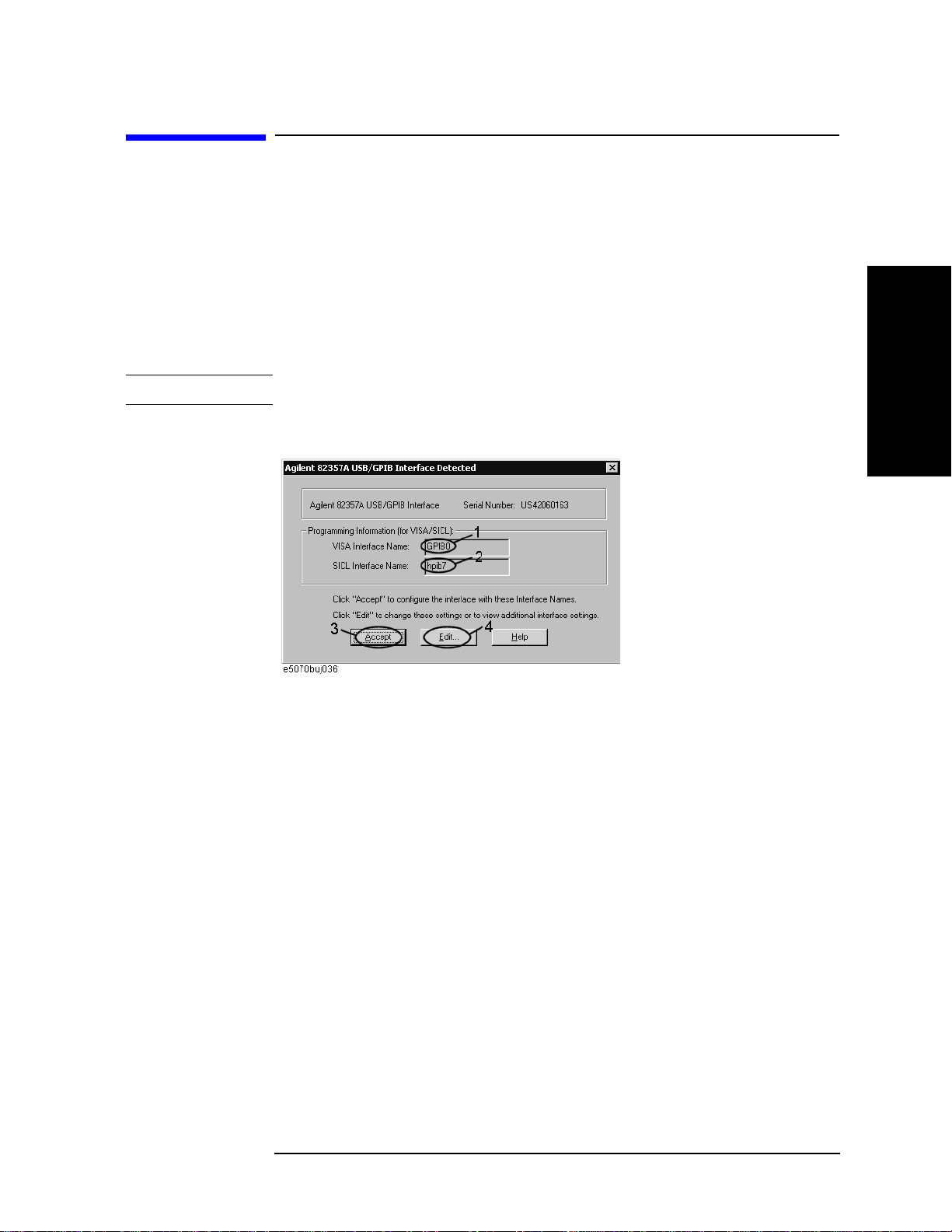
Step 1. Connect the USB port of the E5061A/E5062A to the USB/GPIB interface. The USB/GPIB
Interface Detected dialog box (
NOTE Do not connect two or more USB/GPIB interfaces.
Figure 2-1 USB/GPIB Interface Detected dialog box
Figure 2-1) appears.
Performance Tests
2. Performance Test
Step 2. Confirm that VISA Interface Name is set to GPIB0 (1 in Figure 2-1) and SICL Interface
Name is set to hpib7 (2 in Figure 2-1) and then click the Accept button (3 in Figure 2-1). If
the setting is correct, the procedure is complete. If the setting is different, click the Edit
button (4 in
Step 3. The USB to GPIB Configuration dialog box (Figure 2-2) appears. Make the setting
enclosed in the thick lines in Figure 2-2 (1 in Figure 2-2) according to the figure and then
click the OK button (2 in Figure 2-2).
Chapter 2 27
Figure 2-1).

Performance Tests
Instruction for Using the Performance Test Software
Figure 2-2 USB to GPIB Configuration dialog box
If you need to check/change the setting of the USB/GPIB interface after connecting the
USB/GPIB interface, follow these steps:
Step 1. Press .
Step 2. Press Misc Setup.
Step 3. Press GPIB Setup.
Step 4. Press System Controller Configuration.
Step 5. The IO Config dialog box (Figure 2-3) appears. Select (highlight) GPIB0 hpib7 (1 in
Figure 2-3) and then click the Edit button (2 in Figure 2-3).
NOTE In the IO Config dialog box, do not click buttons other than specified here or do not change
other settings because doing so may cause serious damage to the functions of the
E5061A/E5062A.
28 Chapter 2
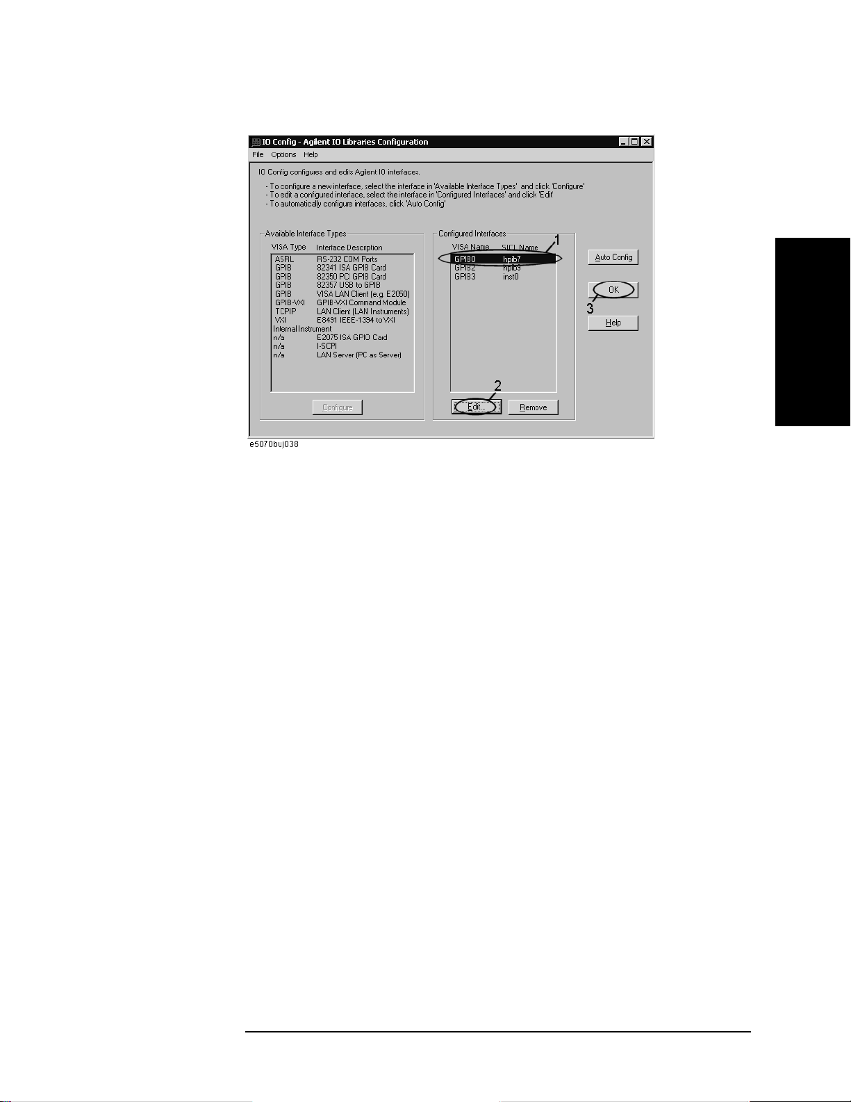
Figure 2-3 IO Config dialog box
Performance Tests
Instruction for Using the Performance Test Software
2. Performance Test
Step 6. The USB to GPIB Configuration dialog box (Figure 2-2) appears. Check/change the
setting of the USB/GPIB interface and then click the OK button (2 in Figure 2-2).
Step 7. In the USB to GPIB Configuration dialog box, click the OK button (3 in Figure 2-3).
Setting the GPIB address of the equipment
The test program needs the following GPIB address for the equipment.
• 53131A Frequency Counter --- 03
• E4419B Power Meter --- 13
• Z5623A Dynamic Accuracy Test Set --- 12
Setting up the E4419B Power Meter
You must set up the power meter before running the performance test program.
1. Connect the power sensor you use to the power meter’s channel.
• 8482A Power Sensor --- Connect to the channel A for testing the E5061A/E5062A
option 150/250
• 8483A Power Sensor --- Connect to the channel B for testing the E5061A/E5062A
option 175/275
2. Edit a Sensor Calibrattion Table for your power sensor. If you have already edited the
table for your power sensor, you can skip this step. Refer to the E4419B User’s Guide
for further information.
3. Select the Sensor Calibration Table for your power sensor. Refer to the E4419B User’s
Guide for further information.
4. Zero and calibrate the power meter. The reference calibration factor used during the
Chapter 2 29

Performance Tests
Instruction for Using the Performance Test Software
calibration is automatically set by the power meter from the sensor calibration table
you selected.
Running the Performance Tests
The program file name is “PerformanceTest.vba”. To perform the performance test for the
E5061A/E5062A, execute the program in accordance with the following procedure.
Step 1. Connect a mouse and an external keyboard to the E5061A/E5062A’s rear panel
connectors, then turn the E5061A/E5062A on.
Step 2. Insert the program disk.
Step 3. Press key.
Step 4. Press Load Project to select Load Project function. "Open" dialog box as shown below
appears.
Figure 2-4 Open dialog box
Step 5. Select "User [A]" from menu in the "Look in:" box.
Step 6. Click "PerformanceTest.vba" program file.
Step 7. Click "Open" button to download the test program.
Step 8. Press Select Macro to select Select Macro function.
Step 9. Press Module1 main to open the Module1 main program file. "E5061A/62A Performance
Test Program" dialog box (Main Menu) as shown below will appear.
Figure 2-5 Performance Test Program dialog box
30 Chapter 2
 Loading...