

Agilent
E4991A RF Impedance/Material Analyzer
Data Sheet

2
Definitions
All specifications apply over a 5 °C to 40 °C range
(unless otherwise stated) and 30 minutes after the
instrument has been turned on.
Specification (spec.)
Warranted performance. Specifications
include guardbands to account for the expected
statistical performance distribution, measurement
uncertainties, and changes in performance due
to environmental conditions.
Supplemental information is intended to provide
information useful in applying the instrument, but
that is not covered by the product warranty. The
information is denoted as typical, or nominal.
Typical (typ.)
Expected performance of an average unit which
does not include guardbands. It is not covered by
the product warranty.
Nominal (nom.)
A general, descriptive term that does not imply
a level of performance. It is not covered by the
product warranty.
Measurement Parameters and
Range
Measurement parameters
Impedance parameters:
|Z|, |Y|, Ls, Lp, Cs, Cp, Rs(R), Rp, X, G, B, D, Q, θz,
θy, |Γ|, Γx, Γy, θ
γ
Material parameters (option E4991A-002):
(see “Option E4991A-002 material measurement
(typical)” on page 17)
Permittivity parameters: |εr|, εr', εr", tanδ
Permeability parameters: |µr|, µr', µr", tanδ
Measurement range
Measurement range (|Z|):
130 mΩ to 20 kΩ.
(Frequency= 1 MHz,
Point averaging factor ≥ 8,
Oscillator level= –3 dBm; = –13 dBm; or = –23 dBm,
Measurement accuracy ≤ ±10%,
Calibration is performed within 23 °C ±5 °C,
Measurement is performed within ±5 °C of
calibration temperature)

3
1. It is possible to set more than 0 dBm (447 mV, 8.94 mA) oscillator
level at frequency > 1 GHz. However, the characteristics at this
setting are not guaranteed.
2. When the unit is set at mV or mA, the entered value is rounded
to 0.1 dB resolution.
DC Bias (Option E4991A-001)
DC voltage bias
Range:
0 to ±40 V
Resolution:
1 mV
Accuracy:
±{0.1% + 6 mV + (Idc[mA] x 20 Ω)[mV]}
(23 °C ±5 °C)
±{0.2% +12 mV + (Idc[mA] x 40 Ω)[mV]}
(5 °C to 40 °C)
DC current bias
Range:
100 µ A to 50 mA, –100 µ A to –50 mA
Resolution:
10 µ A
Accuracy:
±{0.2%+ 20 µ A+ (Vdc[V] /10 kΩ)[mA]}
(23 °C ±5 °C)
±{0.4% + 40 µ A+ (Vdc[V] /5 kΩ)[mA]}
(5 °C to 40 °C)
DC bias monitor
Monitor parameters:
Voltage and current
Voltage monitor accuracy:
±{0.5% + 15 mV + (Idc[mA] x 2 Ω)[mV]}
(23 °C ±5 °C, typical)
±{1.0% + 30 mV + (Idc[mA] x 4 Ω)[mV]}
(5 °C to 40 °C, typical)
Current monitor accuracy:
±{0.5% + 30 µ A + (Vdc[V] / 40 k Ω)[mA]}
(23 °C ±5 °C, typical)
±{1.0% + 60 µ A + (Vdc[V] / 20 k Ω)[mA]}
(5 °C to 40 °C, typical)
Source Characteristics
Frequency
Range:
1 MHz to 3 GHz
Resolution:
1 mHz
Accuracy:
without Option E4991A-1D5:
±10 ppm (23 °C ±5 °C)
±20 ppm (5 °C to 40 °C)
with Option E4991A-1D5:
±1 ppm (5 °C to 40 °C)
Stability:
with Option E4991A-1D5:
±0.5 ppm/year (5 °C to 40 °C)
Oscillator level
Range:
Power (when 50 Ω load is connected to test port):
–40 dBm to 1 dBm (frequency ≤ 1 GHz)
–40 dBm to 0 dBm (frequency > 1 GHz1)
Current (when short is connected to test port):
0.0894 mArms to 10 mArms (frequency ≤ 1 GHz)
0.0894 mArms to 8.94 mArms (frequency > 1 GHz1)
Voltage (when open is connected to test port):
4.47 mVrms to 502 mVrms (frequency ≤ 1 GHz)
4.47 mVrms to 447 mVrms (frequency > 1 GHz1)
Resolution:
0.1 dB
2
Accuracy:
(Power, when 50 Ω load is connected to test port)
Frequency ≤ 1 GHz:
±2 dB (23 °C ±5 °C)
±4 dB (5 °C to 40 °C)
Frequency > 1 GHz:
±3 dB (23 °C ±5 °C)
±5 dB (5 °C to 40 °C)
with Option E4991A-010:
Frequency ≤ 1 GHz
±3.5 dB (23 °C ± 5 °C)
±5.5 dB (5 °C to 40 °C)
Frequency > 1 GHz
±5.6 dB (23 °C ± 5 °C)
±7.6 dB (5 °C to 40 °C)
Output impedance
Output impedance:
50 Ω (nominal)

4
Measurement Accuracy
Conditions for defining accuracy
Temperature:
23 °C ±5 °C
Accuracy-specified plane:
7-mm connector of test head
Accuracy defined measurement points:
Same points at which the calibration is done.
Accuracy when open/short/load
calibration is performed
Probe Station Connection Kit
(Option E4991A-010)
Oscillator level
Power accuracy:
Frequency ≤ 1 GHz:
±5.5 dB (5 °C to 40 °C)
Frequency > 1 GHz:
±7.6 dB (5 °C to 40 °C)
Sweep Characteristics
Sweep conditions
Sweep parameters:
Frequency, oscillator level (power, voltage,
current), DC bias voltage, DC bias current
Sweep range setup:
Start/stop or center/span
Sweep types:
Frequency sweep: linear, log, segment
Other parameters sweep: linear, log
Sweep mode:
Continuous, single
Sweep directions:
Oscillator level, DC bias (voltage and current): up sweep,
down sweep
Other parameters sweep: up sweep
Number of measurement points:
2 to 801
Delay time:
Types: point delay, sweep delay, segment delay
Range: 0 to 30 sec
Resolution: 1 msec
Segment sweep
Available setup parameters for each segment:
Sweep frequency range, number of measurement
points, point averaging factor, oscillator level
(power, voltage, or current), DC bias (voltage or
current), DC bias limit (current limit for voltage
bias, voltage limit for current bias)
Number of segments:
1 to 16
Sweep span types:
Frequency base or order base
|Z|, |Y|: ±(Ea+ Eb) [%]
(see Figures 1 through 4
for examples of
calculated accuracy)
θ: ±
(Ea+ Eb)
[rad]
100
L, C, X, B: ±(E
a
+ Eb) x √(1 + D
2
x
) [%]
R, G: ±(Ea+ Eb) x √(1 + Q
2
x
) [%]
D:
at D
x
tan
E
a
+ E
b
< 1 ±
100
at D
x
≤0.1
±
E
a
+ E
b
100
Q:
at Qxtan
Ea+ E
b
< 1 ±
100
at
10
≥ Q
x
≥ 10 ±Q
2
x
Ea+ E
b
Ea+ E
b
100
(1 + D
2
x
)tan
Ea+ E
b
100
1 Dxtan
E
a
+ E
b
100
(1 + Q
2
x
)tan
E
a
+ E
b
100
1 Qxtan
E
a
+ E
b
100
±
±

at Oscillator level < –33 dBm:
±1 [%] (1 MHz ≤ Frequency ≤ 100 MHz)
±1.2 [%] (100 MHz < Frequency ≤ 500 MHz)
±1.2 [%] (500 MHz < Frequency ≤ 1 GHz)
±2.5 [%] (1 GHz < Frequency ≤ 1.8 GHz)
±5 [%] (1.8 GHz < Frequency ≤ 3 GHz)
Eb =
(|Zx|: measurement value of |Z|)
Ec =
(F: frequency [MHz], typical)
Zs = (Within ±5 °C from the calibration temperature.
Measurement accuracy applies when the calibration
is performed at 23 °C ±5 °C. When the calibration
is performed beyond 23 °C ±5 °C, the measurement
accuracy decreases to half that described.
F: frequency [MHz].)
at oscillator level = –3 dBm, –13 dBm, or –23 dBm:
±(13 + 0.5 × F) [mΩ] (averaging factor ≥ 8)
±(25 + 0.5 × F) [mΩ] (averaging factor ≤ 7)
at oscillator level ≥ –33 dBm
±(25 + 0.5 × F) [mΩ] (averaging factor ≥ 8)
±(50 + 0.5 × F) [mΩ] (averaging factor ≤ 7)
at oscillator level < –33 dBm
±(50 + 0.5 × F) [mΩ] (averaging factor ≥ 8)
±(100 + 0.5 × F) [mΩ] (averaging factor ≤ 7)
Yo = (Within ±5 °C from the calibration temperature.
Measurement accuracy applies when the calibration
is performed at 23 °C ±5 °C. When the calibration
is performed beyond 23 °C ±5 °C, the measurement
accuracy decreases to half that described.
F: frequency [MHz].)
at oscillator level = –3 dBm, –13 dBm, –23 dBm:
±(5 + 0.1 × F) [µS] (averaging factor ≥ 8)
±(10 + 0.1 × F) [µS] (averaging factor ≤ 7)
at oscillator level ≥ –33 dBm:
±(10 + 0.1 × F) [µS] (averaging factor ≥ 8)
±(30 + 0.1 × F) [µS] (averaging factor ≤ 7)
at oscillator level < –33 dBm
±(20 + 0.1 × F) [µS] (averaging factor ≥ 8)
±(60 + 0.1 × F) [µS] (averaging factor ≤ 7)
± 0.06 +
0.08 × F
[%]
1000
Accuracy when open/short/load/low-loss
capacitor calibration is performed
(See Figure 5)
Definition of each parameter
Dx = Measurement value of D
Qx = Measurement value of Q
Ea = (Within ±5 °C from the calibration temperature.
Measurement accuracy applies when the calibration
is performed at 23 °C ±5 °C. When the calibration
is performed beyond 23 °C ±5 °C, measurement
error doubles.)
at oscillator level ≥ –33 dBm:
±0.65 [%] (1 MHz ≤ Frequency ≤ 100 MHz)
±0.8 [%] (100 MHz < Frequency ≤ 500 MHz)
±1.2 [%] (500 MHz < Frequency ≤ 1 GHz)
±2.5 [%] (1 GHz < Frequency ≤ 1.8 GHz)
±5 [%] (1.8 GHz < Frequency ≤ 3 GHz)
|Z|, |Y|: ±(Ea+ Eb) [%]
θ: ±
E
c
[rad]
100
L, C, X, B: ± √(E
a
+ Eb)2+ (EcDx)2[%]
R, G: ± √(Ea+ Eb)2+ (EcQx)2[%]
D:
at Dxtan
E
c
< 1 ±
100
at D
x
≤0.1 ±
E
c
100
Q:
at Qxtan
E
c
< 1 ±
100
at
10
≥Qx≥ 10 ±Q
2
x
E
c
E
c
100
(1 + D
2
x
)tan
E
c
100
1 Dxtan
E
c
100
(1 + Q
2
x
)tan
E
c
100
1 Qxtan
E
c
100
±
Z
s
+Yo• Zx× 100 [%]
Z
x
5
±
±

6
Figure 2. |Z|, |Y| Measurement accuracy when open/short/load
calibration is performed. Oscillator level ≥ –33 dBm.
Point averaging factor ≥ 8 within ±5 °C from the calibration
temperature.
Figure 3. |Z|, |Y| Measurement accuracy when open/short/load
calibration is performed. Oscillator level ≥ –33 dBm.
Point averaging factor ≤ 7 within ±5 °C from the calibration
temperature.
Measurement Accuracy
(continued)
Examples of calculated impedance
measurement accuracy
Figure 1. |Z|, |Y| Measurement accuracy when open/short/load
calibration is performed. Oscillator level = –23 dBm,
–13 dBm, –3 dBm. Point averaging factor ≥ 8 within ±5 °C
from the calibration temperature.

7
Figure 4. |Z|, |Y| Measurement accuracy when open/short/load
calibration is performed. Oscillator level < –33 dBm within
±5 °C from the calibration temperature.
Figure 5. Q Measurement accuracy when open/short/load/low-loss
capacitor calibration is performed (typical).
Measurement Support
Functions
Error correction
Available calibration and compensation
Open/short/load calibration:
Connect open, short, and load standards to the
desired reference plane and measure each kind
of calibration data. The reference plane is called
the calibration reference plane.
Low-loss capacitor calibration:
Connect the dedicated standard (low-loss
capacitor) to the calibration reference plane
and measure the calibration data.
Port extension compensation (fixture selection):
When a device is connected to a terminal that is
extended from the calibration reference plane,
set the electrical length between the calibration
plane and the device contact. Select the model
number of the registered test fixtures in the
E4991A’s setup toolbar or enter the electrical
length for the user’s test fixture.
Open/short compensation:
When a device is connected to a terminal that
is extended from the calibration reference
plane, make open and/or short states at the
device contact and measure each kind of
compensation data.
Calibration/compensation data measurement point
User-defined point mode:
Obtain calibration/compensation data at
the same frequency and power points as used
in actual device measurement, which are
determined by the sweep setups. Each set of
calibration/compensation data is applied to each
measurement at the same point. If measurement
points (frequency and/or power) are changed
by altering the sweep setups, calibration/
compensation data become invalid and calibration
or compensation data acquisition is again required.

8
Measurement Support
Functions
(continued)
Fixed frequency and fixed power point mode:
Obtain calibration/compensation data at fixed
frequency and power points covering the entire
frequency and power range of the E4991A. In
device measurement, calibration or compensation
is applied to each measurement point by using
interpolation. Even if the measurement points
(frequency and/or power) are changed by
altering the sweep setups, you don’t need to
retake the calibration or compensation data.
Fixed frequency and user-defined power point mode:
Obtain calibration/compensation data at fixed
frequency points covering the entire frequency
range of the E4991A and at the same power
points as used in actual device measurement
which are determined by the sweep setups.
Only if the power points are changed, calibration/
compensation data become invalid and
calibration or compensation data acquisition
is again required.
Trigger
Trigger mode:
Internal, external (external trigger input
connector), bus (GPIB), manual (front key)
Averaging
Types:
Sweep-to-sweep averaging, point averaging
Setting range:
Sweep-to-sweep averaging: 1 to 999 (integer)
Point averaging: 1 to 100 (integer)
Display
LCD display :
Type/size: color LCD, 8.4 inch (21.3 cm)
Resolution: 640 (horizontal) × 480 (vertical)
Number of traces:
Data trace: 3 scalar traces + 2 complex traces
(maximum)
Memory trace: 3 scalar traces + 2 complex traces
(maximum)
Trace data math:
Data – memory, data/memory (for complex
parameters), delta% (for scalar parameters), offset
Format:
For scalar parameters: linear Y-axis, log Y-axis
For complex parameters: Z, Y: polar, complex; Γ: polar,
complex, Smith, admittance
Other display functions:
Split/overlay display (for scalar parameters),
phase expansion
Marker

9
3. Refer to the standard for the meaning of each function code.
Number of markers:
Main marker: one for each trace (marker 1)
Sub marker: seven for each trace (marker 2 to
marker 8)
Reference marker: one for each trace (marker R)
Marker search:
Search type: maximum, minimum, target, peak
Search track: performs search with each sweep
Other functions:
Marker continuous mode, marker coupled mode,
marker list, marker statistics
Equivalent circuit analysis
Circuit models:
3-component model (4 models),
4-component model (1 model)
Analysis types:
Equivalent circuit parameters calculation,
frequency characteristics simulation
Limit marker test
Number of markers for limit test:
9 (marker R, marker 1 to 8)
Setup parameters for each marker:
Stimulus value, upper limit, and lower limit
Mass storage
Built-in flexible disk drive:
3.5 inch, 720 KByte or 1.44 MByte, DOS format
Hard disk drive:
2 GByte (minimum)
Stored data:
State (binary), measurement data (binary, ASCII
or CITI file), display graphics (bmp, jpg), VBA
program (binary)
Interface
GPIB
Standard conformity:
IEEE 488.1-1987, IEEE 488.2-1987
Available functions (function code)3:
SH1, AH1, T6, TE0, L4, LE0, SR1, RL0, PP0, DT1,
DC1, C0, E2
Numerical data transfer format:
ASCII
Protocol:
IEEE 488.2-1987
Printer parallel port
Interface standard:
IEEE 1284 Centronics
Connector type:
25-pin D-sub connector, female
LAN interface
Standard conformity:
10 Base-T or 100 Base-TX (automatically
switched), Ethertwist, RJ45 connector
Protocol:
TCP/IP
Functions:
FTP

10
Rear panel connectors
External reference signal input connector
Frequency:
10 MHz ±10 ppm (typical)
Level:
0 dBm to +6 dBm (typical)
Input impedance:
50 Ω (nominal)
Connector type:
BNC, female
Internal reference signal output connector
Frequency:
10 MHz (nominal)
Accuracy of frequency:
Same as frequency accuracy described in
“Frequency” on page 3
Level:
+2 dBm (nominal)
Output impedance:
50 Ω (nominal)
Connector type:
BNC, female
High stability frequency reference
output connector (Option E4991A-1D5)
Frequency:
10 MHz (nominal)
Accuracy of frequency:
Same as frequency accuracy described in
“Frequency” on page 3
Level:
+2 dBm (nominal)
Output impedance:
50 Ω (nominal)
Connector type:
BNC, female
Measurement Terminal
(At Test Head)
Connector type:
7-mm connector
11
General Characteristics
Environment conditions
Operating condition
Temperature:
5 °C to 40 °C
Humidity:
(at wet bulb temperature ≤ 29 °C,
without condensation)
Flexible disk drive non-operating condition:
15% to 90% RH
Flexible disk drive operating condition:
20% to 80% RH
Altitude:
0 m to 2,000 m (0 feet to 6,561 feet)
Vibration:
0.5 G maximum, 5 Hz to 500 Hz
Warm-up time:
30 minutes
Non-operating storage condition
Temperature:
–20 °C to +60 °C
Humidity:
(at wet bulb temperature ≤ 45 °C,
without condensation)
15% to 90% RH
Altitude:
0 m to 4,572 m (0 feet to 15,000 feet)
Vibration:
1 G maximum, 5 Hz to 500 Hz
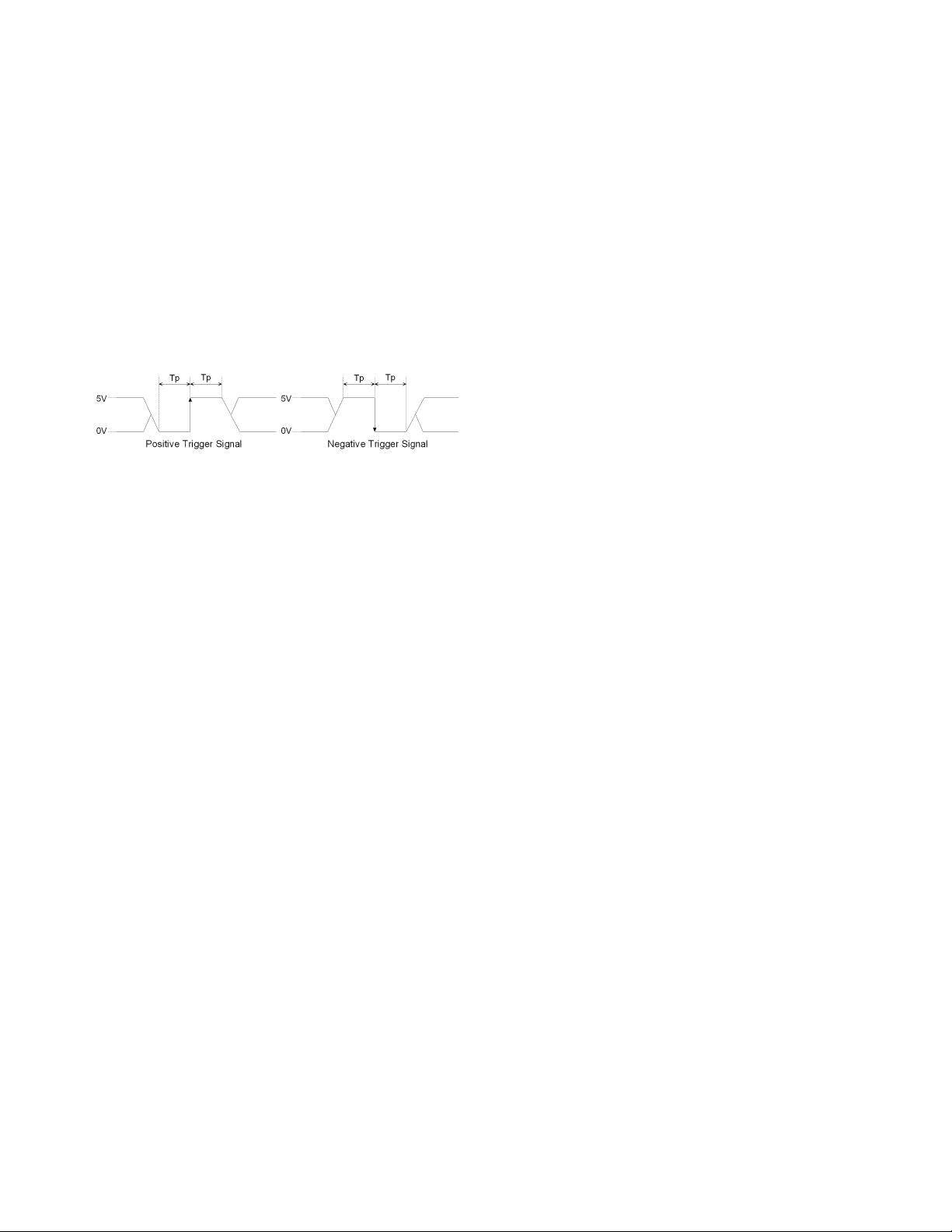
External trigger input connector
Level:
LOW threshold voltage: 0.5 V
HIGH threshold voltage: 2.1 V
Input level range: 0 V to +5 V
Pulse width (Tp):
≥ 2 µ sec (typical). See Figure 6 for definition of Tp.
Polarity:
Positive or negative (selective)
Connector type:
BNC, female
Figure 6. Definition of pulse width (Tp)
12
General Characteristics
(continued)
Other specifications
EMC
European Council Directive 89/336/EEC
IEC 61326-1:1997+A1
CISPR 11:1990 / EN 55011:1991 Group 1, Class A
IEC 61000-4-2:1995 / EN 61000-4-2:1995
4 kV CD / 4 kV AD
IEC 61000-4-3:1995 / EN 61000-4-3:1996
3 V/m, 80-1000 MHz, 80% AM
IEC 61000-4-4:1995 / EN 61000-4-4:1995
1 kV power / 0.5 kV Signal
IEC 61000-4-5:1995 / EN 61000-4-5:1995
0.5 kV Normal / 1 kV Common
IEC 61000-4-6:1996 / EN 61000-4-6:1996
3 V, 0.15-80 MHz, 80% AM
IEC 61000-4-11:1994 / EN 61000-4-11:1994
100% 1cycle
Note: When tested at 3 V/m according to
EN 61000-4-3:1996, the measurement accuracy
will be within specifications over the full immunity
test frequency range of 80 MHz to 1000 MHz except
when the analyzer frequency is identical to the
transmitted interference signal test frequency.
AS/NZS 2064.1/2 Group 1, Class A
Safety
European Council Directive 73/23/EEC
IEC 61010-1:1990+A1+A2 / EN 61010-1:1993+A2
INSTALLATION CATEGORY II, POLLUTION
DEGREE 2
INDOOR USE
IEC60825-1:1994 CLASS 1 LED PRODUCT
CAN/CSA C22.2 No. 1010.1-92
Power requirements
90 V to 132 V, or 198 V to 264 V (automatically
switched), 47 Hz to 63 Hz, 350 VA maximum
Weight
Main unit: 17 kg (nominal)
Test head: 1 kg (nominal)
Dimensions
Main unit: See Figure 7 through Figure 9
Test head: See Figure 10
Option E4991A-007 test head dimensions: See Figure 11
Option E4991A-010 test head dimensions: See Figure 12
 Loading...