


User’ s Guide
Agilent Technologies
E4418B Power Meter
Agilent Technologies Part no. E4418-90032
December, 1998

© Copyright 1998 Agilent Technologies
All rights reserved. Reproduction, adaptation, or translation without prior
written permission is prohibited, except as allowed under the copyright
laws.
Printed in the UK.
ii Agilent E4418B User’s Guide

Legal Information
Legal Information
Notice
Information contained in this document is subject to change without
notice. Agilent T echno logies makes no warranty of any kind with regard to
this material, including, but not limited to, the implied warranties of
merchantability and fitness for a particular purpose. Agilent Technologies
shall not be liable for errors contained herein or for incidental or
consequential damages in connection with the furnishings, performance,
or use of this material. No part of t h is document may be photocopied,
reproduced, or translated to another language without the prior written
consent of Agilent Technologies.
Certification
Agilent Technologies certifies that this product met its published
specifications at the time of shipment from the factory. Agilent
Technologies further certifies that its calibration measurements are
traceable to the United States National Institute of Standards and
T echnology, to the extent allowed by the Institute’s calibration facility, and
to the calibration facilities of other International Standards Organization
members.
Warranty
This Agilent Technologies instrument product is warranted against
defects in material and workmanship for a period of one year from date of
shipment. During the warranty period, Agilent Technologies will at its
option, either repair or replace products which prove to be defective. For
warranty service or repair, this product must be returned to a service
facility designated by Agilent Technologies. Buyer shall prepay shipping
charges to Agilent Technologies and Agilent Technologies shall pay
shipping charges, duties, and taxes for products returned to Aglent
Technologies from another country. Agilent T ech nologies warra nts that its
software and firmware design ated by Agilent Technologies for use with an
instrument will execute its programming instructions when properly
installed on that instrument. Agilent Technologies does not warrant that
the operation of the instrument, or firmware will be uninterrupted or
error free.
Agilent E4418B User’s Guide iii

Legal Information
Limitation of Warranty
The foregoing warranty shall not apply to defects resulting from improper
or inadequate maintenance by Buyer, Buyer-supplied software or
interfacing, unauthorized modificatio n or misuse , operatio n outsi de of the
environmental specifications for the product, or improper site preparation
or maintenance. NO OTHER W ARRANTY IS EXPRESSED OR IMPLIED.
HP SPECIFICALLY DISCLAIMS THE IMPLIED WARRANTIES OF
MERCHANTABILITY AND FITNESS FOR A PARTICULAR PURPOSE.
Exclusive Remedies
THE REMEDIES PROVIDED HEREIN ARE BUYER’S SOLE AND
EXCLUSIVE REMEDIES. AGILENT TECHNOLOGIES SHALL NOT BE
LIABLE FOR ANY DIRECT, INDIRECT, SPECIAL, INCIDENTAL, OR
CONSEQUENTIAL DAMAGES, WHETHER BASED ON CONTRACT,
TORT, OR ANY OTHER LEGAL THEORY.
iv Agilent E4418B User’s Guide

Equipment Operation
Equipment Operation
Warnings and Cautions
This guide uses warnings and cautions to denote hazards.
WARNING A warning calls attention to a procedure, practice or the
like, which, if not correctly performed or adhered to, c ould
result in injury or the loss of life. Do not proceed beyond a
warning until the indicated conditions are fully
understood and met.
Caution A caution calls attention to a procedure, practice or the like which,
if not correctly performed or adhered to, could result in damage to
or the destruction of part or all of the equipment. Do not proceed
beyond a caution until the indicated conditions are fully
understood and met.
Personal Safety Considerations
WARNING This is a Safety Class I pro duct (provided with a p rotecti ve
earthing ground incorporated in the power cord). The
mains plug shall only be inserted in a socket outlet
provided with a protective earth contact. Any interruption
of the protective conductor, inside or outside the
instrument, is likely to make the instrument dangerous.
Intentional interruption is prohibited.
If this instrument is not used as specified, the prot ection
provided by the equipment could be impair ed. This
instrument must be used in a normal condition (in which
all means of protection are intact) only.
No operator serviceable parts inside. Refer servicing t o
qualified personnel. To prevent electrical shock, do not
remove covers.
For continued protection against fire hazard, replace the
line fuse(s) only with fuses of the same t y pe a n d r ating (for
example, normal blow, time delay, etc. ) . The use of other
fuses or material is prohibited.
Agilent E4418B User’s Guide v

General Safety Considerations
ISM
GROUP 1
CLASS A
General Safety Considerations
WARNING Before this instrument is switched on, make sure it has
been properly grounded through the protective conductor
of the ac power cable to a socket outlet p rovided with
protective earth contact.
Any interruption of the protective (grounding) conductor,
inside or outside the instrument, or disconnection of the
protective earth terminal can result in personal injury.
Caution Any adjustments or service procedures that require operation of
the instrument with protective covers removed should be
performed only by trained service pers onnel.
Markings
The CE mark shows that the product complies with
all the relevant European legal Directives (if
accompanied by a year, it signifies when the design
was proven.
This is the symbol of an Industrial Scientific and
Medical Group 1 Class A product.
The CSA mark is a registered trademark of the
Canadian Standards Association.
External Protective Earth Terminal.
While this is a Class I product, provided with a
protective earthing conductor in a power cord, an
external protective earthing terminal has also been
provided. This termin al is fo r us e wh ere the ea rthin g
cannot be assured. At least an 18AWG earthing
conductor should be used in such an instance, to
ground the instrument to an assured earth terminal.
vi Agilent E4418B User’s Guide

General Safety Considerations
IEC 1010-1 Compliance
This instrument has been designed and tested in accordance with IEC
Publication 61010-1 +A1:1992 Safety Requirements for Electrical
Equipment for Measurement, Control and Laboratory Use and has been
supplied in a safe condition. The instruction documentation contains
information and warnings which must be followed by the user to ensure
safe operation and to maintain the instrument in a safe condition.
Statement of Compli ance
This product has been designed and tested for compliance with IEC 60529
(1989) Degrees of Protection Provided by Enclosures (IP Code). Level IPx4
is attained if, and only if, the carry case( Agilent Technologies part
number 34141A) is fitted.
User Environment
This product is designed for use in a sheltered environment (avoiding
extreme weather conditions) in accordance with Pollution Degree 3
defined in IEC 60664-1, with the carry case (Agilent Technologies part
number 34141A) fitted over the instrument.
The product is suitable for indoor use only, when this carry case is not
fitted.
Installation Instructions
T o a void unnecessary over-t emperature conditi ons, while this carry case is
fitted do not apply an ac mains supply voltage, only operate your Agilent
Technologies E4418B from the battery pack.
Agilent E4418B User’s Guide vii

Regulatory Information
Regulatory Information
Sound Emission
Herstellerbescheinigung
Diese Information steht im Zusammenhang mit den Anforderungen der
Maschinenlarminformationsverordnung vom 18 Januar 1991.
• Sound Pressure LpA < 70 dB.
• Am Arbeitsplatz.
• Normaler Betrieb.
• Nach DIN 45635 T. 19 (Typprufung).
Manufacturers Declaration
This statement is provided to comply with the requirements of the
German Sound DIN 45635 T. 19 (Typprufung).
• Sound Pressure LpA < 70 dB.
• At operator position.
• Normal operation.
• According to ISO 7779 (Type Test).
Australian EMC Regulations
N279
The C-Tick mark is a registered trademark of the Spectrum Management
Agency of Australia. This signifies compliance with the Australian EMC
Framework Regulations under the terms of the Radiocommunications Act
of 1992.
viii Agilent E4418B User’s Guide

Regulatory Information
Declaration of Conformity
according to ISO/IE C Guide 22 and EN45014
Manufacturer’s Name: Agilent Technologies
Manufacturer's Address:
Declares that the product
Product Name
:
Model Numbers:
Product Options:
Conforms with the prot e ct ion requirements of European Council Direc ti ve 89/336/EEC on the approximation
of the laws of the member states relating to electromagnetic compatib ility.
Against EMC test specifications EN 55011:1991 (Group 1, Class A) and EN 50082-1:1992
As Detailed in:
Assessed by:
Technical Report Number:6893/2200/CBR, dated 23 September 1997
Supplementary Information: The product conf orms to the following safety standa rds
The product herewit h com plies with the requi re ments of the Low Voltage D ire c ti ve 73/23/EEC, and carries the
CE-marking accordingly. This product is also designed to meet IPx4 in accordanc e with IEC 60529:1989 / EN
60529:1992.
South Queensferry, Scotland 22 October 1998
South Queensferry
West Lothian, EH30 9TG
Scotland, United Kingdom
Single Channel Power Meter
Agilent E4418B
This declaration covers al l opt ions of the above products as de t ai le d in
TCF A-5951-9852-02
Electromagnetic Compatibility (EMC)
Technical Construction File (TCF) N o. A-5951-9852-01
Dti Appointed Competent Body
EMC Test Centre,
GEC-Marconi Avionics Ltd.,
Maxwell Building,
Donibristle Industrial Park,
KY11 5LB
Scotland, United Kingdom
EN61010-1 (1993) / IEC 1010-1 (1990) + A1 (1992)
CSA-C22.2 No. 1010.1-92
EN60825-1 (1994) / IEC 825-1 (1993)
Location Date
Europe Contact:
Your local Agilent Technologies Sales and Service Office or Agilent Technologies GmbH, Department 2Q /
Standards Europe, Herrenberger Strasse 130, D7030 Boblinger (Fax; +49-7031-143143).
R.M. Evans / Quality Manager
Agilent E4418B User’s Guide ix

List of Related Publications
List of Related Publications
The Agilent E4418B is also available in the following languages:
• English La ng u a g e Use r’s Guide - Standard
• German Language User’s Guide - Option ABD
• Spanish Language User’s Guide - Option ABE
• French Language User’s Guide - Option ABF
• Italian Language User’s Guide - Option ABZ
• Japanese Language User’s Guide - Option ABJ
Agilent Technologies E4418B/E4419B Programming Guide is shipped as
standard.
Agilent Technologies E4418B/E4419B Service Guide is available by
ordering Option 915.
Agilent Technologies E4418B/E4419B CLIPs (Component Location and
Information Pack) is available by ordering E4418-90031.
Useful information on SCPI (Standard Commands for Programmable
Instruments) can be found in:
• A Beginner’s Guide to SCPI, which is available by ordering Agilent
Technologies Part Number 5010-7166.
• The SCPI reference manuals which are available from:
SCPI Consortium,
8380 Hercules Drive, Suite P3,
La Mesa, CA 91942, USA.
Telephone: 619-697-4301
Fax: 619-697-5955
x A gilent E4418B User’s Guide

Agilent Technologies E4418B Options
Agilent Technologies E4418B Options
The Agilent E4418B power meters have the following options available:
• Option 001, supplies an internal rechargeable battery providing
full instrument functionality when access to an ac power outlet is
not available.
• Option 002, supplies parallel rear panel sensor input(s). The
power reference oscillator output is on the front panel.
• Option 003, supplies parallel rear panel sensor input(s). The
power reference oscillator output is also on the rear panel.
• Option 004, deletes the Agilent 11730A sensor cable(s) provided.
• Option 0BO, deletes manual set.
• Option 908, provides rackmount kit for one instrument.
• Option 909, provides rackmount kit for two instruments.
• Option 915, provides the Agilent E4418B/E4419B Service Guide.
• Option 916, provides an additional Agilent E4418B User’s Guide
and Agilent E4418B/E4419B Programming Guide.
• Option 1BN, provides MIL-STD 45662A, Certificate of
Calibration.
• Option 1BP, provides MIL-STD-45662A, Certificate of Calibration
and data.
Available Accessories
• Agilent 34161A Accessory Pouch
• Agilent 34141A Yellow soft carry/operating case
• Agilent 34131A basic instrument transit case
• Agilent E9287A Spare battery pack - for instruments fitted with
option 001 only
• Agilent 34397A 12 Vdc to 115 Vac inverter (Option 0E3 230 V)
• The following Ag ilent power sensor cables are available:
■ Agilent 11730A 1.5 m (7.5 ft)
■ Agilent 11730B 3 m (10 ft)
■ Agilent 11730C 6.1 m (20 ft)
■ Agilent 11730D 15.2 m (50 ft)
■ Agilent 11730E 30.5 m (100 ft)
■ Agilent 11730F 61 m (200 ft)
Agilent E4418B User’s Guide xi

About this Guide
About this Guide
Chapter 1: Getting Started
This chapter prepares the power meter for use and helps you to get
familiar with a few of the front panel features.
Chapter 2: Power Meter Operation
This chapter gives a detailed description of the capabilities and operation
of the power meter. You will find this chapter useful when you are
operating the power meter from the front panel.
Chapter 3: Menu Map Reference
This chapter details diagrammatically the menu maps for the power
meter. It also gives a description of all the power meter’s keys.
Chapter 4: Error Messages
This chapter lists the error messages that may appear as you are working
with the power meter. Each description contains information to help you
diagnose and solve the problem.
Chapter 5: Specifications
This chapter lists the power meter’s specifications and describes how to
interpret these specifications.
xii Agilent E4418B User’s Guide

Table of Contents
Legal Information ........................................................................iii
Notice .....................................................................................iii
Certification...........................................................................iii
Warranty................................................................................iii
Limitation of Warranty......................................................... iv
Exclusive Remedies............................................................... iv
Equipment Operation ................................................................... v
Personal Safety Considerations............................................. v
General Safety Considerations.................................................... vi
Markings................................................................................ vi
IEC 1010-1 Compliance........................................................ vii
Statement of Compliance..................................................... vii
User Environment................................................................ vii
Installation Instructions ...................................................... vii
Regulatory Information .............................................................viii
Sound Emission................................................................... viii
Australian EMC Regulations.............................................. viii
List of Related Publications ......................................................... x
Agilent Technologies E4418B Options........................................ xi
Available Accessories ............................................................ xi
About this Guide ......................................................................... xii
Page
Getting Started.................................................................................... 1-1
Introduction................................................................................... 1-2
Turning On the Power Meter....................................................... 1-3
The Front Panel at a Glance ........................................................ 1-4
The Display Layout....................................................................... 1-7
Selecting Your Display Layout.............................................. 1-11
Window Symbols........................................................................... 1-14
Warning Symbol..................................................................... 1-14
Confirmation Window ............................................................ 1-14
Wait Symbol...... ....... ...... ....... ...... ...... ....... ...... ....... ...... ....... ..... 1-14
1 of N Entry Window.............................................................. 1-15
Numeric or Alphanumeric Entry Window... ....... ...... ....... ..... 1-15
Agilent E4418B User’s Guide Contents-1

The Rear Panel at a Glance.......................................................... 1-16
Adjusting the Carrying Handle.................................................... 1-18
Rack Mounting the Power Meter ................................................. 1-19
Power Meter Operation..................................................................... 2-1
Introduction................................................................................... 2-2
Battery Operation (Option 001) ................................................... 2-3
General Information............................................................... 2-3
Running Time... ....... ...... ....... ...... ....... ...... ...... ....... ...... ....... ..... 2-3
Charging Times ...................................................................... 2-4
Backlight................................................................................. 2-4
Battery Removal/Replacement .................................. ....... ..... 2-5
Zeroing and Calibrating the Power Meter................................... 2-7
Zeroing the Power Meter........................................................ 2-7
Zero/Cal Lockout..................................................................... 2-7
Calibrating the Power Meter................................................. 2-8
Calibration Procedure Us ing Agilent E-Series
Power Sensors.......... ...... ....... ...... ....... ...... ...... ....... ...... ............ 2-8
Calibration Procedure using Agilent 8480 Series
Power Sensors.......... ...... ....... ...... ....... ...... ...... ....... ...... ............ 2-9
Zeroing and Calibrating Using TTL Inputs.......................... 2-12
Making Measurements with the Agilent E-Series
Power Sensors................................................ ...... ....... ...... ....... ..... 2-15
Procedure................................................................................ 2-15
Making Measurements with the Agilent 8480 Series
Power Sensors................................................ ...... ....... ...... ....... ..... 2-17
Procedure................................................................................ 2-17
Making Measurements using Sensor Calibration Tables .......... 2-19
Selecting a Sensor Calibration Table.................................... 2-19
Making the Measurement...................................................... 2-20
Editing Sensor Calibration Tables ........................................ 2-21
Making Measurements using Frequency Dependent
Offset Tables ................................................................................. 2-27
Selecting a Frequency Dependent Offset Table.................... 2-27
Making the Measurement...................................................... 2-28
Editing Frequency Dependent Offset Tables........................ 2-29
Setting the Units of Measurement............................................... 2-32
Selecting Units of Measurement from the Softkeys ................... 2-33
Making Relative Measurements.................................................. 2-34
Procedure................................................................................ 2-34
Setting the Resolution .................................................................. 2-35
Setting Offsets............................................................................... 2-36
Setting Channel Offsets......................................................... 2-36
Contents-2 Agilent E4418B User’s Guide

Setting Display Offsets .......................................................... 2-36
Setting Averaging ......................................................................... 2-38
Step Detection......................................................................... 2-39
Measuring Pulsed Signals............................................................ 2-41
Setting Measurement Limits ....................................................... 2-43
Setting Channel Limits.......................................................... 2-43
Setting Window Limits .......................................................... 2-44
Checking for Limit Failures................................................... 2-47
Selecting a Digital or Analog Display.......................................... 2-49
Setting the Range ......................................................................... 2-52
Configuring the Remote Interface................................................ 2-53
GP-IB....................................................................................... 2-53
RS232/RS422 .......................................................................... 2-54
Remote Interface Overview.................................................... 2-56
Programming Language Selection ........................................ 2-58
Recorder Output............................................................................ 2-59
Leveling a Source Output ...................................................... 2-60
Saving and Recalling Power Meter Configurations.................... 2-61
How Measurements are Calculated............................................. 2-63
Presetting the Power Meter ......................................................... 2-64
Preset Conditions ................................................................... 2-64
Self Test......................................................................................... 2-66
Power On Self Test................................................................. 2-66
Front Panel Selection of Self Tests........................................ 2-67
Remote Testing....................................................................... 2-69
Test Descriptions.................................................................... 2-70
Operator Maintenance...................... ...... ....... ............................... 2-73
Replacing the Power Line Fuse ............................................. 2-73
Contacting Agilent Technologies............ ....... ............................... 2- 74
Before calling Agilent Technologies ...................................... 2-74
Check the Basics..................................................................... 2-75
Instrument serial numbers.................................. ...... ....... ..... 2-75
Sales and Service Offices ....................................................... 2-77
Returning Your Power Meter for Service.............................. 2-79
Menu Reference................................................................................... 3-1
Introduction................................................................................... 3-2
The Front Panel Menu Maps ....................................................... 3-3
dBm/W Menu.......................................................................... 3-3
Frequency/Cal Fac Menu ....................................................... 3-4
Meas Setup Menu................................................................... 3-5
Rel/Offset Menu...................................................................... 3-6
Save/Recall Menu ................................................................... 3-6
Agilent E4418B User’s Guide Contents-3

System Inputs Menu (1 of 4).................................................. 3-7
System Inputs Menu (2 of 4).................................................. 3-8
System Inputs Menu (3 of 4).................................................. 3-9
System Inputs Menu (4 of 4).................................................. 3-10
Zero/Cal Menu ........................................................................ 3-11
Front Panel Menu Reference........................................................ 3-12
Diagrammatical Hardkeys .................................................... 3-36
Error Messages .................................................................................... 4-1
Introduction................................................................................... 4-2
Error Messages ............................................................................. 4-4
Specifications....................................................................................... 5-1
Introduction................................................................................... 5-2
Power Meter Specifications..................................................... ..... 5-3
Meter....................................................................................... 5-3
Accuracy.................................................................................. 5-4
Power Reference......................................................... ....... ..... 5-5
Power Meter Supplemental Characteristics ............................... 5-6
Power Reference......................................................... ....... ..... 5-6
Measurement Speed.......................... ...... ...... ....... ...... ............ 5-6
Zero Drift of Sensors .............................................................. 5-7
Measurement Noise. ...... ....................................... ...... ....... ..... 5-7
Settling Time .......................................................................... 5-9
Power Sensor Specifications .................................................. 5-12
Battery Option 001 Operational Characteristics ........................ 5-13
General Characteristics................................................................ 5-14
Rear Panel Connectors........................................................... 5-14
Environmental Characteristics.................................................... 5-15
General Conditions................................................................. 5-15
Operating Environment......................................................... 5-15
Storage Conditions ................................................................. 5-15
General.......................................................................................... 5-16
Dimensions ............................................................................. 5-16
Weight..................................................................................... 5-16
Safety ...................................................................................... 5-16
Remote Programming ............................................................ 5-16
Non-Volatile Memory ............................................................. 5-17
Contents-4 Agilent E4418B User’s Guide

List of Figures
Page
2-1 Battery Status............. ...... ....................................... ...... ....... ..... 2-4
2-2 Battery Removal/Replacement ................................................. 2-6
2-3 Rmt I/O Port TTL Inputs .................... ....... ...... ....... ...... ....... ..... 2-12
2-4 “Sensor Tbls” Screen.................................................................. 2-20
2-5 “Edit Cal” Screen ....................................................................... 2-21
2-6 “Offset Tbls” Screen................................................................... 2-28
2-7 “Edit” Screen.............................................................................. 2-29
2-8 Effect of Offsets on a Channel Measurement........................... 2-37
2-9 Averaged Readings .................................................................... 2-39
2-10 Pulsed Signal ............................................................................. 2-41
2-11 Limits Checking Application..................................................... 2-44
2-12 Limits Checking Results ........................................................... 2-44
2-13 Remote I/O TTL Outputs .......................................................... 2-46
2-14 Pass/Fail Limit Indicators ........................................................ 2-48
2-15 Digital Display........................................................................... 2-49
2-16 Analog Display........................................................................... 2-49
2-17 Digital and Analog Display ....................................................... 2-49
2-18 RS232/422 Pin Assignment.............................. ....... ...... ....... ..... 2-54
2-19 Interface Overview Examples................................................... 2-57
2-20 Test Setup for Recording Swept Measurements...................... 2-59
2-21 “Save/Recall” Screen............................ ....... ...... ......................... 2-62
2-22 How Measurements are Calculated.......................................... 2-63
2-23 Replacing the Fuse .................................................................... 2-73
4-1 Error Annunciator Position....................................................... 4-2
Agilent E4418B User’s Guide Contents-5

Contents-6 Agilent E4418B User’s Guide

List of Tables
Page
1-1 .................................................................................................... 1-9
1-2 .................................................................................................... 1-10
2-1 Connecting the Agilent 8480 Series
Power Sensors During Calibration..... ....... ...... ....... ...... ............ 2-11
2-2 TTL Inputs Control Logic.......................................................... 2-12
2-3 TTL Input Timing Diagram 1............. ....... ...... ....... ...... ....... ..... 2-13
2-4 TTL Inputs Timing Diagram 2 ................................................. 2-14
2-5 Measurement Units.... ...... ....... ...................................... ....... ..... 2-32
2-6 Range of Values for Window Limits ......................................... 2-45
3-1 .................................................................................................... 3-13
5-1 Zero Set Specifications .............................................................. 5-4
5-2 Noise Multiplier......................................................................... 5-7
5-3 Power Sensor Specifications± . ...... ...... ....... ...... ....... ...... ....... ..... 5-8
5-4 Settling Time ............................................................................. 5-9
5-5 Settling Time ............................................................................. 5-10
Agilent E4418B User’s Guide Contents-7

Contents-8 Agilent E4418B User’s Guide

1
Getting Started

Getting Started
Introduction
Introduction
One of the first things yo u will want to do with your power meter is to
switch it on and become acquainted with its front panel. The sections in
this chapter prepare the power meter for use and help you get familiar
with some of the front panel operations.
The front panel consists of both hardkeys and softkeys which allow you to
select various funct ions an d opera tions. When so me hardkeys are se lect ed
the corresponding softkey labels are displayed on the power mete r display.
If you are using the power meter remotely refer to the Agilent
Technologies E4418B/4419B Programming Guide for remote operating
details.
1-2 Agilent E4418B User’s Guide

Getting Started
Turning On the Power Meter
Turning On the Power Meter
The following steps show you how to turn on the power meter and verify
that it is operating correctly.
1. Connect the power cord and turn on the power meter.
The front panel display and the green power LED light up when
the power meter is switched on. The power meter performs it’s
power on self test. If the self test is not successful the error
annunciator turns on. If this occurs contact your Agilent
T e chnologies Sales and Service office for instructions on returning
the power meter to Agilent Technologies for service.
Caution This instrument is designed for use in Installation Category II and
Pollution Degree 2 per IEC 1010 and 664 respectively.
Caution This instrument has an autoranging line voltage input, be sure
the supply voltage is within the range of 85 to 264 Vac.
Note If the power meter has been stored a t extremely l ow temperature s
outwith the operating range of the power meter, the display may
take a few minutes to operat e.
2. Set the display contrast if required.
The display contrast is adjusted by pressing and . If
these softkeys are not displayed press repeatedly until they
Prev
appear.
3. Connect a power sensor.
Connect one end of the sensor cable to the power meter’s channel
input and the other end to the power sensor.
4. Making a measurement.
A minimum warm up time of 30 minutes is recommended before
accurate measurements can be made.
Prior to making your first measurement you must zero and
calibrate the sensor and meter combination. Refer to Chapter 2 for
further information if you are not familiar with zeroing,
calibrating or making measurements with a power meter.
Agilent E4418B User’s Guide 1-3

Getting Started
The Front Panel at a Glance
The Front Panel at a Glance
101112
9
1
2
3
4
Preset
1.
Local
5
67
8
This hardkey allows you to preset the power meter if you are
currently working in local mode (that is, front panel operation). In
local mode a confirmation pop up window is displayed prior to a
preset being carried out. However, if you are in remote mode (that
is, GP-IB, RS232 or RS422 operation), then pressing this hardkey
places the power meter in local mode provided local lock out (LLO)
is not enabled.
2. Hardkeys relating to the display layo ut.
This hardkey allows you to sel ect the upper or lower
measurement window on the power meter’s display. The window
which is selected is highlighted by a shadowed box. Any
measurement setup you create is implemented in the selected
window.
This hardkey allows you to choose either a one or a two
window display.
1-4 Agilent E4418B User’s Guide

Getting Started
Frequency
Cal Fac
The Front Panel at a Glance
3.
This hardkey switches the power meter between on and standby.
When the power meter is switched to standby (that is, when this
hardkey has not been selected but the line power is connected to
the instrument) the red LED is lit. When the power meter is
switched on the green LED is lit.
Option 001 Battery: On standby with the battery installed and the
ac power source disconnected the red LED is off.
4. “System/Inputs” hardkey with softkey menu.
System
The hardkey allows access to softkey menus which affect
Inputs
the general power meter system setup, (for example the GP-IB
address) and also to softkey menus which effect the setup of the
channel inputs. Refer to Chapter 3 for further information about
this hardkey and it’s softkey menu.
Save
5.
Recall
This hardkey is the only one that is completely dedicated to the
control of the power meter as a system. The only other hardkey
which affects system parameters is the hardkey. Refer to
System
Inputs
Chapter 3 for further information about this hardkey and it’s
softkey menu.
6. Dedicated “Window” hardkeys with softkey menus.
Meas
Setup
Rel
, ,
Offset
dBm/W
These hardkeys allow access to softkey menus which affect the
setup of the measurement windows. Refer to Chapte r 3 for further
information about these hardkeys and their softkey menus.
7. Dedicated “Channel” hardkeys with softkey menus.
Zero
,
Cal
These hardkeys allow access to softkey menus which affect the
measurement channel. Refer to Chapter 3 for further information
about these hardkeys and their softkey menus.
8. Channel Input.
The Agilent E4418B has one sensor input. Power meters
configured with options 002 or 003 have the sensor inputs on the
rear panel and the front panel.
Agilent E4418B User’s Guide 1-5

Getting Started
The Front Panel at a Glance
9. POWER REF Output.
The power reference output is a 50 Ω type N connector. The output
signal of 1 mW at 50 MHz is used for calibrating the sensor and
meter combination. Power meters configured with option 003 have
the power reference on the rear panel.
10. Arrow hardkeys.
, , and hardkeys allow you to move the
position of the cursor, select fields for editing, and edit
alphanumeric characters. Refer to Chapter 3 for further
information.
11. Menu related hardkeys.
More
This hardkey allows you to move through all pages of a
menu. The bottom right of the power meter display indicates the
number of pages in the menu. For example, if “1 of 2” is
displayed, pressing moves you to “2 of 2”. Pressing
again moves you back to “1 of 2”.
Prev
This hardkey allows you to move back one level in the
softkey menu. Repeatedly pressing accesses a menu which
allows you to increase and decrease the display contrast.
More More
Prev
12. Softkeys.
These four keys are used to make a selection from the menus.
1-6 Agilent E4418B User’s Guide
Getting Started
The Display Layout
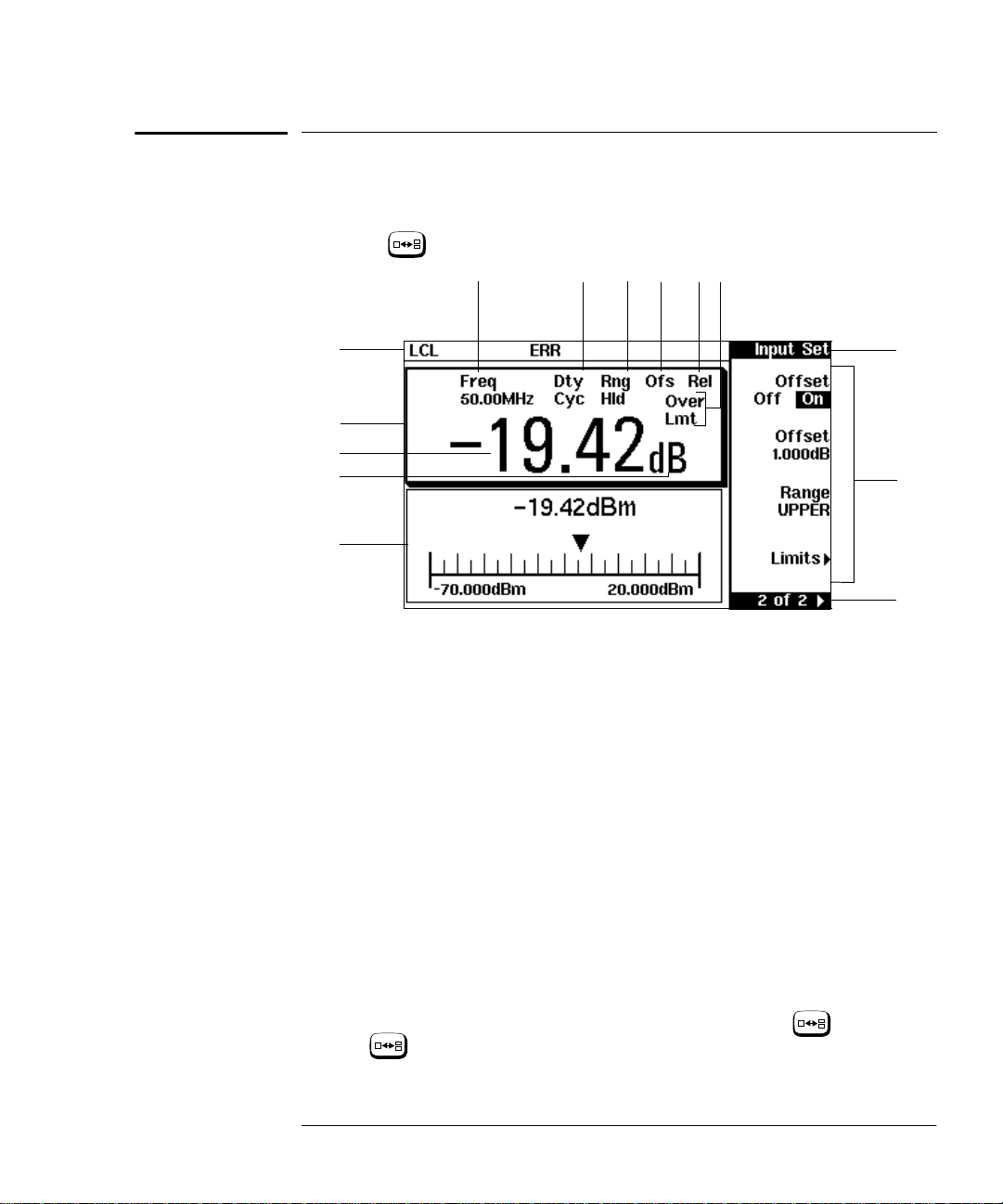
The Display Layout
The following figure details the display layout when two measurement
windows are displayed, one analog and one digital. However it is possible
using the
key to display just o ne measurement window.
14
13
9101112
1
2
3
4
5
1. The status reporting line displays five fields, three associated with
either GP-IB, RS232 or RS422 status and two associated with
error and warning conditions. The first field displays either “RMT”
(remote, GP-IB, RS232 or RS422 operation) or “LCL” (local, front
panel operation).
For GP-IB operation, the second field displays “TLK” if the power
meter is addressed to talk or “LSN” if it is addressed to listen. The
third field indicates an “SRQ” (service request).
For RS232 and RS422 operation, the second field displays “RX”
when data is being recei ved. The third field displays “TX” when the
power meter is transmitting data.
8
7
6
The fourth field indicates “ERR” for any error conditions. The last
field is used to report error and warning messages.
2. The measurement data is di splayed in either one or two
rectangular windows depending on the setting of . Pressing
allows you to toggle bet ween a one or two window display.
When two windows are displayed and this hardkey is pressed the
Agilent E4418B User’s Guide 1-7

Getting Started
The Display Layout
single window then displayed is the one which was previously
highlighted with the shadowed box. On the two window display
the measurement setup menus work on the window which is
shadowed.
3. This is the measurement result field.
4. This field displays the units of measurement, either dBm, dB,
Watts or %.
5. This window is configured to show an analog meter which displays
the measurement result and the meter scaling.
6. This field displays the number of pages in the current softkey
menu. For example, “1 of 2” indicates tha t there are two pages of
softkeys and you are on the first page. Pressing moves you
More
to page “2 of 2”.
7. Any softkeys available are displayed in these four fields.
8. This field displays the title of the menu. For example, when the
power meter is initially switched on the “Contrast” menu is
displayed, and, if you press “Zero/Cal” is displayed.
Zero
Cal
9. This field indicates if the measurement result is outwith the upper
or lower limits set. If the measurement is within the limits this
field is empty. If the measurement result is less than the mi nimum
limit set, “Undr Lmt” is displayed. If the measurement result is
more than the maximum limit set, “Over Lmt” is displayed. Refer
to “Setting Measurement Limits”, on page 2-43 for further
information.
10. This field displays “Rel” if relative mode is on. Refer to “Making
Relative Measurements”, on page 2-34 for further information.
1 1. This field displays “Ofs” if an offset is set. Refer to “Setting
Offsets”, on page 2-36 for further information.
12. This field displays “Rng Hld” i f a range is selected. Refer to
“Setting the Range”, on page 2-52 for further information.
13. This field displays “Dty Cyc” if a duty cycle is set. This allows you
to measure the power of a pulsed signal. Refer to “Measuring
Pulsed Signals”, on page 2-41 for further information.
14. Theinformation in this field is displayed on two lines and depends
on thecombination of sensor type, sensor calibration table and
frequency dependent offset table currently selected. Table 1-1
shows all the possible combinations for the two lines of the display .
Find the table entry which matches your display and use the
reference number in the left-hand column to look up Table 1-2 for
the combination of sensor type and correction being applied to the
1-8 Agilent E4418B User’s Guide

Getting Started
The Display Layout
current measurement.
For example, the display shows:
50MHz
(10,C)
This is equivalent to reference number 4 in Table 1-1 and when
looked up in Table 1-2 shows that:
• the sensor type is 8480 series
• a sensor calibration table is selected (10)
• a frequency dependent offset table is selected(C).
Tabl e 1-1
Reference
Number
1
2
3
4
5
6
Where “y” is the frequency multiplier (M or G), “nn” is the
sensor calibration table number and “a” i s th e f requency
dependent offset table letter.
Upper
Display Line
Lower
Display Line
CF:xxx.x%
CF:xxx.x% xxx.xyHz(a)
xxx.xyHz (nn)
xxx.xyHz (nn,a)
xxx.xyHz
xxx.xyHz (a)
Agilent E4418B User’s Guide 1-9

Getting Started
The Display Layout
Tabl e 1-2
Reference
Number
1
2
3
4
5
6
Sensor
Series
8480
Series
Sensors
E-Series
Sensors
Sensor
Correction
Directly entered
Calibration Factor
Frequency dependent
- from selected sensor
calibration table
Frequency dependent
- downloaded directly
from sensor
Frequency Dependent
Offset Correction
None
From offset table
None
From offset table
None
From offset table
1-10 Agilent E4418B User’s Guid e
 Loading...