


User’s Guide
Agilent Technologies E4406A VSA Series
Transmitter Tester
Manufacturing Part Number: E4406-90130
Printed in USA
February 2000
© Copyright 1999 - 2000 Agilent Technologies, Inc.

The information contained in this document is subject to change
without notice.
Agilent Technologiesmakesnowarrantyofanykindwithregard to this
material, including but not limited to, the implied warranties of
merchantability and fitness for a particular purpose. Agilent
Technologies shall not be liable for errors contained herein or for
incidental or consequential damages in connection with the furnishing,
performance, or use of this material.
Safety Information
The following safety notes are used throughout this manual.
Familiarize yourself with these notes before operating this instrument.
WARNING Warning denotes a hazard. It calls attention to a procedure
which, if not correctly performed or adhered to, could result in
injury or loss of life. Do not proceed beyond a warning note
until the indicated conditions are fully understood and met.
CAUTION Caution denotes a hazard. It calls attention to a procedure that, if not
correctly performed or adhered to, could result in damage to or
destruction of the instrument. Do not proceed beyond a caution sign
until the indicated conditions are fully understood and met.
WARNING This is a Safety Class 1 Product (provided with a protective
earth ground incorporated in the power cord). The mains plug
shall be inserted only in a socket outlet provided with a
protected earth contact. Any interruption of the protective
conductor inside or outside of the product is likely to make the
product dangerous. Intentional interruption is prohibited.
WARNING No operator serviceable parts inside. Refer servicing to
qualified personnel. To prevent electrical shock do not remove
covers.
CAUTION Always use the three-prong AC power cord supplied with this product.
Failure to ensure adequate grounding may cause product damage.
2

Warranty
This Agilent Technologies instrument product is warranted against
defects in material and workmanship for a period of three years from
date of shipment. During the warranty period, Agilent Technologies
will, at its option, either repair or replace products that prove to be
defective.
For warranty service or repair, this product must be returned to a
service facility designated by Agilent Technologies. Buyer shall prepay
shipping charges to Agilent Technologies and Agilent Technologies
shall pay shipping charges to return the product to Buyer. However,
Buyer shall pay all shipping charges, duties, and taxes for products
returned to Agilent Technologies from another country.
Agilent Technologies warrants that its software and firmware
designated by Agilent Technologies for use with an instrument will
execute its programming instructions when properly installed on that
instrument. Agilent Technologies does not warrant that the operation
of the instrument, or software, or firmware will be uninterrupted or
error-free.
LIMITATION OF WARRANTY
The foregoing warranty shall not apply to defects resulting from
improper or inadequate maintenance by Buyer, Buyer-supplied
software or interfacing, unauthorized modification or misuse, operation
outside of the environmental specifications for the product, or improper
site preparation or maintenance.
NO OTHER WARRANTY IS EXPRESSED OR IMPLIED. AGILENT
TECHNOLOGIES SPECIFICALLY DISCLAIMS THE IMPLIED
WARRANTIES OF MERCHANTABILITY AND FITNESS FOR A
PARTICULAR PURPOSE.
EXCLUSIVE REMEDIES
THE REMEDIES PROVIDED HEREIN ARE BUYER’S SOLE AND
EXCLUSIVE REMEDIES. AGILENT TECHNOLOGIES SHALL NOT
BE LIABLE FOR ANY DIRECT, INDIRECT, SPECIAL, INCIDENTAL,
OR CONSEQUENTIAL DAMAGES, WHETHER BASED ON
CONTRACT, TORT, OR ANY OTHER LEGAL THEORY.
3

4

Contents
1. Getting Started
What Comes with the E4406A VSA Series Transmitter Tester . . . . . . . . . . . . . . . . . . . . . . . 17
URL for the Latest VSA Transmitter Tester Update . . . . . . . . . . . . . . . . . . . . . . . . . . . . . . 19
Understanding Digital Communications Measurements. . . . . . . . . . . . . . . . . . . . . . . . . . . 19
Updating the Firmware . . . . . . . . . . . . . . . . . . . . . . . . . . . . . . . . . . . . . . . . . . . . . . . . . . . . . 19
How to Make a Measurement . . . . . . . . . . . . . . . . . . . . . . . . . . . . . . . . . . . . . . . . . . . . . . . . . . 20
Front Panel Key Maps of Context Dependency . . . . . . . . . . . . . . . . . . . . . . . . . . . . . . . . . . . . 21
Front Panel Description. . . . . . . . . . . . . . . . . . . . . . . . . . . . . . . . . . . . . . . . . . . . . . . . . . . . . . . 25
Rear Panel Description . . . . . . . . . . . . . . . . . . . . . . . . . . . . . . . . . . . . . . . . . . . . . . . . . . . . . . . 32
Display Annotation. . . . . . . . . . . . . . . . . . . . . . . . . . . . . . . . . . . . . . . . . . . . . . . . . . . . . . . . . . . 35
Installing Optional
Measurement Personalities. . . . . . . . . . . . . . . . . . . . . . . . . . . . . . . . . . . . . . . . . . . . . . . . . . . .38
Available Personality Options . . . . . . . . . . . . . . . . . . . . . . . . . . . . . . . . . . . . . . . . . . . . . . . . 39
License Key Numbers. . . . . . . . . . . . . . . . . . . . . . . . . . . . . . . . . . . . . . . . . . . . . . . . . . . . . . .39
Installing a License Key Number. . . . . . . . . . . . . . . . . . . . . . . . . . . . . . . . . . . . . . . . . . . . . . 40
Using the Uninstall Key. . . . . . . . . . . . . . . . . . . . . . . . . . . . . . . . . . . . . . . . . . . . . . . . . . . . .41
Cables for Connecting to the Serial Port
(RS-232) . . . . . . . . . . . . . . . . . . . . . . . . . . . . . . . . . . . . . . . . . . . . . . . . . . . . . . . . . . . . . . . . . . . 42
Safety Considerations . . . . . . . . . . . . . . . . . . . . . . . . . . . . . . . . . . . . . . . . . . . . . . . . . . . . . . . . 48
Instrument Installation . . . . . . . . . . . . . . . . . . . . . . . . . . . . . . . . . . . . . . . . . . . . . . . . . . . . .48
Instrument Operation and Maintenance. . . . . . . . . . . . . . . . . . . . . . . . . . . . . . . . . . . . . . . . 49
2. Using System Features
Using System Keys . . . . . . . . . . . . . . . . . . . . . . . . . . . . . . . . . . . . . . . . . . . . . . . . . . . . . . . . . . 52
Install and Uninstall. . . . . . . . . . . . . . . . . . . . . . . . . . . . . . . . . . . . . . . . . . . . . . . . . . . . . . . . 52
Key Locations . . . . . . . . . . . . . . . . . . . . . . . . . . . . . . . . . . . . . . . . . . . . . . . . . . . . . . . . . . . . . . . 53
Using I/O, Front and Rear Panel Keys . . . . . . . . . . . . . . . . . . . . . . . . . . . . . . . . . . . . . . . . . . . 62
Configuring I/O . . . . . . . . . . . . . . . . . . . . . . . . . . . . . . . . . . . . . . . . . . . . . . . . . . . . . . . . . . . . 62
Reference . . . . . . . . . . . . . . . . . . . . . . . . . . . . . . . . . . . . . . . . . . . . . . . . . . . . . . . . . . . . . . . . . 64
Using Alignment & Configuration Keys . . . . . . . . . . . . . . . . . . . . . . . . . . . . . . . . . . . . . . . . . 65
Alignment . . . . . . . . . . . . . . . . . . . . . . . . . . . . . . . . . . . . . . . . . . . . . . . . . . . . . . . . . . . . . . . . 65
Restore Sys Defaults. . . . . . . . . . . . . . . . . . . . . . . . . . . . . . . . . . . . . . . . . . . . . . . . . . . . . . . . 69
Show Errors . . . . . . . . . . . . . . . . . . . . . . . . . . . . . . . . . . . . . . . . . . . . . . . . . . . . . . . . . . . . . . 69
Show System . . . . . . . . . . . . . . . . . . . . . . . . . . . . . . . . . . . . . . . . . . . . . . . . . . . . . . . . . . . . . . 70
System (Local). . . . . . . . . . . . . . . . . . . . . . . . . . . . . . . . . . . . . . . . . . . . . . . . . . . . . . . . . . . . . 70
Using File and Save Keys . . . . . . . . . . . . . . . . . . . . . . . . . . . . . . . . . . . . . . . . . . . . . . . . . . . . . 71
Loading a State . . . . . . . . . . . . . . . . . . . . . . . . . . . . . . . . . . . . . . . . . . . . . . . . . . . . . . . . . . . . 71
Saving a State . . . . . . . . . . . . . . . . . . . . . . . . . . . . . . . . . . . . . . . . . . . . . . . . . . . . . . . . . . . . . 71
Using the Alpha Editor Menu . . . . . . . . . . . . . . . . . . . . . . . . . . . . . . . . . . . . . . . . . . . . . . . . 72
Using Printers . . . . . . . . . . . . . . . . . . . . . . . . . . . . . . . . . . . . . . . . . . . . . . . . . . . . . . . . . . . . . . 73
Selecting a Type of Printer. . . . . . . . . . . . . . . . . . . . . . . . . . . . . . . . . . . . . . . . . . . . . . . . . . .73
How to Print . . . . . . . . . . . . . . . . . . . . . . . . . . . . . . . . . . . . . . . . . . . . . . . . . . . . . . . . . . . . . . 73
How to Save a Screen Image to a Floppy Disc. . . . . . . . . . . . . . . . . . . . . . . . . . . . . . . . . . . . 73
3. Setting the Mode
Selecting a Mode . . . . . . . . . . . . . . . . . . . . . . . . . . . . . . . . . . . . . . . . . . . . . . . . . . . . . . . . . . . . 76
Mode Setup. . . . . . . . . . . . . . . . . . . . . . . . . . . . . . . . . . . . . . . . . . . . . . . . . . . . . . . . . . . . . . . . . 77
Input Keys. . . . . . . . . . . . . . . . . . . . . . . . . . . . . . . . . . . . . . . . . . . . . . . . . . . . . . . . . . . . . . . . 77
5

Contents
Trigger Keys . . . . . . . . . . . . . . . . . . . . . . . . . . . . . . . . . . . . . . . . . . . . . . . . . . . . . . . . . . . . . . .79
Selecting the Frequency/Channel . . . . . . . . . . . . . . . . . . . . . . . . . . . . . . . . . . . . . . . . . . . . . .80
4. Making Measurements
Basic Measurements . . . . . . . . . . . . . . . . . . . . . . . . . . . . . . . . . . . . . . . . . . . . . . . . . . . . . . . . . .82
Preparing for Measurements . . . . . . . . . . . . . . . . . . . . . . . . . . . . . . . . . . . . . . . . . . . . . . . . . . .83
Initial Setup . . . . . . . . . . . . . . . . . . . . . . . . . . . . . . . . . . . . . . . . . . . . . . . . . . . . . . . . . . . . . . .83
Using Measure Keys . . . . . . . . . . . . . . . . . . . . . . . . . . . . . . . . . . . . . . . . . . . . . . . . . . . . . . . .83
Measurement Control . . . . . . . . . . . . . . . . . . . . . . . . . . . . . . . . . . . . . . . . . . . . . . . . . . . . . . .84
Measurement Setup. . . . . . . . . . . . . . . . . . . . . . . . . . . . . . . . . . . . . . . . . . . . . . . . . . . . . . . . .84
Changing the View . . . . . . . . . . . . . . . . . . . . . . . . . . . . . . . . . . . . . . . . . . . . . . . . . . . . . . . . .87
Using Markers . . . . . . . . . . . . . . . . . . . . . . . . . . . . . . . . . . . . . . . . . . . . . . . . . . . . . . . . . . . . .89
Making the Spectrum (Frequency Domain) Measurement. . . . . . . . . . . . . . . . . . . . . . . . . . . .91
Purpose . . . . . . . . . . . . . . . . . . . . . . . . . . . . . . . . . . . . . . . . . . . . . . . . . . . . . . . . . . . . . . . . . .91
Measurement Method . . . . . . . . . . . . . . . . . . . . . . . . . . . . . . . . . . . . . . . . . . . . . . . . . . . . . . .91
Making the Measurement . . . . . . . . . . . . . . . . . . . . . . . . . . . . . . . . . . . . . . . . . . . . . . . . . . . .91
Results . . . . . . . . . . . . . . . . . . . . . . . . . . . . . . . . . . . . . . . . . . . . . . . . . . . . . . . . . . . . . . . . . . .91
Changing the Measurement Setup . . . . . . . . . . . . . . . . . . . . . . . . . . . . . . . . . . . . . . . . . . . . .93
Changing the View . . . . . . . . . . . . . . . . . . . . . . . . . . . . . . . . . . . . . . . . . . . . . . . . . . . . . . . . .97
Using the Markers . . . . . . . . . . . . . . . . . . . . . . . . . . . . . . . . . . . . . . . . . . . . . . . . . . . . . . . . . .97
Troubleshooting Hints . . . . . . . . . . . . . . . . . . . . . . . . . . . . . . . . . . . . . . . . . . . . . . . . . . . . . . .98
Making the Waveform (Time Domain) Measurement . . . . . . . . . . . . . . . . . . . . . . . . . . . . . . . .99
Purpose . . . . . . . . . . . . . . . . . . . . . . . . . . . . . . . . . . . . . . . . . . . . . . . . . . . . . . . . . . . . . . . . . .99
Measurement Method . . . . . . . . . . . . . . . . . . . . . . . . . . . . . . . . . . . . . . . . . . . . . . . . . . . . . . .99
Making the Measurement . . . . . . . . . . . . . . . . . . . . . . . . . . . . . . . . . . . . . . . . . . . . . . . . . . . .99
Results . . . . . . . . . . . . . . . . . . . . . . . . . . . . . . . . . . . . . . . . . . . . . . . . . . . . . . . . . . . . . . . . . .100
Changing the Measurement Setup . . . . . . . . . . . . . . . . . . . . . . . . . . . . . . . . . . . . . . . . . . . .101
Changing the View . . . . . . . . . . . . . . . . . . . . . . . . . . . . . . . . . . . . . . . . . . . . . . . . . . . . . . . .104
Using the Markers . . . . . . . . . . . . . . . . . . . . . . . . . . . . . . . . . . . . . . . . . . . . . . . . . . . . . . . . .104
Troubleshooting Hints . . . . . . . . . . . . . . . . . . . . . . . . . . . . . . . . . . . . . . . . . . . . . . . . . . . . . .105
Making the Channel Power Measurement. . . . . . . . . . . . . . . . . . . . . . . . . . . . . . . . . . . . . . . .106
Purpose . . . . . . . . . . . . . . . . . . . . . . . . . . . . . . . . . . . . . . . . . . . . . . . . . . . . . . . . . . . . . . . . .106
Measurement Method . . . . . . . . . . . . . . . . . . . . . . . . . . . . . . . . . . . . . . . . . . . . . . . . . . . . . .106
Making the Measurement . . . . . . . . . . . . . . . . . . . . . . . . . . . . . . . . . . . . . . . . . . . . . . . . . . .106
Results . . . . . . . . . . . . . . . . . . . . . . . . . . . . . . . . . . . . . . . . . . . . . . . . . . . . . . . . . . . . . . . . . .107
Changing the Measurement Setup . . . . . . . . . . . . . . . . . . . . . . . . . . . . . . . . . . . . . . . . . . . .108
Changing the Display. . . . . . . . . . . . . . . . . . . . . . . . . . . . . . . . . . . . . . . . . . . . . . . . . . . . . . .109
Troubleshooting Hints . . . . . . . . . . . . . . . . . . . . . . . . . . . . . . . . . . . . . . . . . . . . . . . . . . . . . .110
Making the Adjacent Channel Power (ACP) Measurement. . . . . . . . . . . . . . . . . . . . . . . . . .111
Purpose . . . . . . . . . . . . . . . . . . . . . . . . . . . . . . . . . . . . . . . . . . . . . . . . . . . . . . . . . . . . . . . . .111
Measurement Method . . . . . . . . . . . . . . . . . . . . . . . . . . . . . . . . . . . . . . . . . . . . . . . . . . . . . .111
Making the Measurement . . . . . . . . . . . . . . . . . . . . . . . . . . . . . . . . . . . . . . . . . . . . . . . . . . .112
Results . . . . . . . . . . . . . . . . . . . . . . . . . . . . . . . . . . . . . . . . . . . . . . . . . . . . . . . . . . . . . . . . . .112
Changing the Measurement Setup . . . . . . . . . . . . . . . . . . . . . . . . . . . . . . . . . . . . . . . . . . . .114
Changing the View. . . . . . . . . . . . . . . . . . . . . . . . . . . . . . . . . . . . . . . . . . . . . . . . . . . . . . . . .118
Troubleshooting Hints . . . . . . . . . . . . . . . . . . . . . . . . . . . . . . . . . . . . . . . . . . . . . . . . . . . . . .119
Service Measurements . . . . . . . . . . . . . . . . . . . . . . . . . . . . . . . . . . . . . . . . . . . . . . . . . . . . . . .120
Making the Power vs. Time Measurement. . . . . . . . . . . . . . . . . . . . . . . . . . . . . . . . . . . . . . . .121
Purpose . . . . . . . . . . . . . . . . . . . . . . . . . . . . . . . . . . . . . . . . . . . . . . . . . . . . . . . . . . . . . . . . . .121
6

Contents
Measurement Method. . . . . . . . . . . . . . . . . . . . . . . . . . . . . . . . . . . . . . . . . . . . . . . . . . . . . . 121
Making the Measurement . . . . . . . . . . . . . . . . . . . . . . . . . . . . . . . . . . . . . . . . . . . . . . . . . . 121
Results. . . . . . . . . . . . . . . . . . . . . . . . . . . . . . . . . . . . . . . . . . . . . . . . . . . . . . . . . . . . . . . . . . 122
Changing the Measurement Setup . . . . . . . . . . . . . . . . . . . . . . . . . . . . . . . . . . . . . . . . . . . 123
Changing the View . . . . . . . . . . . . . . . . . . . . . . . . . . . . . . . . . . . . . . . . . . . . . . . . . . . . . . . . 124
Timebase Frequency . . . . . . . . . . . . . . . . . . . . . . . . . . . . . . . . . . . . . . . . . . . . . . . . . . . . . . . . 125
Purpose . . . . . . . . . . . . . . . . . . . . . . . . . . . . . . . . . . . . . . . . . . . . . . . . . . . . . . . . . . . . . . . . . 125
Measurement Method. . . . . . . . . . . . . . . . . . . . . . . . . . . . . . . . . . . . . . . . . . . . . . . . . . . . . . 125
Test Setup . . . . . . . . . . . . . . . . . . . . . . . . . . . . . . . . . . . . . . . . . . . . . . . . . . . . . . . . . . . . . . . 125
Results. . . . . . . . . . . . . . . . . . . . . . . . . . . . . . . . . . . . . . . . . . . . . . . . . . . . . . . . . . . . . . . . . . 126
50 MHz Amplitude . . . . . . . . . . . . . . . . . . . . . . . . . . . . . . . . . . . . . . . . . . . . . . . . . . . . . . . . . 127
Purpose . . . . . . . . . . . . . . . . . . . . . . . . . . . . . . . . . . . . . . . . . . . . . . . . . . . . . . . . . . . . . . . . . 127
Measurement Method. . . . . . . . . . . . . . . . . . . . . . . . . . . . . . . . . . . . . . . . . . . . . . . . . . . . . . 127
Test Setup . . . . . . . . . . . . . . . . . . . . . . . . . . . . . . . . . . . . . . . . . . . . . . . . . . . . . . . . . . . . . . . 127
Results. . . . . . . . . . . . . . . . . . . . . . . . . . . . . . . . . . . . . . . . . . . . . . . . . . . . . . . . . . . . . . . . . . 128
Sensors . . . . . . . . . . . . . . . . . . . . . . . . . . . . . . . . . . . . . . . . . . . . . . . . . . . . . . . . . . . . . . . . . . . 129
Purpose . . . . . . . . . . . . . . . . . . . . . . . . . . . . . . . . . . . . . . . . . . . . . . . . . . . . . . . . . . . . . . . . . 129
Measurement Method. . . . . . . . . . . . . . . . . . . . . . . . . . . . . . . . . . . . . . . . . . . . . . . . . . . . . . 129
Test Setup . . . . . . . . . . . . . . . . . . . . . . . . . . . . . . . . . . . . . . . . . . . . . . . . . . . . . . . . . . . . . . . 129
Results. . . . . . . . . . . . . . . . . . . . . . . . . . . . . . . . . . . . . . . . . . . . . . . . . . . . . . . . . . . . . . . . . . 130
Front Panel Test . . . . . . . . . . . . . . . . . . . . . . . . . . . . . . . . . . . . . . . . . . . . . . . . . . . . . . . . . . . 131
Purpose . . . . . . . . . . . . . . . . . . . . . . . . . . . . . . . . . . . . . . . . . . . . . . . . . . . . . . . . . . . . . . . . . 131
Test Setup . . . . . . . . . . . . . . . . . . . . . . . . . . . . . . . . . . . . . . . . . . . . . . . . . . . . . . . . . . . . . . . 131
Results. . . . . . . . . . . . . . . . . . . . . . . . . . . . . . . . . . . . . . . . . . . . . . . . . . . . . . . . . . . . . . . . . . 132
Troubleshooting Hints . . . . . . . . . . . . . . . . . . . . . . . . . . . . . . . . . . . . . . . . . . . . . . . . . . . . . 132
5. Functional Testing
What You'll Find in This Chapter . . . . . . . . . . . . . . . . . . . . . . . . . . . . . . . . . . . . . . . . . . . . . 134
What Are the Functional Tests?. . . . . . . . . . . . . . . . . . . . . . . . . . . . . . . . . . . . . . . . . . . . . . 134
Functional Test Versus Performance Verification. . . . . . . . . . . . . . . . . . . . . . . . . . . . . . . . 134
Getting Started . . . . . . . . . . . . . . . . . . . . . . . . . . . . . . . . . . . . . . . . . . . . . . . . . . . . . . . . . . . . 135
Before You Start . . . . . . . . . . . . . . . . . . . . . . . . . . . . . . . . . . . . . . . . . . . . . . . . . . . . . . . . . . 135
Test Equipment . . . . . . . . . . . . . . . . . . . . . . . . . . . . . . . . . . . . . . . . . . . . . . . . . . . . . . . . . . 135
Equipment Connections . . . . . . . . . . . . . . . . . . . . . . . . . . . . . . . . . . . . . . . . . . . . . . . . . . . . 135
Test Descriptions . . . . . . . . . . . . . . . . . . . . . . . . . . . . . . . . . . . . . . . . . . . . . . . . . . . . . . . . . . . 137
Frequency Response (Flatness). . . . . . . . . . . . . . . . . . . . . . . . . . . . . . . . . . . . . . . . . . . . . . . . 138
Test Limits. . . . . . . . . . . . . . . . . . . . . . . . . . . . . . . . . . . . . . . . . . . . . . . . . . . . . . . . . . . . . . . 138
Test Description . . . . . . . . . . . . . . . . . . . . . . . . . . . . . . . . . . . . . . . . . . . . . . . . . . . . . . . . . . 138
Required Equipment. . . . . . . . . . . . . . . . . . . . . . . . . . . . . . . . . . . . . . . . . . . . . . . . . . . . . . . 138
Procedure. . . . . . . . . . . . . . . . . . . . . . . . . . . . . . . . . . . . . . . . . . . . . . . . . . . . . . . . . . . . . . . . 139
Amplitude Accuracy at 50 MHz. . . . . . . . . . . . . . . . . . . . . . . . . . . . . . . . . . . . . . . . . . . . . . . . 143
Test Limits. . . . . . . . . . . . . . . . . . . . . . . . . . . . . . . . . . . . . . . . . . . . . . . . . . . . . . . . . . . . . . . 143
Test Description . . . . . . . . . . . . . . . . . . . . . . . . . . . . . . . . . . . . . . . . . . . . . . . . . . . . . . . . . . 143
Required Equipment. . . . . . . . . . . . . . . . . . . . . . . . . . . . . . . . . . . . . . . . . . . . . . . . . . . . . . . 143
Procedure. . . . . . . . . . . . . . . . . . . . . . . . . . . . . . . . . . . . . . . . . . . . . . . . . . . . . . . . . . . . . . . . 144
Input Attenuator Accuracy at 50 MHz . . . . . . . . . . . . . . . . . . . . . . . . . . . . . . . . . . . . . . . . . . 148
Test Limits . . . . . . . . . . . . . . . . . . . . . . . . . . . . . . . . . . . . . . . . . . . . . . . . . . . . . . . . . . . . . . 148
Test Description . . . . . . . . . . . . . . . . . . . . . . . . . . . . . . . . . . . . . . . . . . . . . . . . . . . . . . . . . . 148
Required Equipment. . . . . . . . . . . . . . . . . . . . . . . . . . . . . . . . . . . . . . . . . . . . . . . . . . . . . . . 148
7

Contents
Procedure . . . . . . . . . . . . . . . . . . . . . . . . . . . . . . . . . . . . . . . . . . . . . . . . . . . . . . . . . . . . . . . .148
Displayed Average Noise Level (DANL). . . . . . . . . . . . . . . . . . . . . . . . . . . . . . . . . . . . . . . . . .151
Test Limits . . . . . . . . . . . . . . . . . . . . . . . . . . . . . . . . . . . . . . . . . . . . . . . . . . . . . . . . . . . . . . .151
Test Description . . . . . . . . . . . . . . . . . . . . . . . . . . . . . . . . . . . . . . . . . . . . . . . . . . . . . . . . . . .151
Required Equipment . . . . . . . . . . . . . . . . . . . . . . . . . . . . . . . . . . . . . . . . . . . . . . . . . . . . . . .151
Procedure . . . . . . . . . . . . . . . . . . . . . . . . . . . . . . . . . . . . . . . . . . . . . . . . . . . . . . . . . . . . . . . .152
Phase Noise . . . . . . . . . . . . . . . . . . . . . . . . . . . . . . . . . . . . . . . . . . . . . . . . . . . . . . . . . . . . . . . .154
Test Limits. . . . . . . . . . . . . . . . . . . . . . . . . . . . . . . . . . . . . . . . . . . . . . . . . . . . . . . . . . . . . . .154
Test Description . . . . . . . . . . . . . . . . . . . . . . . . . . . . . . . . . . . . . . . . . . . . . . . . . . . . . . . . . . .154
Required Equipment . . . . . . . . . . . . . . . . . . . . . . . . . . . . . . . . . . . . . . . . . . . . . . . . . . . . . . .155
Procedure . . . . . . . . . . . . . . . . . . . . . . . . . . . . . . . . . . . . . . . . . . . . . . . . . . . . . . . . . . . . . . . .155
Residual Responses . . . . . . . . . . . . . . . . . . . . . . . . . . . . . . . . . . . . . . . . . . . . . . . . . . . . . . . . . .160
Test Limits. . . . . . . . . . . . . . . . . . . . . . . . . . . . . . . . . . . . . . . . . . . . . . . . . . . . . . . . . . . . . . .160
Test Description . . . . . . . . . . . . . . . . . . . . . . . . . . . . . . . . . . . . . . . . . . . . . . . . . . . . . . . . . . .160
Required Equipment . . . . . . . . . . . . . . . . . . . . . . . . . . . . . . . . . . . . . . . . . . . . . . . . . . . . . . .160
Procedure . . . . . . . . . . . . . . . . . . . . . . . . . . . . . . . . . . . . . . . . . . . . . . . . . . . . . . . . . . . . . . . .160
6. If You Have a Problem
Problem Symptoms and Solutions . . . . . . . . . . . . . . . . . . . . . . . . . . . . . . . . . . . . . . . . . . . . . .166
Key or Feature Does Not Appear in Menu . . . . . . . . . . . . . . . . . . . . . . . . . . . . . . . . . . . . . .166
Frequency Unlock or External Reference Missing - Error Messages . . . . . . . . . . . . . . . . .167
LAN External Loopback Test Failed - Error Message . . . . . . . . . . . . . . . . . . . . . . . . . . . . .167
Instrument Fails Alignment - Error Message . . . . . . . . . . . . . . . . . . . . . . . . . . . . . . . . . . .167
Measurement Keys Do Not Appear after Pressing the Mode Key . . . . . . . . . . . . . . . . . . .168
Instrument Power-On Problem . . . . . . . . . . . . . . . . . . . . . . . . . . . . . . . . . . . . . . . . . . . . . . .168
LAN Communication Problem. . . . . . . . . . . . . . . . . . . . . . . . . . . . . . . . . . . . . . . . . . . . . . . .168
Error Queues . . . . . . . . . . . . . . . . . . . . . . . . . . . . . . . . . . . . . . . . . . . . . . . . . . . . . . . . . . . . . . .169
Front Panel Error Messages . . . . . . . . . . . . . . . . . . . . . . . . . . . . . . . . . . . . . . . . . . . . . . . . .169
SCPI Remote Interface Error Messages . . . . . . . . . . . . . . . . . . . . . . . . . . . . . . . . . . . . . . . .172
Clearing the Error Queue . . . . . . . . . . . . . . . . . . . . . . . . . . . . . . . . . . . . . . . . . . . . . . . . . . .173
No Error . . . . . . . . . . . . . . . . . . . . . . . . . . . . . . . . . . . . . . . . . . . . . . . . . . . . . . . . . . . . . . . . .173
Error Message Descriptions . . . . . . . . . . . . . . . . . . . . . . . . . . . . . . . . . . . . . . . . . . . . . . . . . . .174
Messages with No Numbers . . . . . . . . . . . . . . . . . . . . . . . . . . . . . . . . . . . . . . . . . . . . . . . . .174
Query Error Messages
[−499 to −400] . . . . . . . . . . . . . . . . . . . . . . . . . . . . . . . . . . . . . . . . . . . . . . . . . . . . . . . . . . . . .175
Device-Specific Error Messages
[−399 to −300] . . . . . . . . . . . . . . . . . . . . . . . . . . . . . . . . . . . . . . . . . . . . . . . . . . . . . . . . . . . . .177
Execution Error Messages
[−299 to −200] . . . . . . . . . . . . . . . . . . . . . . . . . . . . . . . . . . . . . . . . . . . . . . . . . . . . . . . . . . . . .179
Command Error Messages
[−199 to −100] . . . . . . . . . . . . . . . . . . . . . . . . . . . . . . . . . . . . . . . . . . . . . . . . . . . . . . . . . . . . .186
Instrument-Specific Error Messages
[positive numbers] . . . . . . . . . . . . . . . . . . . . . . . . . . . . . . . . . . . . . . . . . . . . . . . . . . . . . . . . .191
Core-Specific Error Messages
[1 to 99] . . . . . . . . . . . . . . . . . . . . . . . . . . . . . . . . . . . . . . . . . . . . . . . . . . . . . . . . . . . . . . . . . .191
GSM-Specific Error Messages
[100 to 199] . . . . . . . . . . . . . . . . . . . . . . . . . . . . . . . . . . . . . . . . . . . . . . . . . . . . . . . . . . . . . . .195
CDMA-Specific Error Messages
[200 to 299] . . . . . . . . . . . . . . . . . . . . . . . . . . . . . . . . . . . . . . . . . . . . . . . . . . . . . . . . . . . . . . .197
8

Contents
NADC-Specific Error Messages
[300 to 399] . . . . . . . . . . . . . . . . . . . . . . . . . . . . . . . . . . . . . . . . . . . . . . . . . . . . . . . . . . . . . . 198
PDC-Specific Error Messages
[400 to 499] . . . . . . . . . . . . . . . . . . . . . . . . . . . . . . . . . . . . . . . . . . . . . . . . . . . . . . . . . . . . . . 199
Warranty Information . . . . . . . . . . . . . . . . . . . . . . . . . . . . . . . . . . . . . . . . . . . . . . . . . . . . . . . 200
Returning Your Instrument to Agilent Technologies. . . . . . . . . . . . . . . . . . . . . . . . . . . . . . . 201
Blue Repair Tag goes here. . . . . . . . . . . . . . . . . . . . . . . . . . . . . . . . . . . . . . . . . . . . . . . . . . . . 203
7. Options and Accessories
Options and Measurement Personalities . . . . . . . . . . . . . . . . . . . . . . . . . . . . . . . . . . . . . . . . 206
Option BAH. . . . . . . . . . . . . . . . . . . . . . . . . . . . . . . . . . . . . . . . . . . . . . . . . . . . . . . . . . . . . . 206
Option BAC . . . . . . . . . . . . . . . . . . . . . . . . . . . . . . . . . . . . . . . . . . . . . . . . . . . . . . . . . . . . . . 206
Option BAE . . . . . . . . . . . . . . . . . . . . . . . . . . . . . . . . . . . . . . . . . . . . . . . . . . . . . . . . . . . . . . 206
Option HN1 . . . . . . . . . . . . . . . . . . . . . . . . . . . . . . . . . . . . . . . . . . . . . . . . . . . . . . . . . . . . . . 206
Option BAF . . . . . . . . . . . . . . . . . . . . . . . . . . . . . . . . . . . . . . . . . . . . . . . . . . . . . . . . . . . . . . 206
Option B78. . . . . . . . . . . . . . . . . . . . . . . . . . . . . . . . . . . . . . . . . . . . . . . . . . . . . . . . . . . . . . . 206
Option 300 . . . . . . . . . . . . . . . . . . . . . . . . . . . . . . . . . . . . . . . . . . . . . . . . . . . . . . . . . . . . . . . 206
Option 0B1. . . . . . . . . . . . . . . . . . . . . . . . . . . . . . . . . . . . . . . . . . . . . . . . . . . . . . . . . . . . . . . 207
Option 0BV . . . . . . . . . . . . . . . . . . . . . . . . . . . . . . . . . . . . . . . . . . . . . . . . . . . . . . . . . . . . . . 207
Option 0BW. . . . . . . . . . . . . . . . . . . . . . . . . . . . . . . . . . . . . . . . . . . . . . . . . . . . . . . . . . . . . . 207
Option 1CM . . . . . . . . . . . . . . . . . . . . . . . . . . . . . . . . . . . . . . . . . . . . . . . . . . . . . . . . . . . . . . 207
Option 1CN . . . . . . . . . . . . . . . . . . . . . . . . . . . . . . . . . . . . . . . . . . . . . . . . . . . . . . . . . . . . . . 207
Option 1CP . . . . . . . . . . . . . . . . . . . . . . . . . . . . . . . . . . . . . . . . . . . . . . . . . . . . . . . . . . . . . . 207
Option 1CR . . . . . . . . . . . . . . . . . . . . . . . . . . . . . . . . . . . . . . . . . . . . . . . . . . . . . . . . . . . . . . 207
VSA Transmitter Tester Measurement Personalities Retrofit. . . . . . . . . . . . . . . . . . . . . . 208
Accessories . . . . . . . . . . . . . . . . . . . . . . . . . . . . . . . . . . . . . . . . . . . . . . . . . . . . . . . . . . . . . . . . 209
AC Probe . . . . . . . . . . . . . . . . . . . . . . . . . . . . . . . . . . . . . . . . . . . . . . . . . . . . . . . . . . . . . . . . 209
Broadband Preamplifiers and Power Amplifiers . . . . . . . . . . . . . . . . . . . . . . . . . . . . . . . . 209
GPIB Cable . . . . . . . . . . . . . . . . . . . . . . . . . . . . . . . . . . . . . . . . . . . . . . . . . . . . . . . . . . . . . . 209
Parallel Interface Cable . . . . . . . . . . . . . . . . . . . . . . . . . . . . . . . . . . . . . . . . . . . . . . . . . . . . 209
Printer . . . . . . . . . . . . . . . . . . . . . . . . . . . . . . . . . . . . . . . . . . . . . . . . . . . . . . . . . . . . . . . . . . 209
RS-232 Cables . . . . . . . . . . . . . . . . . . . . . . . . . . . . . . . . . . . . . . . . . . . . . . . . . . . . . . . . . . . 210
N2714A Calibration and Adjustment Software. . . . . . . . . . . . . . . . . . . . . . . . . . . . . . . . . . 210
Support Documentation. . . . . . . . . . . . . . . . . . . . . . . . . . . . . . . . . . . . . . . . . . . . . . . . . . . . . . 211
9

Contents
10

List of Key Descriptions
10 MHz Out............................................................................................................................................64
50 MHz Amplitude...............................................................................................................................127
50 MHz Amptd.....................................................................................................................................127
50 MHz Ref.............................................................................................................................................77
Abs Limit..............................................................................................................................................116
Absolute................................................................................................................................................116
ADC Dither ..........................................................................................................................................103
ADC Range.............................................................................................................................................95
Adjacent Channel Power.....................................................................................................................112
Advanced................................................................................................................................................84
Align 50 MHz Reference........................................................................................................................66
Align ADC ..............................................................................................................................................66
Align All Now.........................................................................................................................................66
Align Current IF Flatness.....................................................................................................................67
Align Current SysGain..........................................................................................................................67
Align IF...................................................................................................................................................66
Align RF .................................................................................................................................................66
Align Subsystem....................................................................................................................................66
Alignments.............................................................................................................................................65
Alpha Editor...........................................................................................................................................72
Auto Align ..............................................................................................................................................66
Auto Peak...............................................................................................................................................95
Auto Trig ................................................................................................................................................79
Auto ........................................................................................................................................................95
AutoPeakLock........................................................................................................................................96
Average...................................................................................................................................................85
Avg Bursts..............................................................................................................................................85
Avg Mode................................................................................................................................................85
Avg Number...........................................................................................................................................85
Avg Type.................................................................................................................................................86
Band Power............................................................................................................................................90
Bar Graph.............................................................................................................................................118
Basic .......................................................................................................................................................76
Blackman Harris....................................................................................................................................95
Blackman................................................................................................................................................95
Burst.....................................................................................................................................................124
cdmaOne.................................................................................................................................................76
Chan Pwr Span....................................................................................................................................108
Channel Power.....................................................................................................................................106
Clear Error Queue(s).............................................................................................................................69
Config I/O ...............................................................................................................................................62
Corrections.............................................................................................................................................67
Current...................................................................................................................................................87
Data Packing..........................................................................................................................................96
Data Points...........................................................................................................................................109
Decimation ...........................................................................................................................................103
Delay.......................................................................................................................................................79
Delta.......................................................................................................................................................90
Diagnostics.............................................................................................................................................70
11

List of Key Descriptions
Emulated GPIB Address........................................................................................................................63
Emulated GPIB Logical Unit ................................................................................................................63
Emulated GPIB Name...........................................................................................................................63
ESC.........................................................................................................................................................65
Ethernet Addr ........................................................................................................................................63
Exit Main Firmware ..............................................................................................................................38
Ext Atten ..............................................................................................................................................110
Ext Front ................................................................................................................................................80
Ext Rear..................................................................................................................................................80
Fail........................................................................................................................................................116
FFT Length ............................................................................................................................................95
FFT Size .................................................................................................................................................95
FFT Window...........................................................................................................................................95
File Location...........................................................................................................................................73
File System.............................................................................................................................................63
File Type.................................................................................................................................................73
Flat Top...................................................................................................................................................95
Frame Timer...........................................................................................................................................80
Frame......................................................................................................................................................86
Free Run.................................................................................................................................................86
Freq Ref..................................................................................................................................................64
Front Panel Test...................................................................................................................................131
Function................................................................................................................................................105
Gaussian.................................................................................................................................................95
GPIB Address.........................................................................................................................................62
GSM........................................................................................................................................................76
Hamming................................................................................................................................................95
Hanning..................................................................................................................................................95
Host Name..............................................................................................................................................63
I only.......................................................................................................................................................77
I/Q Input Z..............................................................................................................................................78
I/Q ...........................................................................................................................................................77
IF Align...................................................................................................................................................77
Input Atten.............................................................................................................................................78
Input Port...............................................................................................................................................77
Install......................................................................................................................................................38
Instrument Logical Unit........................................................................................................................63
Instrument Name...................................................................................................................................63
Integ BW...............................................................................................................................................108
IP Address ..............................................................................................................................................62
K-B 70dB / 90dB/ 110dB (Kaiser-Bessel)..............................................................................................95
Length Ctrl.............................................................................................................................................95
Level........................................................................................................................................................79
License Key ............................................................................................................................................39
License Key ............................................................................................................................................40
Limit Setup...........................................................................................................................................116
Line.........................................................................................................................................................86
Load State ..............................................................................................................................................71
Log-Pwr Avg...........................................................................................................................................86
12

List of Key Descriptions
Long (32 bit).........................................................................................................................................103
Manual ...................................................................................................................................................96
Marker All Off........................................................................................................................................90
Max Total Pwr........................................................................................................................................78
Maximum Connections..........................................................................................................................63
Maximum ...............................................................................................................................................86
Meas Time............................................................................................................................................123
Meas Type ............................................................................................................................................117
Medium (24 bit)....................................................................................................................................103
Min Pts in RBW.....................................................................................................................................95
Minimum................................................................................................................................................86
Noise.......................................................................................................................................................90
Normal....................................................................................................................................................89
Num FFT Seg.......................................................................................................................................117
Offset Adv.............................................................................................................................................117
Offset Freq............................................................................................................................................116
Offset Side............................................................................................................................................116
Offset ....................................................................................................................................................116
Offset ......................................................................................................................................................80
Peak Level..............................................................................................................................................79
Period......................................................................................................................................................80
Pos...........................................................................................................................................................79
Pre-ADC BPF.........................................................................................................................................94
Pre-FFT BW...........................................................................................................................................94
Pre-FFT Fltr...........................................................................................................................................94
Print To...................................................................................................................................................73
PSD Ref ................................................................................................................................................117
Pwr Avg..................................................................................................................................................86
Pwr vs Time .........................................................................................................................................121
RBW Filter...........................................................................................................................................123
Ref Position............................................................................................................................................88
Ref Value ................................................................................................................................................88
Reference................................................................................................................................................64
Rel Lim (Car)........................................................................................................................................117
Rel Lim (PSD)......................................................................................................................................117
Relative Att..........................................................................................................................................117
Relative.................................................................................................................................................117
Res BW...................................................................................................................................................84
Reset Offset............................................................................................................................................80
Restore Align Defaults...........................................................................................................................67
Restore Meas Defaults...........................................................................................................................84
Restore Sys Defaults..............................................................................................................................69
Resume...................................................................................................................................................84
RF Burst (Wideband).............................................................................................................................79
RF ...........................................................................................................................................................77
Rise & Fall............................................................................................................................................124
Save State...............................................................................................................................................71
Scale/Coupling........................................................................................................................................88
Scale/Div.................................................................................................................................................88
13

List of Key Descriptions
SCPI Lan ................................................................................................................................................63
Select.......................................................................................................................................................90
Sensors..................................................................................................................................................129
Server......................................................................................................................................................63
Service ....................................................................................................................................................76
Shape ......................................................................................................................................................90
Short (16 bit) ........................................................................................................................................103
Show Errors............................................................................................................................................69
Show System ..........................................................................................................................................70
SICL Server............................................................................................................................................63
Signal Amptd..........................................................................................................................................78
Signal Rate.............................................................................................................................................78
Signal Type.............................................................................................................................................78
Slope........................................................................................................................................................79
Socket Port..............................................................................................................................................63
Span........................................................................................................................................................88
Spectrum (Freq Domain).......................................................................................................................91
Spectrum ..............................................................................................................................................118
Sweep Time ............................................................................................................................................88
Sync Source ............................................................................................................................................80
Telnet Port..............................................................................................................................................63
Time Corr ...............................................................................................................................................67
Timebase Frequency............................................................................................................................125
Total Pwr Ref........................................................................................................................................117
Trace.......................................................................................................................................................89
Trig Holdoff ............................................................................................................................................79
Trigger....................................................................................................................................................79
Uniform...................................................................................................................................................95
Uninstall.................................................................................................................................................41
Video (IF Envlp).....................................................................................................................................79
Visible Align...........................................................................................................................................68
Voltage Avg.............................................................................................................................................86
Waveform (Time Domain)......................................................................................................................99
Window Length......................................................................................................................................95
14

1 Getting Started
This chapter introduces you to basic features of the instrument,
including the front panel keys, rear panel connections, and display
annotation. You will also find processes for making a basic
measurement and for installing applications.
15

Getting Started
Topics include:
“What Comes with the E4406A VSA Series Transmitter Tester” on
page 17
“How to Make a Measurement” on page 20
“Front Panel Key Maps of Context Dependency” on page 21
“Front Panel Description” on page 25
“Rear Panel Description” on page 32
“Display Annotation” on page 35
“Installing Optional Measurement Personalities” on page 38
“Safety Considerations” on page 48
“Cables for Connecting to the Serial Port (RS-232)” on page 42
16 Chapter1

Getting Started
What Comes with the E4406A VSA Series Transmitter Tester
What Comes with the E4406A VSA Series
Transmitter Tester
With your purchase of the instrument you receive the following
materials:
Table 1-1 Standard Documentation
Part Description Notes
User’s Guide Includes E4406-90057 and E4406-90085
Specifications Includes specifications for most optional
measurement personalities. Special
handling options may be documented
elsewhere.
Programmer’s Guide Does not include commands for the
optional measurement personalities
Documentation and
Instrument Driver CD-ROM
Includes programming examples, does
not include service documentation or
software
An E4406A standard instrument contains the Basic and Service modes.
If you have purchased an optional measurement personality, your
instrument comes loaded with the personality you have selected plus
the Basic and Service modes. You also receive the related measurement
and programming guides for the options you have ordered.
Chapter 1 17

Getting Started
What Comes with the E4406A VSA Series Transmitter Tester
Table 1-2 Personality Documentation
Measurement Option Part Description
Option BAC cdmaOne Measurement Guide
cdmaOne Programming Commands
Option BAH GSM Measurement Guide
GSM Programming Commands
Option BAE NADC, PDC Measurement Guide
NADC, PDC Programming Commands
Option HN! iDEN Measurement Guide
(includes programming commands)
Option BAF W-CDMA Measurement Guide
W-CDMA Programming Commands
Option B78 cdma2000 Measurement Guide
cdma2000 Programming Commands
Service documentation is available from Agilent Technologies.
NOTE If the shipping container is damaged, or any part is missing, notify
Agilent Technologies (see page 201 for locations). When transporting
the instrument use the original packaging or comparable packaging.
18 Chapter1

Getting Started
What Comes with the E4406A VSA Series Transmitter Tester
URL for the Latest VSA Transmitter Tester Update
For the latest information about this instrument, including firmware
upgrades, application information, and product information, please
visit the following URL: www.agilent.com/find/vsa/.
Understanding Digital Communications
Measurements
Additional measurement application information is available through
your local Agilent Technologies sales and service office. See the “If You
Have a Problem” chapter for office location information. Some available
application notes are listed below.
Description
Digital Modulation in Communications Systems An Introduction
Application Note 1298
Understanding CDMA Measurements for Base
Stations and Their Components
Application Note 1311
Understanding GSM Transmitter Measurements for
Base Transceiver Stations and Mobile Stations
Application Note 1312
Agilent Part
Number
5965-7160E
5968-0953E
5966-2833E
Updating the Firmware
Updated versions of the E4406A VSA Transmitter Tester firmware will
be available via several sources. Information on the latest firmware
revision can be accessed through the following URL.
URL to Contact to Obtain Firmware Update Information
www.agilent.com/find/vsa/
Chapter 1 19

Getting Started
How to Make a Measurement
How to Make a Measurement
The Making Measurements chapter is organized to help you follow the
three-step process shown in the table below.
Step Primary Key Setup Keys Related Keys
1. Select &
setup a mode
2. Select &
setup a measurement
3. Select &
setup view
The VSA E4406A transmitter tester enables you to make a wide variety
of digital measurements, both through its native spectrum and
waveform measurement capabilities, and through the measurement
personality option(s) you have purchased to activate applications
specific measurements that are based upon industry standards.
Mode Mode Setup, Input,
Frequency Channel
Measure Meas Setup Meas Control,
View/Trace Span X Scale,
Amplitude Y Scale
Next Window, Zoom
, Display,
System
Restart
File
, Save,
Print, Print Setup,
Marker, Search
20 Chapter1
Getting Started
Front Panel Key Maps of Context Dependency
Front Panel Key Maps of Context Dependency
Many of the instrument features are context dependent. The functions
that are available will change based on your selections of mode, mode
setup, measurement, and measurement setup. The following figures
represent the dependency relationships of the front panel keys.
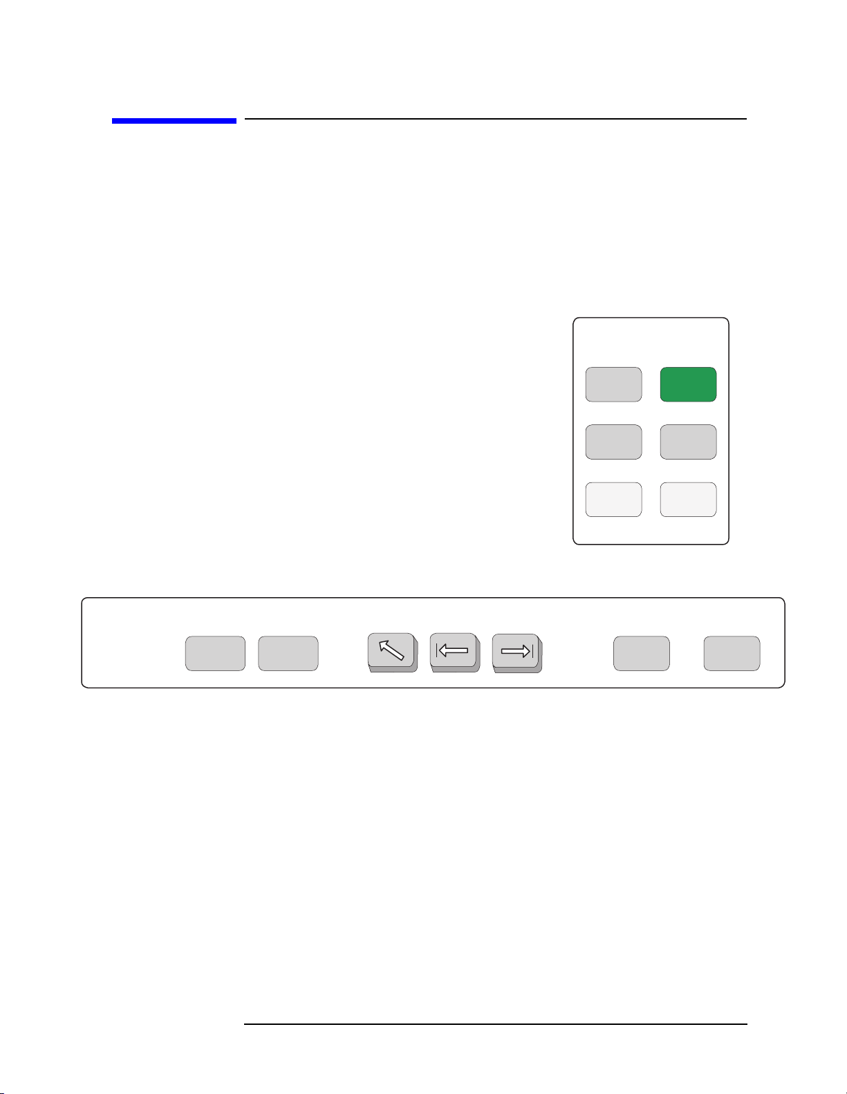
Figure 1-1 System and Navigation Keys are not Context Dependent
System
PresetSystem
Navigation
Next
Window
File
Save
Print
Setup
Print
TabWindow
Zoom Return Esc
Chapter 1 21

Getting Started
Front Panel Key Maps of Context Dependency
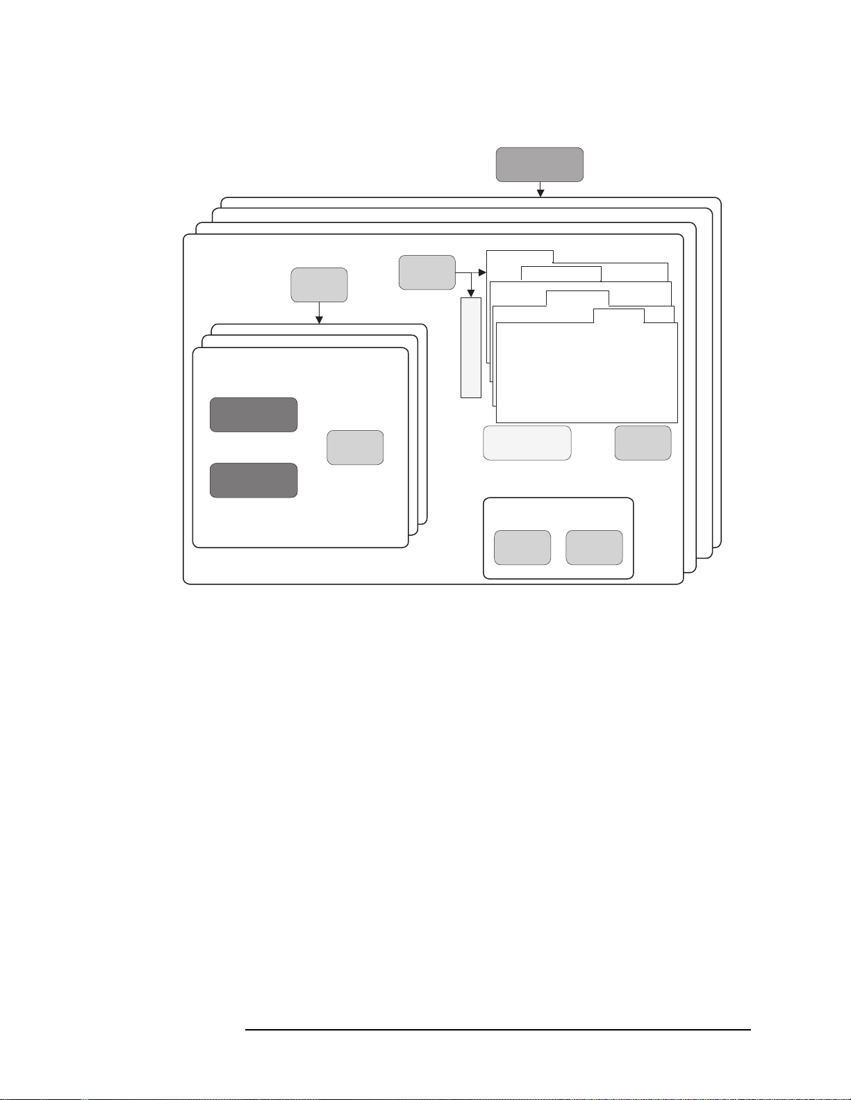
Figure 1-2 Context Dependent on the Selected Mode and Mode Setup
MODE
Service
GSM
cdmaOne
Channel Power
Statistics View
Spectrum View
I/Q View
SPAN
X Scale
AMPLITUDE
Y Scale
Waveform (Time Domain)
Spectrum (Freq Domain)
Spurious Close
View/
Trace
Display
Meas
Setup
M
e
n
u
s
MEASURE
Averaging
Trigger Source
Advanced
Restart
Marker
Limits
Meas
Control
Mode
Setup
Radio
Standard: TIA-95B PCS
Device: MS, BS
Input
Trigger
FREQUENCY
Channel
Demod
RF Chan
Frame
Input
Marker
Search
22 Chapter1
Getting Started
Front Panel Key Maps of Context Dependency
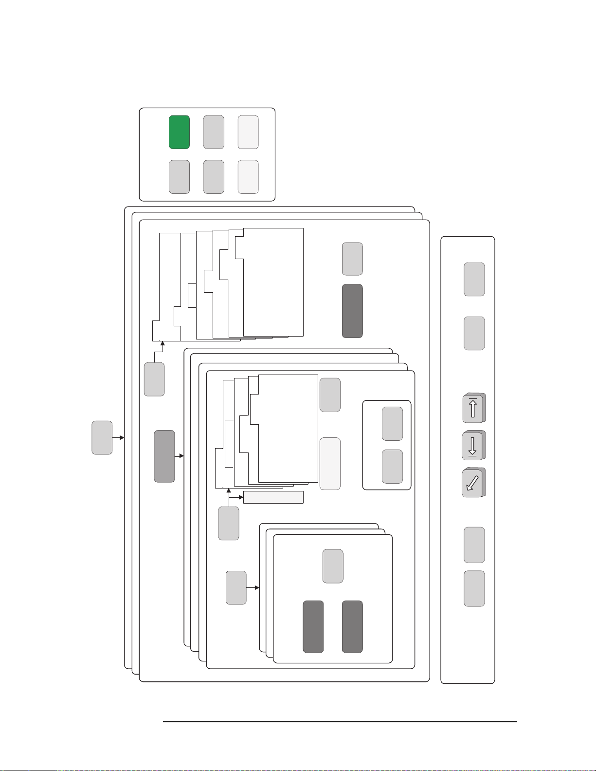
Figure 1-3 Context Dependent on the Selected Measure and Meas Setup
Waveform (Time Domain)
Spectrum (Freq Domain)
Spurious Close
Channel Power
Statistics View
Spectrum View
I/Q View
SPAN
X Scale
AMPLITUDE
Y Scale
View/
Trace
Display
Meas
Setup
*
M
e
n
u
s
MEASURE
Averaging
Trigger Source
Restart
Marker
*
Advanced
Limits
Meas
Control
Marker
Search
* Some Measure and Meas Setup parameters are context dependent upon the
Radio variant and Device selected in the Mode Setup.
Chapter 1 23
Getting Started
Front Panel Key Maps of Context Dependency
Figure 1-4 Front Panel Keys Context Dependent Relationships
System
Device: MS, BS
Standard: TIA-95B PCS
Radio
Mode
Setup
PresetSystem
Trigger
Input
Print
Setup
File
Demod
Frame
RF Chan
Print
Save
Limits
Meas
Control
Input
FREQUENCY
Channel
MODE
Service
GSM
cdmaOne
MEASURE
Waveform (Time Domain)
Spectrum (Freq Domain)
Spurious Close
Channel Power
Advanced
Trigger Source
Averaging
Meas
Setup
View/
Trace
enu
M
Statistics View
Spectrum View
I/Q View
Search
TabWindow
Marker
Restart
s
Display
SPAN
X Scale
AMPLITUDE
Y Scale
Marker
Zoom Return Esc
Next
Window
Navigation
24 Chapter1

Getting Started
Front Panel Description
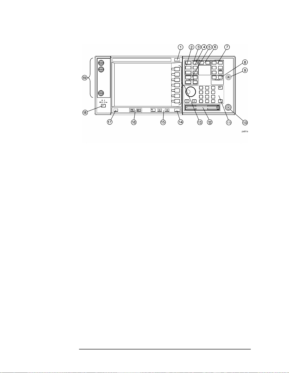
Front Panel Description
The hardkeys, softkeys and menus, RPG knob and step keys, and front
panel inputs are explained below.
Softkeys either activate a feature or access a further softkey menu.
There are seven softkeys. The softkey which is currently active is
highlighted. Softkeys which are not available for use are greyed-out.
The transmitter tester uses five types of softkey:
• Menu softkeys. An arrow on the right side of a key label indicates
that the key accesses a further menu.
• Toggle softkeys. A toggle softkey allows you to select between one of
several settings (usually two settings, but there may be more) that
are shown on a softkey; the available settings are listed underneath
the softkey label, and the currently active setting is underlined.
Pressing the toggle softkey will result in activating a setting that is
adjacent to the initial, underlined setting.
• Numeric softkeys. A numeric softkey allows you to modify a
numerical value. Current values are shown in the active function
area of the display.
• Numeric + Toggle softkeys. A numeric + toggle softkey allows you,
first, to toggle between an automatic or manual mode, and then, if
you have selected manual, allows you to enter a numeric value.
• Immediate action softkeys. An immediate action softkey activates a
feature immediately upon being pressed.
Softkey menus are dependent on the measurement chosen or the front
panel key that has been activated. Many softkey menus contain more
than seven softkeys, and cannot be displayed on a single-page menu.
Multiple page menus are accessed by pressing a
the bottom key of the menu.
Paths to access any feature will be found in the key access table on
page 53. Display annotation is explained on page 35. Operation of the
3.5 inch floppy-drive is covered in the section on printing on page 73.
More key, which will be
Chapter 1 25
Getting Started
Front Panel Description
1. ESC key Use the escape key to exit any function without
modifying current parameters. Pressing the
ESC key
will:
• Clear any numeric entry that you have begun to
enter but decided you want to cancel.
• Remove any entries that are visible in the active
function area of the display (see the section on
annotation on page 35 for a description of the active
function area and other display features).
• Cancels a print, if one is in progress.
• Cancels an alignment, if one is in progress.
2. Control keys set parameters that are used by the measurement in
the current measurement mode.
• FREQUENCY/Channel accesses softkeys that
control the center frequency or channel number.
These parameters apply to all measurements in the
current mode.
• SPAN/X Scale accesses softkeys that control the
horizontal scale in units of frequency, time, symbols
or bits. The parameters in this menu apply only to
the active window in the current measurement. See
page 87 for more detail.
26 Chapter1

Getting Started
Front Panel Description
• AMPLITUDE/Y Scale accesses softkeys that control
vertical scale functions in units of dBm, dB, volts,
degrees, or radians. The parameters in this menu
apply only to the active window in the current
measurement. See page 87 for more detail.
3. Input key The
Input key accesses softkeys that control the input of
the transmitter tester. These affect all measurements
within the current mode. Note that the internal
50 MHz reference signal and the IF align signal are
used as internal inputs that do not require external
connections. See page 65 for more detail.
4. View keys
View keys modify the format of the trace and numeric
data on the display. See page 87 for more detail.
•
View/Trace accesses softkeys that control the way
results are viewed.
• Display accesses softkeys that change the display.
Functions such as limit mask on/off and dots on/off
are available for some measurements.
5. Measure keys are used to select and set up a specific
measurement within the selected application. See page
83 for more detail.
•
MEASURE accesses softkeys that select and initiate
the various measurements that are specific to the
current mode.
•
Meas Setup accesses the setup parameters that are
specific to the current measurement.
• Restart causes the measurement that is currently in
process to stop, then start again at the beginning
according to the current measurement setup
parameters.
•
Meas Control accesses softkeys that affect the
measurement after it has been setup, for example
selecting a single or continuous measurement.
6. Mode keys select the measurement mode and mode parameters
such as input and trigger settings. See page 77 for
more detail.
•
MODE accesses softkeys to select the instrument
mode. Each mode is independent of all other modes.
• Mode Setup accesses softkeys that affect parameters
that are specific to the current mode and affect all
measurements within that mode.
Chapter 1 27

Getting Started
Front Panel Description
7. System keys access system features, that are used with all
instrument modes. See page 52 for further explanation
of system features.
•
System accesses features that control instrument
configuration at the system level, like I/O
configuration and alignment, which affect all
instrument modes. Pressing
System also returns the
instrument to local control, if it has been in remote
mode.
•
Preset resets all parameters of the current mode
back to the factory defaults.
• Print immediately prints what is on the screen to the
printer, or saves a file to a floppy disc, according to
the parameters that are currently set in the
Setup menu. See page 73 for more detail.
Print Setup configures the transmitter tester for
•
printing to a printer, or saving an image file to the
floppy disc drive, and also allows you to select the
printer type.
Print
•
File accesses softkeys that control the file system of
the transmitter tester for saving and loading
instrument states. See page 71 for more detail.
•
Save saves the current instrument state in the File
menu. See page 71 for more detail.
8. Marker keys are used to obtain specific information about parts of
the displayed measurement (for example, to identify
the exact frequency of an offset). See page 89 for more
detail.
•
Marker accesses softkeys that allow manual
positioning of markers.
• Search automatically performs a peak search, and
accesses softkeys that automatically position
markers at preset locations on the trace (for
example, to determine the difference between the
amplitude of one peak and another).
9. Probe Power The probe power input supplies power for external
probes; the three connectors are a ground, and a +15 V,
and a −12.6 V connector. The probe power supplies
power to high frequency probes and accessories, such as
preamplifiers, that are used as accessories to the
transmitter tester. The probe power provides a
maximum of 150 mA.
28 Chapter1

Getting Started
Front Panel Description
10. RF Input The 50 Ω RF input allows for input of an external RF
signal. The connector is a type N female, and is rated
for a maximum input of +35 dBm for measuring a CW
signal, and a maximum of 26 volts for a DC signal.
11. Data Entry keys are used to enter numeric values. Entries made
using data entry keys will be visible in the active
function area (see the section on annotation on page 35
to locate the active function area).
• The
Enter key is used to terminate numeric data
where no units of measurement are being entered,
or where you want to terminate with the default unit
of measurement. For operations involving selection
of a unit of measurement (for example, dB, dBm,
Hz, s, degrees, radians), the
Units softkey menu
(explained below) is used to terminate numeric
entries.
•
Units softkeys are used to enter units of
measurement. If the value you are entering is in
units of measurement, the units softkey menu will
automatically appear once you enter a digit. After
entering the desired numeric value, you terminate
the entry by pressing the appropriate units of
measurement softkey.
•
Numeric keys enter numeric values as indicated on
the keys. In addition, decimal and positive and
negative sign keys are available for your use.
• The
Step keys (these are the up and down arrow
keys) change numeric values in increments of the
current step size.
• The
Backspace key moves the cursor backwards one
space and erases the character in that space. You
can use the
Backspace key to backspace characters
in the active function area.
• The RPG Knob changes numeric values in
increments of the current knob resolution.
12. Floppy Disk Drive. The floppy disk drive accepts 1.44 megabyte
disks. For an explanation of the operation of the floppy
disc drive see the Using Print Keys section on page 73.
13. Softkeys Softkeys either activate a feature or access a further
softkey menu. An arrow on the right side of a softkey
label indicates that the key accesses a further menu.
The softkey which is currently active is highlighted.
Keys unavailable for use are greyed-out. If a softkey
Chapter 1 29

Getting Started
Front Panel Description
menu has multiple pages, further pages will be
accessed by pressing the
More key which is the bottom
key on any multi-page menu.
14. Return key The Return key exits the current menu and returns
you to the previous menu. If you are on page one of a
multi-page menu (a menu with a “More” key) the
Return
key will exit the multi-page menu. When you activate a
different measurement, the return list is cleared. The
Return key will not return you to the previously
activated mode, nor will it alter any values you have
entered on previous menus.
15. Navigation keys are used to move around in the display, and to
return to the previous menu.
• The
Tab Left feature is not implemented. This
feature will be implemented with a future firmware
update.
• The
Tab Right feature is not implemented. This
feature will be implemented with a future firmware
update.
• The
Home feature is not implemented. This feature
will be implemented with a future firmware update.
16. Window keys are used to move to a different window in the
display or to zoom the windows being displayed.
• The
Next Window key switches between windows.
When a single window is being viewed it switches to
display the next window which is contained in the
current multi-window display which, however,is not
initially visible on the display. When viewing
multiple windows, it activates the next window on
the display. The active window is indicated by a
yellow border.
• The
Zoom key allows you to switch between a
multiple-window screen and a full-size display of the
window that is active.
30 Chapter1
 Loading...