


GSM Measurement Guide
Agilent Technologies E4406A VSA Series
Transmitter Tester
Manufacturing Part Number: E4406-90131
Printed in USA
July 2000
© Copyright 1999 - 2000 Agilent Technologies, Inc.

The information contained in this document is subject to change
without notice.
Agilent Technologiesmakesnowarrantyofanykindwithregard to this
material, including but not limited to, the implied warranties of
merchantability and fitness for a particular purpose. Agilent
Technologies shall not be liable for errors contained herein or for
incidental or consequential damages in connection with the furnishing,
performance, or use of this material.
2

Contents
1. Understanding GSM
What Is GSM?. . . . . . . . . . . . . . . . . . . . . . . . . . . . . . . . . . . . . . . . . . . . . . . . . . . . . . . . . . . . . . . . 8
Mobile Stations and Base Transceiver Stations . . . . . . . . . . . . . . . . . . . . . . . . . . . . . . . . . . 10
Uplink and Downlink . . . . . . . . . . . . . . . . . . . . . . . . . . . . . . . . . . . . . . . . . . . . . . . . . . . . . . .10
What Is an ARFCN? . . . . . . . . . . . . . . . . . . . . . . . . . . . . . . . . . . . . . . . . . . . . . . . . . . . . . . . .10
What are Timeslots? . . . . . . . . . . . . . . . . . . . . . . . . . . . . . . . . . . . . . . . . . . . . . . . . . . . . . . . . 10
What Does the Agilent Technologies E4406A VSA Series Transmitter Tester Do?. . . . . . . . 11
Other Sources of Measurement Information . . . . . . . . . . . . . . . . . . . . . . . . . . . . . . . . . . . . . . 12
Instrument Updates at www.agilent.com/find/vsa . . . . . . . . . . . . . . . . . . . . . . . . . . . . . . . . 12
2. Setting Up the GSM Mode
Accessing the Mode . . . . . . . . . . . . . . . . . . . . . . . . . . . . . . . . . . . . . . . . . . . . . . . . . . . . . . . . . . 14
How to Make a Measurement . . . . . . . . . . . . . . . . . . . . . . . . . . . . . . . . . . . . . . . . . . . . . . . . . . 15
Changing the Mode Setup . . . . . . . . . . . . . . . . . . . . . . . . . . . . . . . . . . . . . . . . . . . . . . . . . . . . .16
Radio . . . . . . . . . . . . . . . . . . . . . . . . . . . . . . . . . . . . . . . . . . . . . . . . . . . . . . . . . . . . . . . . . . . . 16
Input . . . . . . . . . . . . . . . . . . . . . . . . . . . . . . . . . . . . . . . . . . . . . . . . . . . . . . . . . . . . . . . . . . . . 17
Trigger . . . . . . . . . . . . . . . . . . . . . . . . . . . . . . . . . . . . . . . . . . . . . . . . . . . . . . . . . . . . . . . . . . . 19
Demod . . . . . . . . . . . . . . . . . . . . . . . . . . . . . . . . . . . . . . . . . . . . . . . . . . . . . . . . . . . . . . . . . . . 21
Changing the Frequency Channel. . . . . . . . . . . . . . . . . . . . . . . . . . . . . . . . . . . . . . . . . . . . . . . 22
GSM Measurement Key Flow . . . . . . . . . . . . . . . . . . . . . . . . . . . . . . . . . . . . . . . . . . . . . . . . . . 24
Installing Optional
Measurement Personalities. . . . . . . . . . . . . . . . . . . . . . . . . . . . . . . . . . . . . . . . . . . . . . . . . . . .36
Available Personality Options . . . . . . . . . . . . . . . . . . . . . . . . . . . . . . . . . . . . . . . . . . . . . . . . 37
License Key Numbers. . . . . . . . . . . . . . . . . . . . . . . . . . . . . . . . . . . . . . . . . . . . . . . . . . . . . . .37
Installing a License Key Number. . . . . . . . . . . . . . . . . . . . . . . . . . . . . . . . . . . . . . . . . . . . . . 38
Using the Uninstall Key. . . . . . . . . . . . . . . . . . . . . . . . . . . . . . . . . . . . . . . . . . . . . . . . . . . . .39
3. Making GSM Measurements
GSM Measurements. . . . . . . . . . . . . . . . . . . . . . . . . . . . . . . . . . . . . . . . . . . . . . . . . . . . . . . . . . 42
Preparing for Measurements. . . . . . . . . . . . . . . . . . . . . . . . . . . . . . . . . . . . . . . . . . . . . . . . . . . 43
Initial Setup. . . . . . . . . . . . . . . . . . . . . . . . . . . . . . . . . . . . . . . . . . . . . . . . . . . . . . . . . . . . . . . 43
How to Make a Measurement. . . . . . . . . . . . . . . . . . . . . . . . . . . . . . . . . . . . . . . . . . . . . . . 43
Measurement Control. . . . . . . . . . . . . . . . . . . . . . . . . . . . . . . . . . . . . . . . . . . . . . . . . . . . . . .44
Measurement Setup . . . . . . . . . . . . . . . . . . . . . . . . . . . . . . . . . . . . . . . . . . . . . . . . . . . . . . . .45
Averaging. . . . . . . . . . . . . . . . . . . . . . . . . . . . . . . . . . . . . . . . . . . . . . . . . . . . . . . . . . . . . . . 45
Trig Source. . . . . . . . . . . . . . . . . . . . . . . . . . . . . . . . . . . . . . . . . . . . . . . . . . . . . . . . . . . . . . 47
Burst Sync . . . . . . . . . . . . . . . . . . . . . . . . . . . . . . . . . . . . . . . . . . . . . . . . . . . . . . . . . . . . . . 48
Making the Transmit Power Measurement . . . . . . . . . . . . . . . . . . . . . . . . . . . . . . . . . . . . . . . 49
Purpose . . . . . . . . . . . . . . . . . . . . . . . . . . . . . . . . . . . . . . . . . . . . . . . . . . . . . . . . . . . . . . . . . . 49
Measurement Method. . . . . . . . . . . . . . . . . . . . . . . . . . . . . . . . . . . . . . . . . . . . . . . . . . . . . . . 49
Making the Measurement . . . . . . . . . . . . . . . . . . . . . . . . . . . . . . . . . . . . . . . . . . . . . . . . . . . 50
Results. . . . . . . . . . . . . . . . . . . . . . . . . . . . . . . . . . . . . . . . . . . . . . . . . . . . . . . . . . . . . . . . . . . 51
Changing the Measurement Setup . . . . . . . . . . . . . . . . . . . . . . . . . . . . . . . . . . . . . . . . . . . . 52
Troubleshooting Hints . . . . . . . . . . . . . . . . . . . . . . . . . . . . . . . . . . . . . . . . . . . . . . . . . . . . . .53
Making the Power vs. Time Measurement. . . . . . . . . . . . . . . . . . . . . . . . . . . . . . . . . . . . . . . . 54
Purpose . . . . . . . . . . . . . . . . . . . . . . . . . . . . . . . . . . . . . . . . . . . . . . . . . . . . . . . . . . . . . . . . . . 54
Measurement Method. . . . . . . . . . . . . . . . . . . . . . . . . . . . . . . . . . . . . . . . . . . . . . . . . . . . . . . 54
Making the Measurement . . . . . . . . . . . . . . . . . . . . . . . . . . . . . . . . . . . . . . . . . . . . . . . . . . . 55
3

Contents
Results . . . . . . . . . . . . . . . . . . . . . . . . . . . . . . . . . . . . . . . . . . . . . . . . . . . . . . . . . . . . . . . . . . .56
Changing the Measurement Setup . . . . . . . . . . . . . . . . . . . . . . . . . . . . . . . . . . . . . . . . . . . . .57
Power vs. Time Custom Masks . . . . . . . . . . . . . . . . . . . . . . . . . . . . . . . . . . . . . . . . . . . . . .57
Changing the View. . . . . . . . . . . . . . . . . . . . . . . . . . . . . . . . . . . . . . . . . . . . . . . . . . . . . . . . . .58
Changing the Display. . . . . . . . . . . . . . . . . . . . . . . . . . . . . . . . . . . . . . . . . . . . . . . . . . . . . . . .58
Troubleshooting Hints . . . . . . . . . . . . . . . . . . . . . . . . . . . . . . . . . . . . . . . . . . . . . . . . . . . . . . .58
Making the Phase and Frequency Error Measurement . . . . . . . . . . . . . . . . . . . . . . . . . . . . . .59
Purpose . . . . . . . . . . . . . . . . . . . . . . . . . . . . . . . . . . . . . . . . . . . . . . . . . . . . . . . . . . . . . . . . . .59
Measurement Method . . . . . . . . . . . . . . . . . . . . . . . . . . . . . . . . . . . . . . . . . . . . . . . . . . . . . . .59
Making the Measurement . . . . . . . . . . . . . . . . . . . . . . . . . . . . . . . . . . . . . . . . . . . . . . . . . . . .60
Results . . . . . . . . . . . . . . . . . . . . . . . . . . . . . . . . . . . . . . . . . . . . . . . . . . . . . . . . . . . . . . . . . . .61
Changing the Measurement Setup . . . . . . . . . . . . . . . . . . . . . . . . . . . . . . . . . . . . . . . . . . . . .64
Changing the View. . . . . . . . . . . . . . . . . . . . . . . . . . . . . . . . . . . . . . . . . . . . . . . . . . . . . . . . . .64
Changing the Display. . . . . . . . . . . . . . . . . . . . . . . . . . . . . . . . . . . . . . . . . . . . . . . . . . . . . . . .65
Troubleshooting Hints . . . . . . . . . . . . . . . . . . . . . . . . . . . . . . . . . . . . . . . . . . . . . . . . . . . . . . .65
Making the Output RF Spectrum Measurement. . . . . . . . . . . . . . . . . . . . . . . . . . . . . . . . . . . .66
Purpose . . . . . . . . . . . . . . . . . . . . . . . . . . . . . . . . . . . . . . . . . . . . . . . . . . . . . . . . . . . . . . . . . .66
Measurement Method . . . . . . . . . . . . . . . . . . . . . . . . . . . . . . . . . . . . . . . . . . . . . . . . . . . . . . .67
Making the Measurement . . . . . . . . . . . . . . . . . . . . . . . . . . . . . . . . . . . . . . . . . . . . . . . . . . . .70
Results . . . . . . . . . . . . . . . . . . . . . . . . . . . . . . . . . . . . . . . . . . . . . . . . . . . . . . . . . . . . . . . . . . .71
Changing the Measurement Setup . . . . . . . . . . . . . . . . . . . . . . . . . . . . . . . . . . . . . . . . . . . . .72
Changing the View. . . . . . . . . . . . . . . . . . . . . . . . . . . . . . . . . . . . . . . . . . . . . . . . . . . . . . . . . .77
Troubleshooting Hints . . . . . . . . . . . . . . . . . . . . . . . . . . . . . . . . . . . . . . . . . . . . . . . . . . . . . . .77
Making the Spectrum (Frequency Domain) Measurement. . . . . . . . . . . . . . . . . . . . . . . . . . . .78
Purpose . . . . . . . . . . . . . . . . . . . . . . . . . . . . . . . . . . . . . . . . . . . . . . . . . . . . . . . . . . . . . . . . . .78
Measurement Method . . . . . . . . . . . . . . . . . . . . . . . . . . . . . . . . . . . . . . . . . . . . . . . . . . . . . . .78
Making the Measurement . . . . . . . . . . . . . . . . . . . . . . . . . . . . . . . . . . . . . . . . . . . . . . . . . . . .78
Results . . . . . . . . . . . . . . . . . . . . . . . . . . . . . . . . . . . . . . . . . . . . . . . . . . . . . . . . . . . . . . . . . . .78
Changing the Measurement Setup . . . . . . . . . . . . . . . . . . . . . . . . . . . . . . . . . . . . . . . . . . . . .80
Changing the View . . . . . . . . . . . . . . . . . . . . . . . . . . . . . . . . . . . . . . . . . . . . . . . . . . . . . . . . .84
Windows Available for Spectrum Measurements. . . . . . . . . . . . . . . . . . . . . . . . . . . . . . . .84
Using the Markers . . . . . . . . . . . . . . . . . . . . . . . . . . . . . . . . . . . . . . . . . . . . . . . . . . . . . . . . . .84
Band Power. . . . . . . . . . . . . . . . . . . . . . . . . . . . . . . . . . . . . . . . . . . . . . . . . . . . . . . . . . . . . .85
Troubleshooting Hints . . . . . . . . . . . . . . . . . . . . . . . . . . . . . . . . . . . . . . . . . . . . . . . . . . . . . . .85
Making the Waveform (Time Domain) Measurement . . . . . . . . . . . . . . . . . . . . . . . . . . . . . . . .86
Purpose . . . . . . . . . . . . . . . . . . . . . . . . . . . . . . . . . . . . . . . . . . . . . . . . . . . . . . . . . . . . . . . . . .86
Measurement Method . . . . . . . . . . . . . . . . . . . . . . . . . . . . . . . . . . . . . . . . . . . . . . . . . . . . . . .86
Making the Measurement . . . . . . . . . . . . . . . . . . . . . . . . . . . . . . . . . . . . . . . . . . . . . . . . . . . .86
Results . . . . . . . . . . . . . . . . . . . . . . . . . . . . . . . . . . . . . . . . . . . . . . . . . . . . . . . . . . . . . . . . . . .87
Changing the Measurement Setup . . . . . . . . . . . . . . . . . . . . . . . . . . . . . . . . . . . . . . . . . . . . .88
Changing the View . . . . . . . . . . . . . . . . . . . . . . . . . . . . . . . . . . . . . . . . . . . . . . . . . . . . . . . . .91
Windows Available for Waveform Measurements. . . . . . . . . . . . . . . . . . . . . . . . . . . . . . . .91
Using the Markers . . . . . . . . . . . . . . . . . . . . . . . . . . . . . . . . . . . . . . . . . . . . . . . . . . . . . . . . . .91
Band Power. . . . . . . . . . . . . . . . . . . . . . . . . . . . . . . . . . . . . . . . . . . . . . . . . . . . . . . . . . . . . .92
Troubleshooting Hints . . . . . . . . . . . . . . . . . . . . . . . . . . . . . . . . . . . . . . . . . . . . . . . . . . . . . . .92
Making the Tx Band Spur Measurement. . . . . . . . . . . . . . . . . . . . . . . . . . . . . . . . . . . . . . . . . .93
Purpose . . . . . . . . . . . . . . . . . . . . . . . . . . . . . . . . . . . . . . . . . . . . . . . . . . . . . . . . . . . . . . . . . . .93
Measurement Method . . . . . . . . . . . . . . . . . . . . . . . . . . . . . . . . . . . . . . . . . . . . . . . . . . . . . . .93
Making the Measurement . . . . . . . . . . . . . . . . . . . . . . . . . . . . . . . . . . . . . . . . . . . . . . . . . . . .94
4

Contents
Results. . . . . . . . . . . . . . . . . . . . . . . . . . . . . . . . . . . . . . . . . . . . . . . . . . . . . . . . . . . . . . . . . . . 95
Changing the Measurement Setup . . . . . . . . . . . . . . . . . . . . . . . . . . . . . . . . . . . . . . . . . . . . 95
Changing the View . . . . . . . . . . . . . . . . . . . . . . . . . . . . . . . . . . . . . . . . . . . . . . . . . . . . . . . . . 96
Troubleshooting Hints . . . . . . . . . . . . . . . . . . . . . . . . . . . . . . . . . . . . . . . . . . . . . . . . . . . . . .96
5

Contents
6

1 Understanding GSM
7

Understanding GSM
What Is GSM?
What Is GSM?
The Global System for Mobile communication (GSM) digital
communications standard defines a voice and data over-air interface
between a mobile radio and the system infrastructure. This standard
was designed as the basis for a radio communications system. A base
station control center (BSC) is linked to multiple base transceiver
station (BTS) sites which provide the required coverage.
GSM 900, GSM 450, GSM 480, GSM 850, DCS 1800, and PCS 1900 are
GSM-defined frequency bands. The term GSM 900 is used for any GSM
system operating in the 900 MHz band, which includes P-GSM,
E-GSM, and R-GSM. Primary (or standard) GSM 900 band (P-GSM) is
the original GSM band. Extended GSM 900 band (E-GSM) includes all
the P-GSM band plus an additional 50 channels. Railway GSM 900
band (R-GSM) includes all the E-GSM band plus additional channels.
DCS 1800 is an adaptation of GSM 900, created to allow for smaller cell
sizes for higher system capacity. PCS 1900 is intended to be identical to
DCS 1800 except for frequency allocation and power levels. The term
GSM 1800 is sometimes used for DCS 1800, and the term GSM 1900 is
sometimesusedforPCS1900.Forspecificsonthebands,refertoTable
1-1.
The GSM digital communications standard employs an 8:1 Time
Division Multiple Access (TDMA) allowing eight channels to use one
carrier frequency simultaneously. The 270.833 kbits/second raw bit rate
is modulated on the RF carrier using Gaussian Minimum Shift
Keying (GMSK).
The standard includes multiple traffic channels (TCH), a control
channel (CCH), and a broadcast control channel (BCCH). The GSM
specification defines a channel spacing of 200 kHz.
8 Chapter1

Table 1-1 GSM Band Data
Understanding GSM
What Is GSM?
P-GSM
(GSM 900)
Uplink
(MS Transmit)
Downlink
(BTS Transmit)
Range
(ARFCN)
TX/RX Spacing
(Freq.)
TX/RX Spacing
(Time)
Modulation
Data Rate
GMSK (kbits/s):
8PSK (kbits/s):
Frame Period 4.615 ms 4.615 ms 4.615 ms 4.615 ms 4.615 ms
Timeslot Period 576.9 µs 576.9 µs 576.9µs 576.9 µs 576.9 µs
Bit Period 3.692 µs 3.692 µs 3.692 µs 3.692 µs 3.692 µs
Modulation 0.3 GMSK
890 to 915
MHz
935 to 960
MHz
1 to 124 0 to 124
45 MHz 45 MHz 45 MHz 95 MHz 80 MHz
3 timeslots 3 timeslots 3 timeslots 3 timeslots 3 timeslots
270.833
812.499
3π/8 8PSK
E-GSM
(GSM 900)
880 to 915
MHz
925 to 960
MHz
and
975 to 1023
270.833
812.499
0.3 GMSK
3π/8 8PSK
R-GSM
(GSM 900)
876 to 915
MHz
921 to 960
MHz
1 to 124
and
955 to1023
270.833
812.499
0.3 GMSK
3π/8 8PSK
DCS 1800
(GSM 1800)
1710 to 1785
MHz
1805 to 1880
MHz
512 to 885 512 to 810 259 to 293 306 to 340 128 to 251
270.833
812.499
0.3 GMSK
3π/8 8PSK
PCS 1900
(GSM 1900)
1850to1910
MHz
1930to1990
MHz
270.833
812.499
0.3 GMSK
3π/8 8PSK
GSM 450 GSM 480 GSM 850
450.4 to
457.6 MHz
460.4 to
467.6 MHz
45 MHz 45 MHz 45 MHz
3 timeslots 3 timeslots 3 timeslots
270.833
812.499
4.615 ms 4.615 ms 4.615 ms
576.9 µs 576.9 µs 576.9 µs
3.692 µs 3.692 µs 3.692 µs
0.3 GMSK
3π/8 8PSK
478.8 to
486 MHz
488.8 to
496 MHz
270.833
812.499
0.3 GMSK
3π/8 8PSK
824 to 849
MHz
869 to 894
MHz
270.833
812.499
0.3 GMSK
3π/8 8PSK
Channel Spacing 200 kHz 200 kHz 200 kHz 200 kHz 200 kHz
TDMA Mux 88888
MS Max Power 20 W(8 Wis
max in use)
MS Min Power 13 dBm 5 dBm 0 dBm 0 dBm 0 dBm 5 dBm 5 dBm 5 dBm
MS Power
Control Steps
Voice Coder
Bit Rate
0 to 15 2 to 19 2 to 19 0 to 15
13 kbits/s 13 kbits/s,
20 W 20 W 20 W 20 W
0 to 15
29,30,31
13 kbits/s 13 kbits/s 13 kbits/s
5.6 kbits/s
30, 31,
200 kHz 200 kHz 200 kHz
888
20 W 20 W 20 W
2 to 19 2 to 19 2 to 19
13 kbits/s 13 kbits/s 13 kbits/s
The GSM framing structure is based on a hierarchical system
consisting of timeslots, TDMA frames, multiframes, superframes, and
hyperframes. One timeslot is 156.25 (157) bit periods including tail,
training sequence, encryption, guard time, and data bits. Eight of these
timeslots make up one TDMA frame. Either 26 or 51 TDMA frames
make up one multiframe. Frames 13 and 26 in the 26 frame multiframe
are dedicated to control channel signaling.
Chapter 1 9

Understanding GSM
What Is GSM?
Mobile Stations and Base Transceiver Stations
The cellular system includes the following:
• base transceiver stations, referred to as BTS
(frequency ranges dependent on the standard; refer to Table 1-1)
• mobile stations, referred to as MS
(frequency ranges dependent on the standard; refer to Table 1-1)
Uplink and Downlink
Uplink is defined as the path from the mobile station to the base
transceiver station. Downlink is the path from the base transceiver
station to the mobile station.
What Is an ARFCN?
An ARFCN is the Absolute Radio Frequency Channel Number used in
the GSM system. Each RF channel is shared by up to eight mobile
stations using Time Division Multiple Access (TDMA). The ARFCN is
aninteger(inarangedependentonthechosenstandard,refertoTable
1-1) which designates the carrier frequency.
What are Timeslots?
GSM utilizes Time Division Multiple Access (TDMA) with eight time
slots per RF channel which allows eight users to use a single carrier
frequency simultaneously. Users avoid one another by transmitting in
series. The eight users can transmit once every 4.62 ms for 1 timeslot
which is 577 µs long. The eight user timeslots are numbered from 0 to 7.
Typically, each 577 µs timeslot has a length of 156.25 bit periods, which
consists of 148 data bits and 8.25 guard bits. The 4.62 ms required to
cycle through eight timeslots is called a frame. In a TDMA system, the
shape of each transmitted burst must be controlled carefully to avoid
over-lapping bursts in time.
10 Chapter1

Understanding GSM
What Does the Agilent Technologies E4406A VSA Series Transmitter Tester Do?
What Does the Agilent Technologies E4406A
VSA Series Transmitter Tester Do?
The E4406A VSA Series Transmitter Tester makes measurements that
conform to the GSM 5.04, 5.05, 11.10, 11.21, and ANSI J-STD-007
specifications.
These documents define complex, multi-part measurements used to
maintain an interference-free environment. For example, the
documents include measuring the power of a carrier. The E4406A
automatically makes these measurements using the measurement
methods and limits defined in the standards. The detailed results
displayed by the measurements allow you to analyze GSM system
performance. You may alter the measurement parameters for
specialized analysis.
This instrument was primarily developed for making measurements on
digital transmitter carriers. These measurements can help determine if
a GSM transmitter is working correctly. The E4406A is capable of
measuring the continuous carrier of a base station transmitter.
For infrastructure test, the instrument will test base station
transmitters in a non-interfering manner by means of a coupler or
power splitter.
This instrument makes the following measurements:
• Transmit Power
• Power versus Time
• Phase and Frequency Error
• Output RF Spectrum
• Spectrum (Frequency Domain)
• Waveform (Time Domain)
• Tx Band Spur
Chapter 1 11

Understanding GSM
Other Sources of Measurement Information
Other Sources of Measurement Information
Additional measurement application information is available through
your local Agilent Technologies sales and service office. The following
application notes treat digital communications measurements in much
greater detail than discussed in this measurement guide.
• Application Note 1298
Digital Modulation in Communications Systems - An Introduction
part number 5965-7160E
• Application Note 1312
Understanding GSM Transmitter Measurements for Base
Transceiver Stations and Mobile Stations
part number 5966-2833E
Instrument Updates at www.agilent.com/find/vsa
This web location can be used to access the latest information about the
transmitter tester.
12 Chapter1

2 Setting Up the GSM Mode
13

Setting Up the GSM Mode
Accessing the Mode
Accessing the Mode
At initial power up, the transmitter tester will come up in the Basic
mode, with the Spectrum (Frequency Domain) measurement selected
and the Measure menu displayed.
To access the GSM measurement personality, press the
select the
GSM key.
MODE key and
If you want to set the mode to a known factory default state, press
Preset. This will preset the mode setup and all of the measurements to
the factory default parameters.
NOTE Note that pressing the Preset key does not switch instrument modes.
You may want to install a new personality, reinstall a personality that
you have previously uninstalled, or uninstall a personality option.
Instructions can be found in “Installing Optional Measurement
Personalities” in this section.
14 Chapter2

Setting Up the GSM Mode
How to Make a Measurement
How to Make a Measurement
Follow the three-step process shown in the table below:
Step Primary Key Setup Keys Related Keys
1. Select &
setup a mode
2. Select &
setup a measurement
3. Select &
setup view
Mode Mode Setup, Input,
Frequency Channel
Measure Meas Setup Meas Control,
View/Trace Span X Scale,
Amplitude Y Scale
Next Window, Zoom
, Display,
System
Restart
File
, Save,
Print, Print Setup,
Marker, Search
Chapter 2 15

Setting Up the GSM Mode
Changing the Mode Setup
Changing the Mode Setup
Numerous settings can be changed at the mode level by pressing the
Mode Setup key. This will access a menu with the selections listed below.
These settings affect all the measurements in the GSM mode.
Radio
The Radio key accesses a menu to select:
Band - Select the GSM band (P-GSM, E-GSM, R-GSM, GSM 450,
•
GSM 480, GSM 850, DCS 1800, or PCS 1900). Refer to the table in
the previous section for GSM band data.
•
Device - Select the device to test BTS (Base Transceiver Station) or
MS (Mobile Station).
• BTS Type - Select the type of BTS (Base Transceiver Station) to be
tested (Normal, Micro, or Pico).
• Freq Hopping - Turn frequency hopping on or off. If frequency
hopping is turned on, the instrument will ignore the bursts when the
frequency is hopped off the selected channel frequency. Thus only
valid data is included in the results. Only the Power vs. Time, and
the Phase and Frequency Error measurements can be made on
hopping GSM signals.
•
Carrier - Select the type of carrier to measure (Burst or Continuous).
Radio Default Settings
Band E-GSM
Device BTS
BTS Type Normal
Freq Hopping Off
Carrier Burst
16 Chapter2

Setting Up the GSM Mode
Changing the Mode Setup
Input
The Input key accesses a menu to select the following. (You can also
access this menu from the front-panel key
Input Port - Choose between RF, I/Q, I Only, 50 MHz Ref, and IF Align.
•
RF Input Range - To set the RF input range, choose Auto or Manual. If
•
Auto is chosen, the instrument automatically sets the attenuator
based on the power level of the carrier (where the instrument is
tuned). If there are multiple carriers present, the total power might
overdrive the front end. In this case you need to set the
Range to Manual and enter the expected Max Total Pwr. Manual is also
used if you want to hold the input attenuation constant (for the best
relative power accuracy). For single carriers it is generally
recommended to set the
Max Total Pwr - To set the maximum total power at the UUT (Unit
•
RF Input Range to Auto.
Under Test). This is the maximum expected value of the mean
carrier power referenced to the output of the UUT (may include
multiple carriers). The
Atten setting. If RF Input Range is set to Auto, and Max Total Pwr is
changed,
RF Input Range is switched to Manual.
Max Total Pwr setting is coupled to the Input
Input.)
RF Input
Input Atten - To set the input attenuator setting. The Input Atten
•
setting is coupled to the Max Total Pwr setting. The Input Atten key
reads out the actual hardware value that will be used for the current
measurement. If more than one input attenuator value is used in a
single measurement, the value used at the carrier frequency will be
displayed. If
RF Input Range is switched to Manual.
NOTE The Max Total Pwr and Input Atten settings are coupled together. When
you switch to a different measurement, the
constant, but the
RF Input Range is set to Auto, and Input Atten is changed,
Max Total Pwr is kept
Input Atten may change if the two measurements have
different mixer margins. Thus, you can directly set the transmitter
tester input attenuation, or you can set it indirectly by specifying the
maximum expected power at the UUT (Max Total Pwr setting).
•
Ext Atten - To enter the external attenuator setting for either a BTS
or MS. This will allow the instrument to display the measurement
results referred to the output of the UUT (Unit Under Test).
Chapter 2 17

Setting Up the GSM Mode
Changing the Mode Setup
• IF Align Signal - This key has effect only when Input Port is set to IF
Align. When IF Align is activated, the RF path is switched to bring in
the same alignment signal that is automatically switched in to
perform many alignments. This selection will allow manual
adjustment of the alignment signal for diagnostic purposes:
—
Signal Rate - The signal is modulated by a digital sequence that
can be set to 1 of 13 positions (rate 0 through 12) to cause the
comb spacing (or pulse timing) of the alignment signal to widen or
narrow. The key reports the comb spacing for a given rate (0 to
12) in “kHz”.
—
Signal Amptd - This is the DAC control that changes the
amplitude of the signal. It is a 12 bit (0 to 4095) DAC. A higher
DAC number will raise the signal amplitude.
—
Signal Type - This can be CW (a tone that appears in the center of
the IF),
Comb, or Pulse.
Input Default Settings
Input Port RF
RF Input Range Auto
Max Total Power −15.00 dBm
Input Atten 0.00 dB
Ext Atten MS 0.00 dB
Ext Atten BTS 0.00 dB
IF Align Signal Rate 0 (= 468.75 kHz)
IF Align Signal Amptd DAC 500
IF Align Signal Type CW
18 Chapter2

Setting Up the GSM Mode
Changing the Mode Setup
Trigger
The Trigger key accesses the mode setup menu for the following trigger
source menus:
•
RF Burst
• Video (IF Envlp)
• Ext Front
• Ext Rear
Pressing one of the trigger source menu keys will access the trigger
mode setup menu. This menu is used to set the
for each trigger source. Note that the actual trigger source is selected
separately for each measurement (under the
Delay - For trigger delay use positive values. For pre-trigger use
negative values.
Level - For the RF Burst selection, the level is relative to the peak
level of the RF signal. For the
Video selection, the level is the value,
in dBm at the RF input, that will cause the trigger. For the
and Ext Rear selections, the level range is −5 to +5 volts.
Delay, Level, and Slope
Meas Setup key).
Ext Front
Slope Pos Neg - Choose to trigger off of the leading edge
(
Pos) or the trailing edge (Neg) of the burst.
Other keys accessed under the
Trig Holdoff - Sets the period of time before the next trigger can occur.
•
Auto Trig - Acts as a trigger timeout. If no trigger occurs by the
•
Trigger key:
specified time, a trigger is automatically generated.
• Frame Timer - Accesses the menu to manually control the frame
timer:
Period - Sets the period of the frame clock.
Offset - Sets a one-time phase adjustment of the frame clock.
Reset Offset - Resets the display of offset key to 0.
Sync Source - Selects the source used to sync the frame timer (Ext
Front, Ext Rear, or Off).
Chapter 2 19

Setting Up the GSM Mode
Changing the Mode Setup
• RF Sync Delay - In measurements that detect the GSM “T0”,
RF Sync Delay adjusts the “T0” point. This adjustment does not apply
if the
Burst Sync key is set to None,orifitissettoTraining Seq in the
Phase and Frequency Error measurement. The “T0” point is defined
as the time point of the transition from bit 13 to bit 14 of the
midamble training sequence for a given time slot.
•
Burst Search Threshold - Sets the threshold level used in the search
for GSMbursts after data is acquired. This is a relative level based
on the peak “on” power.
20 Chapter2

RF Burst
Delay
Peak Level
Slope
Video
Delay
Level
Slope
Ext Front
Delay
Level
Slope
Ext Rear
Delay
Level
Slope
Setting Up the GSM Mode
Changing the Mode Setup
Trigger Default Settings
0.000 s
−20.00 dB
Pos
0.000 s
−6.00 dBm
Pos
0.000 s
2.00 V
Pos
0.000 s
2.00 V
Pos
Trig Holdoff 0.000 s
Auto Trig 100.0 ms Off
Frame Timer
Period
Offset
Reset Offset
Sync Source
RF Sync Delay 0.000 s
Burst Search Threshold −40.00 dB
4.615383 ms
0.000 s
Display
Off
Demod
• Burst Align - Select the burst alignment between:
GSM- Uses the burst alignment as defined in the GSM
specifications.
1/2 Bit Offset - Shifts the burst alignment by 1/2 bit. This selection
applies to the Power vs. Time and the Phase and Frequency Error
measurements.
Demod Default Settings
Demod Burst Align
Chapter 2 21
GSM

Setting Up the GSM Mode
Changing the Frequency Channel
Changing the Frequency Channel
After selecting the desired mode setup, you will need to select the
desired ARFCN, center frequency, BMT frequency, burst type, and TSC
(Training Sequence Code). The selections made here will apply to all
measurements in the mode. Press the
the following menu:
ARFCN Allows you to select the desired RF channel to be
measured. Refer to the table in the previous section for
the ARFCN range for a specific GSM band.
Center Freq This is the current instrument center frequency. Use
this key to input a frequency that corresponds to the
desired RF channel to be measured.
BMT Freq Allows you to select the Bottom, Middle, or Top
frequencies of the
measured. This will automatically select a specific
center frequency and ARFCN. Refer to the following
table.
Frequency Channel key to access
GSM selected radio band to be
Band Tx Band Edge
(MHz)
Low High Freq
P-GSM 935 960 935.200 1 947.600 63 959.800 124
E-GSM 925 960 925.200 975 942.600 38 959.800 124
R-GSM 921 960 921.200 955 940.600 28 959.800 124
DCS 1800 1805 1880 1805.20 512 1842.60 699 1879.80 885
PCS 1900 1930 1990 1930.20 512 1960.00 661 1989.80 810
GSM 450 460.4 467.6 460.600 259 464.000 276 467.400 293
GSM 480 488.8 496.0 489.000 306 492.400 323 495.800 340
GSM 850 869 894 869.200 128 881.600 190 893.800 251
BOTTOM MIDDLE TOP
(MHz)
ARFCN Freq
(MHz)
ARFCN Freq
(MHz)
ARFCN
22 Chapter2

Setting Up the GSM Mode
Changing the Frequency Channel
Timeslot Allows you to select the timeslot to be measured.
Timeslot numbers in the range of 0 to 7 can be selected.
Selection of the Timeslot is based on the position on the
screen−that is Timeslot 0 is defined to be at the start of
the data, and the data is divided into 8 timeslots (0 to
7). This key will be unavailable (grayed out) if a burst
type other than
Burst Type Choose a GSM burst type from the following selections:
Normal (TCH & CCH) - Burst length = 142 symbols
•
•
Sync (SCH) - Burst length = 142 symbols
•
Access (RACH) - Burst length = 88 symbols
TSC Allows you to select the Training Sequence Code that
Normal is selected.
determines which burst is tobemeasured.Thiskeywill
be unavailable (grayed out) if a burst type other than
Normal is selected, indicating the standard TSC is used
corresponding to the burst type.
•
Auto - In auto, the measurement is made on the first
burst found to have any one of the valid TSCs in the
range of 0 to 7. The measurement may be made on
various timeslots if more than one timeslot has one
of the 8 valid TSCs.
•
When the
GSM mode is selected, the instrument will default to the
following settings.
Function Factory Default Setting
ARFCN >251
Center Frequency 942.600 MHz
Timeslot 0 Off
Burst Type Normal
TSC (Std) 0 Auto
Man - In manual, the measurement is made on the
first burst found to have the selected TSC. TSC
numbers in the range of 0 to 7 can be selected. The
measurement may be made on various timeslots if
more than one timeslot has this same TSC.
(TCH & CCH)
Chapter 2 23

Setting Up the GSM Mode
GSM Measurement Key Flow
GSM Measurement Key Flow
The key flow diagrams, shown in a hierarchical manner on the
following pages, will help the user to grasp the overall functional
relationships for the front-panel keys and the softkeys displayed at the
extreme right side of the screen. The diagrams are:
“Mode Setup / Frequency Channel Key Flow” on page 25
“Transmit Power Measurement Key Flow” on page 26
“Power vs. Time Measurement Key Flow” on page 27
“Phase and Frequency Error Measurement Key Flow” on page 28
“Output RF Spectrum Measurement Key Flow” on page 29
“Spectrum (Freq Domain) Measurement Key Flow (1 of 3)” on
page 30
“Waveform (Time Domain) Measurement Key Flow (1 of 2)” on
page 33
View/Trace
QPSK EVM
<for EVM>
Avg Number 10 On|Off
“Tx Band Spur Measurement Key Flow” on page 35
Use these flow diagrams as follows:
• There are some basic conventions:
An oval represents one of the front-panel keys.
This box represents one of the softkeys displayed.
This represents an explanatory description on its specific key.
This box represents one of the default condition softkeys displayed.
Default conditions are shown as much as possible with underlined
parameters or values displayed on those softkey labels.
• Follow the measurement diagram from left to right and top to
bottom.
• A single softkey may allow multiple choices. For example; the
softkey reveals two choices, BTS or MS. The underlined choice is the
current state of the instrument. To change choices, press the softkey
one time.
• When entering a numeric value of
Frequency, for example, use the
numeric keypad and terminate the entry with the appropriate unit
selection from the softkeys displayed.
Device
• When entering a numeric value of
numeric keypad and terminate with the
Slot (Std), for example, use the
Enter front-panel key.
• Instead of using the numeric keypad to enter a value, it may be
easier to use the RPG knob or Up/Down keys.
24 Chapter2

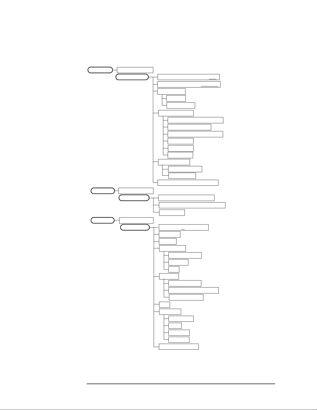
Figure 2-1 Mode Setup / Frequency Channel Key Flow
GSM or EDGE w/GSMMode
Mode Setup
Frequency Channel
Radio
Band P-GSM, E-GSM, R-GSM, DCS 1800, PCS 1900, GSM 450, GSM 480, GSM 850
Device BTS | MS
BTS Type Normal, Micro, Pico
Freq Hopping On |Off
Carrier Burst | Cont
Input
Input Port RF, I/Q, I only, 50 MHz Ref, IF Align
RF Input Range Auto| Man
Max Total Pwr
Input Atten
Ext Atten
MS 0.00 dB
BTS 0.00 dB
IF Align Signal
Signal Rate
Signal Amptd
Signal Type CW, Comb, Pulse
Trigger
RF Burst
Delay
Peak Level
Slope Pos| Neg
Video (IF Envlp)
Delay
Level
Slope Pos| Neg
Ext Front
Delay
Level
Slope Pos| Neg
Ext Rear
Delay
Level
Slope Pos| Neg
Trig Holdoff
Auto Trig 100.0 ms On | Off
Frame Timer
Period
Offset
Reset Offset Display
Sync Source Off, Ext Front, Ext Rear
RF Sync Delay
Burst SearchThreshold
Demod
Burst Align
GSM
1/2 Bit Offset
ARFCN
Center Freq
BTM Freq Top, Middle, Bottom
Timeslot On | Off
Burst Type Normal, Sync, Access
TSC (Std) 0 Auto | Man
<Available for RF only>
<Available for RF and 50 MHz Ref only>
<Auto not for Spectrum>
<for EVM when Device is MS>
Setting Up the GSM Mode
GSM Measurement Key Flow
Chapter 2 25

Setting Up the GSM Mode
GSM Measurement Key Flow
Figure 2-2 Transmit Power Measurement Key Flow
Measure
Transmit Pwr
Meas Setup
Transmit PwrMeasure
Marker
Averages 50 On | Off
Avg Mode Exp | Repeat
Avg Type
Pwr Avg (RMS)
Log-Pwr Avg (Video)
Maximum
Minimum
Threshold Lvl -6.00 dB Abs |Rel
Trig Source
Free Run (Immediate)
Video (IF Envlp)
RF Burst (Wideband)
Ext Front
Ext Rear
Frame
Burst Sync None
Meas Time 1 Slot
Restore Meas Defaults
Advanced
RBW Filter Gaussian | Flat
Res BW 500.000 kHz
Select 1 | 2 | 3 | 4
Normal
Delta
Function
Band Power
Noise
Off
Trace
RF Envelope
I/Q Waveform
Off
Shape
Diamond
Line
Square
Cross
Marker All Off
26 Chapter2

Figure 2-3 Power vs. Time Measurement Key Flow
Setting Up the GSM Mode
GSM Measurement Key Flow
Measure
Pwr vs Time
Meas Setup
Pwr vs TimeMeasure
View/Trace
Avg Bursts 10On | Off
Avg Mode Exp | Repeat
Avg Type
Pwr Avg (RMS)
Log-Pwr Avg (Video)
Maximum
Minimum
Meas Time 1 Slot
Trig Source
Free Run (Immediate)
Video (IF Envlp)
RF Burst (Wideband)
Ext Front
Ext Rear
Frame
Burst Sync
Training Seq
RF Amptd
Restore Meas Defaults
Advanced
RBW Filter Gaussian | Flat
Res BW 508.000 kHz
Burst
Rise & Fall
Pwr vs TimeMeasure
Marker
Select 1 | 2 | 3 | 4
Normal
Delta
Function
Band Power
Noise
Off
Trace
RF Envelope
Upper Mask
Lower Mask
Off
Shape
Diamond
Line
Square
Cross
Marker All Off
Chapter 2 27
Setting Up the GSM Mode
GSM Measurement Key Flow
Figure 2-4 Phase and Frequency Error Measurement Key Flow
Measure
Phase & Freq
Meas Setup
Phase & FreqMeasure
View/Trace
Phase & FreqMeasure
Marker
Avg Bursts 10On | Off
Avg Mode Exp | Repeat
Avg Type
Mean
Maximum
Trig Source
Free Run (Immediate)
Video (IF Envlp)
RF Burst (Wideband)
Ext Front
Ext Rear
Frame
Burst Sync
Training Seq
RF Amptd
Restore Meas Defaults
I/Q Error (Quad-View)
I/Q Measured Polar Vector
Data Bits
Select 1 | 2 | 3 | 4
Normal
Delta
Function
Band Power
Noise
Off
Trace
Phase Error
Phase Error w/Freq
RF Envelope
Off
Shape
Diamond
Line
Square
Cross
Marker All Off
28 Chapter2

Figure 2-5 Output RF Spectrum Measurement Key Flow
Setting Up the GSM Mode
GSM Measurement Key Flow
Measure
Output RF Spectrum
Meas Setup
Output RF SpectrumMeasure
View/Trace
Avg Bursts 20 On | Off
Avg Mode Exp | Repeat
Meas Method
Meas Type
Ofs Freq List
Fast Avg On Off
Restore Meas Defaults
Advanced
Modulation Numeric
Multi-Offset
Single Offset (Examine)
Mod & Switch
Modulation
Switching
Standard
Short
Custom
Mod Avg
Pwr Avg (RMS)
Log-Pwr Avg (Video)
Modulation Meas BWs
Carrier RBW 30.000 kHz
< 1800 kHz Offset RBW 30.000 kHz
>= 1800 kHz Offset RBW 100.000 kHz
Switching Meas BWs
Carrier RBW 300 kHz
< 1800 kHz Offset RBW 30.000 kHz
>= 1800 kHz Offset RBW 30.000 kHz
Direct Time Break Freq 600.000 kHz
Output RF SpectrumMeasure
Marker
Select 1 | 2 | 3 | 4
Normal
Delta
Function
Band Power
Noise
Off
Trace
RF Envelope Modulation
RF Envelope Switching
Off
Shape
Diamond
Line
Square
Cross
Marker All Off
Chapter 2 29
 Loading...