


W-CDMA Measurement Guide
Agilent Technologies E4406A VSA Series
Transmitter Tester
Manufacturing Part Number: E4406-90088
Printed in USA
April 2000
© Copyright 1999-2000 Agilent Technologies, Inc.

The information contained in this document is subject to change
without notice.
Agilent Technologiesmakesnowarrantyofanykindwithregard to this
material, including but not limited to, the implied warranties of
merchantability and fitness for a particular purpose. Agilent
Technologies shall not be liable for errors contained herein or for
incidental or consequential damages in connection with the furnishing,
performance, or use of this material.
2

1. Understanding W-CDMA
What Is the W-CDMA Communication System? . . . . . . . . . . . . . . . . . . . . . . . . . . . . . . . . . . . . 6
What Does the E4406A VSA Series Transmitter Tester Do? . . . . . . . . . . . . . . . . . . . . . . . . . . 7
Other Sources of Measurement Information . . . . . . . . . . . . . . . . . . . . . . . . . . . . . . . . . . . . . . . 8
Instrument Updates at www.agilent.com/find/vsa/. . . . . . . . . . . . . . . . . . . . . . . . . . . . . . . . . 8
2. Setting Up the W-CDMA Mode
W-CDMA Mode. . . . . . . . . . . . . . . . . . . . . . . . . . . . . . . . . . . . . . . . . . . . . . . . . . . . . . . . . . . . . . 10
How to Make a Measurement. . . . . . . . . . . . . . . . . . . . . . . . . . . . . . . . . . . . . . . . . . . . . . . . . 10
Changing the Mode Setup . . . . . . . . . . . . . . . . . . . . . . . . . . . . . . . . . . . . . . . . . . . . . . . . . . . 12
Changing the Frequency Channel . . . . . . . . . . . . . . . . . . . . . . . . . . . . . . . . . . . . . . . . . . . . . 17
W-CDMA Measurement Key Flow . . . . . . . . . . . . . . . . . . . . . . . . . . . . . . . . . . . . . . . . . . . . . . 18
Installing Optional
Measurement Personalities. . . . . . . . . . . . . . . . . . . . . . . . . . . . . . . . . . . . . . . . . . . . . . . . . . . .35
Available Options . . . . . . . . . . . . . . . . . . . . . . . . . . . . . . . . . . . . . . . . . . . . . . . . . . . . . . . . . . 36
License Key Numbers. . . . . . . . . . . . . . . . . . . . . . . . . . . . . . . . . . . . . . . . . . . . . . . . . . . . . . .36
Installing a License Key Number. . . . . . . . . . . . . . . . . . . . . . . . . . . . . . . . . . . . . . . . . . . . . . 37
Using the Uninstall Key. . . . . . . . . . . . . . . . . . . . . . . . . . . . . . . . . . . . . . . . . . . . . . . . . . . . .38
3. Making W-CDMA Measurements
W-CDMA Measurements . . . . . . . . . . . . . . . . . . . . . . . . . . . . . . . . . . . . . . . . . . . . . . . . . . . . . . 40
Preparing for Measurements. . . . . . . . . . . . . . . . . . . . . . . . . . . . . . . . . . . . . . . . . . . . . . . . . . . 41
Initial Setup. . . . . . . . . . . . . . . . . . . . . . . . . . . . . . . . . . . . . . . . . . . . . . . . . . . . . . . . . . . . . . . 41
Measurement Selection. . . . . . . . . . . . . . . . . . . . . . . . . . . . . . . . . . . . . . . . . . . . . . . . . . . . . .41
Measurement Control. . . . . . . . . . . . . . . . . . . . . . . . . . . . . . . . . . . . . . . . . . . . . . . . . . . . . . .43
Measurement Setup . . . . . . . . . . . . . . . . . . . . . . . . . . . . . . . . . . . . . . . . . . . . . . . . . . . . . . . .43
Making the Channel Power Measurement. . . . . . . . . . . . . . . . . . . . . . . . . . . . . . . . . . . . . . . . 46
Purpose . . . . . . . . . . . . . . . . . . . . . . . . . . . . . . . . . . . . . . . . . . . . . . . . . . . . . . . . . . . . . . . . . . 46
Measurement Method. . . . . . . . . . . . . . . . . . . . . . . . . . . . . . . . . . . . . . . . . . . . . . . . . . . . . . . 46
Making the Measurement . . . . . . . . . . . . . . . . . . . . . . . . . . . . . . . . . . . . . . . . . . . . . . . . . . . 47
Results. . . . . . . . . . . . . . . . . . . . . . . . . . . . . . . . . . . . . . . . . . . . . . . . . . . . . . . . . . . . . . . . . . . 47
Changing the Measurement Setup . . . . . . . . . . . . . . . . . . . . . . . . . . . . . . . . . . . . . . . . . . . . 48
Changing the Display . . . . . . . . . . . . . . . . . . . . . . . . . . . . . . . . . . . . . . . . . . . . . . . . . . . . . . .50
Troubleshooting Hints . . . . . . . . . . . . . . . . . . . . . . . . . . . . . . . . . . . . . . . . . . . . . . . . . . . . . .51
Making the Adjacent Channel Power Ratio (ACPR) Measurement . . . . . . . . . . . . . . . . . . . . 52
Purpose . . . . . . . . . . . . . . . . . . . . . . . . . . . . . . . . . . . . . . . . . . . . . . . . . . . . . . . . . . . . . . . . . . 52
Measurement Method. . . . . . . . . . . . . . . . . . . . . . . . . . . . . . . . . . . . . . . . . . . . . . . . . . . . . . . 52
Making the Measurement . . . . . . . . . . . . . . . . . . . . . . . . . . . . . . . . . . . . . . . . . . . . . . . . . . . 53
Results. . . . . . . . . . . . . . . . . . . . . . . . . . . . . . . . . . . . . . . . . . . . . . . . . . . . . . . . . . . . . . . . . . . 53
Changing the Measurement Setup . . . . . . . . . . . . . . . . . . . . . . . . . . . . . . . . . . . . . . . . . . . . 54
Changing the View . . . . . . . . . . . . . . . . . . . . . . . . . . . . . . . . . . . . . . . . . . . . . . . . . . . . . . . . . 57
Changing the Display . . . . . . . . . . . . . . . . . . . . . . . . . . . . . . . . . . . . . . . . . . . . . . . . . . . . . . .58
Troubleshooting Hints . . . . . . . . . . . . . . . . . . . . . . . . . . . . . . . . . . . . . . . . . . . . . . . . . . . . . .59
Making the Power Stat CCDF Measurement. . . . . . . . . . . . . . . . . . . . . . . . . . . . . . . . . . . . . . 60
Purpose . . . . . . . . . . . . . . . . . . . . . . . . . . . . . . . . . . . . . . . . . . . . . . . . . . . . . . . . . . . . . . . . . . 60
Measurement Method. . . . . . . . . . . . . . . . . . . . . . . . . . . . . . . . . . . . . . . . . . . . . . . . . . . . . . . 60
Making the Measurement . . . . . . . . . . . . . . . . . . . . . . . . . . . . . . . . . . . . . . . . . . . . . . . . . . . 61
Results. . . . . . . . . . . . . . . . . . . . . . . . . . . . . . . . . . . . . . . . . . . . . . . . . . . . . . . . . . . . . . . . . . . 61
Changing the Measurement Setup . . . . . . . . . . . . . . . . . . . . . . . . . . . . . . . . . . . . . . . . . . . . 62
Changing the View . . . . . . . . . . . . . . . . . . . . . . . . . . . . . . . . . . . . . . . . . . . . . . . . . . . . . . . . . 62
Changing the Display . . . . . . . . . . . . . . . . . . . . . . . . . . . . . . . . . . . . . . . . . . . . . . . . . . . . . . .63
Using the Markers . . . . . . . . . . . . . . . . . . . . . . . . . . . . . . . . . . . . . . . . . . . . . . . . . . . . . . . . . 63
Troubleshooting Hints . . . . . . . . . . . . . . . . . . . . . . . . . . . . . . . . . . . . . . . . . . . . . . . . . . . . . .64
Contents
3

Contents
Making the Code Domain Measurement . . . . . . . . . . . . . . . . . . . . . . . . . . . . . . . . . . . . . . . . . .65
Purpose . . . . . . . . . . . . . . . . . . . . . . . . . . . . . . . . . . . . . . . . . . . . . . . . . . . . . . . . . . . . . . . . . .65
Measurement Method . . . . . . . . . . . . . . . . . . . . . . . . . . . . . . . . . . . . . . . . . . . . . . . . . . . . . . .65
Making the Measurement . . . . . . . . . . . . . . . . . . . . . . . . . . . . . . . . . . . . . . . . . . . . . . . . . . . .67
Results . . . . . . . . . . . . . . . . . . . . . . . . . . . . . . . . . . . . . . . . . . . . . . . . . . . . . . . . . . . . . . . . . . .67
Changing the Measurement Setup . . . . . . . . . . . . . . . . . . . . . . . . . . . . . . . . . . . . . . . . . . . . .68
Changing the View. . . . . . . . . . . . . . . . . . . . . . . . . . . . . . . . . . . . . . . . . . . . . . . . . . . . . . . . . .71
Changing the Display. . . . . . . . . . . . . . . . . . . . . . . . . . . . . . . . . . . . . . . . . . . . . . . . . . . . . . . .73
Using the Markers . . . . . . . . . . . . . . . . . . . . . . . . . . . . . . . . . . . . . . . . . . . . . . . . . . . . . . . . . .77
Troubleshooting Hints . . . . . . . . . . . . . . . . . . . . . . . . . . . . . . . . . . . . . . . . . . . . . . . . . . . . . . .78
Making the QPSK EVM Measurement . . . . . . . . . . . . . . . . . . . . . . . . . . . . . . . . . . . . . . . . . . .79
Purpose . . . . . . . . . . . . . . . . . . . . . . . . . . . . . . . . . . . . . . . . . . . . . . . . . . . . . . . . . . . . . . . . . . .79
Measurement Method . . . . . . . . . . . . . . . . . . . . . . . . . . . . . . . . . . . . . . . . . . . . . . . . . . . . . . .79
Making the Measurement . . . . . . . . . . . . . . . . . . . . . . . . . . . . . . . . . . . . . . . . . . . . . . . . . . . .80
Results . . . . . . . . . . . . . . . . . . . . . . . . . . . . . . . . . . . . . . . . . . . . . . . . . . . . . . . . . . . . . . . . . . .80
Changing the Measurement Setup . . . . . . . . . . . . . . . . . . . . . . . . . . . . . . . . . . . . . . . . . . . . .81
Changing the View. . . . . . . . . . . . . . . . . . . . . . . . . . . . . . . . . . . . . . . . . . . . . . . . . . . . . . . . . .82
Changing the Display. . . . . . . . . . . . . . . . . . . . . . . . . . . . . . . . . . . . . . . . . . . . . . . . . . . . . . . .83
Using the Markers . . . . . . . . . . . . . . . . . . . . . . . . . . . . . . . . . . . . . . . . . . . . . . . . . . . . . . . . . .86
Troubleshooting Hints . . . . . . . . . . . . . . . . . . . . . . . . . . . . . . . . . . . . . . . . . . . . . . . . . . . . . . .86
Making the Modulation Accuracy (Rho) Measurement. . . . . . . . . . . . . . . . . . . . . . . . . . . . . . .87
Purpose . . . . . . . . . . . . . . . . . . . . . . . . . . . . . . . . . . . . . . . . . . . . . . . . . . . . . . . . . . . . . . . . . .87
Measurement Method . . . . . . . . . . . . . . . . . . . . . . . . . . . . . . . . . . . . . . . . . . . . . . . . . . . . . . .87
Making the Measurement . . . . . . . . . . . . . . . . . . . . . . . . . . . . . . . . . . . . . . . . . . . . . . . . . . . .88
Results . . . . . . . . . . . . . . . . . . . . . . . . . . . . . . . . . . . . . . . . . . . . . . . . . . . . . . . . . . . . . . . . . . .88
Changing the Measurement Setup . . . . . . . . . . . . . . . . . . . . . . . . . . . . . . . . . . . . . . . . . . . . .89
Changing the View. . . . . . . . . . . . . . . . . . . . . . . . . . . . . . . . . . . . . . . . . . . . . . . . . . . . . . . . . .90
Changing the Display. . . . . . . . . . . . . . . . . . . . . . . . . . . . . . . . . . . . . . . . . . . . . . . . . . . . . . . .91
Using the Markers . . . . . . . . . . . . . . . . . . . . . . . . . . . . . . . . . . . . . . . . . . . . . . . . . . . . . . . . . .94
Troubleshooting Hints . . . . . . . . . . . . . . . . . . . . . . . . . . . . . . . . . . . . . . . . . . . . . . . . . . . . . . .94
Making the Spectrum (Frequency Domain) Measurement. . . . . . . . . . . . . . . . . . . . . . . . . . . .95
Purpose . . . . . . . . . . . . . . . . . . . . . . . . . . . . . . . . . . . . . . . . . . . . . . . . . . . . . . . . . . . . . . . . . .95
Measurement Method . . . . . . . . . . . . . . . . . . . . . . . . . . . . . . . . . . . . . . . . . . . . . . . . . . . . . . .95
Making the Measurement . . . . . . . . . . . . . . . . . . . . . . . . . . . . . . . . . . . . . . . . . . . . . . . . . . . .95
Results . . . . . . . . . . . . . . . . . . . . . . . . . . . . . . . . . . . . . . . . . . . . . . . . . . . . . . . . . . . . . . . . . . .96
Changing the Measurement Setup . . . . . . . . . . . . . . . . . . . . . . . . . . . . . . . . . . . . . . . . . . . . .97
Changing the View . . . . . . . . . . . . . . . . . . . . . . . . . . . . . . . . . . . . . . . . . . . . . . . . . . . . . . . .101
Using the Markers . . . . . . . . . . . . . . . . . . . . . . . . . . . . . . . . . . . . . . . . . . . . . . . . . . . . . . . . .101
Troubleshooting Hints . . . . . . . . . . . . . . . . . . . . . . . . . . . . . . . . . . . . . . . . . . . . . . . . . . . . . .102
Making the Waveform (Time Domain) Measurement . . . . . . . . . . . . . . . . . . . . . . . . . . . . . . .103
Purpose . . . . . . . . . . . . . . . . . . . . . . . . . . . . . . . . . . . . . . . . . . . . . . . . . . . . . . . . . . . . . . . . .103
Measurement Method . . . . . . . . . . . . . . . . . . . . . . . . . . . . . . . . . . . . . . . . . . . . . . . . . . . . . .103
Making the Measurement . . . . . . . . . . . . . . . . . . . . . . . . . . . . . . . . . . . . . . . . . . . . . . . . . . .104
Results . . . . . . . . . . . . . . . . . . . . . . . . . . . . . . . . . . . . . . . . . . . . . . . . . . . . . . . . . . . . . . . . . .104
Changing the Measurement Setup . . . . . . . . . . . . . . . . . . . . . . . . . . . . . . . . . . . . . . . . . . . .105
Changing the View . . . . . . . . . . . . . . . . . . . . . . . . . . . . . . . . . . . . . . . . . . . . . . . . . . . . . . . .107
Using the Markers . . . . . . . . . . . . . . . . . . . . . . . . . . . . . . . . . . . . . . . . . . . . . . . . . . . . . . . . .108
Troubleshooting Hints . . . . . . . . . . . . . . . . . . . . . . . . . . . . . . . . . . . . . . . . . . . . . . . . . . . . . .108
4

1 Understanding W-CDMA
5

Understanding W-CDMA
What Is the W-CDMA Communication System?
What Is the W-CDMA Communication System?
Wideband code division multiple access (W-CDMA) is one of the popular
air interface technologies for the third generation RF cellular
communications systems. In this system, the cells operate
asynchronously, hence it makes the mobile synchronization more
complex, but offers the advantage of flexibility in placement of the base
stations. Both reverse and forward transmitter power controls are
implemented with 0.625 ms intervals. W-CDMA is a direct sequence
spread-spectrum digital communications techniquethatsupportswider
RF bandwidths, typically from 5 to 20 MHz. The main advantages of
W-CDMA over other types of communication schemes are:
• greater capacity
• immunity to signal loss and degradation in the presence of
high-level broadband interference
• immunity to signal loss and degradation due to multipath,
scattering, and fading
• power consumption of mobile stations is strictly minimized by both
base station and mobile controls
• supports variable data rates up to 144 kbits/second for mobile
(vehicular) data rate,up to 384 kbits/second for portable (pedestrian)
data rate, and up to 2 Mbits/second for fixed installations
• provides increased security
W-CDMA uses correlative codes to distinguish one user from another.
Frequency division is still used, as is done with Frequency Division
Multiple Access (FDMA) and Time Division Multiple Access (TDMA),
but in a much larger bandwidth such as 5 MHz or greater. An initial
baseband data rate is spread to a transmitted bit rate of 4.096 Mcps,
which is also called chip rate or spread data rate. W-CDMA realizes
increased capacity from 1:1 frequency reuse and sectored cells. The
capacity limit is soft. That is, capacity can be increased with some
degradation of the error rate or voice quality.
In W-CDMA, a single user's channel consists of a specific frequency
combined with a unique code. Correlative codes allow each user to
operate in the presence of substantial interference. The interference is
the sum of all other users on the same W-CDMA frequency, both from
within and outside of the home cell, and from delayed versions of these
signals. It also includes the usual thermal noise and atmospheric
disturbances. Delayed signals caused by multipath are separately
received and combined in W-CDMA. One of the major differences in
access is that any W-CDMA frequency can be used in all sectors of all
cells.This is possible because W-CDMA is designed to decode the proper
signal in the presence of high interference.
6 Chapter1

Understanding W-CDMA
What Does the Agilent Technologies E4406A VSA Series Transmitter Tester
Do?
What Does the Agilent Technologies E4406A VSA Series Transmitter Tester Do?
This instrument can help determine if a W-CDMA transmitter is
working correctly. When configured for W-CDMA, the instrument can
be used for the testing of a W-CDMA transmitter, according to
documents such as ARIB 1.0-1.2, Trial 1998 (the trial W-CDMA system
originated in Japan), and 3GPP (3rd Generation Partnership Project).
These documents define complex, multi-part measurements used to
maintain an interference-free environment. For example, the
documents include measuring the power of a carrier.
The E4406A Transmitter Tester automatically makes these
measurements using the measurement methods and limits defined in
the documents. The detailed results displayed by the measurements
allow you to analyze W-CDMA system performance. You may alter the
measurement parameters for specialized analysis.
For infrastructure test, the instrument will test base station
transmitters in a non-interfering manner by means of a coupler or
power splitter.
This instrument makes the following measurements:
• Channel Power
• Adjacent Channel Power Ratio (ACPR)
• Power Statistics CCDF
• Code Domain
• QPSK EVM
• Modulation Accuracy (Rho)
• Spectrum (Frequency Domain)
• Waveform (Time Domain)
Chapter 1 7

Understanding W-CDMA
Other Sources of Measurement Information
Other Sources of Measurement Information
Additional measurement application information is available through
your local Agilent Technologies sales and service office. The following
application notes treat digital communications measurements in much
greater detail than discussed in this measurement guide.
• Application Note 1298
Digital Modulation in Communications Systems - An Introduction
part number 5965-7160E
• Application Note 1311
Understanding CDMA Measurements for Base Stations and Their
Components
part number 5968-0953E
Instrument Updates at www.agilent.com/find/vsa/
This web location can be used to access the latest information about the
transmitter tester.
8 Chapter1

2 Setting Up the W-CDMA Mode
9

Setting Up the W-CDMA Mode
W-CDMA Mode
W-CDMA Mode
You may want to install a new personality, reinstall a personality that
you have previously uninstalled, or uninstall a personality. Instructions
for installing and uninstalling personality options are under “Installing
Optional Measurement Personalities” on page 35.
At initial power up, the transmitter tester will come up in the Basic
mode, with the Spectrum (frequency domain) measurement selected
and the
Measure menu displayed.
To access the W-CDMA measurement personality, press the
and select the
W-CDMA key.
If you want to set the W-CDMA mode to a known, factory default state,
press Preset. This will preset the mode setup and all of the
measurements to the factory default parameters.
NOTE Pressing the Preset key does not switch instrument modes.
How to Make a Measurement
Follow the three-step procedure shown in the table below:
Step Primary Key Setup Key Related Key
1. Select & setup
a mode.
2. Select & setup
a measurement.
3. Select & setup
a view.
Mode Mode Setup, Input,
Frequency Channel
Measure Meas Setup Meas Control,
View/Trace Span X Scale,
Amplitude Y Scale,
Display, Next Window,
Zoom
System
Restart
File, Save,
Print, Print Setup,
Marker, Search
Mode key
Step 1. Select & setup a mode as follows, for example:
• Press the
• Press the
Mode key and select W-CDMA.
Frequency Channel key and enter the channel frequency to
be measured.
• Press the
Mode Setup key and change the Radio, Input, and Trigger
conditions from those default settings.
Refer to “Changing the Mode Setup” on page 12 and “Changing the
Frequency Channel” on page 17 for further explanation.
10 Chapter2

Setting Up the W-CDMA Mode
Refer to “Mode Setup / Frequency Channel Key Flow” on page 19 for the
key flow diagrams.
Step 2. Select & setup a measurement as follows, for example:
• Press the Measure key to select either Channel Power, ACPR, Power
Stat CCDF, Code Domain, Spectrum (Freq Domain), Waveform (Time
Domain), QPSK EVM, or Mod Accuracy (Perch Only) to make its
measurement.
W-CDMA Mode
• Press the
Meas Setup key to change any of the measurement
parameters from the default settings. These parameters such as
Span, Resolution Bandwidth, Trigger Source, Average, Limit Test
and Limits, are decided according to the measurement selected.
Refer to “Channel Power Measurement Key Flow” on page 20 and to
“Waveform (Time Domain) Measurement Key Flow (1 of 2)” on page 33
for the key flow diagrams.
Step 3. Select & setup a view as follows, for example:
• Press the
View/Trace key to select the desired view for the current
measurement.
• Press the
Next Window key to select a window, then press the Zoom
key to expand the window to the full display area.
• Press the
Span X Scale, Amplitude Y Scale, Display, and/or Marker keys
for your desired display. These keys are not always availablefor each
view.
Refer to “Channel Power Measurement Key Flow” on page 20 and to
“Waveform (Time Domain) Measurement Key Flow (1 of 2)” on page 33
for the key flow diagrams.
Entering a Numeric Value
Three methods are available to enter a numeric value for an active
softkey, however, its resolution can be different depending on the
method selected and the range, if any. The highest resolutions are
described throughout this guide.
•
Numeric keys - Allows you to enter a value with the highest
resolution by pressing the numeric keys. The entry is terminated by
pressing the
Enter key or one of the unit softkeys shown.
• RPG knob - Allows you to continuously change the value shown on
the softkey with the medium or highest resolution defined to the
parameter by rotating this knob.
• Step (Up/Down arrow) keys - Allows you to change the value shown on
the softkey with the fixed-step resolution defined to the parameter
activated. While the ⇑ (up arrow) key is pressed down, for example,
the value increases in multiple steps defined to the parameter.
Chapter 2 11

Setting Up the W-CDMA Mode
W-CDMA Mode
Changing the Mode Setup
Numerous settings can be changed at the mode level by pressing the
Mode Setup key. This will access the menu with the selections listed
below. The factory default settings are shown in tables. These settings
affect only the measurements in the W-CDMA mode.
Configuring the Radio Setting
The
Radio key accesses the menu as follows:
Device - Allows you to toggle the test device between BTS (Base
•
Transmission Station) and
MS-BTS Offset - Allows you to specify the frequency space between
•
MS and BTS. The range is −500.000 MHz to 500.000 MHz with
1 kHz resolution.
•
Standard - Allows you to access the menu to select one of the
standards as follows:
ARIB 1.0-1.2 - Allows you to make measurements compliant to the
ARIB 1.0-1.2 document submitted to 3GPP.
MS (Mobile Station).
3GPP - Allows you to make measurements compliant to the
evolving third generation partnership project document.
Trial 1998 - Allows you to make measurements compliant to the
W-CDMA trial system that originated in Japan.
Radio Default Settings
Device BTS
MS-BTS Offset 190.000 MHz
Standard Trial 1998
Configuring the Input Setting
The
Input key accesses the menu as follows: (You can also access this
menu from the
RF Input Range - Allows you to toggle the RF input range control
•
between
Input front-panel key.)
Auto and Man (manual). If Auto is chosen, the instrument
automatically sets the attenuator based on the carrier power level,
where it is tuned. Once you change the
Max Total Pwr or Input Atten
value with the RPG knob, for example, the RF Input Range key is
automatically set to
Man. If there are multiple carriers present, the
total power might overdrive the front end. In this case you need to
set the
power by activating the
RF Input Range to Man and enter the expected maximum total
Max Total Pwr key. Man is also useful to hold
the input attenuation constant for the best relative power accuracy.
For single carriers it is generally recommended to set this to
Auto.
12 Chapter2

Setting Up the W-CDMA Mode
W-CDMA Mode
• Max TotalPwr - Allows you to set the maximum total power level from
the UUT (Unit Under Test). The range is −200.00 to 100.00 dBm
with 0.01 dB resolution. This is the expected maximum value of the
mean carrier power referenced to the output of the UUT; it may
include multiple carriers. The
together with the
the
Max Total Pwr value with the RPG knob, for example, the RF Input
Range key is automatically set to Man.
Input Atten - Allows you to control the internal input attenuator
•
Input Atten and Ext Atten settings. Once you change
setting. The range is 0 to 40 dB with 1 dB resolution. The
Max Total Pwr setting is coupled
Input Atten
key reads out the actual hardware value that is used for the current
measurement. If more than one input attenuator value is used in a
single measurement, the value used at the carrier frequency will be
displayed. The
Input Atten setting is coupled to the Max Total Pwr
setting. Once you change the Input Atten setting with the RPG knob,
for example, the
Ext Atten - Allows you to access the following menu to enter the
•
external attenuation values. Either of the
coupled together with the
Ext Atten does not switch the RF Input Range key to Man. This will
RF Input Range key is automatically set to Man.
Ext Atten settings is
RF Input Range setting, however, pressing
allow the instrument to display the measurement results referenced
to the output of the UUT.
MS - Allows you to set an external attenuation value for MS tests.
The range is −50.00 to +50.00 dB with 0.01 dB resolution.
BTS - Allows you to set an external attenuation value for BTS
tests. The range is −50.00 to +50.00 dB with 0.01 dB resolution.
Input Default Settings
RF Input Range
Max Total Pwr
Input Atten
Ext Atten:
MS
BTS
a
Auto
−15.00 dBm
0.00 dB
0.00 dB
0.00 dB
b
b
a. Auto is not used for Spectrum measurements.
b. This may differ if the maximum input power is
more than −15.00 dBm, or depending on the
previous measurements.
Chapter 2 13

Setting Up the W-CDMA Mode
W-CDMA Mode
NOTE The Max Total Pwr and the Input Atten settings are coupled together.
When you switch to a different measurement, the
is kept constant, but the
Input Atten setting may change if the two
Max Total Pwr setting
measurements have different mixer margins.Thus,you can directly set
the transmitter tester input attenuator, or you can set it indirectly by
specifying the expected maximum power at the UUT (Max Total Pwr
setting).
Configuring the Trigger Condition
Trigger key allows you: (1) to access the trigger selection menu to
The
specify each triggering condition, (2) to modify the default trigger
holdoff time using the
Trig Holdoff key, (3) to modify the auto trigger
time and to activate or deactivate the auto trigger feature using the
Auto Trig key, and (4) to modify the period of the frame timer using the
Frame Timer key.
NOTE The actual trigger source is selected separately for each measurement
under the Meas Setup key.
•
RF Burst, Video (IF Envlp), Ext Front and Ext Rear - Pressing one of
these trigger keys will access each triggering condition setup menu.
This menu is used to specify the
Delay, Level and Slope settings for
each trigger source as follows:
Delay - Allows you to enter a numerical value to modify the
trigger delay time. The range is −100.0 to +500.0 ms with 1 µs
resolution. For trigger delay use a positive value, and for
pre-trigger use a negative value.
Level - Allows you to enter a numerical value to adjust the trigger
level depending on the trigger source selected.
For
RF Burst selection, the key label reads as Peak Level. The
RF level range is −25.00 to 0.00 dB with 0.01 dB resolution,
relative to the peak RF signal level. The realistic range can be
down to −20 dB.
For
Video (IF Envlp) selection, the video level range is −200.00
to +50.00 dBm with 0.01 dB resolution at the RF input. The
realistic range can be down to around −50 dBm depending on
the noise floor level of the input signal.
For
Ext Front or Ext Rear selection, the level range is −5.00 to
+5.00 V with 1 or 10 mV resolution.
Slope - Allows you to toggle the trigger slope between Pos at the
positive-going edge and
Neg at the negative-going edge of the
burst signal.
There are other keys under the Trigger key as follows:
14 Chapter2

Setting Up the W-CDMA Mode
W-CDMA Mode
• Trig Holdoff - Allows you to set the period of time before the next
trigger can occur. The range is 0.000 µs to 500.0 ms with 1 µs
resolution.
•
Auto Trig - Allows you to specify a time for a trigger timeout and
toggle the auto trigger function between
On and Off. The range is
1.000 ms to 1.000 ks with 1 µs resolution. If no trigger occurs by the
specified time, a trigger is automatically generated.
•
Frame Timer - Allows you to access the menu to manually control the
frame timer:
Period - Allows you to set the period of the frame clock. The range
is 0.000 ns to 559.0000 ms with 1 ps resolution.
Offset - Allows you to set the offset of the frame clock. The range
is 0.000 to 10.00 s with 100 ns resolution over 1.000 µs range.
Reset Offset Display - Allows you to display without any offset of
the frame clock.
Sync Source - Allows you to access the menu to select one of the
sources to be synchronized with.
Off - Allows you to turn the synchronizing source off for
asynchronous tests.
RF Burst (Wideband) - Allows you to select the RF burst signal
as the synchronizing source.
Ext Front - Allows you to select the external input signal from
the front-panel input port as the synchronizing source.
Ext Rear - Allows you to select the external input signal from
the rear panel input port as the synchronizing source.
Chapter 2 15

Setting Up the W-CDMA Mode
W-CDMA Mode
Trigger Default Settings
RF Burst:
Delay
Peak Level
Slope
Video (IF Envlp):
Delay
Level
Slope
Ext Front:
Delay
Level
Slope
Ext Rear:
Delay
Level
Slope
0.000 µs
−6.00 dB
Pos
0.000 µs
−6.00 dBm
Pos
0.000 µs
2.00 V
Pos
0.000 µs
2.00 V
Pos
Trig Holdoff 0.000 ms
Auto Trig 100.0 ms, On
Frame Timer:
Period
Offset
Sync Source
10.00000 ms
0.000 ms
Off
16 Chapter2

Setting Up the W-CDMA Mode
W-CDMA Mode
Changing the Frequency Channel
After selecting the desired mode setup, you will need to select the
desired center frequency and the center frequency step. The selections
made here will apply to all measurements in the mode. Press the
Frequency Channel key to access the following menu:
Center Freq - Allows you to enter a frequency that corresponds to the
•
desired RF channel to be measured. This is the current instrument
center frequency. The range is 1.000 kHz to 4.32140 GHz with 1 Hz
resolution.
•
CF Step - Allows you to enter a center frequency step to shift the
measurement segment, and to toggle the step function between
and Man. If set to Auto, the CF Step value automatically changes
according to the selection of the standard. The range is 1.000 kHz to
1.00000 GHz with 1 Hz resolution.
Frequency Channel Default Settings
Frequency Channel:
Center Freq
CF Step
1.00000 GHz
5.00000 MHz, Auto
Auto
Chapter 2 17

Setting Up the W-CDMA Mode
W-CDMA Measurement Key Flow
W-CDMA Measurement Key Flow
The key flow diagrams, shown in a hierarchical manner on the
following pages, will help grasp the overall functional relationships for
the front-panel keys and the softkeys displayed at the extreme right
side of the screen. The diagrams are:
“Mode Setup / Frequency Channel Key Flow” on page 19,
“Channel Power Measurement Key Flow” on page 20,
“ACPR Measurement Key Flow” on page 21,
“Power Stat CCDF Measurement Key Flow” on page 22
“Code Domain Measurement Key Flow (1 of 3)” on page 23
“QPSK EVM Measurement Key Flow (1 of 2)” on page 26
“Modulation Accuracy Measurement Key Flow (1 of 2)” on page 28
View/Trace
QPSK EVM
<for EVM>
Avg Number 10 On|Off
“Spectrum (Freq Domain) Measurement Key Flow (1 of 3)” on page
30
“Waveform (Time Domain) Measurement Key Flow (1 of 2)” on page
33
Use these flow diagrams as follows:
• There are some basic conventions:
An oval represents one of the front-panel keys.
This box represents one of the softkeys displayed.
This represents an explanatory description on its specific key.
This box shows how the softkey default condition is displayed.
Default parameters or values are underlined wherever possible.
• Start from the extreme upper left corner of each measurement
diagram to the right direction, and go from the top to the bottom.
• When defining a key from auto with underline to manual, for
example, just press that key one time.
• When entering a numeric value of
Frequency, for example, use the
numeric keypad by terminating with the appropriate unit selection
from the softkeys displayed.
• When entering a numeric value of
numeric keypad by terminating with the
Avg Number, for example, use the
Enter front-panel key.
• Instead of using the numeric keypad to enter a value, it may be
easier to use the RPG knob or Up/Down keys depending on the input
field of a parameter.
18 Chapter2

Setting Up the W-CDMA Mode
W-CDMA Measurement Key Flow
Figure 2-1 Mode Setup / Frequency Channel Key Flow
W-CDMAMode
Mode Setup
Radio
Device BTS|MS
MS-BTS Offset 190.000 MHz
Standard Trial 1998
ARIB 1.0-1.2
3GPP
Trial 1998
Input
RF Input Range Auto|Man
Max Total Pwr -15.00 dBm
Input Atten 0.00 dB
Ext Atten
MS 0.00 dB
BTS 0.00 dB
Trigger
RF Burst
Delay 0.000 us
Peak Level -6.00 dB
Slope Pos|Neg
Video (IF Envlp)
Delay 0.000 us
Level -6.00 dBm
Slope Pos|Neg
Ext Front
Delay 0.000 us
Level 2.00 V
Slope Pos|Neg
Ext Rear
Delay 0.000 us
Level 2.00 V
Slope Pos|Neg
Trig Holdoff 0.000 ms
Auto Trig 100.0 ms On|Off
Frame Timer
Period 10.00000 ms
Offset 0.000 ms
Reset Offset Display
Sync Source
Off
RF Burst (Wideband)
Ext Front
Ext Rear
<Auto not for Spectrum>
Frequency Channel
Center Freq 1.00000 GHz
CF Step 5.00000 MHz Auto|Man
<wcd_mode.vsd>
Chapter 2 19

Setting Up the W-CDMA Mode
W-CDMA Measurement Key Flow
Figure 2-2 Channel Power Measurement Key Flow
Measure
Channel Power
Meas Setup
Channel PowerMeasure
Amplitude Y Scale
Avg Number 10 On|Off
Avg ModeExp| Repeat
Integ BW 5.00000 MHz
Chan Power Span 6.00000 MHz
Restore Meas Defaults
Advanced
Sweep Time 17.07 us Auto |Man
Data Points 512 Auto|Man
Res BW 111.429 kHz
Trig Source Free Run (Immediate)
Free Run (Immediate)
Ext Front
Ext Rear
Scale/Div 10.00 dB
Ref Value 10.00 dBm
Ref Position Top |Ctr|Bot
Scale CouplingOn|Off
<information only>
<wcd_chpj.vsd>
20 Chapter2
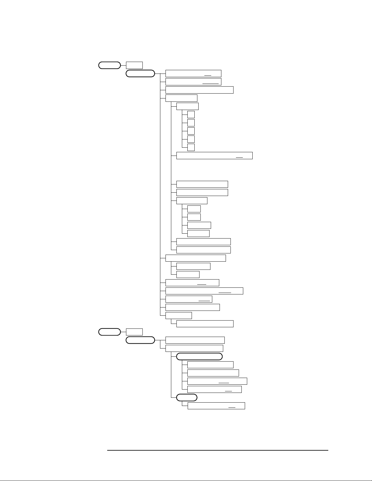
Figure 2-3 ACPR Measurement Key Flow
Setting Up the W-CDMA Mode
W-CDMA Measurement Key Flow
Measure
ACPR
Meas Setup
ACPRMeasure
View/Trace
Avg Number 10 On|Off
Avg ModeExp| Repeat
Chan Integ BW 4.09600 MHz
Ofs & Limits
Offset A
A
B
C
D
E
Offset Freq 5.00000 MHz On|Off
Ref BW 4.09600 MHz
Abs Limit 50.00 dBm
Fail Relative
AND
OR
Absolute
Relative
Rel Lim (Car) 0.00 dBc
Rel Lim (PSD) 0.00 dB <default for A to E: 0.0 dB>
Meas Type Total Pwr Ref
Total Pwr Ref
PSD Ref
Sweep Type FFT|Swp
Swp RBW 41.667 kHz Auto|Man
Swp Det Avg|Peak
Restore Meas Defaults
Advanced
Swp Acq Time 625.0 us
Bar Graph Total Pwr Ref
Spectrum Total Pwr Ref
Amplitude Y Scale
Scale/Div 10.00 dB
Ref Value 10.00 dBm
Ref Position Top |Ctr|Bot
Scale CouplingOn|Off
Display
Ref BW Markers On|Off
<default selection: A>
<default: A = 5.0 MHz, On
B = 10.0 MHz, On
C = 15.0 MHz, Off
D = 20.0 MHz, Off
E = 25.0 MHz, Off>
<default for A to E: 4.096 MHz>
<default for A to E: 50.0 dBm>
<default for A to E>
<default for A to E: 0.0 dBc>
<if Sweep Type = Swp>
<if Sweep Type = Swp>
<if Sweep Type = Swp>
<if Sweep Type = FFT>
<if Sweep Type = Swp>
<wcd_acpj.vsd>
Chapter 2 21

Setting Up the W-CDMA Mode
W-CDMA Measurement Key Flow
Figure 2-4 Power Stat CCDF Measurement Key Flow
Measure
Power Stat CCDF
Meas Setup
Power Stat CCDFMeasure
Span X Scale Scale/Div 2.00 dB
Power Stat CCDFMeasure
Display
Power Stat CCDFMeasure
Marker
Meas BW 5.00000 MHz
Counts 10.0000 Mpoints
Meas Interval 1.000 ms
Trig Source Free Run (Immediate)
Free Run (Immediate)
Video (IF Envlp)
RF Burst (Wideband)
Ext Front
Ext Rear
Frame
Restore Meas Defaults
Store Ref Trace
Ref Trace On|Off
Gaussian Line On|Off
Select 1|2|3|4
Normal
Delta
Function Off
Band Power
Noise
Off
Trace Measured
Measured
Gaussian
Reference
Off
Shape Diamond
Diamond
Line
Square
Cross
Marker All Off
<not available>
<not available>
<wcd_cdfj.vsd>
22 Chapter2

Setting Up the W-CDMA Mode
W-CDMA Measurement Key Flow
Figure 2-5 Code Domain Measurement Key Flow (1 of 3)
Measure
Code Domain
Meas Setup
Code DomainMeasure
View/Trace
<for ARIB & Trial 1998 BTS tests>
Symbol Rate 16 ksps
Code Number 0
Meas Interval 1 slots
Meas Offset 0 slots
Scramble Code 1
A
:
F
Done
Trig Source Free Run (Immediate)
Free Run (Immediate)
Video (IF Envlp)
RF Burst (Wideband)
Ext Front
Ext Rear
Frame
Spectrum Normal|Invert
Restore Meas Defaults
Advanced
Power Offset
Alpha 0.220
Chip Rate 4.09600 MHz
Power Graph & Metrics
Span X Scale
Ref Value 0.000
Ref Position Left|Ctr|Right
Amplitude Y Scale
<to enter a hexadecimal value>
Ref Set Auto|Man
PO1 (Pilot) 0.00 dB
PO2 (TPC) 0.00 dB
PO3 (TFCI) 0.00 dB
Scale/Div 511.0
Expand On|Off
Scale/Div 5.00 dB
Ref Value 0.00 dB
Ref Position Top |Ctr|Bot
Scale CouplingOn|Off
<for symbol EVM>
<for symbol EVM>
<for ARIB 1.0-1.2>
(a)
<wcd_cdp1.vsd>
Chapter 2 23

Setting Up the W-CDMA Mode
W-CDMA Measurement Key Flow
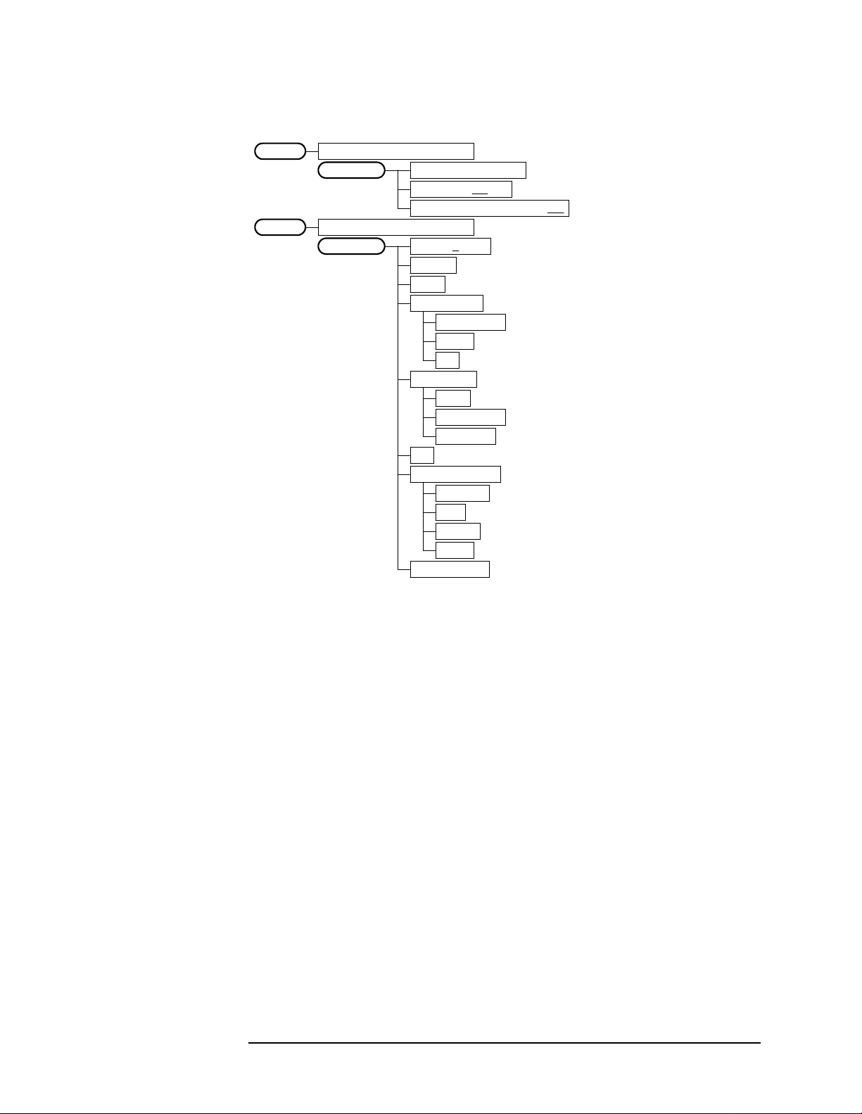
Figure 2-6 Code Domain Measurement Key Flow (2 of 3)
(a)
I/Q Error (Quad View)
Span X Scale
Scale/Div 1.900 symb
Ref Value 0.000 symb
Ref Position Left|Ctr|Right
Scale CouplingOn|Off
Amplitude Y Scale
Scale/Div 5.00 pcnt
Ref Value 0.00 pcnt
Ref Position Top|Ctr|Bot
Scale CouplingOn|Off
Amplitude Y Scale
Scale/Div 5.00 deg
Ref Value 0.00 deg
Ref Position Top|Ctr |Bot
Scale CouplingOn|Off
Amplitude Y Scale
Scale/Div 5.00 pcnt
Ref Value 0.00 pcnt
Ref Position Top|Ctr |Bot
Scale CouplingOn|Off
Code Domain (Quad View)
Span X Scale
Scale/Div 511.0
Ref Value 0.000
Ref Position Left|Ctr|Right
Expand On|Off
Amplitude Y Scale
Scale/Div 5.00 dB
Ref Value 0.00 dB
Ref Position Top |Ctr|Bot
Scale CouplingOn|Off
Span X Scale
Scale/Div 11.90 symb
Ref Value 0.000 symb
Ref Position Left|Ctr|Right
Scale CouplingOn|Off
Amplitude Y Scale
Scale/Div 10.00 dB
Ref Value 0.00 dB
Ref Position Top|Ctr |Bot
Scale CouplingOn|Off
<for EVM>
<for Phase Error>
<for Mag Error>
<for Code Domain Power>
<for Code Domain Power>
<for Symbol EVM vs Time>
<for Symbol EVM vs Time>
<wcd_cdp2.vsd>
24 Chapter2

Setting Up the W-CDMA Mode
W-CDMA Measurement Key Flow
Figure 2-7 Code Domain Measurement Key Flow (3 of 3)
Code DomainMeasure
Marker
<wcd_cdp3.vsd>
Select 1|2|3|4
Normal
Delta
Function Off
Band Power
Noise
Off
Trace Code Domain Power
Code Domain Power
Symbol Power
EVM
Phase Error
Mag Error
Off
Shape Diamond
Diamond
Line
Square
Cross
Marker All Off
Mkr->Despread <for Symbol Power & EVM>
<not available>
<not available>
Chapter 2 25

Setting Up the W-CDMA Mode
W-CDMA Measurement Key Flow
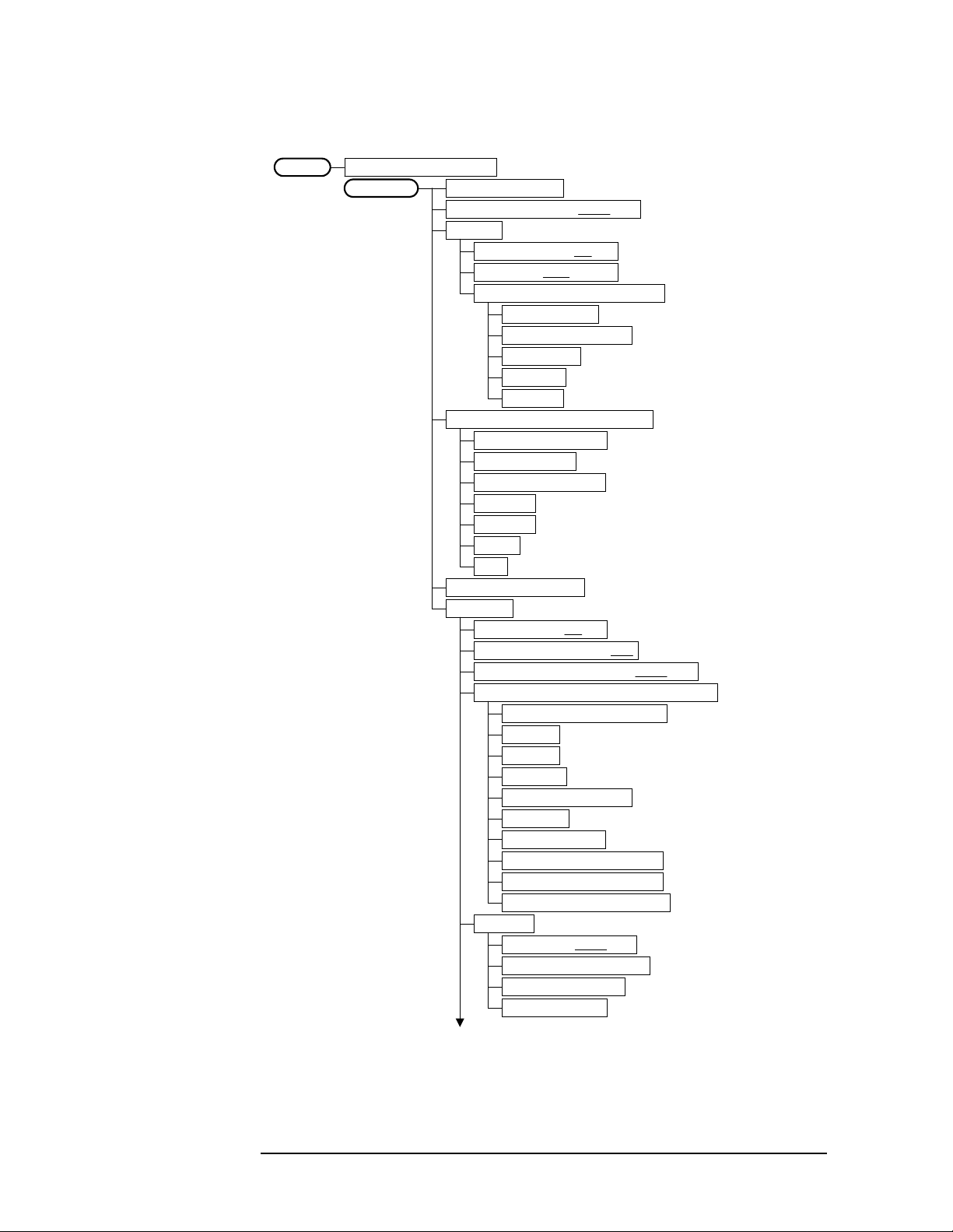
Figure 2-8 QPSK EVM Measurement Key Flow (1 of 2)
Measure
QPSK EVM
Meas Setup
QPSK EVMMeasure
View/Trace
Avg Number 10 On|Off
Avg Mode Exp|Repeat
Meas Interval 256 chips
Trig Source Free Run (Immediate)
Free Run (Immediate)
Video (IF Envlp)
RF Burst (Wideband)
Ext Front
Ext Rear
Frame
Restore Meas Defaults
Advanced
Alpha 0.220
Chip Rate 4.09600 MHz
I/Q Measured Polar Vector
I/Q Measured Polar Constln
I/Q Error (Quad View)
Span X Scale
Scale/Div 25.50 chip
Ref Value 0.000 chip
Ref Position Left|Ctr|Right
Scale CouplingOn|Off
Amplitude Y Scale
Scale/Div 5.00 pcnt
Ref Value 0.00 pcnt
Ref Position Top|Ctr|Bot
Scale CouplingOn|Off
Amplitude Y Scale
Scale/Div 5.00 deg
Ref Value 0.00 deg
Ref Position Top|Ctr |Bot
Scale CouplingOn|Off
Amplitude Y Scale
Scale/Div 5.00 pcnt
Ref Value 0.00 pcnt
Ref Position Top|Ctr |Bot
Scale CouplingOn|Off
<for EVM>
<for Phase Error>
<for Mag Error>
<wcd_evmj.vsd>
26 Chapter2
Setting Up the W-CDMA Mode
W-CDMA Measurement Key Flow
Figure 2-9 QPSK EVM Measurement Key Flow (2 of 2)
QPSK EVMMeasure
I/Q Points 1280 pointsDisplay
Chip Dots On|Off
+45 Degree Rotation On|Off
QPSK EVMMeasure
Marker
Select 1|2|3|4
Normal
Delta
Function Off
Band Power
Noise
Off
Trace EVM
EVM
Phase Error
Mag Error
Off
Shape Diamond
Diamond
Line
Square
Cross
Marker All Off
<not available>
<not available>
<wcd_evm2.vsd>
Chapter 2 27

Setting Up the W-CDMA Mode
W-CDMA Measurement Key Flow
Figure 2-10 Modulation Accuracy Measurement Key Flow (1 of 2)
Measure
Mod Accuracy (Perch Only)
Meas Setup
Mod Accuracy (Perch Only)Measure
View/Trace
Avg Number 10 On|Off
Avg Mode Exp| Repeat
Trig Source Free Run (Immediate)
Free Run (Immediate)
Video (IF Envlp)
RF Burst (Wideband)
Ext Front
Ext Rear
Frame
Scramble Code 1
A
:
F
Done
Spectrum Normal|Invert
Restore Meas Defaults
Advanced
Alpha 0.220
Chip Rate 4.09600 MHz
I/Q Measured Polar Vector
I/Q Measured Polar Constln
I/Q Error (Quad View)
Span X Scale
Amplitude Y Scale
Amplitude Y Scale
Amplitude Y Scale
<for ARIB & Trial 1998 BTS tests>
<to enter a hexadecimal value>
Scale/Div 230.3 chip
Ref Value 0.000 chip
Ref Position Left|Ctr|Right
Scale CouplingOn|Off
Scale/Div 5.00 pcnt
Ref Value 0.00 pcnt
Ref Position Top|Ctr|Bot
Scale CouplingOn|Off
Scale/Div 5.00 deg
Ref Value 0.00 deg
Ref Position Top|Ctr |Bot
Scale CouplingOn|Off
Scale/Div 5.00 pcnt
Ref Value 0.00 pcnt
Ref Position Top|Ctr |Bot
Scale CouplingOn|Off
<for EVM>
<for Phase Error>
<for Mag Error>
<wcd_mdac.vsd>
28 Chapter2
Setting Up the W-CDMA Mode
W-CDMA Measurement Key Flow
Figure 2-11 Modulation Accuracy Measurement Key Flow (2 of 2)
Mod Accuracy (Perch Only)Measure
I/Q Points 512 pointsDisplay
Chip Dots On|Off
+45 Degree Rotation On|Off
Mod Accuracy (Perch Only)Measure
Marker
Select 1|2|3|4
Normal
Delta
Function Off
Band Power
Noise
Off
Trace EVM
EVM
Phase Error
Mag Error
Off
Shape Diamond
Diamond
Line
Square
Cross
Marker All Off
<not available>
<not available>
<wcd_mda2.vsd>
Chapter 2 29
Setting Up the W-CDMA Mode
W-CDMA Measurement Key Flow
Figure 2-12 Spectrum (Freq Domain) Measurement Key Flow (1 of 3)
Measure
Spectrum (Freq Domain)
Meas Setup
Span 1.00000 MHz
Res BW 20.0000 kHz Auto|Man
Average
Trig Source Free Run (Immediate)
Restore Meas Defaults
Advanced
Avg Number 25 On|Off
Avg Mode Exp |Repeat
Avg Type Log-Pwr Avg (Video)
Pwr Avg (RMS)
Log-Pwr Avg (Video)
Voltage Avg
Maximum
Minimum
Free Run (Immediate)
Video (IF Envlp)
RF Burst (Wideband)
Ext Front
Ext Rear
Frame
Line
Pre-ADC BPF On|Off
Pre-FFT Fltr Gaussian|Flat
Pre-FFT BW 1.55000 MHz Auto|Man
FFT Window Flat Top (High Amptd Acc)
Flat Top (High Amptd Acc)
Uniform
Hanning
Hamming
Gaussian (Alpha 3.5)
Blackman
Blackman-Harris
K-B 70 dB (Kaiser-Bessel)
K-B 90 dB (Kaiser-Bessel)
K-B 110 dB (Kaiser-Bessel)
FFT Size
Length CtrlAuto|Man
Min Pnts/RBW 1.300000
Window Length 706
FFT Length 4096
<if Length Ctrl = Auto>
<if Length Ctrl = Man>
<if Length Ctrl = Man>
(a)
<wcd_spct.vsd>
30 Chapter2
 Loading...