

User’s Guide
Part Number: E3640-90001
February 2008.
For Safety information, Warranties, and Regulatory information,
see the pages behind the Index.
© Copyright Agilent Technologies 1999 - 2008
All Rights Reserved.
Agilent Technologies E364xA
Single Output DC Power Supplies

The Agilent Technologies E3640A/E3641A (30 watt), E3642A/E3643A (50 watt),
and E3644A/E3645A (80 watt) are high performance single-output dual range
programmable DC power sup pli es wi th GPIB and RS- 232 interfaces. The
combination of bench-top and system features in these power supplies
provides versatile solutions for your design and test requirements.
Convenient bench-top features
• Single-output dual range
• Output on/off
• High accuracy and high resolution
• Excellent load and line regulation
• Low ripple and noise
• Overvoltage protection
• Five Operating states storage
• Easy-to-use controls
• Remote voltage sensing
• Front and Rear output terminals
• Portable, ruggedized case with non-sk id feet
• Highly visible vacuum-fluorescent displays
• Error messages availabl e on the display
Flexible system features
• GPIB (IEEE-488) and RS-232 interfaces are standard
• SCPI (Standard Commands for Programmable Instruments) compatibility
• I/O setup easily done from front-panel
• Software calibration, no internal physical adjustments
Agilent Technologies E364xA
Single Output DC Power Supplies
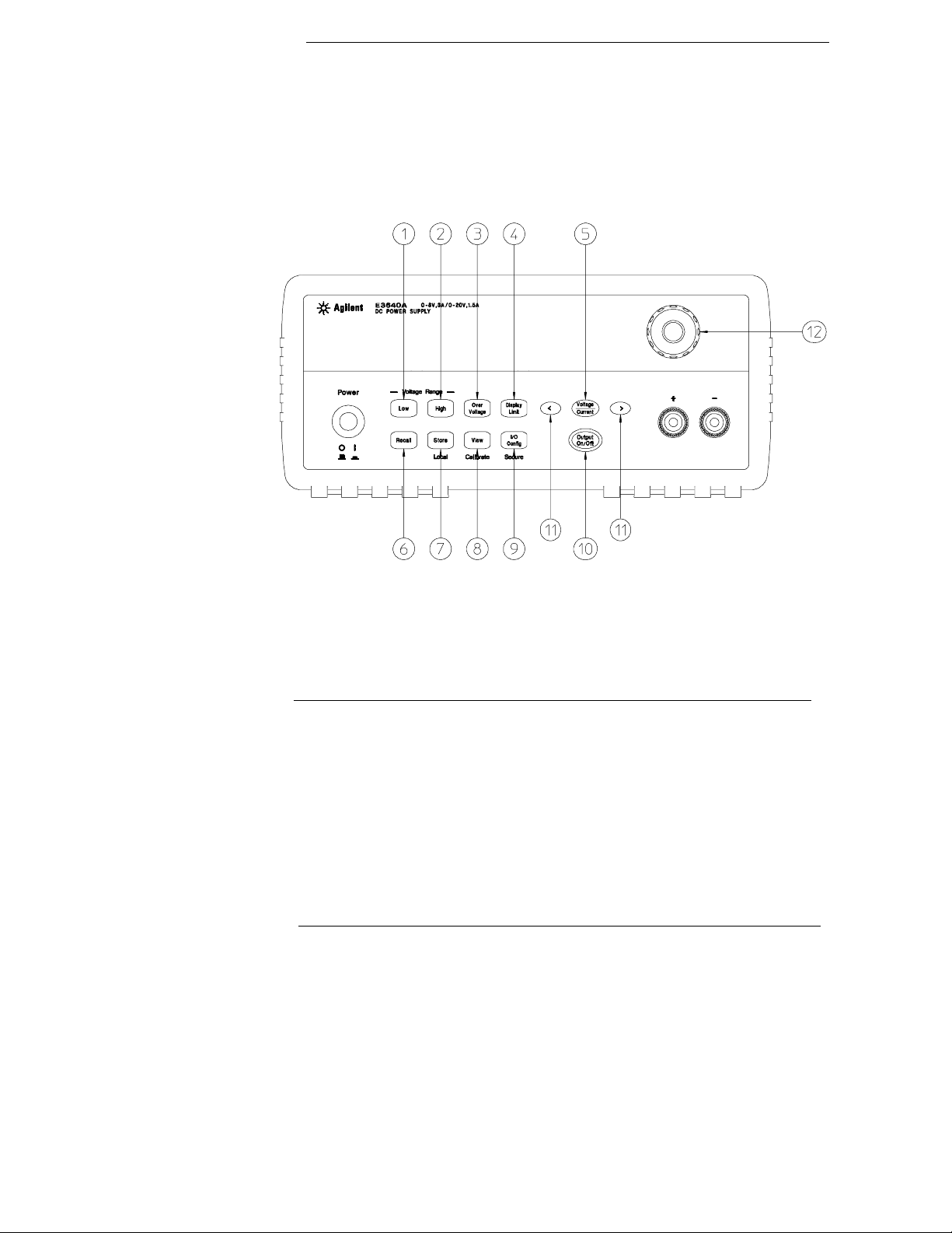
The Front Panel at a Glance
1 Low voltage range selection Key
2 High voltage range selection Key
3 Overvoltage protection Key
4 Display limit Key
5 Voltage/Current adjust selection Key
6 Stored state Recall/Reset Menu
7 State storage menu/Local Key
8 View menu/Calibrate Key
9 I/O Configuration menu/Secure Key
10 Output On/Off Key
11 Resolution selection Keys
12 Knob
2
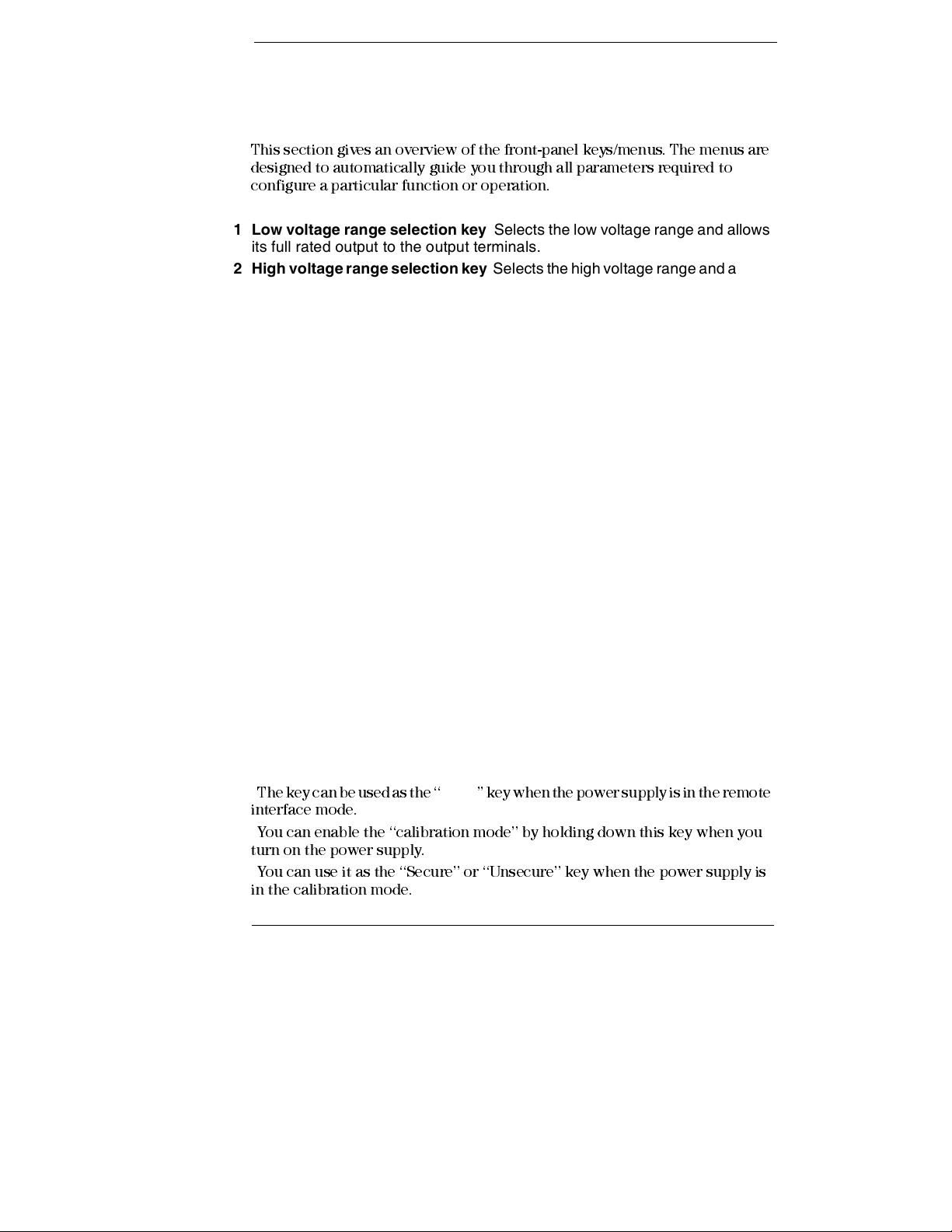
Front-Panel Menu/Key Reference
This section gives an overview of the front-panel keys/menus. The menus are
designed to automatically guide you through all parameters required to
configure a particular function or operation.
1 Low voltage range selection key Selects the low voltage range and allows
its full rated output to the output terminals.
2 High voltage range selection key Selects the high voltage range and allows
its full rated output to the output terminals.
3 Overvoltage protection key Enables or disables the overvoltage protection
function, sets trip voltage level, and clears the overvoltage condition.
4 Display limit key Shows voltage and current limit values on the display and
allows the knob adjustment for setting limit values.
5 Voltage/Current adjust selection key Selects the knob control function for
voltage or current adjustment.
6 Stored state recall menu Recalls a stored operating state from location ‘‘1’’
through ‘‘5’’ and resets the power supply to the power-on state (*RST
command) from the front panel by selecting the ‘‘RESET’’ from this menu.
7 State storage menu / Local key1 Stores up to five power supply’s states in
non-volatile memory and assigns a name to each of the storage locations / or
returns the power supply to local mode from remote interface mode.
8 View menu / Calibrate key2 Views the error codes and the text of the error
message, calibration string, and system firmware revision / or enables
calibration mode.
9 I/O Configuration / Secure key3 Configures the power supply for remote
interfaces / or secures or unsecures the power supply for calibration.
10 Output On/Off key Enables or disables the power supply output. This key
toggles between on and off.
11 Resolution selection keys Move the flashing digit to the right or left and
adjust the scrolling speed of the text being displayed in the View menu.
12 Knob Increases or decreases the value of the flashing digit by turning
clockwise or counter clockwise.
1
The key can be used as the ‘‘
Local
’’ key when the power supply is in the remote
interface mode.
2
You can enable the ‘‘calibration mode’’ by holding down this key when you
turn on the power supply.
3
You can use it as the ‘‘Secure’’ or ‘‘Unsecure’’ key when the power supply is
in the calibration mode.
3
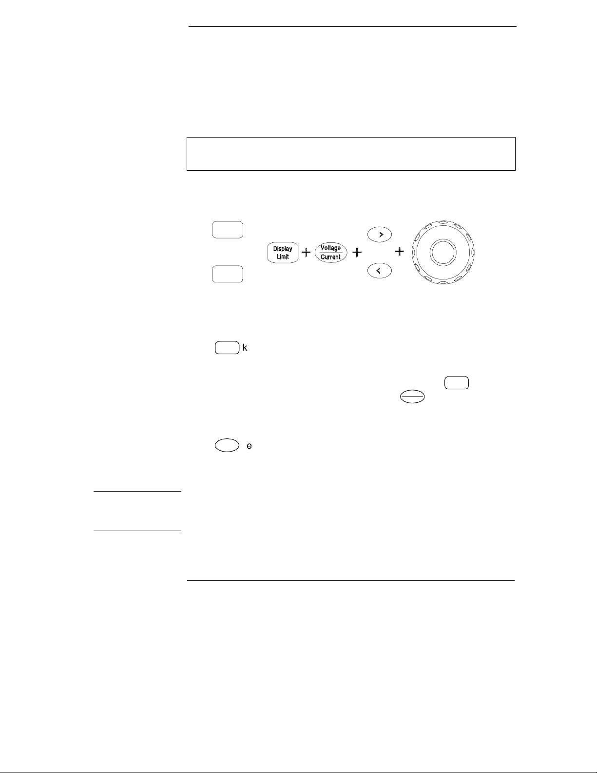
Front-Panel Voltage and Current Limit Settings
You can set the voltage and current limit values from the front panel using the
following method.
Use the voltage/current adjust selection key, the resolution selection keys,
and the control knob to change the voltage and current limit values.
Low
Or
+
High
1 Select the desired voltage range using the voltage range selection keys after
turning on the power supply.
2 Press
3 Move the blinking digit to the appropriate position using the resolution
selection keys and change the blinking digit value to the desired voltage limit
by turning the control knob. If the display limit times out, press
4 Set the knob to current control mode by pressing key.
5 Move the blinking digit to the appropriate position using the resolution
selection keys and change the blinking digit value to the desired current limit
by turning the control knob.
6 Press
go to output monitoring mode automatically to display the voltage and current
at the output.
Display
key to show the limit values on the display.
Limit
Display
Voltag e
Current
Output
key to enable the output. After about 5 seconds, the display will
On/Off
Limit
key again.
Note All front panel keys and controls can be disabled with remote interface commands.
The power supply must be in "
Local" mode for the front panel keys and controls to
function.
4
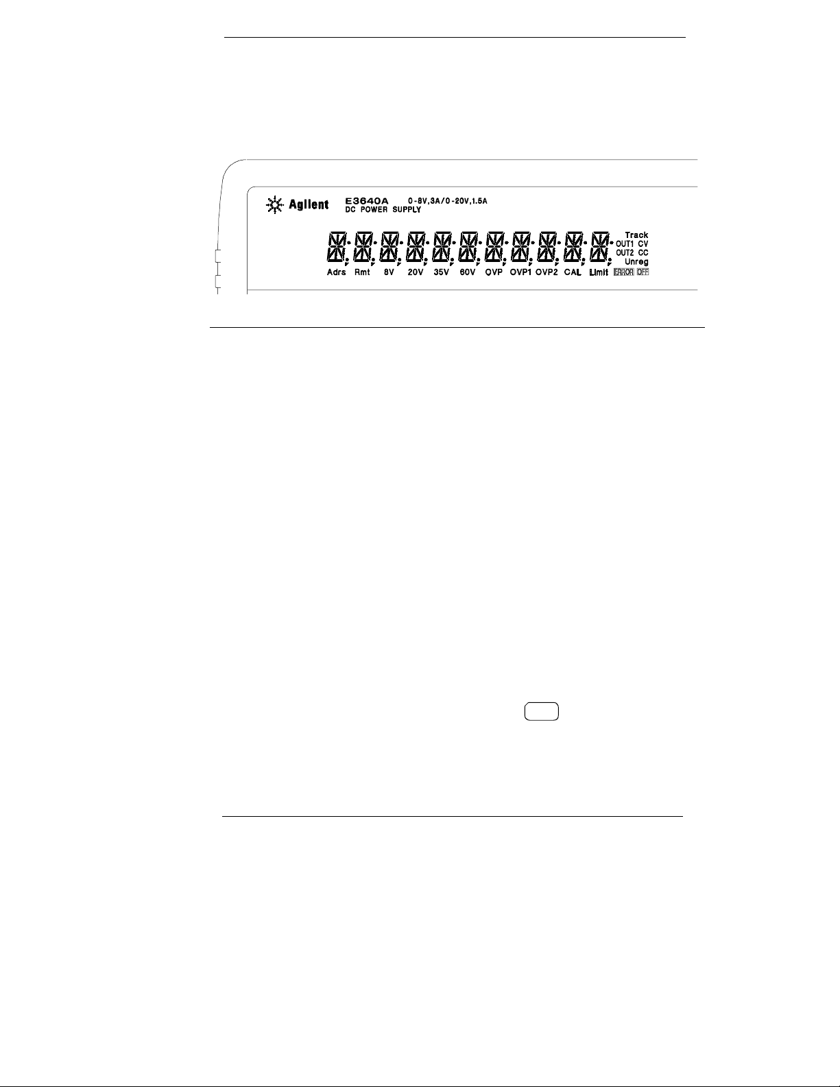
Display Annunciators
Adrs Power supply is addressed to listen or talk over a remote interface.
Rmt Power supply is in remote interface mode.
8V* Shows the low voltage range is selected.
20V* Shows the high voltage range is selected.
35V** Shows the low voltage range is selected.
60V** Shows the high voltage range is selected.
OVP The overvoltage protection function is enabled when the
annunciator turns on or the overvoltage protection circuit has
caused the power supply to shutdown when the annunciator blinks.
CAL The power supply is in calibration mode.
Limit The display shows the limit values of voltage and current.
ERROR Hardware or remote interface command errors are detected and
the error bit has not been cleared.
OFF The output of the power supply is disabled (See page 54 for more
information).
Unreg The output of the power supply is unregulated (output is neither CV
nor CC).
CV The power supply is in constant voltage mode.
CC The power supply is in constant current mode.
To review the display annunciators, hold down key as you turn on
Display
Limit
the power supply.
*For E3640A/42A/44A model. **For E3641A/43A/45A model.
5
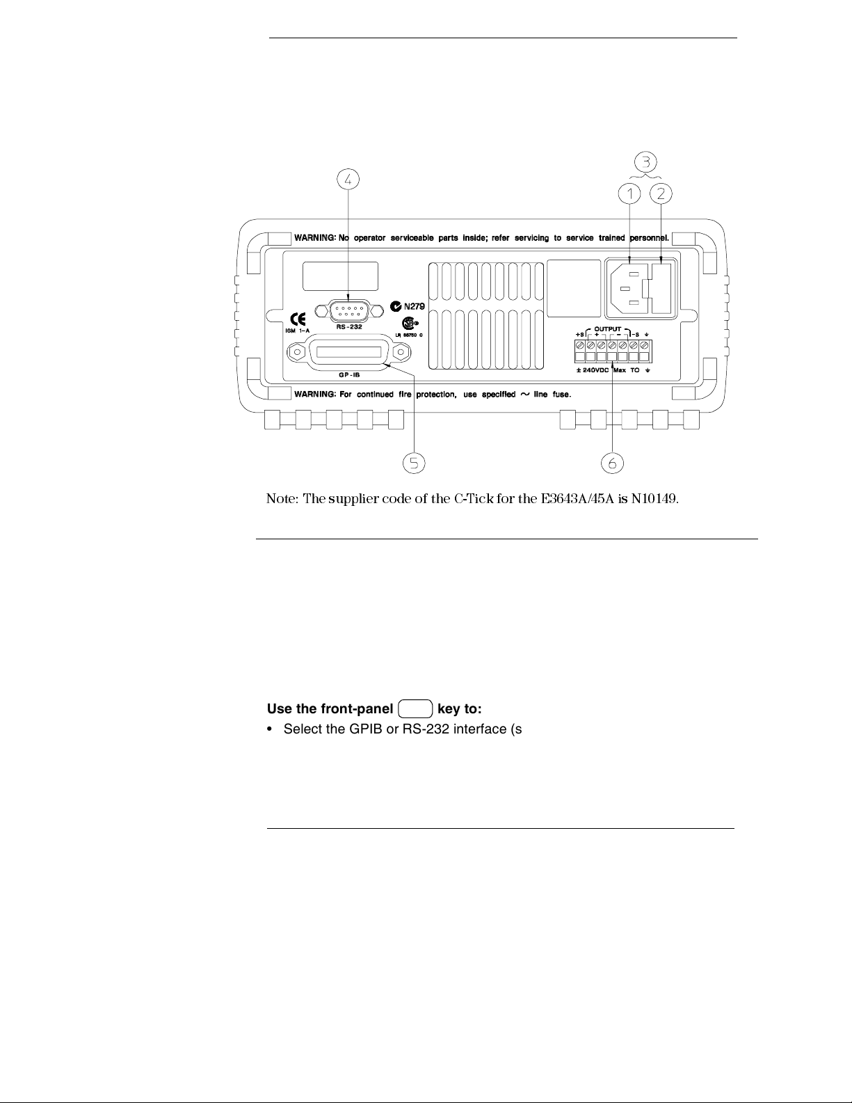
The Rear Panel at a Glance
Note: The supplier code of the C-Tick for the E3643A/45A is N10149.
1 AC inlet
2 Power-line fuse-holder assembly
3 Power-line module
Use the front-panel key to:
I/O
Config
4 RS-232 interface connector
5 GPIB (IEEE-488) interface connector
6 Rear output terminals
• Select the GPIB or RS-232 interface (see chapter 3).
• Set the GPIB address (see chapter 3).
• Set the RS-232 baud rate and parity (see chapter 3).
6
In This Book
Quick Start
the front panel feature.
General Information
power supply. This chapter also provides instructions for installation of your
power supply and the output connections.
Front- Pa ne l O per ati on
keys and how they are used to operate the power supply from the front panel.
This chapter also shows how to configure the power supply for the remote
interface and gives a brief introduction to the calibration features.
Remo te Int e rf a c e R ef e r e nc e
help you program the power supply over the remote interface. This chapter
also explains how to program for status reporting.
Error Messages
are working with the power supply. Each listing contains information to help
you diagnose and solve the problem.
Application Programs
applications to help you develop programs for your application.
Tutorial
gives specific details on the operation and use of your power supply.
Specifications
Chapter 1 helps you get familiar with a few of the power supply’s
Chapter 2 contains a general description of your
Chapter 3 describes in detail the use of front-panel
Chapter 4 contains reference information to
Chapter 5 lists the error messages that may appear as you
Chapter 6 contains some remote interface
Chapter 7 describes basic operation of linear power supplies and
Chapter 8 lists the power supply’s specifications .
Service Information
Agilent Technologies for servicing, procedures for verification & calibration,
and schematics.
If you have questions relating to the operation of the power supply, call
1-800-829-4444 in the United States, or contact your nearest Agilent
Technologies Sales Office.
If your power supply fails within one year of purchase, Agilent will repair
or replace it free of charge. Call 1-800-258-5165 ("Express Exchange") in
the United States, or contact your nearest Agilent Technologies Sales Office.
Contains guid eli nes to return your power supply to
7

8
Contents
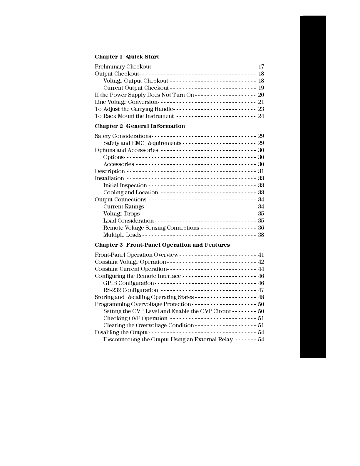
Chapter 1 Quick Start
Preliminary Checkout- - - - - - - - - - - - - - - - - - - - - - - - - - - - - - - - - - 17
Output Checkout- - - - - - - - - - - - - - - - - - - - - - - - - - - - - - - - - - - - - - 18
Voltage Output Checkout - - - - - - - - - - - - - - - - - - - - - - - - - - - - 18
Current Output Checkout - - - - - - - - - - - - - - - - - - - - - - - - - - - - 19
If the Power Supply Does Not Turn On - - - - - - - - - - - - - - - - - - - - 20
Line Voltage Conversion- - - - - - - - - - - - - - - - - - - - - - - - - - - - - - - - 21
To Adjust the Carrying Handle- - - - - - - - - - - - - - - - - - - - - - - - - - - 23
To Rack Mount the Instrument - - - - - - - - - - - - - - - - - - - - - - - - - - 24
Chapter 2 General Information
Safety Considerations- - - - - - - - - - - - - - - - - - - - - - - - - - - - - - - - - - 29
Safety and EMC Requirements - - - - - - - - - - - - - - - - - - - - - - - - 29
Options and Accessories - - - - - - - - - - - - - - - - - - - - - - - - - - - - - - - 30
Options- - - - - - - - - - - - - - - - - - - - - - - - - - - - - - - - - - - - - - - - - - - 30
Accessories - - - - - - - - - - - - - - - - - - - - - - - - - - - - - - - - - - - - - - - 30
Description - - - - - - - - - - - - - - - - - - - - - - - - - - - - - - - - - - - - - - - - - - 31
Installation - - - - - - - - - - - - - - - - - - - - - - - - - - - - - - - - - - - - - - - - - - 33
Initial Inspection - - - - - - - - - - - - - - - - - - - - - - - - - - - - - - - - - - - 33
Cooling and Location - - - - - - - - - - - - - - - - - - - - - - - - - - - - - - - 33
Output Connections - - - - - - - - - - - - - - - - - - - - - - - - - - - - - - - - - - - 34
Current Ratings - - - - - - - - - - - - - - - - - - - - - - - - - - - - - - - - - - - - 34
Voltage Drops - - - - - - - - - - - - - - - - - - - - - - - - - - - - - - - - - - - - - 35
Load Consideration- - - - - - - - - - - - - - - - - - - - - - - - - - - - - - - - - 35
Remote Voltage Sensing Connections - - - - - - - - - - - - - - - - - - 36
Multiple Loads- - - - - - - - - - - - - - - - - - - - - - - - - - - - - - - - - - - - - 38
Contents
Chapter 3 Front-Panel Operation and Features
Front-Panel Operation Overview- - - - - - - - - - - - - - - - - - - - - - - - - 41
Constant Voltage Operation - - - - - - - - - - - - - - - - - - - - - - - - - - - - - 42
Constant Current Operation- - - - - - - - - - - - - - - - - - - - - - - - - - - - - 44
Configuring the Remote Interface - - - - - - - - - - - - - - - - - - - - - - - - 46
GPIB Configuration- - - - - - - - - - - - - - - - - - - - - - - - - - - - - - - - - 46
RS-232 Configuration - - - - - - - - - - - - - - - - - - - - - - - - - - - - - - - 47
Storing and Recalling Operating States - - - - - - - - - - - - - - - - - - - - 48
Programming Overvoltage Protection- - - - - - - - - - - - - - - - - - - - - 50
Setting the OVP Level and Enable the OVP Circuit - - - - - - - - 50
Checking OVP Operation - - - - - - - - - - - - - - - - - - - - - - - - - - - - 51
Clearing the Overvoltage Condition - - - - - - - - - - - - - - - - - - - - 51
Disabling the Output- - - - - - - - - - - - - - - - - - - - - - - - - - - - - - - - - - - 54
Disconnecting the Output Using an External Relay - - - - - - - 54
9

Contents
System-Related Operations- - - - - - - - - - - - - - - - - - - - - - - - - - - - - - 55
State Storage - - - - - - - - - - - - - - - - - - - - - - - - - - - - - - - - - - - - - - 55
Self-Test - - - - - - - - - - - - - - - - - - - - - - - - - - - - - - - - - - - - - - - - - - 56
Error Conditions - - - - - - - - - - - - - - - - - - - - - - - - - - - - - - - - - - - 56
Firmw are Revisi on Query - - - - - - - - - - - - - - - - - - - - - - - - - - - - 57
SCPI Language Version - - - - - - - - - - - - - - - - - - - - - - - - - - - - - - 57
GPIB Interface Reference- - - - - - - - - - - - - - - - - - - - - - - - - - - - - - - 58
RS-232 Interface Reference- - - - - - - - - - - - - - - - - - - - - - - - - - - - - - 59
RS-232 Configurati on Overview - - - - - - - - - - - - - - - - - - - - - - - 59
RS-232 Data Frame Format - - - - - - - - - - - - - - - - - - - - - - - - - - - 59
Connection to a Computer or Termi nal - - - - - - - - - - - - - - - - - 60
RS-232 Troubles hooti ng- - - - - - - - - - - - - - - - - - - - - - - - - - - - - - 61
Calibration Overview - - - - - - - - - - - - - - - - - - - - - - - - - - - - - - - - - - 62
Calibration Security- - - - - - - - - - - - - - - - - - - - - - - - - - - - - - - - - 62
To Unsecure for Calibration - - - - - - - - - - - - - - - - - - - - - - - - - - 63
To Secure Against Calib ration - - - - - - - - - - - - - - - - - - - - - - - - - 64
Calibration Count- - - - - - - - - - - - - - - - - - - - - - - - - - - - - - - - - - - 65
Calibration Message- - - - - - - - - - - - - - - - - - - - - - - - - - - - - - - - - 66
Chapter 4 Remote Interface Reference
SCPI Command Summary- - - - - - - - - - - - - - - - - - - - - - - - - - - - - - - 69
Contents
Simpli fied Pro gramm in g Overview - - - - - - - - - - - - - - - - - - - - - - - - 74
Using the
Using the Low-Level Com mands - - - - - - - - - - - - - - - - - - - - - - - 74
Reading a Query Response - - - - - - - - - - - - - - - - - - - - - - - - - - - 75
Selecting a Trigger Source - - - - - - - - - - - - - - - - - - - - - - - - - - - - 75
Power Supply Programm i ng Ranges- - - - - - - - - - - - - - - - - - - - 76
Using the
Output Setting and Operation Commands - - - - - - - - - - - - - - - - - - 78
Triggering- - - - - - - - - - - - - - - - - - - - - - - - - - - - - - - - - - - - - - - - - - - - 82
Trigger Source Choices - - - - - - - - - - - - - - - - - - - - - - - - - - - - - - 82
Triggering Commands - - - - - - - - - - - - - - - - - - - - - - - - - - - - - - - 84
System-Related Commands - - - - - - - - - - - - - - - - - - - - - - - - - - - - - 85
State Storage Commands - - - - - - - - - - - - - - - - - - - - - - - - - - - - - - - 88
Calibration Commands - - - - - - - - - - - - - - - - - - - - - - - - - - - - - - - - - 89
Interface Configuration Comm ands - - - - - - - - - - - - - - - - - - - - - - - 92
The SCPI Status Registers- - - - - - - - - - - - - - - - - - - - - - - - - - - - - - - 93
What is an
What is an
SCPI Status System - - - - - - - - - - - - - - - - - - - - - - - - - - - - - - - - - 94
The Questionable Status Register - - - - - - - - - - - - - - - - - - - - - - 95
The Standard Event Register- - - - - - - - - - - - - - - - - - - - - - - - - - 96
APPLy
APPLy
Event
Enable
Command - - - - - - - - - - - - - - - - - - - - - - - - - - 74
Command - - - - - - - - - - - - - - - - - - - - - - - - - - - - - 77
Register? - - - - - - - - - - - - - - - - - - - - - - - - - - - 93
Register? - - - - - - - - - - - - - - - - - - - - - - - - - - 93
10
Contents
The Status Byte Register- - - - - - - - - - - - - - - - - - - - - - - - - - - - - 97
Using Service Request (SRQ) and Serial POLL - - - - - - - - - - - 98
Using *STB? to Read the Status Byte- - - - - - - - - - - - - - - - - - - 99
Using the Message Available Bit (MAV)- - - - - - - - - - - - - - - - - 99
To Interrupt Your Bus Controll er Usi ng SRQ - - - - - - - - - - - - 99
To Determine When a Command Sequence is Com pl eted - 100
Using *OPC to Signal When Data is in th e Output Buffer - - 100
Status Reporting Commands - - - - - - - - - - - - - - - - - - - - - - - - - - - 101
An Introduction to the SCPI Language - - - - - - - - - - - - - - - - - - - 103
Command Format Used in This Manual- - - - - - - - - - - - - - - - 104
Command Separators - - - - - - - - - - - - - - - - - - - - - - - - - - - - - - 105
Using the
Querying Parameter Settings - - - - - - - - - - - - - - - - - - - - - - - - 106
SCPI Command Terminators - - - - - - - - - - - - - - - - - - - - - - - - 106
IEEE-488.2 Common Commands - - - - - - - - - - - - - - - - - - - - - 106
SCPI Parameter Types - - - - - - - - - - - - - - - - - - - - - - - - - - - - - 107
Halting an Output in Progress - - - - - - - - - - - - - - - - - - - - - - - - - - 108
SCPI Conformance Information- - - - - - - - - - - - - - - - - - - - - - - - - 109
IEEE-488 Conformance Information - - - - - - - - - - - - - - - - - - - - - 112
Chapter 5 Error Messages
MIN
and
MAX
Parameters - - - - - - - - - - - - - - - - - - 105
Contents
Execution Errors - - - - - - - - - - - - - - - - - - - - - - - - - - - - - - - - - - - - 115
Self-Test Errors- - - - - - - - - - - - - - - - - - - - - - - - - - - - - - - - - - - - - - 120
Calibration Errors- - - - - - - - - - - - - - - - - - - - - - - - - - - - - - - - - - - - 121
Chapter 6 Application Programs
Example Program for C and C++- - - - - - - - - - - - - - - - - - - - - - - - 125
Example Program for Excel 97 - - - - - - - - - - - - - - - - - - - - - - - - - 129
Chapter 7 Tutorial
Overview of this Power Supply Operation - - - - - - - - - - - - - - - - 137
Output Characteristics - - - - - - - - - - - - - - - - - - - - - - - - - - - - - - - - 139
Unregulated State - - - - - - - - - - - - - - - - - - - - - - - - - - - - - - - - - 141
Unwanted Signals - - - - - - - - - - - - - - - - - - - - - - - - - - - - - - - - - 141
Extending the Voltage and Current Range - - - - - - - - - - - - - - - - 143
Series Connections - - - - - - - - - - - - - - - - - - - - - - - - - - - - - - - - 143
Parallel Connections- - - - - - - - - - - - - - - - - - - - - - - - - - - - - - - 143
Remote Programming- - - - - - - - - - - - - - - - - - - - - - - - - - - - - - - - - 144
Chapter 8 Specifications
Performance Specifications - - - - - - - - - - - - - - - - - - - - - - - - - - - - 149
Supplemental Characteristics - - - - - - - - - - - - - - - - - - - - - - - - - - 151
11
Contents
Appendix Service Information
Operating Checklist- - - - - - - - - - - - - - - - - - - - - - - - - - - - - - - - - - - 157
Is the Power Supply Inoperative? - - - - - - - - - - - - - - - - - - - - - 157
Does the Power Supply Fail Self-T est? - - - - - - - - - - - - - - - - - 157
Types of Service Available - - - - - - - - - - - - - - - - - - - - - - - - - - - - - 158
Standard Repair Service (worldwi de)- - - - - - - - - - - - - - - - - - 158
Express Ex change (U.S.A . only) - - - - - - - - - - - - - - - - - - - - - - 158
Repacking for Shipment - - - - - - - - - - - - - - - - - - - - - - - - - - - - - - - 159
Electrostatic Discharge (ES D) Precautions - - - - - - - - - - - - - - - - 160
Surface Mount Repair - - - - - - - - - - - - - - - - - - - - - - - - - - - - - - - - - 160
To Replace the Power-Line Fuse - - - - - - - - - - - - - - - - - - - - - - - - 160
Troubleshooting Hints- - - - - - - - - - - - - - - - - - - - - - - - - - - - - - - - - 161
Unit Reports Error s 740 to 750 - - - - - - - - - - - - - - - - - - - - - - - 161
Unit Fails Self-Test- - - - - - - - - - - - - - - - - - - - - - - - - - - - - - - - - 161
Bias Supplies Problems- - - - - - - - - - - - - - - - - - - - - - - - - - - - - 161
Self-Test Procedures- - - - - - - - - - - - - - - - - - - - - - - - - - - - - - - - - - 162
Power-On Self-Test - - - - - - - - - - - - - - - - - - - - - - - - - - - - - - - - 162
Complete Self-Test- - - - - - - - - - - - - - - - - - - - - - - - - - - - - - - - - 162
General Disassembly- - - - - - - - - - - - - - - - - - - - - - - - - - - - - - - - - - 164
Recommended Test Equi pm ent - - - - - - - - - - - - - - - - - - - - - - - - - 165
Test Considerations- - - - - - - - - - - - - - - - - - - - - - - - - - - - - - - - - - - 166
Contents
Operation Verification and Perform ance Tests - - - - - - - - - - - - - 166
Measurement Techniques - - - - - - - - - - - - - - - - - - - - - - - - - - - - - - 167
Setup for Most Tests - - - - - - - - - - - - - - - - - - - - - - - - - - - - - - - 167
Current-M oni toring R esis tor - - - - - - - - - - - - - - - - - - - - - - - - - 167
General Measurement Techniques - - - - - - - - - - - - - - - - - - - - 168
Electronic Load - - - - - - - - - - - - - - - - - - - - - - - - - - - - - - - - - - - 168
Programming - - - - - - - - - - - - - - - - - - - - - - - - - - - - - - - - - - - - - 168
Constant Voltage (CV) Veri ficatio ns- - - - - - - - - - - - - - - - - - - - - - 169
Constant Voltage Test Setup - - - - - - - - - - - - - - - - - - - - - - - - - 169
Voltage Programmi ng and Readback Accuracy - - - - - - - - - - 169
CV Load Effect (Load Regulation) - - - - - - - - - - - - - - - - - - - - 170
CV Source effect (Line Regulation)- - - - - - - - - - - - - - - - - - - - 171
CV PAR D (Ri ppl e and Noise) - - - - - - - - - - - - - - - - - - - - - - - - 171
Load Transient Respons e Tim e - - - - - - - - - - - - - - - - - - - - - - - 173
Constant Current (CC ) Veri ficatio ns - - - - - - - - - - - - - - - - - - - - - 174
Constant Current Test Setup - - - - - - - - - - - - - - - - - - - - - - - - - 174
Current Programm in g and Readback Accuracy- - - - - - - - - - 174
CC Load Effect (Load Regulation) - - - - - - - - - - - - - - - - - - - - 175
CC Source Effect (Line Regulation) - - - - - - - - - - - - - - - - - - - 176
CC PAR D (R ipp le and Noise) - - - - - - - - - - - - - - - - - - - - - - - - 177
Common Mode Current Noise - - - - - - - - - - - - - - - - - - - - - - - - - - 178
12
Contents
Performance Test Record for Your Power Supply - - - - - - - - - - 179
CV Performance Test Record - - - - - - - - - - - - - - - - - - - - - - - - 179
CC Performance Test Record- - - - - - - - - - - - - - - - - - - - - - - - 180
Calibration Reference- - - - - - - - - - - - - - - - - - - - - - - - - - - - - - - - - 181
Agilent Technologies Calibration Services- - - - - - - - - - - - - - 181
Calibration Interval - - - - - - - - - - - - - - - - - - - - - - - - - - - - - - - - 181
To Unsecure the Power Supply Without the Security Code 181
General Calibration/Adjustment Procedure - - - - - - - - - - - - - - - 182
Front Panel Voltage and Current Calibration- - - - - - - - - - - - 183
Calibration Record for Your Power Supply- - - - - - - - - - - - - - - - 187
Calibration Error Messages - - - - - - - - - - - - - - - - - - - - - - - - - - - - 188
Schematics - - - - - - - - - - - - - - - - - - - - - - - - - - - - - - - - - - - - - - - - - 188
Component Locator
Component Locator (
Component Locator for front panel - - - - - - - - - - - - - - - - - - - 191
Index - - - - - - - - - - - - - - - - - - - - - - - - - - - - - - - - - - - - - - - - - - - - - - 192
(top)
for main board assembly - - - - - - 189
bottom)
for main board assembly - - - 190
Contents
13

Contents
Contents
14

1
Quick Start
Quick Start
One of the first things you will want to do with your power supply is to become
acquainted with the front panel. The exercises in this chapter prepare the
power supply for use and help you get familiar with some of its front-panel
operations.
This chapter is intended for both the experienced and the inexperienced user
because it calls attention to certain checks that should be made prior to
operation.
Throughout this chapter the key to be pressed is shown in the left margin.
16
Chapter 1 Quick Start
Preliminary Checkout
Preliminary Checkout
The following steps help you verify that the power supply is ready for use.
1 Check the list of supplied items.
Verify that you have received the following item s with your power sup ply. If
anything is missing, contact your nearest Agilent Technologies Sales Office.
One power cord for your location.
This User’s
Quick Reference Guide.
Certificate of Calibration.
2 Connect the power cord and turn on the power supply.
The front-panel display will light up briefly while the power supply performs
its
power-on self-test
on display with all annunciators turned on, hold down
the power supply. If the power supply does not turn on properly, see page 20.
Guide.
. The GPIB address is also displayed. To review the power-
Display
as you turn on
Limit
1
3 Perform a
The
complete
performed at power-on. Hold down
hold down the key
complete
self-test performs a more extensive set of tests than those
self-test.
Display
as you turn on the power supply and
Limit
until you hear a lon g beep
. The
self-test
will begin when
you release the key following the beep.
If the self- tes t f ails, see t he S ervi ce I nfo rmati on f or inst ructi ons on r eturn ing
the power suppl y to Agilen t Technologies for ser vice .
Note The power supply is shipped from the factory with a power-line cord that has a plug
appropriate for your location. Your power supply is equipped with a 3-wire grounding
type power cord; the third conductor being the ground. The power supply is grounded
only when the power-line cord is plugged into an appropriate receptacle. Do not
operate your power supply without adequate cabinet ground connection.
17

Power
Output
On/Off
Chapter 1 Quick Start
Output Checkout
Output Checkout
The following procedures check to ensure that the power supply develops its
rated outputs and properly responds to operation from the front panel. For
complete performance and verification tests, refer to the
Note:
If an error has been detected during the output checkout procedures,
the
ERROR
annunciator will turn on. See "Error Messages" starting on page
113 in chapter 5 for more information.
Voltage Output Checkout
The following steps verify basic voltage functions with no load.
1 Turn on the power supply.
The power supply will go into the
(the
OFF
annunciator turns on); its low voltage range is selected, and the
annunciator and low voltage range indication annunciator turn on (for
8V
example,
annunciator turns on for the E3640A model); and the knob is
selected for voltage control.
2 Enable the outputs.
power-on / reset
Serv ice I nfo rmati on
state; the output is disabled
OVP
.
The
OFF
annunciator turns off and the CV annunciator turns on. Notice that
the display is in the
meter
mode. ‘‘Meter mode’’ means that the display shows
the actual output voltage and current.
3 Check that the front-panel voltmeter properly responds to knob
control for both low and high voltage range.
Turn the knob clockwise or counter clockwise to check that the voltmeter
responds to knob control and the ammeter indicates nearly zero. The
flashing
digit can be adjusted by turning the knob.
1
4 Ensure that the voltage can be adjusted from zero to the full rated
value by adjusting the knob.
1
You can use the resolution selection keys to move the flashing digit to the
right or left when settin g the voltage.
18
Power
Chapter 1 Quick Start
Output Checkout
Current Output Checkout
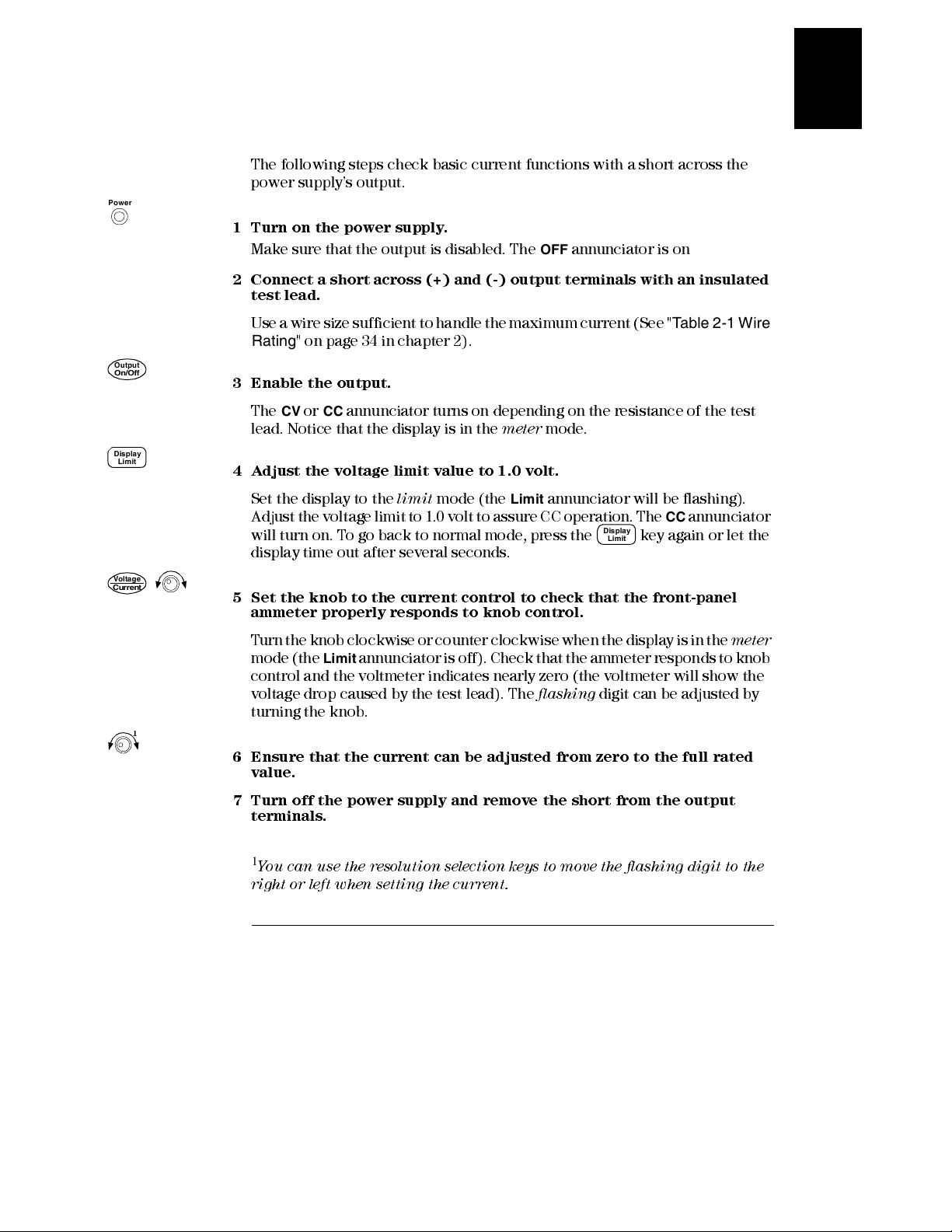
The following steps check basic current functions with a short across the
power supply’s output.
1 Turn on the power supply.
Make sure that the output is disabled. The
2 Conn e c t a s hor t a c r os s (+) a n d (-) o utp ut te r mi n a l s with a n i nsula ted
test lead.
OFF
annunciator is on
1
Output
On/Off
Display
Limit
Voltag e
Current
Use a wire size sufficient to handle the maximum current (See "
Rating
" on page 34 in chapter 2).
Table 2-1 Wire
3 Enable the output.
The CV or CC annunciator turns on depending on the resistance of the test
lead. Notice that the display is in the
meter
mode.
4 Adjust the voltage limit value to 1.0 volt.
Set the display to the
Adjust the voltage limit to 1.0 volt to assure CC operation. The
will turn on. To go back to normal mode, press the
limit
mode (the
Limit
annunciator will be flashi ng).
Display
Limit
CC
key again or let the
annunciator
display time out after several seconds.
5 Set the knob to the current control to check that the front-panel
ammeter properly responds to knob control.
T urn the knob clockwise or counter clockwise when the display is in the
mode (the
Limit
annunciator is off). Check that the ammeter responds to knob
meter
control and the voltmeter indicates nearly zero (the voltmeter will show the
voltage drop caused by the test lead). The
flashing
digit can be adjusted by
turning the knob.
1
6 Ensure that the current can be adjusted from zero to the full rated
value.
7 Turn off the power supply and remove the short from the output
terminals.
1
You can use the resolution selection keys to move the flashing digit to the
right or left when settin g the cur ren t.
19
Chapter 1 Quick Start
If the Power Supply Does Not Turn On
If the Power Supply Does Not Turn On
Use the following steps to help solve problems you might encounter when
turning on the instrument. If you need more help, refer to chapter 5 for
instructions on returnin g the instrument to Agil ent Technologies for service.
1 Verify that there is ac power to the power supply.
First, verify that the power cord is firmly plugged into the power receptacle on
the rear panel of the power supply. Y ou should also make sure that the power
source you plugged the power supply into is energized. Then, verify that the
power supply is turned on.
2 Verify the power-line voltage setting.
The line voltage is set to the proper value for your country when the power
supply is shipped from the factory . Change the voltage setting if it’s not correct.
The settings are: 100, 115, or 230 Vac.
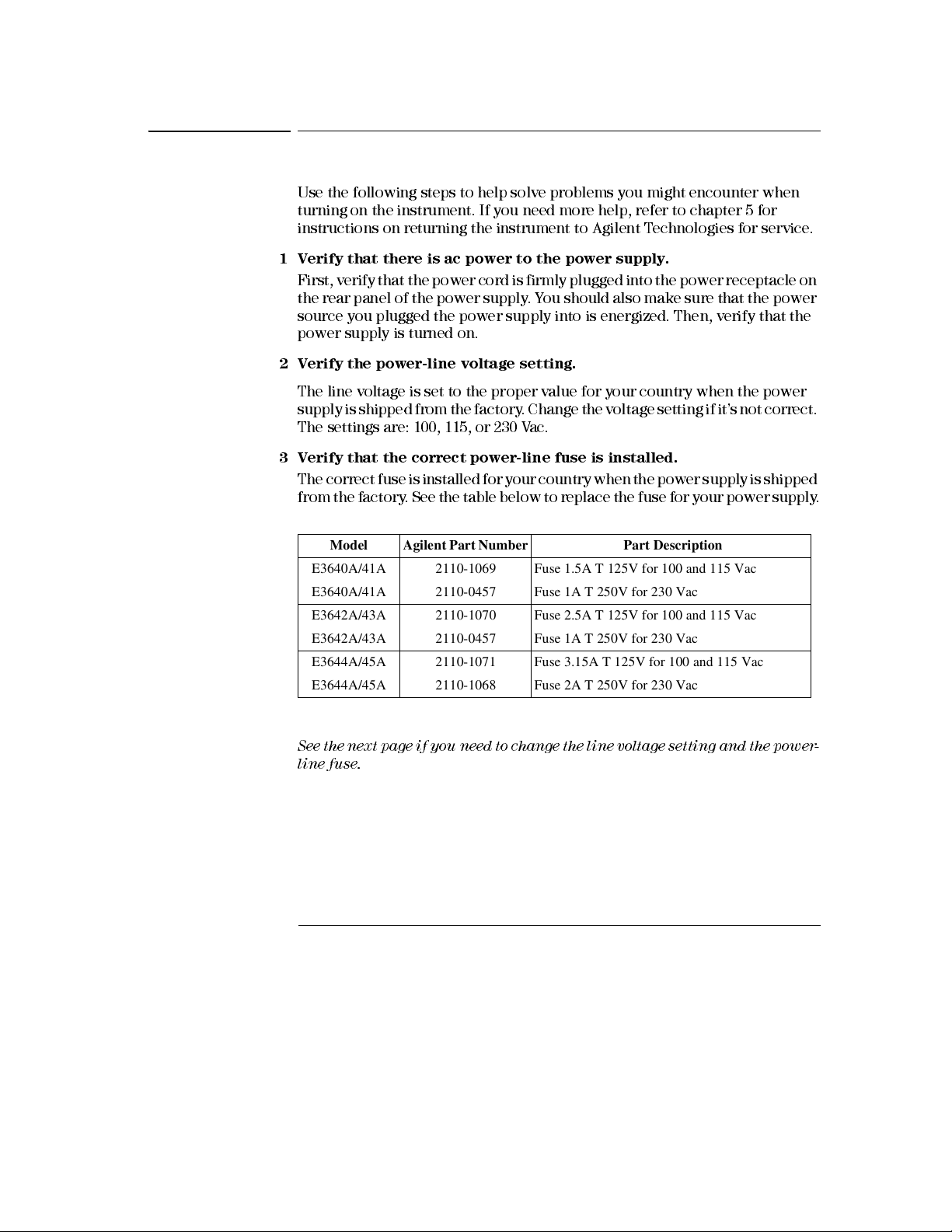
3 Verify that the correct power-line fuse is installed.
The correct fuse is installed for your country when the power supply is shipped
from the factory . See the table below to replace the fuse for your power supply .
Model Agilent Part Number Part Description
E3640A/41A 2110-1069 Fuse 1.5A T 125V for 100 and 115 Vac
E3640A/41A 2110-0457 Fuse 1A T 250V for 230 Vac
E3642A/43A 2110-1070 Fuse 2.5A T 125V for 100 and 115 Vac
E3642A/43A 2110-0457 Fuse 1A T 250V for 230 Vac
E3644A/45A 2110-1071 Fuse 3.15A T 125V for 100 and 115 Vac
E3644A/45A 2110-1068 Fuse 2A T 250V for 230 Vac
See the next page if you need to change the line voltage setting and the power-
line fuse.
20

Chapter 1 Quick Start
Line Voltage Conversion
Line Voltage Conversion
1
Warning
Shock Hazard
Component replacement and internal adjustments must be made only by
qualified service personnel.
Line voltage conversion is accomplished by adjusting two components: the line
voltage selection switch and the power-line fuse on the rear panel.
1
Remove AC line power.
2
Remove the cover (Refer to General Disassembly on page 164).
3
Set two sections of the line voltage selector switch on the PC board for the
desired line voltage (See Figure 1-1 below).
4
See the next page to check the rating of the power-line fuse and replace with
the correct one if necessary.
5
Replace the cover and mark the power supply clearly with a tag or label
indicating the correct line voltage and fuse that is in use.
Operating personnel must not remove power supply covers.
(TOP VIEW)
Figure 1-1. Line Voltage Selector (set for 115Vac)
100V
115 V
230V
21

Chapter 1 Quick Start
Line Voltage Conversion
1 Remove the power cord. Remove
the fuse-holder assembly with a flatblade screwdriver from the rear panel.
3 Replace with the correct fuse.
2 Remove the fuse-holder from the
assembly.
4 Replace the fuse-holder assembly in
rear panel.
Verify that the correct line voltage is selected and the power-line fuse is good.
22
Chapter 1 Quick Start
To Adjust the Carrying Handle
To Adjust the Carrying Handle
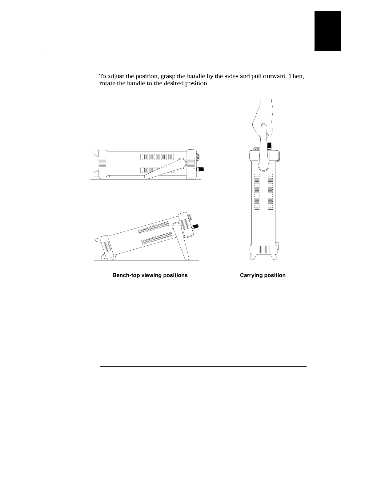
To adjust the position, grasp the handle by the sides and pull outward. Then,
rotate the handle to the desired position.
1
Bench-top viewing positions Carrying position
23

Chapter 1 Quick Start
To Rack Mount the Instrument
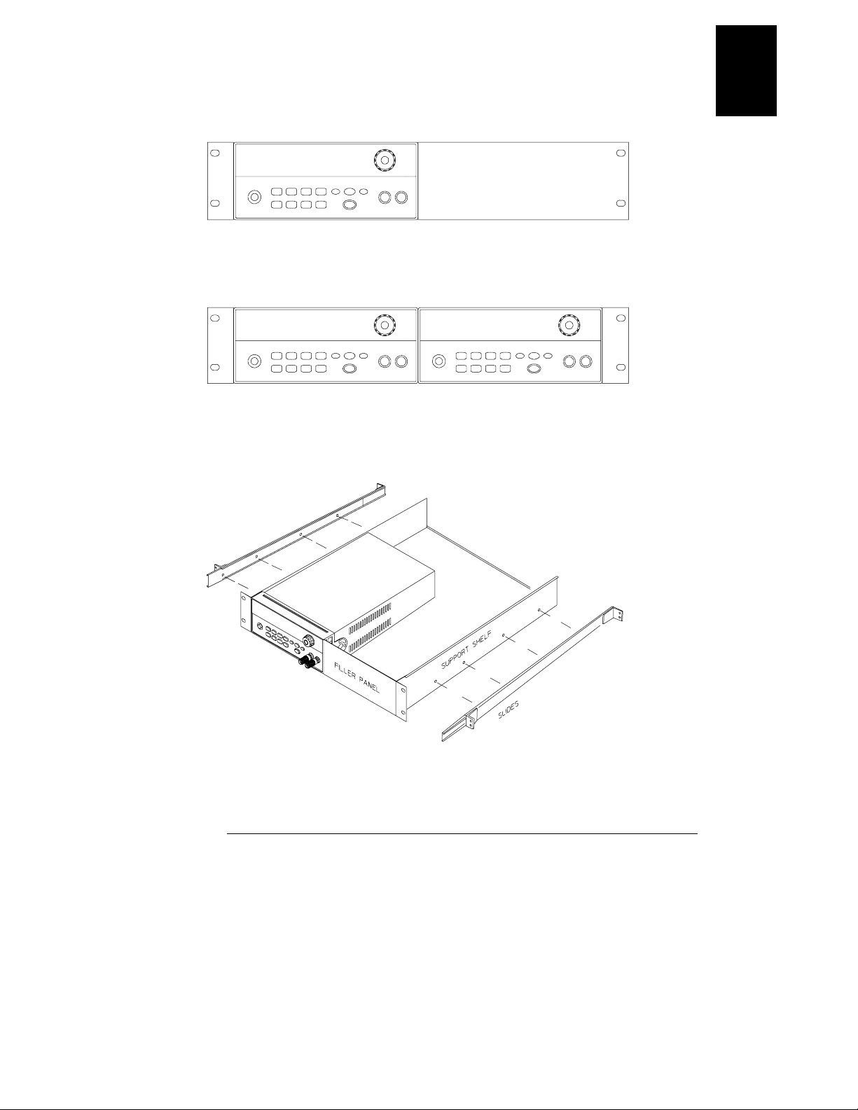
To Rack Mount the Instrument
Y ou can mount the power supply in a standard 19-inch rack cabinet using one
of three optional kits available. Instructions and mounting hardware are
included with each rack-mounting kit. Any Agilent Technologies System II
instrument of the same size can be rack-mounted beside the Agilent E3640A,
E3641A, E3642A, E3643A, E3644A, or E3645A.
Note: Remove the carrying handle, and the front and rear rubber bumpers,
before rack-moun ting the in stru m en t.
To remove the handle, rotate it to the vertical position and pull the ends outward.
Front Rear (bottom view)
To remove the rubber bumper, stretch a corner and then slide it off.
24
Chapter 1 Quick Start
To Rack Mount the Instrument
To rack mount a single instrument, order adapter kit 5063-9240.
To rack mount two instruments side-by-side, order lock-link kit 5061-9694 and
flange kit 5063-9212. Be sure to use the support rails inside the rack cabinet.
1
To install two instruments in a sliding support shelf, order support shelf 5063-9255,
and slide kit 1494-0015.
25

Chapter 1 Quick Start
To Rack Mount the Instrument
26

2
General Information

General Information
This manual descri bes the operation of the Agilent Technologies Model
E3640A, E3641A, E3642A, E3643A, E3644A and E3645A DC power supplies.
This chapter contains a general description of your power supply. This chapter
also provides instructions for installation of your power supply and the output
connections. Unless otherwi se stated, the informati on in this manual appli es
to all the six models. This chapter is divided into the following sections:
• Safety Considerations‚ on page 29
• Options and Accessories‚ on page 30
• Description‚ starting on page 31
• Installation‚ on page 33
• Output Connections‚ on page 34
28
Chapter 2 General Information
Safety Considerations
Safety Considerations
This power supply is a Safety Class I instrument, which means that it has a
protective earth terminal. That terminal must be connected to earth ground
through a power source with a 3-wire ground receptacle.
Before installation or operation , check the power supply and review this
manual for safety markings and instructions. Safety information for specific
procedures is located at the appropriate places in this manual. See also
‘‘
Safety
’’ at the beginning of this manual for general safety information.
Safety and EMC Requirements
This power supply is designed to comply with the following safety and EMC
(Electromagnetic Compatibility) requirements:
• IEC 1010-1(1990)/EN 61010-1(1993) + A2 (1995): Safety Requirements for
Electrical Equipment for Measurement, Control, and Laboratory Use
• CSA C22.2 No.1010.1-92: Safety Requirements for Electrical Equipment for
Measurement, Control, and Laboratory Use
• EN61326-1(1997):
EN 61000-4-2(1995): Electrostatic Discharge Requirements
EN 61000-4-3(1996): Radiated Electromagnetic Fi eld Requi rements
EN 61000-4-4(1995): Electrical Fast Transient/Burst Requirements
EN61000-4-5(1995): Surge Requirements
EN61000-4-6(1996): Conducted Radio Frequency Immunity Requirements
EN61000-4-8(1993): Magnetic Field Requirements
EN61000-4-11(1994): Voltage dips, short, interruption and var Requirement
EN 55011(1991) Group 1, Class A/CISPR 11(1990): Limits and Methods of
Radio Interference Characteristics of Industrial, Scientific, and Medical
(ISM) Radio - Frequency Equipment
• Low Voltage Directive 73/23/EEC
• EMC Directive 89/336/EEC
• ICES/NMB-001
This ISM device complies with Canadian ICES-001.
Cet appareil ISM est conforme à la norme NMB-001 du Canada.
2
29
 Loading...