


ü
+3#(694[$#93:#%(1&+#6(5,(6#' :(5#6833/,(6
23(5$7,1*#0$18$/#)25#02'(/6=
+3#(6947$/#6HULDOV#.5;6836368#DQG#DERYH
+3#(6948$/#6HULDOV#.5;68394<:#DQG#DERYH
+3#(6949$/#6HULDOV#.5;6835984#DQG#DERYH
+3#(694:$/#6HULDOV#.5;6835855#DQG#DERYH
0DQXDO#3DUW#1R1#8<8<08643
)RU#LQVWUXPHQWV#ZLWK#KLJKHU#6HULDO#1XPEHUV#WKDQ#DERYH/
D#FKDQJH#SDJH#PD\#EH#LQFOXGHG1
$XJXVW#4<<<
(GLWLRQ#:
SAFETY SUMMARY
y
y
y
y
y
g
y
g
y
y
y
g
g
y
g
g
y
g
g
y
g
g
y
y
y
g
g
y
y
y
y
g
g
y
g
y
y
g
g
g
y
y
y
The following general safety precautions must be observed during all phases of operation, service, and repair of this instrument.
Failure to compl
manufacture, and intended use of the instrument. Hewlett-Packard Compan
with these requirements.
compl
BEFORE APPLYING POWER.
Verif
that the product is set to match the available line voltage
and that the correct fuse is installed.
GROUND THE INSTRUMENT.
This product is a Safet
tective earth terminal). To minimize shock hazard, the instrument
chassis and cabinet must be connected to an electrical
The instrument must be connected to the ac power suppl
throu
h a three-conductor power cable, with the third wire firml
connected to an electrical ground(safety ground) at the power
outlet. An
disconnection of the protective earth terminal will cause a potential shock hazard that could result in personal injur
ment is to be ener
volta
e reduction, be certain that the autotransformer common
terminal is connected to the neutral(earthed pole) of the ac power
lines (suppl
DO NOT OPERATE IN AN EXPLOSIVE ATMOSPHERE.
Do not operate the instrument in the presence of flammable
ases or fumes.
KEEP AWAY FROM LIVE CIRCUITS.
Operatin
nent replacement and internal adjustments must be made b
qualified service personnel. Do not replace components with
power cable connected. Under certain conditions, dan
a
es may exist even with the power cable removed. To avoid injuries, alwa
external volta
DO NOT SERVICE OR ADJUST ALONE.
Do not attempt internal service or adjustment unless another person, capable of renderin
with these precautions or with specific warnings elsewhere in this manual violates safety standards of design,
assumes no liability for the customer's failure to
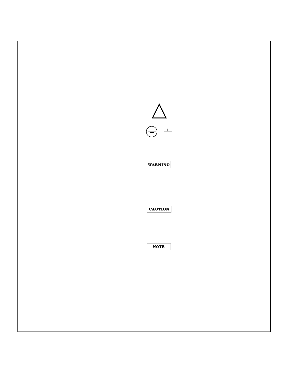
SAFETY SYMBOLS
Instruction manual s
be marked with this s
sar
for the user to refer to the instruction
manual.
Indicate earth(
The WARNING si
calls attention to a procedure, practice,
or the like, which, if not correctl
adhered to, could result inpersonal injur
not proceed be
the indicated conditions are full
and met.
The CAUTION si
attention to an operatin
like, which, if not correctl
adhered to, could result in dama
destruction of part or all of the product. Do
not proceed be
indicated conditions are full
met.
The NOTE si
mation. It calls attention to a procedure, practice, condition or the like, which is essential to
hlight.
hi
er of introducing additional hazards, do not
round) terminal.
Class I instrument (provided with a pro-
round.
mains
interruption of the protective(grounding) conductor or
. If the instru-
ized via an external autotransformer for
mains).
personnel must not remove instrument covers. Compo-
erous volt-
s disconnect power, discharge circuits and remove
e sources before touching components.
first aid and resuscitation, is present.
!
or
DO NOT SUBSTITUTE PARTS OR MODIFY INSTRUMENT.
Because of the dan
install substitute parts or perform an
to the instrument. Return the instrument to a Hewlett-Packard
Sales and Service Office for service and repair to ensure that
safet
features are maintained.
mbol; the product will
mbol when it is neces-
n denotes a hazard. It
performed or
ond a WARNING sign until
n denotes a hazard. It calls
procedure, or the
performed or
ond CAUTION sign until the
understood and
n denotes important infor-
unauthorized modification
. Do
understood
e to or
Instruments that appear damaged or defective should be made inoperative and secured against unintended
operation until the
can be repaired by qualified service personnel.
1-2

Table of Contents
g
g
g
g
g
g
g
g
SAFETY SUMMARY . . . . . . . . . . . . . . . . . . . . . . . . . . . . . . . . . . . . . . . . . . . . . . . . . . . . . . . . . . . . . .1-2
GENERAL INFORMATION. . . . . . . . . . . . . . . . . . . . . . . . . . . . . . . . . . . . . . . . . . . . . . . . . . . . . . . . .1-4
INTRODUCTION . . . . . . . . . . . . . . . . . . . . . . . . . . . . . . . . . . . . . . . . . . . . . . . . . . . . . . . . . . . . . . . . 1-4
SAFETY REQUIREMENTS. . . . . . . . . . . . . . . . . . . . . . . . . . . . . . . . . . . . . . . . . . . . . . . . . . . . . . . .1-4
INSTRUMENT AND MANUAL IDENTIFICATION. . . . . . . . . . . . . . . . . . . . . . . . . . . . . . . . . . . . . . .1-4
OPTIONS. . . . . . . . . . . . . . . . . . . . . . . . . . . . . . . . . . . . . . . . . . . . . . . . . . . . . . . . . . . . . . . . . . . . . .1-4
ACCESSORY . . . . . . . . . . . . . . . . . . . . . . . . . . . . . . . . . . . . . . . . . . . . . . . . . . . . . . . . . . . . . . . . . .1-4
DESCRIPTION . . . . . . . . . . . . . . . . . . . . . . . . . . . . . . . . . . . . . . . . . . . . . . . . . . . . . . . . . . . . . . . . . 1-4
SPECIFICATIONS. . . . . . . . . . . . . . . . . . . . . . . . . . . . . . . . . . . . . . . . . . . . . . . . . . . . . . . . . . . . . . .1-5
INSTALLATION. . . . . . . . . . . . . . . . . . . . . . . . . . . . . . . . . . . . . . . . . . . . . . . . . . . . . . . . . . . . . . . . . .1-6
INITIAL INSPECTION . . . . . . . . . . . . . . . . . . . . . . . . . . . . . . . . . . . . . . . . . . . . . . . . . . . . . . . . . . . .1-6
Mechanical Check. . . . . . . . . . . . . . . . . . . . . . . . . . . . . . . . . . . . . . . . . . . . . . . . . . . . . . . . . .1-6
Electrical Check . . . . . . . . . . . . . . . . . . . . . . . . . . . . . . . . . . . . . . . . . . . . . . . . . . . . . . . . . . .1-6
INSTALLATION DATA. . . . . . . . . . . . . . . . . . . . . . . . . . . . . . . . . . . . . . . . . . . . . . . . . . . . . . . . . . . .1-6
Location and Coolin
Outline Dia
Rack Mountin
INPUT POWER REQUIREMENTS . . . . . . . . . . . . . . . . . . . . . . . . . . . . . . . . . . . . . . . . . . . . . . . . . .1-6
Line Volta
Power Cord. . . . . . . . . . . . . . . . . . . . . . . . . . . . . . . . . . . . . . . . . . . . . . . . . . . . . . . . . . . . . . .1-7
ram . . . . . . . . . . . . . . . . . . . . . . . . . . . . . . . . . . . . . . . . . . . . . . . . . . . . . . . . . . .1-6
e Option Conversion . . . . . . . . . . . . . . . . . . . . . . . . . . . . . . . . . . . . . . . . . . . . . . .1-6
. . . . . . . . . . . . . . . . . . . . . . . . . . . . . . . . . . . . . . . . . . . . . . . . . . . . . . .1-6
. . . . . . . . . . . . . . . . . . . . . . . . . . . . . . . . . . . . . . . . . . . . . . . . . . . . . . . . . . . .1-6
OPERATING INSTRUCTIONS . . . . . . . . . . . . . . . . . . . . . . . . . . . . . . . . . . . . . . . . . . . . . . . . . . . . . . 1-7
INTRODUCTION . . . . . . . . . . . . . . . . . . . . . . . . . . . . . . . . . . . . . . . . . . . . . . . . . . . . . . . . . . . . . . . . 1-7
TURN-ON CHECKOUT PROCEDURE. . . . . . . . . . . . . . . . . . . . . . . . . . . . . . . . . . . . . . . . . . . . . . .1-7
OPERATING MODES . . . . . . . . . . . . . . . . . . . . . . . . . . . . . . . . . . . . . . . . . . . . . . . . . . . . . . . . . . . . .1-8
LOCAL OPERATING MODE. . . . . . . . . . . . . . . . . . . . . . . . . . . . . . . . . . . . . . . . . . . . . . . . . . . . . . .1-8
Constant Volta
Constant Current Operation . . . . . . . . . . . . . . . . . . . . . . . . . . . . . . . . . . . . . . . . . . . . . . . . . .1-8
Overvolta
CONNECTING LOADS . . . . . . . . . . . . . . . . . . . . . . . . . . . . . . . . . . . . . . . . . . . . . . . . . . . . . . . . . . .1-8
OPERATION BEYOND RATED OUTPUT. . . . . . . . . . . . . . . . . . . . . . . . . . . . . . . . . . . . . . . . . . . . .1-8
REMOTE OPERATING MODES. . . . . . . . . . . . . . . . . . . . . . . . . . . . . . . . . . . . . . . . . . . . . . . . . . . .1-9
Remote Volta
Remote Analo
e Operaton. . . . . . . . . . . . . . . . . . . . . . . . . . . . . . . . . . . . . . . . . . . . . . . . . . .1-8
e Protection (OVP). . . . . . . . . . . . . . . . . . . . . . . . . . . . . . . . . . . . . . . . . . . . . . . . .1-8
e Sensing . . . . . . . . . . . . . . . . . . . . . . . . . . . . . . . . . . . . . . . . . . . . . . . . . . . .1-9
Voltage Programming . . . . . . . . . . . . . . . . . . . . . . . . . . . . . . . . . . . . . . . . . .1-9
MULTIPLE-SUPPLY OPERATION. . . . . . . . . . . . . . . . . . . . . . . . . . . . . . . . . . . . . . . . . . . . . . . . . .1-10
NORMAL PARALLEL OPERATION . . . . . . . . . . . . . . . . . . . . . . . . . . . . . . . . . . . . . . . . . . . . . . . .1-10
AUTO-PARALLEL OPERATION . . . . . . . . . . . . . . . . . . . . . . . . . . . . . . . . . . . . . . . . . . . . . . . . . . .1-10
NORMAL SERIES OPERATION. . . . . . . . . . . . . . . . . . . . . . . . . . . . . . . . . . . . . . . . . . . . . . . . . . .1-11
AUTO-SERIES OPERATION . . . . . . . . . . . . . . . . . . . . . . . . . . . . . . . . . . . . . . . . . . . . . . . . . . . . . 1-12
AUTO-TRACKING OPERATON . . . . . . . . . . . . . . . . . . . . . . . . . . . . . . . . . . . . . . . . . . . . . . . . . . .1-13
LOAD CONSIDERATIONS . . . . . . . . . . . . . . . . . . . . . . . . . . . . . . . . . . . . . . . . . . . . . . . . . . . . . . . .1-14
PULSE LOADING . . . . . . . . . . . . . . . . . . . . . . . . . . . . . . . . . . . . . . . . . . . . . . . . . . . . . . . . . . . . . .1-14
REVERSE CURRENT LOADING . . . . . . . . . . . . . . . . . . . . . . . . . . . . . . . . . . . . . . . . . . . . . . . . . .1-14
OUTPUT CAPACITANCE . . . . . . . . . . . . . . . . . . . . . . . . . . . . . . . . . . . . . . . . . . . . . . . . . . . . . . . . 1-14
REVERSE VOLTAGE LOADING. . . . . . . . . . . . . . . . . . . . . . . . . . . . . . . . . . . . . . . . . . . . . . . . . . .1-14
BATTERY CHARGING . . . . . . . . . . . . . . . . . . . . . . . . . . . . . . . . . . . . . . . . . . . . . . . . . . . . . . . . . .1-14
1-3

GENERAL INFORMATION
y
g
g
y
g
g
y
y
g
y
y
y
y
g
g
g
g
y
y
g
g
y
g
g
y
g
g
y
g
y
y
g
y
ging
g
g
y
y
g
y
g
y
g
g
g
y
y
y by
g
y
g
g
y
g
g
g
ging
g
g
g
g
g
g
g
y
y
g
y
INTRODUCTION
This manual describes all models in the HP E361xA 60W
Bench Power Suppl
information in this manual applies to all models.
SAFETY REQUIREMENTS
This product is a Safety Class I instrument, which means
that it is provided with a protective earth
This terminal must be connected to an ac source that has a
3-wire
round receptacle. Review the instrument rear panel
and this manual for safet
operatin
at the be
safet
the appropriate places in this manual.
This power suppl
safety and EMC(Electromagnetic Compatibility) requirements:
IEC 348: Safet
Apparatus
IEC 1010-1/EN 61010: Safet
Equipment for Measurement, Control, and Laborator
CSA C22.2 No.231: Safet
Electronic Measurin
UL 1244: Electrical and Electronic Measurin
Equipment.
EMC Directive 89/336/EEC: Council Directive entitled
Approximation of the Laws of the Member States relatin
Electroma
EN 55011(1991) Group 1, Class B/CISPR 11: Limits and
Methods of Radio Interference Characteristics of
Industrial, Scientific, and Medical(ISM) Radio-Frequenc
Equipment
EN 50082-1(1991) /
IEC 801-2(1991):Electrostatic Dischar
IEC 801-3(1984):Radiated Electroma
Requirements
IEC 801-4(1988):Electrical Fast Transient/Burst
Requirements
the instrument. Refer to the Safety Summary page
inning of this manual for a summary of general
information. Specific safety information is located at
netic Compatibilit
INSTRUMENT AND MANUAL IDENTIFICA TION
A serial number identifies your power supply. The serial
number encodes the countr
latest si
number. As an illustration, a serial number be
KR306 denotes a power suppl
4=1994, etc), 6th week manufacture in Korea(KR). The
remainin
number assi
nificant design change, and a unique sequential
digits of the serial number are a unique, five-digit
family and unless stated otherwise, the
round terminal.
markings and instructions before
is designed to comply with the followin
Requirements for Electronic Measuring
Requirements for Electrical
Use
Requirements for Electrical and
and Test Equipment
and Testing
to
e Requirements
netic Field
of manufacture, the date of the
inning with
built in 1993 (3=1 993,
ned sequentially.
OPTIONS
Options OE3 and OE9 determine which line voltage is
selected at the factor
Vac ± 10%. For information about chan
, see paragraph "INPUT POWER REQUIREMENTS",
settin
pa
e 1-6.
OE3: Input power, 230 Vac ± 10%, 47-63 Hz
OE9: Input power, 100 Vac ± 10%, 47-63 Hz
910: One additional manual
. The standard unit is configured for 115
the line voltage
ACCESSORY
The accessory listed below may be ordered from your local
Hewlett-Packard Sales Office either with the power suppl
separatel
address.)
HP Part No. Description
5063-9240 Rack Kit for mountin
The rack mount kit is needed for rack mountin
in the HP E361xA power suppl
molded feet.
. (Refer to the list at the rear of the manual for
one or two 3 1/2" high
suppl
in a standard 19" rack
of all models
because these supplies have
or
DESCRIPTION
This power supply is suitable for either bench or rack
mounted operation. It is a compact, well-re
e/Constant Current supply that will furnish full rated
Volta
output volta
continuousl
put can be adjusted both locall
remotel
(See para
The models in this famil
with volta
in Table 1.
The front panel VOLTAGE control can be used to establish
the volta
rent source and the CURRENT control can be used to establish the output current limit when the suppl
constant volta
over from constant volta
vice versa if the output current or volta
set limits.
The front panel includes an autoran
ran
Two 3 1/2 di
the output volta
s for each model are shown in the Specifications and
in
Operatin
e at the maximum rated output current or can be
adjusted throughout the output range. The out-
from the front panel and
changing the settings of the rear panel switches
raph "REMOTE OPERATING MODES", page 1-9).
offer up to 60 watts of output power,
e up to 60 volts and current up to 6 amps as shown
e limit when the supply is used as a constant cur-
e source. The supply will automatically cross
e to constant current operation and
e) digital voltmeter and a single-range digital ammeter.
it voltage and current displays accurately show
e and current respectively. The output rat-
Characteristics Table.
ulated, Constant
is used as a
e exceeds these pre-
(E3614A single-
If the serial number on
on the title pa
CHANGES sheet is supplied with this manual to explain
the difference between
described b
tain information for correctin
this manual. The change sheet may also con-
our supply differs from that shown
e of this manual, a yellow MANUAL
our instrument and the instrument
errors in the manual.
The OVP/CC SET switch is used to check the OVP trip volta
e and current control set value. When pressing this switch,
the volta
rent displa
1-4
e display indicates the OVP trip voltage and the cur-
indicates the current control set value.
The power suppl
nals. Either the positive or ne
has both front and rear output termi-
ative output terminal ma

be
g
g
g
g
g
g
y
y
g
g
g
g
g
g
g
g
y
g
g
g
g
g
g
g
g
rounded or the power supply can be operated float-
in
at up to a maximum of 240 Volts off ground. Total out-
put volta
LINE FUSE
Line Volta
100/115 Vac 2.0 AT 2110-0702
230 Vac 1.0 AT 2110-0457
e to ground must not exceed 240 Vdc.
e Fuse HP Part No.
Table 1. Specifications and Operating Characteristics
SPECIFICATIONS
Detailed specifications for the power supply are given in Table
1. All specifications are at front terminals with a resistive load,
and local sensin
teristics provide useful, but non-warranted information in the
form of the nominal performance.
unless otherwise stated. Operating charac-
*AC INPUT
An internal switch permits operation from 100, 115, or 230 Vac
lines.
100 Vac ± 10%, 47-63 Hz, 163 VA, 125 W
115 Vac ± 10%, 47-63 Hz, 163 VA, 125 W
230 Vac ± 10%, 47-63 Hz, 163 VA, 125 W
DC OUTPUT
Voltage and current can be programmed via front panel control or
remote analo
E3614A:
E3615A:
E3616A:
E3617A:
control over the following ranges;
0 - 8 V, 0 - 6 A
0 - 20 V, 0 - 3 A
0 - 35 V, 0 - 1.7 A
0 - 60 V, 0 - 1 A
*OUTPUT TERMINALS
The output terminals are provided on the front and rear panel.
are isolated from the chassis and either the positive or neg-
The
ative terminal ma
be connected to the ground terminal.
LOAD REGULATION
Constant Voltage - Less than 0.01% plus 2 mV for a full load to no
load chan
Constant Current
maximum chan
e in output current.
- Less than 0.01% plus 250 µA for a zero to
e in output voltage.
LINE REGULATION
Constant Voltage - Less than 0.01% plus 2 mV for any line volt-
e change within the input rating.
a
Constant Current
e change within the input rating.
a
- Less than 0.01% plus 250 µA for any line volt-
PARD (Ripple and Noise)
Constant Voltage: Less than 200 µV rms and 1 mV p-p
Constant Current:
(20 Hz-20 MHz).
E3614A: Less than 5 mA rms
E3615A:
E3616A:
E3617A:
Less than 2 mA rms
Less than 500 µA rms
Less than 500 µA rms
OPERATING TEMPERATURE RANGE
0 to 40oC for full rated output. Maximum current is derated 1%
ree C at 40oC-55oC.
per de
*TEMPERATURE COEFFICIENT
Maximum change in output per oC after a 30-minute warm-up.
Constant Volta
Constant Current:
e: Less than 0.02% plus 500 µV.
E3614A: Less than 0.02% plus 3 mA
E3615A:
E3616A:
E3617A:
Less than 0.02% plus 1.5 mA
Less than 0.02% plus 1 mA
Less than 0.02% plus 0.5 mA
*STABILITY (OUTPUT DRIFT)
Maximum change in output for an 8 hours following a 30 minute
warm-up under constant line, load and ambient temperature.
Constant Volta
Constant Current:
e: Less than 0.1% plus 5 mV
Less than 0.1% plus 10 mA
LOAD TRANSIENT RESPONSE TIME
Less than 50 µsec for output recovery to within 15 mV following a
chan
e in output current from full load to half load, or vice versa.
METER ACCURACY:
B±(0.5% of output + 2 counts)Bat
o
C
± 5
o
C
25
METER (PROGRAMMING) RESOLUTION
Voltage: E3614A 10 mV
Current:
E3615A
E3616A
E3617A
E3614A 10 mA
E3615A
E3616A
E3617A
10 mV (0 to 20 V), 100 mV (above 20 V)
10 mV (0 to 20 V), 100 mV (above 20 V)
10 mV (0 to 20 V), 100 mV (above 20 V)
10 mA
1 mA
1 mA
*OVERLOAD PROTECTION
A continuously acting constant current circuit protects the power
suppl
for all overloads including a direct short placed across the
terminals in constant volta
cuit limits the output volta
ation.
e operation. The constant voltage cir-
e in the constant current mode of oper-
*OVERVOLTAGE PROTECTION
Trip voltage adjustable via front panel control.
Range: 2.5-10 V 2.5-23 V 2.5-39 V 5-65 V
Mar
E3614A
in: Minimum setting above output voltage to avoid
false trippin
E3615A E3616A E3617A
: 4% of output + 2 V for all models
*REMOTE ANALOG VOLTAGE PROGRAMMING (25 ± 5oC)
Remotely varied voltage from 0 to 10 V provides zero to maximum rated output volta
Volta
e: Linearity 0.5% Current: Linearity 0.5%
The pro
to ±40 V.
ramming inputs are protected against input voltages up
e or current.
REMOTE SENSING
Meets load-regulation specification when correcting for load-lead
drops of up to 0.5 V per lead with sense wire resistance of less
than 0.5 ohms per sense lead and lead len
meters.
ths of less than 5
1-5

Table 1. Specifications and Operating Characteristics (Cont’d)
y
g
g
g
g
y
g
g
g
y
y
y
g
g
g
y
g
g
g
y, y
g
y
y
g
y
g
g
g
y
y
*REMOTE PROGRAMMING SPEED
Maximum time required for output voltage to change from initial
value to within a tolerance band (0.1%) of the newl
value followin
input voltage.
Up: E3614A:
Down:
the onset of a step change in the programmin
Full load No load
3 msec 2 msec
E3615A:
E3616A:
E3617A:
E3614A:
E3615A:
E3616A:
E3617A:
9 msec 6 msec
85 msec 85 msec
200 msec 200 msec
7 msec 1.6 sec
13 msec 2.2 sec
65 msec 1.8 sec
200 msec 3.2 sec
programmed
INSTALLATION
INITIAL INSPECTION
Before shipment, this instrument was inspected and found to be
free of mechanical and electrical defects. As soon as the instrument is unpacked, inspect for an
occurred in transit. Save all packin
is completed. If dama
carrier. The Hewlett-Packard Sales and Service office should be
notified.
e is found, a claim should be filed with the
Mechanical Check
This check should confirm that there are no broken knobs or connectors, that the cabinet and panel surfaces are free of dents and
scratches, and that the meter is not scratched or cracked.
damage that may have
materials until the inspection
DC ISOLATION
± 240 Vdc maximum between either output terminal and earth
round including the output voltage.
*COOLING:
*WEIGHT:
* Operatin
instructions.
Convection cooling is employed.
12.1 lbs/5.5 Kg net, 14.9 lbs/6.75 Kg shipping.
Characteristics
Electrical Check
The instrument should be checked against its electrical specifi-
cations. Para
tains a brief checkout procedure and "PERFORMANCE TEST" in
section SERVICE INFORMATION includes an instrument performance check to verif
raph "TURN-ON CHECKOUT PROCEDURE" con-
proper instrument operation.
INST ALLATION DATA
The instrument is shipped ready for bench operation. It is necessar
only to connect the instrument to a source of power and it is
for operation.
read
Location and Coolin
This instrument is air cooled. Sufficient space should be allowed so
that a free flow of coolin
instrument when it is in operation. It should be used in an area where
the ambient temperature does not exceed 40
derated 1% per
o
C at 40oC-55oC.
Outline Diagram
Figure 1 is a outline diagram showing the dimensions of the
instrument.
Rack Mountin
This instrument may be rack mounted in a standard 19-inch rack
panel either b
ACCESSORY, pa
ries. Each rack-mountin
itself or alongside a similar unit. Please see
air can reach the sides and rear of the
o
C. Maximum current is
e 1-4, for available rack mounting accesso-
kit includes complete installation
Figure 1. Outline Diagram
INPUT POWER REQUIREMENTS
This power supply may be operated from nominal 100, 115, or
230 Vac 47-63 Hertz power source. A label on the rear panel
shows the nominal input volta
necessar
volta
ou can convert the supply to another nominal input
e by following the instructions below
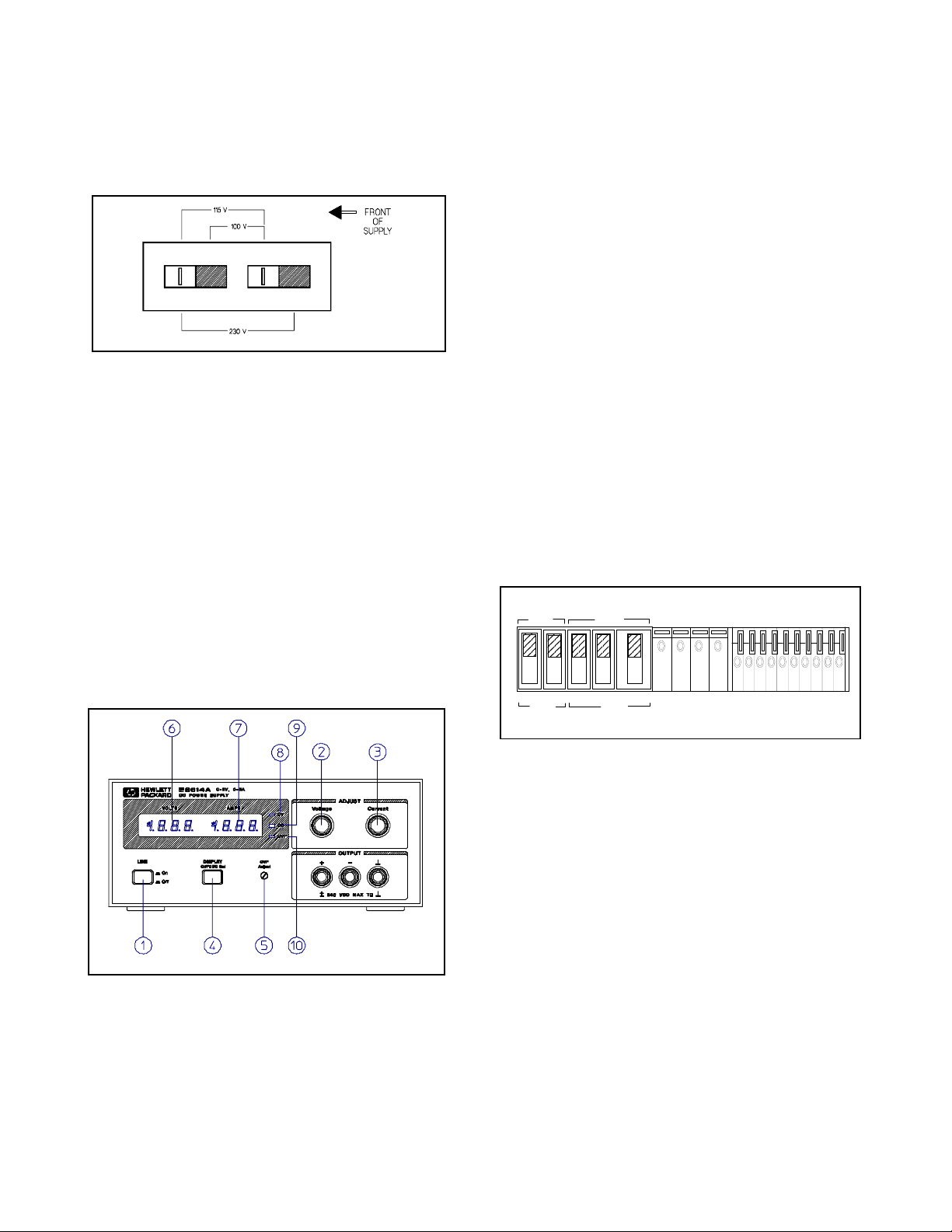
Line Voltage Option Conversion
Line voltage conversion is accomplished by adjusting two components: the line select switch and the rear panel fuse F1. To convert the suppl
as follows:
a. Disconnect power cord.
b. Turn off the suppl
cover upwards after takin
b
inserting a flat-blade screwdriver into the gap on the lower
rear portion of the cover.
c. Set two sections of the line volta
board for the desired line volta
d. Check the ratin
holder and replace with the correct fuse if necessar
and 115 V operation, use a normal blow 2 A fuse and for 230
V use a time dela
1-6
from one line voltage option to another, proceed
and remove the top cover by lifting the
of the fuse F1 installed in the rear panel fuse
1 A fuse.
e set for the unit at the factory. If
it off from both sides of the chassis
e selector switch on the PC
e (see Figure 2).
. For 100
e. Replace the cover and mark the suppl
y
g
g
g
gg
y
y
y
y
y
g
g
g
y
g
g
g
j
g
g
g
g
y
g
g
y
g
g
g
y
g
g
y
y
g
g
y
g
y
g
y
y
y
g
g
y
g
y
g
g
g
y
label indicatin
the correct line voltage and fuse that is in
clearly with a tag or
use.
Figure 2. Line Voltage Selector (set for 115 Vac)
Power Cord
To protect operating personnel, the instrument should be
rounded. This instrument is equipped with a three conductor
power cord. The third conductor is the
when the power cord is plu
the suppl
The power suppl
outlet used at
included, contact
is grounded.
was shipped with a power cord for the type of
our location. If the appropriate cord was not
our nearest HP Sales Office to obtain the cor-
ed into an appropriate receptacle,
rect cord.
round conductor and
4. DISPLAY OVP/CC SET Switch: Pressin
the VOLTS displa
shutdown (trip volta
current control set value. Settin
s or remote voltage programmed settings.
5.
settin
OVP Ad
ust Screwdriver Control:
to show voltage setting for overvoltage
e) and the AMPS display to show the
values are either front panel
PLAY OVP/CC SET switch, rotatin
with a small, flat-blade screwdriver increases the settin
overvolta
6. VOLTS Displa
OVP shutdown settin
AMPS Displa
7.
output-current settin
8. CV LED Indicator: Output volta
This means the power suppl
volta
e shutdown.
e mode.
: Di
ital display of actual output voltage, or
.
:
Di
ital display of actual output current, or
.
e is regulated when lighted.
is operating in the constant
9. CC LED Indicator: Output current is re
This means the power suppl
is operating in the constant cur-
this switch causes
While pressin
the DIS-
the control clock-wise
ulated when lighted.
for
rent mode.
10. OVP LED Indicator: Output is shutdown b
of an overvolta
volta
e and turning the power off, then on, resets the power
.
suppl
e when lighted. Removing the cause of over-
the occurrence
TURN-ON CHECKOUT PROCEDURE
The following checkout procedure describes the use of the front
panel controls and indicators illustrated in Fi
that the suppl
is operational:
ure 3 and ensures
OPERATING INSTRUCTIONS
INTRODUCTION
This section explains the operating controls and indicators and
provides information on man
instrument. The front panel controls and indicators are illustrated
in Fi
ure 3.
Figure 3. Front-Panel Controls and Indicators
LINE Switch:
1.
VOLTAGE Control:
2.
a
e.
CURRENT Control:
3.
Pressing this switch turns the supply on, or off.
rent.
operating modes possible with your
Clockwise rotation increases output volt-
Clockwise rotation increases output cur-
MASTER
M/S 1 M/S 2
SLAVE
LOCAL
CV CC SENSE
REMOTE
_
+
OUT+S-S
+
CV CC
+
__
VREF
A1 A2 A3 A4 A5
Figure 4. Switch Settings of Rear-Panel Control for Turn-
On Checkout
a. Disconnect power cord.
b. Check that the rear-panel switch settin
s are as shown in Fig-
ure 4.
c. Check that the rear panel label indicates that the suppl
to match
our input line voltage (If not, refer to "Line Voltage
is set
Option Conversion".).
d. Check that the fuse on the rear panel is correct for
volta
e.
our line
e. Connect the power cord and push the LINE switch to ON.
f. While pressin
OVP/CC SET switch, verify that the OVP
shutdown is set above 8.0, 20.0, 35.0, or 60.0 Vdc for
E3614A, E3615A, E3616A, or E3617A respectivel
. If not,
turn up OVP Adjust with a small flat-blade screwdriver.
. Turn VOLTAGE control fully counter clockwise to ensure that
the output of VOLTS displa
clockwise to ensure that output volta
mum output volta
h. While pressin
trol full
counter clockwise and then fully clockwise to ensure
e.
OVP/CC SET switch, turn the CURRENT con-
decreases to 0 Vdc, then fully
e increases to the maxi-
1-7

that the current limit value can be set from zero to maximum
g
y
g
g
g
g
g
g
y
y
g
g
y
g
y
y
y
y
g
g
y
g
g
g
g
y
g
y
g
y
y
g
g
y
y
g
g
j
g
y
y
g
g
g
g
y by
g
g
y
y
y
g
y
g
g
y
g
y g
y
y
y
g
g
g
g
g
g
rated value.
OPERATING MODES
The setting of the rear panel switch determines the operatin
modes of the power supply. The local operating mode is set so
the power suppl
terminals (local sensin
trols (local pro
e sensing and remote programming of output voltage and
volta
current usin
LOCAL OPERA TING MODE
The power supply is shipped from the factory configured in the
local operatin
settin
s of the rear panel, as shown in Figure 4. The power sup-
provides constant voltage(CV) or constant current(CC) output.
pl
Constant Voltage Operaton
To set up a power supply for constant voltage operation, proceed
as follows:
senses the output voltage directly at the output
) for operation using the front panel con-
ramming). Other operating modes are: remote
external voltages.
mode. Local operating mode requires the switch
False OVP shutdowns ma
too close to the suppl
down volta
a
e to avoid false shutdowns from load-induced transients.
Ad
down volta
a. With the VOLTAGE control full
b. While depressin
c. Follow the procedure for CC or CV operaton to set the out-
Resettin
turning power off. Wait one or more seconds, and turn power on
a
ain. If OVP shutdown continue to occur, check the connections
to the load and sense terminals, and check the OVP limit settin
e 4% of output +2.0 V or more above the output volt-
usting OVP.
the power suppl
the OVP Adjust control to the desired OVP shutdown usin
a small, flat-blade screwdriver.
put volta
Follow this procedure to adjust the OVP shut-
e.
e and current
OVP. If OVP shutdown occurs, reset the suppl
occur if you set the OVP shutdown
's operating voltage. Set the OVP shut-
counter clockwise, turn on
.
DISPLAY OVP/CC SET switch, adjust
..
a. Turn on the power suppl
trol for desired output volta
b. While depressin
turn CURRENT control for the desired current limit.
c. With power off connect the load to the output terminals.
d. Turn on the power suppl
actual operation, if a load change causes the current
Durin
limit to be exceeded, the power suppl
cross over to constant current mode and the output voltage
will drop proportionatel
and adjust 10-turn VOLTAGE con-
e (output terminals open).
DISPLAY OVP/CC SET switch, adjust 10-
. Verify that CV LED is lighted.
will automaticall
.
Constant Current Operation
To set up a power supply for constant current operation, proceed
as follows:
a. Turn on power suppl
b. While depressin
CURRENT control for the desired output current.
c. Turn up the VOLTAGE control to the desired volta
d. With power off connect the load to the output terminal.
e. Turn on power suppl
(If CV LED is li
settin
that is greater than the current setting multiplied by the
load resistance in ohms is required for CC operation.) Durin
actual operation, if a load chan
be exceeded, the power suppl
to constant volta
output current will drop proportionatel
.
DISPLAY OVP/CC SET switch, adjust
e limit.
and then verify that CC LED is lighted.
hted, choose a higher voltage limit. A voltage
e causes the voltage limit to
will automatically cross over
e operation at the preset voltage limit and
.
Overvoltage Protection (OVP)
Adjustable overvoltage protection guards your load against over-
e. When the voltage at the output terminals increases (or is
volta
increased b
set b
ables the output causin
zero. Durin
an external source) to the OVP shutdown voltage as
the OVP ADJUST control, the supply's OVP circuit dis-
the output voltage and current to drop to
OVP shutdown the OVP LED lights.
Strong electrostatic discharge to power supply can make
OVP trip and eventuall
effectivel
protect output loads from the hazardous ESD
crowbar the output, which can
current.
CONNECTING LOADS
The output of the supply is isolated from earth ground. Either output terminal ma
240 volts off
exceed 240 Vdc.
Each load should be connected to the power suppl
usin
separate pairs of connecting wires. This will minimize mutual
effects between loads and will retain full advantage of the
couplin
low output impedance of the power suppl
wires should be as short as possible and twisted or shielded to
reduce noise pick-up. (If a shield is used, connect one end to the
power suppl
ted.)
If load considerations require that the output power distribution
terminals be remotel
power suppl
distribution terminals via a pair of twisted or shielded wires and
each load separatel
nals. For this case, remote sensin
raph "Remote Voltage Sensing").
be grounded or the output can be floated up to
round. Total output voltage to ground must not
output terminals
. Each pair of connectin
round terminal and leave the other end unconnec-
located from the power supply, then the
output terminals should be connected to the remote
connected to the remote distribution termi-
should be used (See para-
OPERA TION BEYOND RATED OUTPUT
The output controls can adjust the voltage or current to values up
to 5% over the rated output. Althou
in the 5% overran
uaranteed to meet all of its performance specifications in this
ion.
re
e region without being damaged, it can not be
h the supply can be operated
1-8
 Loading...