


HP E1422A Remote Channel
HP 75000 Series C
Multi-function DAC Module
with
HP E1529A 32ch Remote Strain Conditioning Unit and
HP E1539A Remote Channel Signal Conditioning Plug-on
User’s and SCPI Programming Manual
Where to Find it - Online and Printed Information:
System installation (hardware/software)............VXIbus Configuration Guide*
HP VIC (VXI installation software)*
Getting Started with VXI Guide**
Module configuration and wiring.......................This Manual
SCPI programming.............................................This Manual
SCPI example programs........................ .... .... ... ..This Manual, Driver Disk
SCPI command reference ..................................This Manual
VXIplug&play programm ing ............................VXIplug&play Online Help
VXIplug&play example prog ra ms.....................VXIplug&play Online Help
VXIplug&play functio n refere nce................ ... ..VXIplug&play Online Help
Soft Front Panel information..............................VXIplug&play Online Help
VISA language information...............................HP VISA User’s Guide
HP VEE programming information ...................HP VEE User’s Manual
*Supplied with HP Command Modules , Embedded Control le rs, and VXLink
** Supplied with HP VXI Mainframes and on WEB at www.tmo.hp.com then search for “getting started with
vxi”. Search result will be “Getting Started With VXI Guide
”, click on this to download .PDF file.
Manual Part Number: E1422-90003
Printed in U.S . A . E0400


HEWLETT-PACKARD WARRANTY STATEMENT
HP PRODUCT: HP E1422A Remote Channel Multi-func tio n DAC Modu le with DURATION OF WARRANTY: 3 years
HP E1529A Remote Strain Conditioning Module and DURATION OF WARRANTY: 3 years
1. HP warrants HP hardware, accessori es and supplies against defects in mat erials and workmanship for the perio d specified above. If
HP receives notice o f such defects during the warranty period, HP wi ll, at its option, either repair or replace products which prove to be
defective. Replacement products may be either new or like-new.
2. HP warrants that HP software will not fail to execut e its programming instructions, for the perio d specified above, due to defects in
material and workmanship when properly installed and used. If HP receives notice of such defects during the warranty period, HP will
replace software media which does not execute its programming instructions due to such defects.
3. HP does not warrant that the operation of HP products will be interrupted or error free. If HP is unable, within a reasonable time, to
repair or replace any product to a condition as warranted, customer will be entitled to a refund of the purchase price upon prompt return
of the product.
4. HP products may con tain remanufactured parts equivalent to new in performance or m a y have been subject to incidental use.
5. The warranty period begins on the date of delivery or on the date of installation if installed by HP. If customer schedules or delays HP
installation more than 30 days after delivery, warranty begins on the 31st day from delivery.
6. Warranty does not apply to defects resulting from (a) improper or inadequate maintenance or calibration, (b) software, interfacing, parts
or supplies not supplied by HP, (c) unauthorized modification or misuse, (d) operation outside of the published environmental
specifications for the product, or (e) improper site preparation or maintenance.
7. TO THE EXTENT ALLOWED BY LOCAL LAW, THE ABOVE WARRANTIES ARE EXCLUSIVE AND NO OTHER
WARRANTY OR CONDITION, WHETHER WRITTEN OR ORAL, IS EXPRESSED OR IMPLIED AND HP SPECIFICALLY
DISCLAIMS ANY IMPLIED WARRANTY OR CONDITIONS OF MERCHANTABILITY, SATISFACTORY QUALITY, AND
FITNESS FOR A PARTICULAR PURPOSE.
8. HP will be liable for damage to tangible property per incident up to the greater of $300,000 or the actual amount paid for the product
that is the subject of the claim, an d for damages for bodily injury or death, to the extent that all such damages are determined by a court
of competent jurisdiction to have been directly caused by a defective HP product.
9. TO THE EXTENT ALLOWED BY LOCAL LAW, THE REMEDIES IN THIS WARRANTY STATEMENT ARE CUSTOMER’S
SOLE AND EXLUSIVE REMEDIES. EXCEPT AS INDICATED ABOVE, IN NO EVENT WILL HP OR ITS SUPPLIERS BE
LIABLE FOR LOSS OF DATA OR FOR DIRECT, SP ECIAL, INCIDENTAL, CONSEQUENTIAL (INCLUDING LOST PROFIT OR
DATA), OR OTHER DAMAGE, WHETHER BASED IN CONTRACT, TORT, OR OTHERWISE.
FOR CONSUMER TRANSACTIONS IN AUSTRALIA AND NEW ZEALAND: THE WARRANTY TERMS CONTAINED IN THIS
STATEMENT, EXCEPT TO THE EXTENT LAW FULLY PERM ITTED, DO NOT EXCLUDE, RESTRICT OR MODIFY AND AR E
IN ADDITION TO THE MANDATORY STATUTORY RIGHTS APPLICABLE TO THE SALE OF THIS PRODUCT TO YOU.
HP E1539A Remote Channel Signal Conditioning Plug-on and
all other applicable Signal Conditioning Plug-ons DURATION OF WARRANTY: 3 years
U.S. Government Restricted Rights
The Software and Documentation have been developed entirely at private expense. They are delivered and licensed as "commercial
computer software" as defined in DFARS 252.227- 7013 (Oct 1988), DFARS 252.211-7015 (May 1991) or DFARS 252.227-7014 (Jun
1995), as a "commercial item" as defined i n FAR 2.101(a), or as "R estricted computer software" as define d in FAR 52.227-19 (Jun
1987)(or any equivalent agency regulation or contract clause), whichever is applicable. You have only those rights provided for such
Software and Documentation by t he applicable FAR or DFARS clause or the HP st andard software agreement for the product involved.
HP E1422A Remote Channel DAC Unit User's Manual and SCPI Programming Guide
Copyright © 1998-2000 Hewlett-Packard Company. All Rights Reserved.
Edition 4
3

Documentation History
All Editions and Updates of t his manu al and th eir creati on da te are list ed belo w. The first Edition of the m anual is Ed ition 1. The Edition
number increments by 1 whenever the manual is revised. Updates, which are issued between Editions, contain replacement pages to
correct or add additional information to the current Edition of the manual. Whenever a new Edition is created, it will contain all of the
Update information for the previous E dition. Each new Edition or Update also inc ludes a revised c opy of this do cumentation history page.
Edition 1 . . . . . . . . . . . . . . . . . . . . . . . . . . . . . . . . . . . . . . . . . . . . . . . .May 1999
Edition 2 . . . . . . . . . . . . . . . . . . . . . . . . . . . . . . . . . . . . . . . . . . . . . . . .July 1999
Edition 3 . . . . . . . . . . . . . . . . . . . . . . . . . . . . . . . . . . . . . . . . . . .September 1999
Edition 4 . . . . . . . . . . . . . . . . . . . . . . . . . . . . . . . . . . . . . . . . . . . . February 2000
Safety Symbols
product. Indicates that the user must refer to
the manual for specific WARNING or
CAUTION information to av oid personal
injury or damage to the product.
Indicates the field wiring te rminal that must
be connected to earth ground be fore
operating the equipmentÅprotects against
electrical shock in case of fault.
or
Frame or chassis ground terminal—
typically connects t o the e quipmen t's me tal
WARNING
CAUTION
Alternating current (AC)Instruction manual symbol affixed to
Direct current (DC).
Indicates hazardous voltages.
Calls attention to a procedure, practice, or
condition that could cause bodily injury or
death.
Calls attention to a procedure, practice, or
condition that could possibly cause damage to
equipment or perm anent loss of data.
WARNINGS
The following general safety precauti ons must be observed during all phases of operation, service, and repair of this product. Failure to
comply with these precautions or with specific warnings elsewhere in this manual violates safety standards of design, manufacture, and
intended use of the product. Hewlett-Packard Com pany assumes no liability for the customer's failure to comply with these requirements.
Ground the equipment: For Safety Class 1 equipment (equipment having a protective earth terminal), an uninterruptible safety earth
ground must be provided from the mains power source to the product input wiring terminals or supplied power cable.
DO NOT operate the product in an explosive atmosphere or in the presence of flammable gases or fumes.
For continued protection against fire, replace the line fuse(s) only with fuse(s) of the same voltage and current rating and type. DO NOT
use repaired fuses or short-circuited fuse holders.
Keep away from live circuits: Operating personnel must not remove equipment covers or shields. Procedures involving the removal of
covers or shields are for use by service-trained personnel only. Under certain conditions, dangerous voltages may exist even with the
equipment sw itche d off. To av oid danger ous ele ctric al sh ock, DO NOT perfor m pro cedure s inv olving cover or shi eld remova l unles s you
are qualified to do so.
DO NOT operate damaged equipmen t: Whenever it is possible that the safety protection features built into this product have been
impaired, either through physical damage, excessive moisture, or any other reason, REMO VE POWER and do not use the product until
safe operation can be verified by service-trained personnel. If necessary, return the product to a Hewlett-Packard Sales and Service Office
for service and repair to ensure that safety features are maintained.
DO NOT service or adjust alone: Do not attempt internal service or adjustment unless another person, capable of rendering first aid and
resuscitation, is present.
DO NOT substitute parts or modify equipment: Becaus e of th e dang er of introd ucing addition al haz ards, do not i nstall subst itute pa rts
or perform any unauthorized modification to the product. Return the product to a Hewlett-Packard Sales and Service Office for service
and repair to ensure that safety features are maintained.
Operating Location: Sheltered loc a tio n whe re air tempera tu re and hu m idit y are co ntro lled within thi s pro duc t’s specifica tio ns and the
product is protected against direct exposur e to clim at ic cond itio ns such as direc t sunli ght, wind , rain, snow, sleet, and icing, water spray
or splash, hoarfrost or dew. (Typically, indoor.) Pollution envir onment for which this product may be operated is IEC 664 Pollution d egree
2.
CLEANING THE FRONT PANEL AND TOP/BOTTOM SHIELDS: Clean the outside surfaces of this module with a cloth slightly
dampened with water. Do not attempt to clean the interior of this module.
4

Declaration of Conformity
according to ISO/IEC Guide 22 and EN 45014
Manufacturer’s Name: Hewlett-Packard Company
Loveland Manufacturing Center
Manufacturer’s Address: 815 14th Street S.W.
Loveland, Colorado 80537
declares, that the product:
Product Names: Remote Channel Multi-function DAC Module
Remote Channel Signal Conditioning Plug-on
32-ch Remote Strain Conditioning Unit
Model Numbers: HP E1422A
HP E1539A
HP E1529A
Product Options: All options and all other applicable Signal Conditioning Plug-ons
conforms to the following Product Specifications:
Safety: IEC 1010-1 (1990) Incl. Amend 2 (1996)/EN61010-1 (1993)
CSA C22.2 #1010.1 (1992)
UL 3111-1 (1994)
EMC: CISPR 11:1990/EN55011 (1991): Group 1 Class A
EN61000-3-2:1995 Class A
EN61000-3-3:1995
EN50082-1:1992
IEC 1000-4-2:1995: 4kVCD, 8kVAD
IEC 1000-4-3:1995: 3 V/m
IEC 1000-4-4:1995: 1kV Power Line 0.5kV Signal Lines
ENV50141:1993/prEN50082-1 (1995): 3 Vrms
EN 61000-4-5:1995 1kV CM, 0.5kV DM
EN61000-4-8:1993/prEN50082-1 (1995): 3 A/M
EN61000-4-11:1994/prEN50082-1 (1995): 30%, 10mS 60%, 100mS
Supplementary Information: The product herewith complies with the requirements of the Low Voltage Directive
73/23/EEC and the EMC Directive 89/336/EEC (inclusive 93/68/EEC) and carries the "CE" mark accordingly.
May 3, 1999 Jim White, QA Manager
For Compliance In f ormation ONLY, contact:
Australia Contact
Victoria 3130, Australia
: Product Regulations Manager, Hewlett-Packard Australia Ltd., 31-41 Joseph Street, Blackburn,
European Contact:
Standards Europe, Herrenberger Straβe 130, D-71034 Boblingen (FAX: +49- 7031-14-3143)
USA Contact:
80537
Your local Hewlett-Packard Sales and Service Office or Hewlett-Packard GmbH, Department HQ-TRE,
Product Regulations Manager, Hewlett-Packard Company, P.O. Box 301, Mail Stop BU212, Loveland, CO
5

Notes:
6

Pl
ease fold and tape for ma
ili
ng
Reader Comment Sheet
HP E1422A Remote Channel Multifunction DAC Module User’s Manual
Edition 4
You can help us improve our manuals by sharing your commen ts and sug gestions. In appreciation of your time, we will
enter you in a quarterly drawing for a Hewlett-Packard Palmtop Personal Computer (U.S. government employees
are not eligible for the drawing).
Your Name
Company Name
Job Title
Address
City, State/Province
Country
Zip/Postal Code
Telephone Number with Area Code
Please list the system controller, operating system, programming language, and plug-in modules you are using.
fold here
BUSINESS REPLY MAIL
FIRST CLASS PERMIT NO. 37 LOVELAND, CO
POSTAGE WILL BE PAID BY ADDRESSEE
cut along this li ne
HEWLETT-PACKARD COMPANY
Measurement Systems Division
Learning Products Department
P.O. Box 301
Loveland, CO 80539-9984
NO POSTAGE
NECESSARY
IF MAILED
IN THE
UNITED STATES
fold here
Please pencil-in one circle for each statement below: Disagree Agree
• The documentation is well organized. OOOOO
•Instructions are easy to understand. OOOOO
The documentation is clearly written. OOOOO
•
Examples are clear and useful. OOOOO
•
•Illustrations are clear and helpful. OOOOO
The documentation meets my overall expectations. OOOOO
•
Please write any comments or suggestions below–be specific.


Content s
HP E1422A Remote Channel Multifunction DAC Module (Edition 3)
HEWLETT-PACKARD WARRANTY STATEMENT. . . . . . . . . . . . . . . . . . . . . 3
Safety Symbols . . . . . . . . . . . . . . . . . . . . . . . . . . . . . . . . . . . . . . . . . . . . . . . . . . . . . . 4
WARNINGS. . . . . . . . . . . . . . . . . . . . . . . . . . . . . . . . . . . . . . . . . . . . . . . . . . . . . . . . 4
Declaration of Conformity . . . . . . . . . . . . . . . . . . . . . . . . . . . . . . . . . . . . . . . . . . . . 5
Reader Comment Sheet. . . . . . . . . . . . . . . . . . . . . . . . . . . . . . . . . . . . . . . . . . . . . . . 7
Contents . . . . . . . . . . . . . . . . . . . . . . . . . . . . . . . . . . . . . . . . . . . . . . . . . . . . . . . . . . . . . . 9
Chapter 1
Getting Started . . . . . . . . . . . . . . . . . . . . . . . . . . . . . . . . . . . . . . . . . . . . . . . . . . . . . . 21
About this Chapter . . . . . . . . . . . . . . . . . . . . . . . . . . . . . . . . . . . . . . . . . . . . . . . . . 21
Configuring the HP E1422. . . . . . . . . . . . . . . . . . . . . . . . . . . . . . . . . . . . . . . . . . . 21
Setting the Logical Address Switch . . . . . . . . . . . . . . . . . . . . . . . . . . . . . . . . 22
Installing Signal Conditioning Plug-ons . . . . . . . . . . . . . . . . . . . . . . . . . . . . . 23
Disabling the Input Protect Feature (optional) . . . . . . . . . . . . . . . . . . . . . . . 27
Disabling Flash Memory Access (optio nal) . . . . . . . . . . . . . . . . . . . . . . . . . . 27
Installing the Module. . . . . . . . . . . . . . . . . . . . . . . . . . . . . . . . . . . . . . . . . . . . . . . . 29
Instrument Drivers . . . . . . . . . . . . . . . . . . . . . . . . . . . . . . . . . . . . . . . . . . . . . . . . . 29
About Example Programs. . . . . . . . . . . . . . . . . . . . . . . . . . . . . . . . . . . . . . . . . . . . 29
Verifying a Successful Configuration . . . . . . . . . . . . . . . . . . . . . . . . . . . . . . . . . . 30
Chapter 2
Field Wiring . . . . . . . . . . . . . . . . . . . . . . . . . . . . . . . . . . . . . . . . . . . . . . . . . . . . . . . . 33
About This Chapter. . . . . . . . . . . . . . . . . . . . . . . . . . . . . . . . . . . . . . . . . . . . . . . . . 33
Planning Your Wiring Layout . . . . . . . . . . . . . . . . . . . . . . . . . . . . . . . . . . . . . . . . 33
SCP Positions and Channel Numbers . . . . . . . . . . . . . . . . . . . . . . . . . . . . . . 33
Sense SCPs and Output SCPs . . . . . . . . . . . . . . . . . . . . . . . . . . . . . . . . . . . . . 35
Planning for Thermocouple Measurements . . . . . . . . . . . . . . . . . . . . . . . . . 36
Faceplate Connector Pin-Signal Lists . . . . . . . . . . . . . . . . . . . . . . . . . . . . . . . . . . 37
Optional Terminal and Connector Modules. . . . . . . . . . . . . . . . . . . . . . . . . . . . . 38
The SCPs and Terminal Module . . . . . . . . . . . . . . . . . . . . . . . . . . . . . . . . . . . 38
Terminal Module Layout . . . . . . . . . . . . . . . . . . . . . . . . . . . . . . . . . . . . . . . . . 38
The RJ-45 Connector Module . . . . . . . . . . . . . . . . . . . . . . . . . . . . . . . . . . . . . 39
Spring Terminal Module Layout . . . . . . . . . . . . . . . . . . . . . . . . . . . . . . . . . . 39
Screw Terminal Module Layout . . . . . . . . . . . . . . . . . . . . . . . . . . . . . . . . . . . 41
Reference Temperature Sensing with the HP E1422 . . . . . . . . . . . . . . . . . . . . . . 42
Preferred Measurement Connections . . . . . . . . . . . . . . . . . . . . . . . . . . . . . . . . . . 44
Contents 9

Connecting the On-board Thermistor. . . . . . . . . . . . . . . . . . . . . . . . . . . . . . . . . . 47
Wiring and Attaching the Terminal Module . . . . . . . . . . . . . . . . . . . . . . . . . . . . 48
Removing the HP E1422 Terminal Modules. . . . . . . . . . . . . . . . . . . . . . . . . . . . . 50
Attaching and Removing the HP E1422 RJ-45 Module. . . . . . . . . . . . . . . . . . . . 51
Adding Components to the Terminal Module . . . . . . . . . . . . . . . . . . . . . . . . . . . 52
Spring and Screw Terminal Module Wiring Maps . . . . . . . . . . . . . . . . . . . . . . . 53
Chapter 3
Programming the HP E1422A & HP E1529A for Remote Strain Measurement . 55
About This Chapter. . . . . . . . . . . . . . . . . . . . . . . . . . . . . . . . . . . . . . . . . . . . . . . . . 55
Instrument Setup for Remote Strain Measurements . . . . . . . . . . . . . . . . . . . . . . 56
Preparing the HP E1422A for Installation . . . . . . . . . . . . . . . . . . . . . . . . . . 56
Overview . . . . . . . . . . . . . . . . . . . . . . . . . . . . . . . . . . . . . . . . . . . . . . . . . . . . . . 56
Preparing the HP E1529A for Use . . . . . . . . . . . . . . . . . . . . . . . . . . . . . . . . . 57
Installing User Selected 1/4 Bridge Resistors (optional) . . . . . . . . . . . . . . . . 57
Connecting HP E1529As to the HP E1422A . . . . . . . . . . . . . . . . . . . . . . . . . 60
Two Interconnect Methods . . . . . . . . . . . . . . . . . . . . . . . . . . . . . . . . . . . . . . . 61
Connecting Excitation Supplies . . . . . . . . . . . . . . . . . . . . . . . . . . . . . . . . . . . 65
Connecting the HP E1529A to Strain Gages. . . . . . . . . . . . . . . . . . . . . . . . . . . . . 66
Channel Connector Pin-to-Signal Relationship . . . . . . . . . . . . . . . . . . . . . . 66
HP E1529A Bridge Configurations . . . . . . . . . . . . . . . . . . . . . . . . . . . . . . . . . . . . 67
Connecting to the HP E1529A’s Dynamic Strain Ports. . . . . . . . . . . . . . . . . . . . 70
Extending the Dynamic Strain Connection . . . . . . . . . . . . . . . . . . . . . . . . . . 70
Dynamic Strain Port Offset Control . . . . . . . . . . . . . . . . . . . . . . . . . . . . . . . . 72
Remote Strain Channel Addressing. . . . . . . . . . . . . . . . . . . . . . . . . . . . . . . . . . . . 73
Runtime Remote Scan Verification . . . . . . . . . . . . . . . . . . . . . . . . . . . . . . . . 73
Programming for Remote Strain Measurement. . . . . . . . . . . . . . . . . . . . . . . . . . 75
Description of Strain Measurement . . . . . . . . . . . . . . . . . . . . . . . . . . . . . . . . 75
Verifying Correct Bridge Completion (Shunt Cal) . . . . . . . . . . . . . . . . . . . . . . . 87
Built-in Strain Conversion Equations . . . . . . . . . . . . . . . . . . . . . . . . . . . . . . . . . . 89
Chapter 4
Programming the HP E1422A for
Data Acquisition and Control . . . . . . . . . . . . . . . . . . . . . . . . . . . . . . . . . . . . . . . . . . 91
About This Chapter . . . . . . . . . . . . . . . . . . . . . . . . . . . . . . . . . . . . . . . . . . . . . 91
Overview of the HP E1422A Multifunction DAC Module. . . . . . . . . . . . . . . . . . 92
Multifunction DAC? . . . . . . . . . . . . . . . . . . . . . . . . . . . . . . . . . . . . . . . . . . . . 93
Operational Overview . . . . . . . . . . . . . . . . . . . . . . . . . . . . . . . . . . . . . . . . . . . 94
Detailed Instrument Operation Cycle . . . . . . . . . . . . . . . . . . . . . . . . . . . . . . 96
Programming Model . . . . . . . . . . . . . . . . . . . . . . . . . . . . . . . . . . . . . . . . . . . . . . . . 98
Executing the Programming Model . . . . . . . . . . . . . . . . . . . . . . . . . . . . . . . . . . . 99
Power-on and *RST Default Settings . . . . . . . . . . . . . . . . . . . . . . . . . . . . . . 100
Setting up Analog Input and Output Channels . . . . . . . . . . . . . . . . . . . . . . . . . 103
10 Contents

Configuring Programmable Analog SCP Parameters . . . . . . . . . . . . . . . . 103
Linking Input Channels to EU Conversion . . . . . . . . . . . . . . . . . . . . . . . . . 105
Linking Output Channels to Functions . . . . . . . . . . . . . . . . . . . . . . . . . . . . 113
Setting up Digital Input and Output Channels. . . . . . . . . . . . . . . . . . . . . . . . . . 113
Setting up Digital Inputs . . . . . . . . . . . . . . . . . . . . . . . . . . . . . . . . . . . . . . . . 113
Setting up Digital Outputs . . . . . . . . . . . . . . . . . . . . . . . . . . . . . . . . . . . . . . . 114
Performing Channel Calibration (Important!). . . . . . . . . . . . . . . . . . . . . . . . . . 117
Calibrationg the HP E1422A . . . . . . . . . . . . . . . . . . . . . . . . . . . . . . . . . . . . . 117
Calibrating Remote Signal Conditioning Units . . . . . . . . . . . . . . . . . . . . . . 118
Defining an Analog Input Scan List (ROUT:SEQ:DEF). . . . . . . . . . . . . . . . . . 119
Defining C Language Algorithms. . . . . . . . . . . . . . . . . . . . . . . . . . . . . . . . . . . . . 120
Global variable definition . . . . . . . . . . . . . . . . . . . . . . . . . . . . . . . . . . . . . . . 120
Algorithm definition . . . . . . . . . . . . . . . . . . . . . . . . . . . . . . . . . . . . . . . . . . . . 121
Pre-setting Algorithm Variables . . . . . . . . . . . . . . . . . . . . . . . . . . . . . . . . . . 121
Defining Data Storage . . . . . . . . . . . . . . . . . . . . . . . . . . . . . . . . . . . . . . . . . . . . . . 122
Specifying th e
Data Format . . . . . . . . . . . . . . . . . . . . . . . . . . . . . . . . . . . . . . . . . . . . . . . . . . 122
Selecting the
FIFO Mode . . . . . . . . . . . . . . . . . . . . . . . . . . . . . . . . . . . . . . . . . . . . . . . . . . 123
Setting up the Trigger System . . . . . . . . . . . . . . . . . . . . . . . . . . . . . . . . . . . . . . . 123
Arm and Trigger Sources . . . . . . . . . . . . . . . . . . . . . . . . . . . . . . . . . . . . . . . 123
Programming the Trigger Timer . . . . . . . . . . . . . . . . . . . . . . . . . . . . . . . . . 125
Setting the Trigger Counter . . . . . . . . . . . . . . . . . . . . . . . . . . . . . . . . . . . . . 126
Sending Trigger Signals to
Other Instruments . . . . . . . . . . . . . . . . . . . . . . . . . . . . . . . . . . . . . . . . . . . . . 126
INITiating the Module/Starting Scanning and Algorithms. . . . . . . . . . . . . . . . 126
Starting Scanning and/or Algorithms . . . . . . . . . . . . . . . . . . . . . . . . . . . . . 127
The Operating Sequence . . . . . . . . . . . . . . . . . . . . . . . . . . . . . . . . . . . . . . . . 127
Reading Running Algorithm Values . . . . . . . . . . . . . . . . . . . . . . . . . . . . . . . . . . 128
Modifying Running Algorithm Variables . . . . . . . . . . . . . . . . . . . . . . . . . . . . . . 132
Updating the Algorithm Variables and Coefficients . . . . . . . . . . . . . . . . . . 132
Enabling and Disabling Algorithms . . . . . . . . . . . . . . . . . . . . . . . . . . . . . . . 133
Setting Algorithm Execution Frequency . . . . . . . . . . . . . . . . . . . . . . . . . . . 134
Example SCPI Command Sequence . . . . . . . . . . . . . . . . . . . . . . . . . . . . . . . . . . 134
Example VXIplug&play Driver Function Sequence . . . . . . . . . . . . . . . . . . . . . 135
Using the Status System . . . . . . . . . . . . . . . . . . . . . . . . . . . . . . . . . . . . . . . . . . . . 137
Enabling Events to be Reported in the Status Byte . . . . . . . . . . . . . . . . . . 140
Reading the Status Byte . . . . . . . . . . . . . . . . . . . . . . . . . . . . . . . . . . . . . . . . . 141
Clearing the Enable Registers . . . . . . . . . . . . . . . . . . . . . . . . . . . . . . . . . . . . 142
The Status Byte Group’s Enable Register . . . . . . . . . . . . . . . . . . . . . . . . . . 142
Reading Status Groups Directly . . . . . . . . . . . . . . . . . . . . . . . . . . . . . . . . . . 142
HP E1422 Background Operation . . . . . . . . . . . . . . . . . . . . . . . . . . . . . . . . . . . . 143
Updating the Status System and VXIbus Interrupts . . . . . . . . . . . . . . . . . . . . . 143
Creating and Loading Custom EU Conversion Tables . . . . . . . . . . . . . . . . . . . 145
Contents 11

Compensating for System Offsets . . . . . . . . . . . . . . . . . . . . . . . . . . . . . . . . . . . . 148
Special Considerations . . . . . . . . . . . . . . . . . . . . . . . . . . . . . . . . . . . . . . . . . . 149
Detecting Open Transducers . . . . . . . . . . . . . . . . . . . . . . . . . . . . . . . . . . . . . . . . 150
More On Auto Ranging. . . . . . . . . . . . . . . . . . . . . . . . . . . . . . . . . . . . . . . . . . . . . 151
Settling Characteristics. . . . . . . . . . . . . . . . . . . . . . . . . . . . . . . . . . . . . . . . . . . . . 152
Background . . . . . . . . . . . . . . . . . . . . . . . . . . . . . . . . . . . . . . . . . . . . . . . . . . . 152
Checking for Problems . . . . . . . . . . . . . . . . . . . . . . . . . . . . . . . . . . . . . . . . . 152
Fixing the Problem . . . . . . . . . . . . . . . . . . . . . . . . . . . . . . . . . . . . . . . . . . . . . 153
Chapter 5
Creating and Running Algorithms . . . . . . . . . . . . . . . . . . . . . . . . . . . . . . . . . . . . . 155
About This Chapter. . . . . . . . . . . . . . . . . . . . . . . . . . . . . . . . . . . . . . . . . . . . . . . . 155
Overview of the Algorithm Language . . . . . . . . . . . . . . . . . . . . . . . . . . . . . . . . . 156
Example Language Usage . . . . . . . . . . . . . . . . . . . . . . . . . . . . . . . . . . . . . . . 157
The Algorithm Execution Environment . . . . . . . . . . . . . . . . . . . . . . . . . . . . . . . 158
The Main Function . . . . . . . . . . . . . . . . . . . . . . . . . . . . . . . . . . . . . . . . . . . . . 158
How Your Algorithms Fit In . . . . . . . . . . . . . . . . . . . . . . . . . . . . . . . . . . . . . 158
Accessing the E1422’s Resources . . . . . . . . . . . . . . . . . . . . . . . . . . . . . . . . . . . . . 159
Accessing I/O Channels . . . . . . . . . . . . . . . . . . . . . . . . . . . . . . . . . . . . . . . . . 160
Accessing Remote Scan Status Variables . . . . . . . . . . . . . . . . . . . . . . . . . . . 161
Runtime Remote Scan Verification . . . . . . . . . . . . . . . . . . . . . . . . . . . . . . . 161
Defining and Accessing Global Variables . . . . . . . . . . . . . . . . . . . . . . . . . . 163
Determining
First Execution (First_loop) . . . . . . . . . . . . . . . . . . . . . . . . . . . . . . . . . . . . . 164
Initializing Variables . . . . . . . . . . . . . . . . . . . . . . . . . . . . . . . . . . . . . . . . . . . 164
Sending Data to the CVT and FIFO . . . . . . . . . . . . . . . . . . . . . . . . . . . . . . . 165
Setting a VXIbus Interrupt . . . . . . . . . . . . . . . . . . . . . . . . . . . . . . . . . . . . . . 166
Determining Your Algorithm’s Identity (ALG_NUM) . . . . . . . . . . . . . . . . 166
Calling User Defined Functions . . . . . . . . . . . . . . . . . . . . . . . . . . . . . . . . . . 166
Operating Sequence. . . . . . . . . . . . . . . . . . . . . . . . . . . . . . . . . . . . . . . . . . . . . . . . 167
Overall Sequence . . . . . . . . . . . . . . . . . . . . . . . . . . . . . . . . . . . . . . . . . . . . . . 167
Algorithm Execution Order . . . . . . . . . . . . . . . . . . . . . . . . . . . . . . . . . . . . . 168
12 Contents
Defining Algorithms (ALG:DEF). . . . . . . . . . . . . . . . . . . . . . . . . . . . . . . . . . . . . 170
ALG:DEFINE in the Programming Sequence . . . . . . . . . . . . . . . . . . . . . . 170
ALG:DEFINE’s Thre e Data Formats . . . . . . . . . . . . . . . . . . . . . . . . . . . . . 170
Changing an Algorithm While
it’s Running . . . . . . . . . . . . . . . . . . . . . . . . . . . . . . . . . . . . . . . . . . . . . . . . . . . 171
A Very Simple First Algorithm . . . . . . . . . . . . . . . . . . . . . . . . . . . . . . . . . . . . . . 174
Writing the Algorithm . . . . . . . . . . . . . . . . . . . . . . . . . . . . . . . . . . . . . . . . . . 174
Running the Algorithm . . . . . . . . . . . . . . . . . . . . . . . . . . . . . . . . . . . . . . . . . 174
Modifying an Example PID Algorithm . . . . . . . . . . . . . . . . . . . . . . . . . . . . . . . . 174
PIDA with digital On-Off Control . . . . . . . . . . . . . . . . . . . . . . . . . . . . . . . . 174
Algorithm to Algorithm Communication . . . . . . . . . . . . . . . . . . . . . . . . . . . . . . 175
Communication Using Channel Identifiers . . . . . . . . . . . . . . . . . . . . . . . . . 175
Communication Using Global Variables . . . . . . . . . . . . . . . . . . . . . . . . . . . 176

Non-Control Algorithms. . . . . . . . . . . . . . . . . . . . . . . . . . . . . . . . . . . . . . . . . . . . 178
Process Monitoring Algorithm . . . . . . . . . . . . . . . . . . . . . . . . . . . . . . . . . . . 178
Implementing Setpoint Profiles . . . . . . . . . . . . . . . . . . . . . . . . . . . . . . . . . . . . . . 178
Algorithm Language Reference . . . . . . . . . . . . . . . . . . . . . . . . . . . . . . . . . . . . . . 181
Standard Reserved Keywords . . . . . . . . . . . . . . . . . . . . . . . . . . . . . . . . . . . . 181
Special HP E1422 Reserved Keywords . . . . . . . . . . . . . . . . . . . . . . . . . . . . 181
Identifiers . . . . . . . . . . . . . . . . . . . . . . . . . . . . . . . . . . . . . . . . . . . . . . . . . . . . 181
Special Identifiers for Channels . . . . . . . . . . . . . . . . . . . . . . . . . . . . . . . . . . 182
Special Identifiers for Remote Scan Status . . . . . . . . . . . . . . . . . . . . . . . . . 182
Operators . . . . . . . . . . . . . . . . . . . . . . . . . . . . . . . . . . . . . . . . . . . . . . . . . . . . 182
Intrinsic Functions and Statements . . . . . . . . . . . . . . . . . . . . . . . . . . . . . . . 183
Program Flow Control . . . . . . . . . . . . . . . . . . . . . . . . . . . . . . . . . . . . . . . . . . 183
Data Types . . . . . . . . . . . . . . . . . . . . . . . . . . . . . . . . . . . . . . . . . . . . . . . . . . . 184
Data Structures . . . . . . . . . . . . . . . . . . . . . . . . . . . . . . . . . . . . . . . . . . . . . . . . 185
Bitfield Access . . . . . . . . . . . . . . . . . . . . . . . . . . . . . . . . . . . . . . . . . . . . . . . . . 185
Language Syntax Summary . . . . . . . . . . . . . . . . . . . . . . . . . . . . . . . . . . . . . . . . . 186
Program Structure and Syntax . . . . . . . . . . . . . . . . . . . . . . . . . . . . . . . . . . . . . . 190
Declaring Variables . . . . . . . . . . . . . . . . . . . . . . . . . . . . . . . . . . . . . . . . . . . . 190
Assigning Values . . . . . . . . . . . . . . . . . . . . . . . . . . . . . . . . . . . . . . . . . . . . . . . 191
The Operations Symbols . . . . . . . . . . . . . . . . . . . . . . . . . . . . . . . . . . . . . . . . 191
Conditional Execution . . . . . . . . . . . . . . . . . . . . . . . . . . . . . . . . . . . . . . . . . . 192
Comment Lines . . . . . . . . . . . . . . . . . . . . . . . . . . . . . . . . . . . . . . . . . . . . . . . . 193
Overall Program Structure . . . . . . . . . . . . . . . . . . . . . . . . . . . . . . . . . . . . . . 194
Chapter 6
HP E1422 Command Reference . . . . . . . . . . . . . . . . . . . . . . . . . . . . . . . . . . . . . . . 195
Using This Chapter . . . . . . . . . . . . . . . . . . . . . . . . . . . . . . . . . . . . . . . . . . . . . . . . 195
Overall Command Index . . . . . . . . . . . . . . . . . . . . . . . . . . . . . . . . . . . . . . . . . . . 195
Command Fundamentals . . . . . . . . . . . . . . . . . . . . . . . . . . . . . . . . . . . . . . . . . . . 201
Common Command Format . . . . . . . . . . . . . . . . . . . . . . . . . . . . . . . . . . . . . 201
SCPI Command Format . . . . . . . . . . . . . . . . . . . . . . . . . . . . . . . . . . . . . . . . 201
Linking Commands . . . . . . . . . . . . . . . . . . . . . . . . . . . . . . . . . . . . . . . . . . . . 206
Data Types . . . . . . . . . . . . . . . . . . . . . . . . . . . . . . . . . . . . . . . . . . . . . . . . . . 206
SCPI Command Reference. . . . . . . . . . . . . . . . . . . . . . . . . . . . . . . . . . . . . . . . . . 208
ABORt . . . . . . . . . . . . . . . . . . . . . . . . . . . . . . . . . . . . . . . . . . . . . . . . . . . . . . . . . . 209
ALGorithm. . . . . . . . . . . . . . . . . . . . . . . . . . . . . . . . . . . . . . . . . . . . . . . . . . . . . . . 210
ALGorithm[:EXPLicit]:ARRay . . . . . . . . . . . . . . . . . . . . . . . . . . . . . . . . . . 210
ALGorithm[:EXPLicit]:ARRay? . . . . . . . . . . . . . . . . . . . . . . . . . . . . . . . . . 211
ALGorithm[:EXPLicit]:DEFine . . . . . . . . . . . . . . . . . . . . . . . . . . . . . . . . . . 212
ALGorithm[:EXPLicit]:SCALar . . . . . . . . . . . . . . . . . . . . . . . . . . . . . . . . . 216
ALGorithm[:EXPLicit]:SCALar? . . . . . . . . . . . . . . . . . . . . . . . . . . . . . . . . 217
ALGorithm[:EXPLicit]:SCAN:RATio . . . . . . . . . . . . . . . . . . . . . . . . . . . . 217
ALGorithm[:EXPLicit]:SCAN:RATio? . . . . . . . . . . . . . . . . . . . . . . . . . . . 218
ALGorithm[:EXPLicit]:SIZE? . . . . . . . . . . . . . . . . . . . . . . . . . . . . . . . . . . . 218
ALGorithm[:EXPLicit][:STATe] . . . . . . . . . . . . . . . . . . . . . . . . . . . . . . . . . 219
ALGorithm[:EXPLicit][:STATe]? . . . . . . . . . . . . . . . . . . . . . . . . . . . . . . . . 220
ALGorithm[:EXPLicit]:TIME? . . . . . . . . . . . . . . . . . . . . . . . . . . . . . . . . . . 220
Contents 13

ALGorithm:FUNCtion:DEFine . . . . . . . . . . . . . . . . . . . . . . . . . . . . . . . . . . 221
ALGorithm:OUTPut:DELay . . . . . . . . . . . . . . . . . . . . . . . . . . . . . . . . . . . . 222
ALGorithm:OUTPut:DELay? . . . . . . . . . . . . . . . . . . . . . . . . . . . . . . . . . . . 223
ALGorithm:UPDate[:IMMediate] . . . . . . . . . . . . . . . . . . . . . . . . . . . . . . . . 224
ALGorithm:UPDate:CHANnel . . . . . . . . . . . . . . . . . . . . . . . . . . . . . . . . . . . 225
ALGorithm:UPDate:WINDow . . . . . . . . . . . . . . . . . . . . . . . . . . . . . . . . . . . 226
ALGOrithm:UPDate:WINDow? . . . . . . . . . . . . . . . . . . . . . . . . . . . . . . . . . 227
ARM . . . . . . . . . . . . . . . . . . . . . . . . . . . . . . . . . . . . . . . . . . . . . . . . . . . . . . . . . . . . 228
ARM[:IMMediate] . . . . . . . . . . . . . . . . . . . . . . . . . . . . . . . . . . . . . . . . . . . . . 229
ARM:SOURce . . . . . . . . . . . . . . . . . . . . . . . . . . . . . . . . . . . . . . . . . . . . . . . . 229
ARM:SOURce? . . . . . . . . . . . . . . . . . . . . . . . . . . . . . . . . . . . . . . . . . . . . . . . 230
CALibration. . . . . . . . . . . . . . . . . . . . . . . . . . . . . . . . . . . . . . . . . . . . . . . . . . . . . . 231
CALibration:CONFigure:RESistance . . . . . . . . . . . . . . . . . . . . . . . . . . . . 232
CALibration:CONFigure:VOLTage . . . . . . . . . . . . . . . . . . . . . . . . . . . . . . 233
CALibration:REMote? . . . . . . . . . . . . . . . . . . . . . . . . . . . . . . . . . . . . . . . . . 234
CALibration:REMote:DATA . . . . . . . . . . . . . . . . . . . . . . . . . . . . . . . . . . . . 235
CALibration:REMote:DATA? . . . . . . . . . . . . . . . . . . . . . . . . . . . . . . . . . . . 235
CALibration:REMote:STORe . . . . . . . . . . . . . . . . . . . . . . . . . . . . . . . . . . . 236
CALibration:SETup . . . . . . . . . . . . . . . . . . . . . . . . . . . . . . . . . . . . . . . . . . . 236
CALibration:SETup? . . . . . . . . . . . . . . . . . . . . . . . . . . . . . . . . . . . . . . . . . . 237
CALibration:STORe . . . . . . . . . . . . . . . . . . . . . . . . . . . . . . . . . . . . . . . . . . . 237
CALibration:TARE . . . . . . . . . . . . . . . . . . . . . . . . . . . . . . . . . . . . . . . . . . . . 238
CALibration:TARE:RESet . . . . . . . . . . . . . . . . . . . . . . . . . . . . . . . . . . . . . . 241
CALibration:TARE? . . . . . . . . . . . . . . . . . . . . . . . . . . . . . . . . . . . . . . . . . . . 241
CALibration:VALue:RESistance . . . . . . . . . . . . . . . . . . . . . . . . . . . . . . . . 242
CALibration:VALue:VOLTage . . . . . . . . . . . . . . . . . . . . . . . . . . . . . . . . . . 242
CALibration:ZERO? . . . . . . . . . . . . . . . . . . . . . . . . . . . . . . . . . . . . . . . . . . . 243
DIAGnostic. . . . . . . . . . . . . . . . . . . . . . . . . . . . . . . . . . . . . . . . . . . . . . . . . . . . . . . 245
DIAGnostic:CALibration:SETup[:MODE] . . . . . . . . . . . . . . . . . . . . . . . . 245
DIAGnostic:CALibration:SETup[:MODE]? . . . . . . . . . . . . . . . . . . . . . . . 246
DIAGnostic:CALibration:TARE[:OTDetect]:MODE . . . . . . . . . . . . . . . . 246
DIAGnostic:CALibration:TARE[:OTDetect]:MODE? . . . . . . . . . . . . . . . 247
DIAGnostic:CHECksum? . . . . . . . . . . . . . . . . . . . . . . . . . . . . . . . . . . . . . . . 247
DIAGnostic:CONNect . . . . . . . . . . . . . . . . . . . . . . . . . . . . . . . . . . . . . . . . . . 248
DIAGnostic:CUSTom:MXB . . . . . . . . . . . . . . . . . . . . . . . . . . . . . . . . . . . . . 249
DIAGnostic:CUSTom:MXB . . . . . . . . . . . . . . . . . . . . . . . . . . . . . . . . . . . . . 249
DIAGnostic:CUSTom:PIECewise . . . . . . . . . . . . . . . . . . . . . . . . . . . . . . . . 250
DIAGnostic:CUSTom:REFerence:TEMPerature . . . . . . . . . . . . . . . . . . . 251
DIAGnostic:IEEE . . . . . . . . . . . . . . . . . . . . . . . . . . . . . . . . . . . . . . . . . . . . . . 251
DIAGnostic:IEEE? . . . . . . . . . . . . . . . . . . . . . . . . . . . . . . . . . . . . . . . . . . . . . 252
DIAGnostic:INTerrupt[:LINe] . . . . . . . . . . . . . . . . . . . . . . . . . . . . . . . . . . . 252
DIAGnostic:INTerrupt[:LINe]? . . . . . . . . . . . . . . . . . . . . . . . . . . . . . . . . . . 252
DIAGnostic:OTDetect[:STATe] . . . . . . . . . . . . . . . . . . . . . . . . . . . . . . . . . . 252
DIAGnostic:OTDetect[:STATe]? . . . . . . . . . . . . . . . . . . . . . . . . . . . . . . . . . 253
DIAGnostic:QUERy:SCPREAD? . . . . . . . . . . . . . . . . . . . . . . . . . . . . . . . . 254
DIAGnostic:REMote:USER:DATA . . . . . . . . . . . . . . . . . . . . . . . . . . . . . . . 254
DIAGnostic:REMote:USER:DATA? . . . . . . . . . . . . . . . . . . . . . . . . . . . . . . 255
14 Contents

DIAGnostic:TEST:REMote:NUMber? . . . . . . . . . . . . . . . . . . . . . . . . . . . . 255
DIAGnostic:TEST:REMote:SELFtest? . . . . . . . . . . . . . . . . . . . . . . . . . . . . 256
DIAGnostic:VERSion? . . . . . . . . . . . . . . . . . . . . . . . . . . . . . . . . . . . . . . . . . 258
FETCh?. . . . . . . . . . . . . . . . . . . . . . . . . . . . . . . . . . . . . . . . . . . . . . . . . . . . . . . . . . 259
FORMat . . . . . . . . . . . . . . . . . . . . . . . . . . . . . . . . . . . . . . . . . . . . . . . . . . . . . . . . . 261
FORMat[:DATA] . . . . . . . . . . . . . . . . . . . . . . . . . . . . . . . . . . . . . . . . . . . . . . 261
FORMat[:DATA]? . . . . . . . . . . . . . . . . . . . . . . . . . . . . . . . . . . . . . . . . . . . . . 263
INITiate. . . . . . . . . . . . . . . . . . . . . . . . . . . . . . . . . . . . . . . . . . . . . . . . . . . . . . . . . . 264
INITiate[:IMMediate] . . . . . . . . . . . . . . . . . . . . . . . . . . . . . . . . . . . . . . . . . . 264
INPut . . . . . . . . . . . . . . . . . . . . . . . . . . . . . . . . . . . . . . . . . . . . . . . . . . . . . . . . . . . 265
INPut:FILTer[:LPASs]:FREQuency . . . . . . . . . . . . . . . . . . . . . . . . . . . . . . 265
INPut:FILTer[:LPASs]:FREQuency? . . . . . . . . . . . . . . . . . . . . . . . . . . . . . 266
INPut:FILTer[:LPASs][:STATe] . . . . . . . . . . . . . . . . . . . . . . . . . . . . . . . . . 266
INPut:FILTer[:LPASs][:STATe]? . . . . . . . . . . . . . . . . . . . . . . . . . . . . . . . . 267
INPut:GAIN . . . . . . . . . . . . . . . . . . . . . . . . . . . . . . . . . . . . . . . . . . . . . . . . . . 268
INPut:GAIN? . . . . . . . . . . . . . . . . . . . . . . . . . . . . . . . . . . . . . . . . . . . . . . . . . 268
INPut:LOW . . . . . . . . . . . . . . . . . . . . . . . . . . . . . . . . . . . . . . . . . . . . . . . . . . 269
INPut:LOW? . . . . . . . . . . . . . . . . . . . . . . . . . . . . . . . . . . . . . . . . . . . . . . . . . 270
INPut:POLarity . . . . . . . . . . . . . . . . . . . . . . . . . . . . . . . . . . . . . . . . . . . . . . . 270
INPut:POLarity? . . . . . . . . . . . . . . . . . . . . . . . . . . . . . . . . . . . . . . . . . . . . . . 271
MEASure . . . . . . . . . . . . . . . . . . . . . . . . . . . . . . . . . . . . . . . . . . . . . . . . . . . . . . . . 272
MEASure:VOLTage:EXCitation? . . . . . . . . . . . . . . . . . . . . . . . . . . . . . . . . 272
MEASure:VOLTage:UNSTrained? . . . . . . . . . . . . . . . . . . . . . . . . . . . . . . . 274
MEMory . . . . . . . . . . . . . . . . . . . . . . . . . . . . . . . . . . . . . . . . . . . . . . . . . . . . . . . . . 276
MEMory:VME:ADDRess . . . . . . . . . . . . . . . . . . . . . . . . . . . . . . . . . . . . . . . 276
MEMory:VME:ADDRess? . . . . . . . . . . . . . . . . . . . . . . . . . . . . . . . . . . . . . . 277
MEMory:VME:SIZE . . . . . . . . . . . . . . . . . . . . . . . . . . . . . . . . . . . . . . . . . . . 277
MEMory:VME:SIZE? . . . . . . . . . . . . . . . . . . . . . . . . . . . . . . . . . . . . . . . . . . 278
MEMory:VME:STATe . . . . . . . . . . . . . . . . . . . . . . . . . . . . . . . . . . . . . . . . . 278
MEMory:VME:STATe? . . . . . . . . . . . . . . . . . . . . . . . . . . . . . . . . . . . . . . . . 279
OUTPut. . . . . . . . . . . . . . . . . . . . . . . . . . . . . . . . . . . . . . . . . . . . . . . . . . . . . . . . . . 280
OUTPut:CURRent:AMPLitude . . . . . . . . . . . . . . . . . . . . . . . . . . . . . . . . . . 280
OUTPut:CURRent:AMPLitude? . . . . . . . . . . . . . . . . . . . . . . . . . . . . . . . . . 281
OUTPut:CURRent[:STATe] . . . . . . . . . . . . . . . . . . . . . . . . . . . . . . . . . . . . . 282
OUTPut:CURRent[:STATe]? . . . . . . . . . . . . . . . . . . . . . . . . . . . . . . . . . . . . 282
OUTPut:POLarity . . . . . . . . . . . . . . . . . . . . . . . . . . . . . . . . . . . . . . . . . . . . . 283
OUTPut:POLarity? . . . . . . . . . . . . . . . . . . . . . . . . . . . . . . . . . . . . . . . . . . . . 283
OUTPut:SHUNt . . . . . . . . . . . . . . . . . . . . . . . . . . . . . . . . . . . . . . . . . . . . . . . 284
OUTPut:SHUNt? . . . . . . . . . . . . . . . . . . . . . . . . . . . . . . . . . . . . . . . . . . . . . . 284
OUTPut:SHUNt:SOURce . . . . . . . . . . . . . . . . . . . . . . . . . . . . . . . . . . . . . . . 285
OUTPut:SHUNt:SOURce? . . . . . . . . . . . . . . . . . . . . . . . . . . . . . . . . . . . . . . 286
OUTPut:TTLTrg:SOURce . . . . . . . . . . . . . . . . . . . . . . . . . . . . . . . . . . . . . . 286
OUTPut:TTLTrg:SOURce? . . . . . . . . . . . . . . . . . . . . . . . . . . . . . . . . . . . . . 287
OUTPut:TTLTrg<n>[:STATe] . . . . . . . . . . . . . . . . . . . . . . . . . . . . . . . . . . 287
OUTPut:TTLTrg<n>[:STATe]? . . . . . . . . . . . . . . . . . . . . . . . . . . . . . . . . . 288
OUTPut:TYPE . . . . . . . . . . . . . . . . . . . . . . . . . . . . . . . . . . . . . . . . . . . . . . . . 288
Contents 15

OUTPut:TYPE? . . . . . . . . . . . . . . . . . . . . . . . . . . . . . . . . . . . . . . . . . . . . . . . 289
OUTPut:VOLTage:AMPLitude . . . . . . . . . . . . . . . . . . . . . . . . . . . . . . . . . . 289
OUTPut:VOLTage:AMPLitude? . . . . . . . . . . . . . . . . . . . . . . . . . . . . . . . . . 290
ROUTe . . . . . . . . . . . . . . . . . . . . . . . . . . . . . . . . . . . . . . . . . . . . . . . . . . . . . . . . . . 291
ROUTe:SEQuence:DEFine . . . . . . . . . . . . . . . . . . . . . . . . . . . . . . . . . . . . . . 291
ROUTe:SEQuence:DEFine? . . . . . . . . . . . . . . . . . . . . . . . . . . . . . . . . . . . . . 293
ROUTe:SEQuence:POINts? . . . . . . . . . . . . . . . . . . . . . . . . . . . . . . . . . . . . . 294
SAMPle. . . . . . . . . . . . . . . . . . . . . . . . . . . . . . . . . . . . . . . . . . . . . . . . . . . . . . . . . 296
SAMPle:TIMer . . . . . . . . . . . . . . . . . . . . . . . . . . . . . . . . . . . . . . . . . . . . . . . . 296
SAMPle:TIMer? . . . . . . . . . . . . . . . . . . . . . . . . . . . . . . . . . . . . . . . . . . . . . . . 296
[SENSe]. . . . . . . . . . . . . . . . . . . . . . . . . . . . . . . . . . . . . . . . . . . . . . . . . . . . . . . . . . 298
[SENSe:]CHANnel:SETTling . . . . . . . . . . . . . . . . . . . . . . . . . . . . . . . . . . . . 299
[SENSe:]CHANnel:SETTling? . . . . . . . . . . . . . . . . . . . . . . . . . . . . . . . . . . . 300
[SENSe:]DATA:CVTable? . . . . . . . . . . . . . . . . . . . . . . . . . . . . . . . . . . . . . . 300
[SENSe:]DATA:CVTable:RESet . . . . . . . . . . . . . . . . . . . . . . . . . . . . . . . . . 301
[SENSe:]DATA:FIFO[:ALL]? . . . . . . . . . . . . . . . . . . . . . . . . . . . . . . . . . . . 302
[SENSe:]DATA:FIFO:COUNt? . . . . . . . . . . . . . . . . . . . . . . . . . . . . . . . . . . 303
[SENSe:]DATA:FIFO:COUNt:HALF? . . . . . . . . . . . . . . . . . . . . . . . . . . . . 303
[SENSe:]DATA:FIFO:HALF? . . . . . . . . . . . . . . . . . . . . . . . . . . . . . . . . . . . 303
[SENSe:]DATA:FIFO:MODE . . . . . . . . . . . . . . . . . . . . . . . . . . . . . . . . . . . 304
[SENSe:]DATA:FIFO:MODE? . . . . . . . . . . . . . . . . . . . . . . . . . . . . . . . . . . 305
[SENSe:]DATA:FIFO:PART? . . . . . . . . . . . . . . . . . . . . . . . . . . . . . . . . . . . 305
[SENSe:]DATA:FIFO:RESet . . . . . . . . . . . . . . . . . . . . . . . . . . . . . . . . . . . . 306
[SENSe:]FREQuency:APERture . . . . . . . . . . . . . . . . . . . . . . . . . . . . . . . . . 306
[SENSe:]FREQuency:APERture? . . . . . . . . . . . . . . . . . . . . . . . . . . . . . . . . 307
[SENSe:]FUNCtion:CONDition . . . . . . . . . . . . . . . . . . . . . . . . . . . . . . . . . . 307
[SENSe:]FUNCtion:CUSTom . . . . . . . . . . . . . . . . . . . . . . . . . . . . . . . . . . . . 308
[SENSe:]FUNCtion:CUSTom:REFerence . . . . . . . . . . . . . . . . . . . . . . . . . . 309
[SENSe:]FUNCtion:CUSTom:TCouple . . . . . . . . . . . . . . . . . . . . . . . . . . . . 310
[SENSe:]FUNCtion:FREQuency . . . . . . . . . . . . . . . . . . . . . . . . . . . . . . . . . 311
[SENSe:]FUNCtion:RESistance . . . . . . . . . . . . . . . . . . . . . . . . . . . . . . . . . . 312
[SENSe:]FUNCtion:STRain:FBENding . . . . . . . . . . . . . . . . . . . . . . . . . . . 313
[SENSe:]FUNCtion:STRain:FBPoisson . . . . . . . . . . . . . . . . . . . . . . . . . . . . 313
[SENSe:]FUNCtion:STRain:FPOisson . . . . . . . . . . . . . . . . . . . . . . . . . . . . 313
[SENSe:]FUNCtion:STRain:HBENding . . . . . . . . . . . . . . . . . . . . . . . . . . . 313
[SENSe:]FUNCtion:STRain:HPOisson . . . . . . . . . . . . . . . . . . . . . . . . . . . . 313
[SENSe:]FUNCtion:STRain[:QUARter] . . . . . . . . . . . . . . . . . . . . . . . . . . . 313
[SENSe:]FUNCtion:STRain:Q120 . . . . . . . . . . . . . . . . . . . . . . . . . . . . . . . . 313
[SENSe:]FUNCtion:STRain:Q350 . . . . . . . . . . . . . . . . . . . . . . . . . . . . . . . . 313
[SENSe:]FUNCtion:STRain:USER . . . . . . . . . . . . . . . . . . . . . . . . . . . . . . . 313
[SENSe:]FUNCtion:TEMPerature . . . . . . . . . . . . . . . . . . . . . . . . . . . . . . . . 315
[SENSe:]FUNCtion:TOTalize . . . . . . . . . . . . . . . . . . . . . . . . . . . . . . . . . . . . 317
[SENSe:]FUNCtion:VOLTage[:DC] . . . . . . . . . . . . . . . . . . . . . . . . . . . . . . 317
[SENSe:]REFerence . . . . . . . . . . . . . . . . . . . . . . . . . . . . . . . . . . . . . . . . . . . . 318
[SENSe:]REFerence:CHANnels . . . . . . . . . . . . . . . . . . . . . . . . . . . . . . . . . . 320
[SENSe:]REFerence:TEMPerature . . . . . . . . . . . . . . . . . . . . . . . . . . . . . . . 320
[SENSe:]STRain:BRIDge[:TYPE] . . . . . . . . . . . . . . . . . . . . . . . . . . . . . . . . 321
16 Contents

[SENSe:]STRain:BRIDge:[TYPE]? . . . . . . . . . . . . . . . . . . . . . . . . . . . . . . . 322
[SENSe:]STRain:CONNect . . . . . . . . . . . . . . . . . . . . . . . . . . . . . . . . . . . . . . 322
[SENSe:]STRain:CONNect? . . . . . . . . . . . . . . . . . . . . . . . . . . . . . . . . . . . . . 323
[SENSe:]STRain:EXCitation . . . . . . . . . . . . . . . . . . . . . . . . . . . . . . . . . . . . 323
[SENSe:]STRain:EXCitation? . . . . . . . . . . . . . . . . . . . . . . . . . . . . . . . . . . . 324
[SENSe:]STRain:EXCitation:STATe . . . . . . . . . . . . . . . . . . . . . . . . . . . . . . 324
[SENSe:]STRain:EXCitation:STATe? . . . . . . . . . . . . . . . . . . . . . . . . . . . . . 325
[SENSe:]STRain:GFACtor . . . . . . . . . . . . . . . . . . . . . . . . . . . . . . . . . . . . . . 325
[SENSe:]STRain:GFACtor? . . . . . . . . . . . . . . . . . . . . . . . . . . . . . . . . . . . . . 326
[SENSe:]STRain:POISson . . . . . . . . . . . . . . . . . . . . . . . . . . . . . . . . . . . . . . . 326
[SENSe:]STRain:POISson? . . . . . . . . . . . . . . . . . . . . . . . . . . . . . . . . . . . . . . 327
[SENSe:]STRain:UNSTrained . . . . . . . . . . . . . . . . . . . . . . . . . . . . . . . . . . . 327
[SENSe:]STRain:UNSTrained? . . . . . . . . . . . . . . . . . . . . . . . . . . . . . . . . . . 328
[SENSe:]TOTalize:RESet:MODE . . . . . . . . . . . . . . . . . . . . . . . . . . . . . . . . 329
[SENSe:]TOTalize:RESet:MODE? . . . . . . . . . . . . . . . . . . . . . . . . . . . . . . . 329
SOURce. . . . . . . . . . . . . . . . . . . . . . . . . . . . . . . . . . . . . . . . . . . . . . . . . . . . . . . . . . 330
SOURce:FM[:STATe] . . . . . . . . . . . . . . . . . . . . . . . . . . . . . . . . . . . . . . . . . . 330
SOURce:FM:STATe? . . . . . . . . . . . . . . . . . . . . . . . . . . . . . . . . . . . . . . . . . . 331
SOURce:FUNCtion[:SHAPe]:CONDition . . . . . . . . . . . . . . . . . . . . . . . . . . 331
SOURce:FUNCtion[:SHAPe]:PULSe . . . . . . . . . . . . . . . . . . . . . . . . . . . . . 332
SOURce:FUNCtion[:SHAPe]:SQUare . . . . . . . . . . . . . . . . . . . . . . . . . . . . . 332
SOURce:PULM[:STATe] . . . . . . . . . . . . . . . . . . . . . . . . . . . . . . . . . . . . . . . 332
SOURce:PULM:STATe? . . . . . . . . . . . . . . . . . . . . . . . . . . . . . . . . . . . . . . . . 333
SOURce:PULSe:PERiod . . . . . . . . . . . . . . . . . . . . . . . . . . . . . . . . . . . . . . . . 333
SOURce:PULSe:PERiod? . . . . . . . . . . . . . . . . . . . . . . . . . . . . . . . . . . . . . . . 334
SOURce:PULSe:WIDTh . . . . . . . . . . . . . . . . . . . . . . . . . . . . . . . . . . . . . . . . 334
SOURce:PULSe:WIDTh? . . . . . . . . . . . . . . . . . . . . . . . . . . . . . . . . . . . . . . . 335
SOURce:VOLTage[:AMPLitude] . . . . . . . . . . . . . . . . . . . . . . . . . . . . . . . . 335
STATus. . . . . . . . . . . . . . . . . . . . . . . . . . . . . . . . . . . . . . . . . . . . . . . . . . . . . . . . . . 337
The Operation Status Group . . . . . . . . . . . . . . . . . . . . . . . . . . . . . . . . . . . . . . . . 339
STATus:OPERation:CONDition? . . . . . . . . . . . . . . . . . . . . . . . . . . . . . . . . 339
STATus:OPERation:ENABle . . . . . . . . . . . . . . . . . . . . . . . . . . . . . . . . . . . . 340
STATus:OPERation:ENABle? . . . . . . . . . . . . . . . . . . . . . . . . . . . . . . . . . . . 341
STATus:OPERation[:EVENt]? . . . . . . . . . . . . . . . . . . . . . . . . . . . . . . . . . . 341
STATus:OPERation:NTRansition . . . . . . . . . . . . . . . . . . . . . . . . . . . . . . . . 341
STATus:OPERation:NTRansition? . . . . . . . . . . . . . . . . . . . . . . . . . . . . . . . 342
STATus:OPERation:PTRansition . . . . . . . . . . . . . . . . . . . . . . . . . . . . . . . . 342
STATus:OPERation:PTRansition? . . . . . . . . . . . . . . . . . . . . . . . . . . . . . . . 343
STATus:PRESet . . . . . . . . . . . . . . . . . . . . . . . . . . . . . . . . . . . . . . . . . . . . . . . 344
The Questionable Data Group . . . . . . . . . . . . . . . . . . . . . . . . . . . . . . . . . . . . . . . 344
STATus:QUEStionable:CONDition? . . . . . . . . . . . . . . . . . . . . . . . . . . . . . 344
STATus:QUEStionable:ENABle . . . . . . . . . . . . . . . . . . . . . . . . . . . . . . . . . 345
STATus:QUEStionable:ENABle? . . . . . . . . . . . . . . . . . . . . . . . . . . . . . . . . 346
STATus:QUEStionable[:EVENt]? . . . . . . . . . . . . . . . . . . . . . . . . . . . . . . . . 346
STATus:QUEStionable:NTRansition . . . . . . . . . . . . . . . . . . . . . . . . . . . . . 346
STATus:QUEStionable:NTRansition? . . . . . . . . . . . . . . . . . . . . . . . . . . . . 347
STATus:QUEStionable:PTRansition . . . . . . . . . . . . . . . . . . . . . . . . . . . . . . 347
STATus:QUEStionable:PTRansition? . . . . . . . . . . . . . . . . . . . . . . . . . . . . . 348
Contents 17

SYSTem . . . . . . . . . . . . . . . . . . . . . . . . . . . . . . . . . . . . . . . . . . . . . . . . . . . . . . . . . 349
SYSTem:CTYPe? . . . . . . . . . . . . . . . . . . . . . . . . . . . . . . . . . . . . . . . . . . . . . . 349
SYSTem:ERRor? . . . . . . . . . . . . . . . . . . . . . . . . . . . . . . . . . . . . . . . . . . . . . . 349
SYSTem:VERSion? . . . . . . . . . . . . . . . . . . . . . . . . . . . . . . . . . . . . . . . . . . . . 350
TRIGger . . . . . . . . . . . . . . . . . . . . . . . . . . . . . . . . . . . . . . . . . . . . . . . . . . . . . . . . . 351
TRIGger:COUNt . . . . . . . . . . . . . . . . . . . . . . . . . . . . . . . . . . . . . . . . . . . . . . 353
TRIGger:COUNt? . . . . . . . . . . . . . . . . . . . . . . . . . . . . . . . . . . . . . . . . . . . . . 353
TRIGger[:IMMediate] . . . . . . . . . . . . . . . . . . . . . . . . . . . . . . . . . . . . . . . . . . 354
TRIGger:SOURce . . . . . . . . . . . . . . . . . . . . . . . . . . . . . . . . . . . . . . . . . . . . . 354
TRIGger:SOURce? . . . . . . . . . . . . . . . . . . . . . . . . . . . . . . . . . . . . . . . . . . . . 355
TRIGger:TIMer[:PERiod] . . . . . . . . . . . . . . . . . . . . . . . . . . . . . . . . . . . . . . 355
TRIGger:TIMer[:PERiod]? . . . . . . . . . . . . . . . . . . . . . . . . . . . . . . . . . . . . . 356
IEEE-488.2 Common Command Reference . . . . . . . . . . . . . . . . . . . . . . . . . . . . 357
*CAL? . . . . . . . . . . . . . . . . . . . . . . . . . . . . . . . . . . . . . . . . . . . . . . . . . . . . . . 357
*CLS . . . . . . . . . . . . . . . . . . . . . . . . . . . . . . . . . . . . . . . . . . . . . . . . . . . . . . . . 358
*DMC . . . . . . . . . . . . . . . . . . . . . . . . . . . . . . . . . . . . . . . . . . . . . . . . . . . . . . . 358
*EMC . . . . . . . . . . . . . . . . . . . . . . . . . . . . . . . . . . . . . . . . . . . . . . . . . . . . . . . . 358
*EMC? . . . . . . . . . . . . . . . . . . . . . . . . . . . . . . . . . . . . . . . . . . . . . . . . . . . . . . . 358
*ESE . . . . . . . . . . . . . . . . . . . . . . . . . . . . . . . . . . . . . . . . . . . . . . . . . . . . . . . . 359
*ESE? . . . . . . . . . . . . . . . . . . . . . . . . . . . . . . . . . . . . . . . . . . . . . . . . . . . . . . . 359
*ESR? . . . . . . . . . . . . . . . . . . . . . . . . . . . . . . . . . . . . . . . . . . . . . . . . . . . . . . . 359
*GMC? . . . . . . . . . . . . . . . . . . . . . . . . . . . . . . . . . . . . . . . . . . . . . . . . . . . . . . 359
*IDN? . . . . . . . . . . . . . . . . . . . . . . . . . . . . . . . . . . . . . . . . . . . . . . . . . . . . . . . . 359
*LMC? . . . . . . . . . . . . . . . . . . . . . . . . . . . . . . . . . . . . . . . . . . . . . . . . . . . . . . . 360
*OPC . . . . . . . . . . . . . . . . . . . . . . . . . . . . . . . . . . . . . . . . . . . . . . . . . . . . . . . . 360
*OPC? . . . . . . . . . . . . . . . . . . . . . . . . . . . . . . . . . . . . . . . . . . . . . . . . . . . . . . . 360
*PMC . . . . . . . . . . . . . . . . . . . . . . . . . . . . . . . . . . . . . . . . . . . . . . . . . . . . . . . . 361
*RMC . . . . . . . . . . . . . . . . . . . . . . . . . . . . . . . . . . . . . . . . . . . . . . . . . . . . . . . 361
*RST . . . . . . . . . . . . . . . . . . . . . . . . . . . . . . . . . . . . . . . . . . . . . . . . . . . . . . . . 361
*SRE . . . . . . . . . . . . . . . . . . . . . . . . . . . . . . . . . . . . . . . . . . . . . . . . . . . . . . . . 362
*SRE? . . . . . . . . . . . . . . . . . . . . . . . . . . . . . . . . . . . . . . . . . . . . . . . . . . . . . . . 362
*STB? . . . . . . . . . . . . . . . . . . . . . . . . . . . . . . . . . . . . . . . . . . . . . . . . . . . . . . . 362
*TRG . . . . . . . . . . . . . . . . . . . . . . . . . . . . . . . . . . . . . . . . . . . . . . . . . . . . . . . . 363
*TST? . . . . . . . . . . . . . . . . . . . . . . . . . . . . . . . . . . . . . . . . . . . . . . . . . . . . . . . 363
*WAI . . . . . . . . . . . . . . . . . . . . . . . . . . . . . . . . . . . . . . . . . . . . . . . . . . . . . . . . 366
18 Contents
Command Quick Reference. . . . . . . . . . . . . . . . . . . . . . . . . . . . . . . . . . . . . . . . . 367
Appendix A
Specifications . . . . . . . . . . . . . . . . . . . . . . . . . . . . . . . . . . . . . . . . . . . . . . . . . . . . . . . 375
HP E1422 Specifications . . . . . . . . . . . . . . . . . . . . . . . . . . . . . . . . . . . . . . . . . . . . 375
HP E1529A Specifications. . . . . . . . . . . . . . . . . . . . . . . . . . . . . . . . . . . . . . . . . . . 404
Appendix B
Error Messages . . . . . . . . . . . . . . . . . . . . . . . . . . . . . . . . . . . . . . . . . . . . . . . . . . . . . 407
Appendix C
Glossary . . . . . . . . . . . . . . . . . . . . . . . . . . . . . . . . . . . . . . . . . . . . . . . . . . . . . . . . . . . 417

Appendix D
Wiring and Noise Reduction Methods . . . . . . . . . . . . . . . . . . . . . . . . . . . . . . . . . . 421
Separating Digital and Analog SCP Signals . . . . . . . . . . . . . . . . . . . . . . . . . . . . 421
Recommended Wiring and Noise Reduction Techniques . . . . . . . . . . . . . . . . . 422
Wiring Checklist . . . . . . . . . . . . . . . . . . . . . . . . . . . . . . . . . . . . . . . . . . . . . . . 422
HP E1422 Guard Connections . . . . . . . . . . . . . . . . . . . . . . . . . . . . . . . . . . . 423
Common Mode Voltage Limits . . . . . . . . . . . . . . . . . . . . . . . . . . . . . . . . . . . 423
When to Make Shield Connections . . . . . . . . . . . . . . . . . . . . . . . . . . . . . . . . 423
Noise Due to Inadequate Card Grounding . . . . . . . . . . . . . . . . . . . . . . . . . . . . . 423
HP E1422 Noise Rejection. . . . . . . . . . . . . . . . . . . . . . . . . . . . . . . . . . . . . . . . . . . 424
Normal Mode Noise (Enm) . . . . . . . . . . . . . . . . . . . . . . . . . . . . . . . . . . . . . . 424
Common Mode Noise (Ecm) . . . . . . . . . . . . . . . . . . . . . . . . . . . . . . . . . . . . . 424
Keeping Common Mode Noise out of the Amplifier . . . . . . . . . . . . . . . . . . 424
Appendix E
Generating User Defined Functions . . . . . . . . . . . . . . . . . . . . . . . . . . . . . . . . . . . . 425
Introduction . . . . . . . . . . . . . . . . . . . . . . . . . . . . . . . . . . . . . . . . . . . . . . . . . . . . . . 425
Haversine Example.. . . . . . . . . . . . . . . . . . . . . . . . . . . . . . . . . . . . . . . . . . . . . . . . 426
Limitations . . . . . . . . . . . . . . . . . . . . . . . . . . . . . . . . . . . . . . . . . . . . . . . . . . . . . . . 428
Appendix F
Example PID Algorithm Listings . . . . . . . . . . . . . . . . . . . . . . . . . . . . . . . . . . . . . . 429
PIDA Algorithm. . . . . . . . . . . . . . . . . . . . . . . . . . . . . . . . . . . . . . . . . . . . . . . . . . . 429
PIDB Algorithm. . . . . . . . . . . . . . . . . . . . . . . . . . . . . . . . . . . . . . . . . . . . . . . . . . . 431
PIDC Algorithm. . . . . . . . . . . . . . . . . . . . . . . . . . . . . . . . . . . . . . . . . . . . . . . . . . . 438
Index . . . . . . . . . . . . . . . . . . . . . . . . . . . . . . . . . . . . . . . . . . . . . . . . . . . . . . . . . . . . . . . 445
Contents 19

20 Contents

About this Chapter
This chapter will expl ain hardware configuration before installation in a
VXIbus mainframe. By attending to each of the se configuration it ems, your
HP E1422 won’t have to be removed from its mainframe later. Chapter
contents include:
• Configuring the HP E1422 . . . . . . . . . . . . . . . . . . . . . . . . . . . . . . . 21
• Instrument Drivers . . . . . . . . . . . . . . . . . . . . . . . . . . . . . . . . . . . . . 29
• About Example Programs. . . . . . . . . . . . . . . . . . . . . . . . . . . . . . . . 29
• Verifying a Successful Configuration. . . . . . . . . . . . . . . . . . . . . . . 30
Configuring the HP E1422
There are several aspects to configuring the module before installing it in a
VXIbus mai nframe. They are:
Chapter 1
Getting Started
• Setting the Logical Address Switch . . . . . . . . . . . . . . . . . . . . . . . . 22
• Installing Signal Conditioning Plug-ons. . . . . . . . . . . . . . . . . . . . . 23
• Disabling the Input Protect Feature (optional) . . . . . . . . . . . . . . . . 27
• Disabling Flash Memory Access (optional) . . . . . . . . . . . . . . . . . . 27
For most applications you will only need to change the Logical Address
switch prior to installation. The other settings can be used as delivered.
Switch/Jumper Setting
Logical Address Switch 208
Input Protect Jumper Protected
Flash Memory Protect Jumper PROG
Note Setting the VXIbus Interrupt Level: The HP E1422 uses a default VXIbus
interrupt level of 1. The default setting is made at power-on and after a
*RST command. You can change the interrupt level by executing the
DIAGnostic:INTerrupt[:LINe] command in your application program.
Getting Started 21Chapter 1
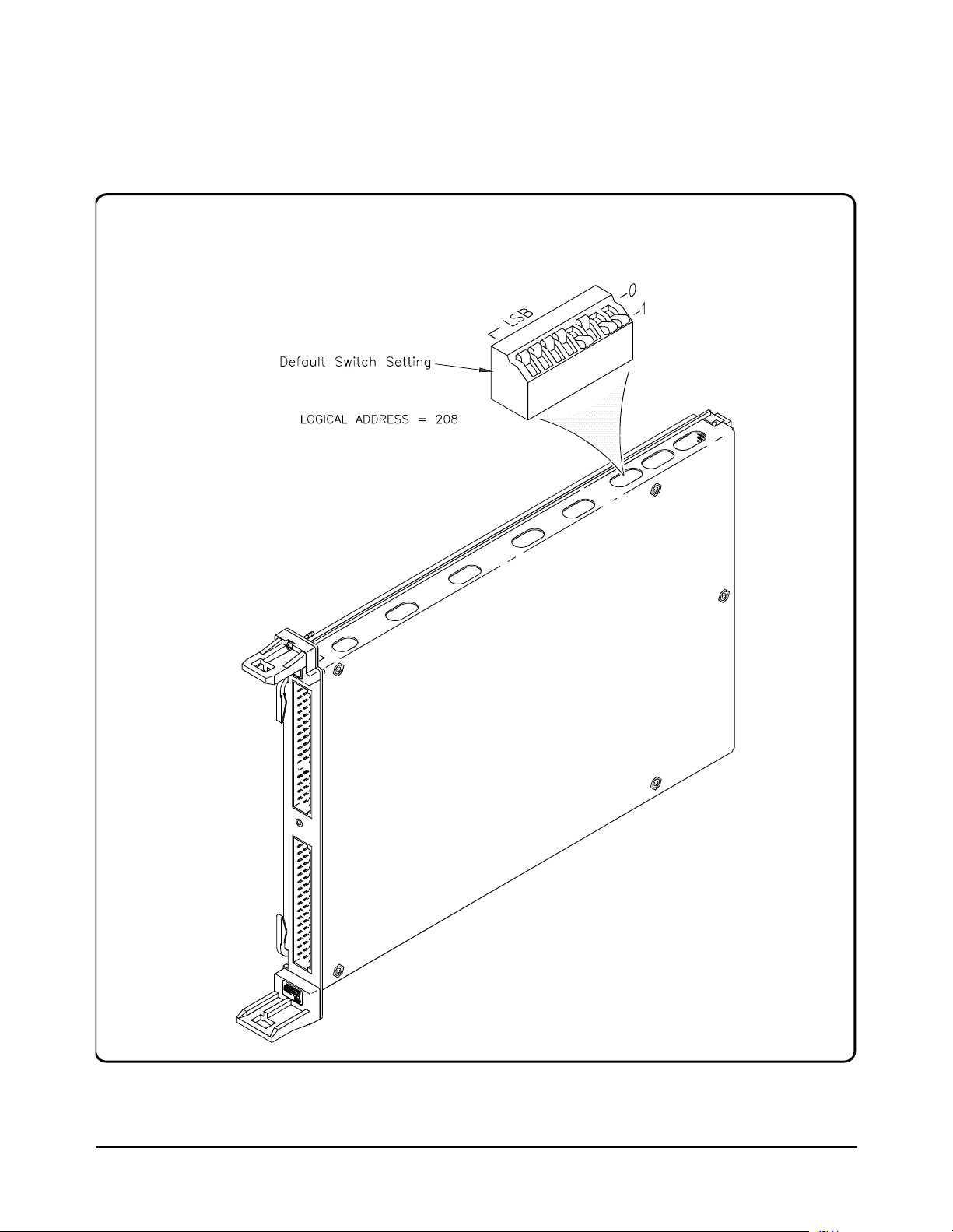
Setting the Logical
Address Switch
Follow the next figure and ignore any switch numbering printed on the
Logical Address switch. W hen installing more than one HP E1422 in a
single VXIbus Mainframe, set each instrument to a different Logical
Address.
Setting the Logical Address Switch
22 Getting Started Chapter 1
Installing Signal
Conditioning
The following illustrations show the steps you’ll use to install Signal
Conditioning Modules. Before you install your SCPs, you should read the
"Separating Digital and Analog SCP Signals" in Appendix D page 421.
Plug-ons
Caution Use approved Static Discharge Safe handling procedures
anytime you have the covers removed from the HP E1422 or are
handling SCPs.
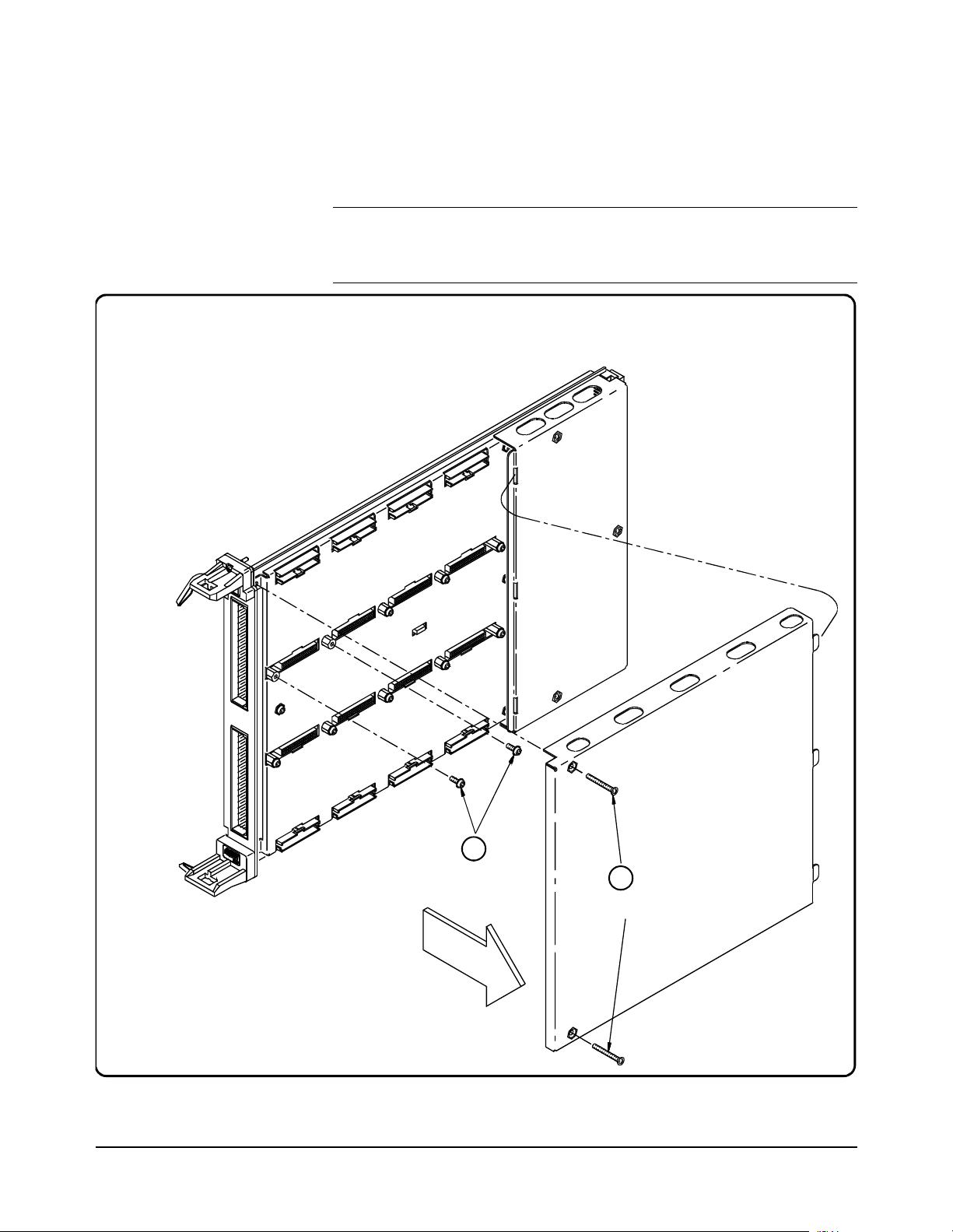
Installing SCPs: Step 1, Removing the Cover HP E1422
2
Remove the SCP
Retaining Screws
1
Remove 2 screws ( #10 Torx);
lift front and sli de out tabs
E1520 REMVLEFT
Getting Started 23Chapter 1
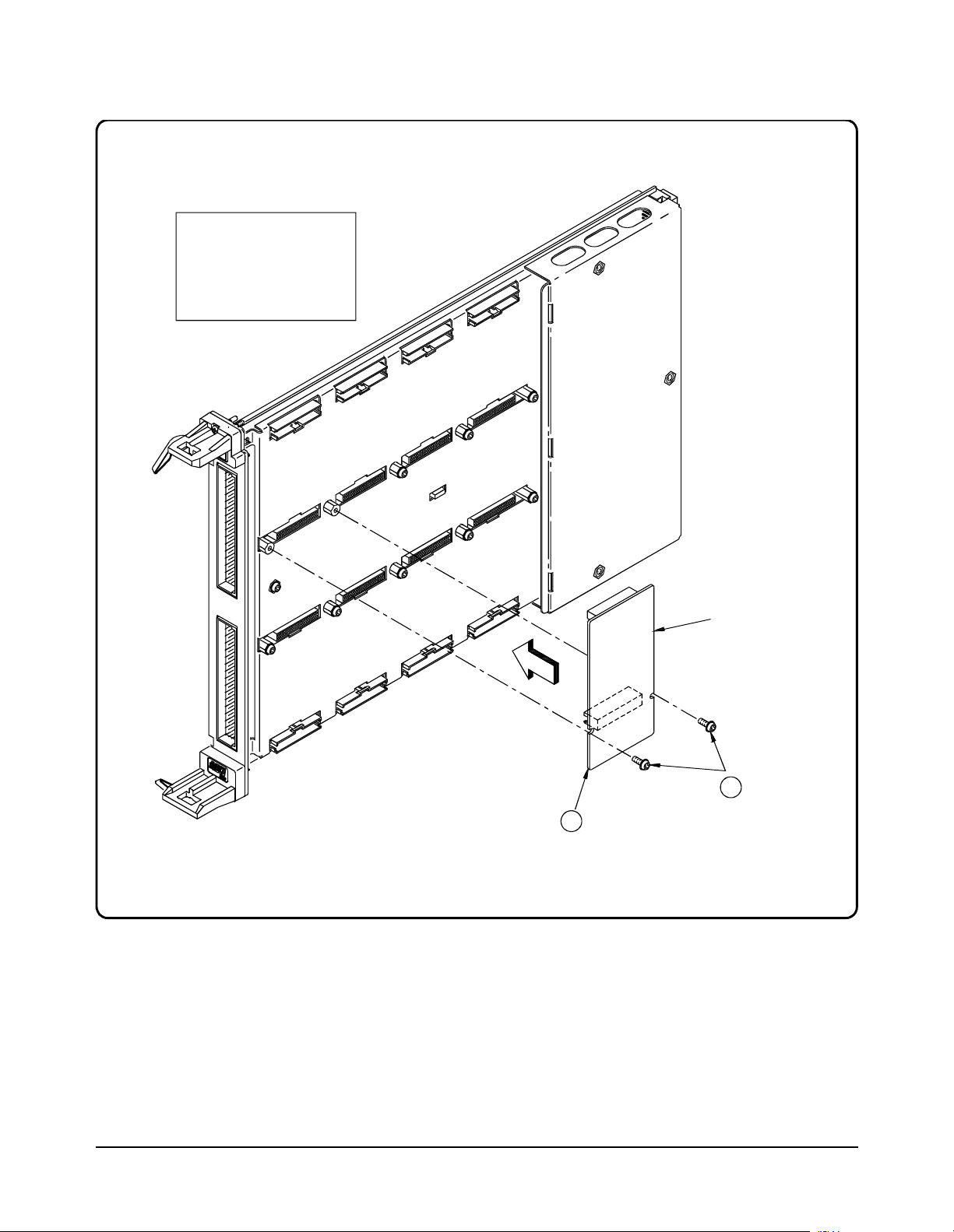
Installing SCPs: Step 2, Mounting an SCP
CAUTION
Use approved Static
Discharge handling
procedures when handling
the HP E1413 Scanning
A/D Module and the SCP s.
E1520 INSLSCP
1
Align the SCP
Connectors with the
Module Connec to rs
and then Push in
SCP
2
Tighten the SCP
Retaining Screws
24 Getting Started Chapter 1
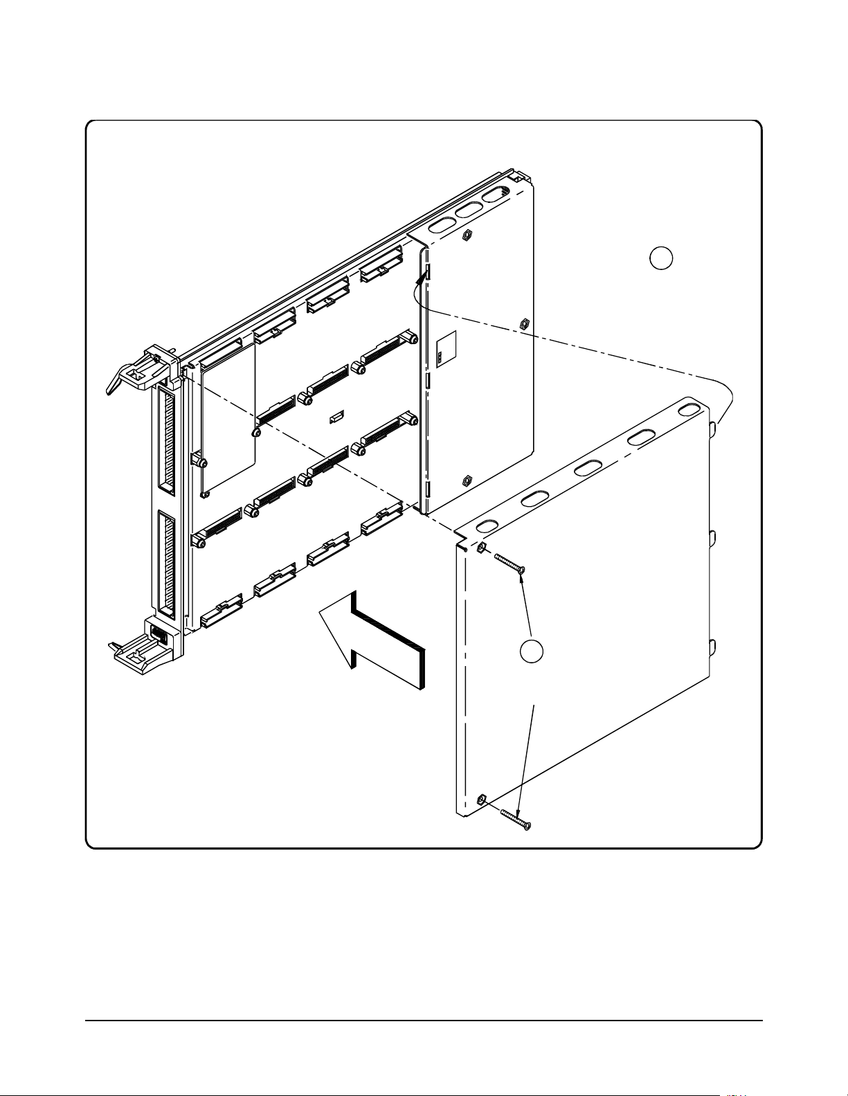
Installing SCPs: Step 3, Reinstalling the Cover HP E1422
1
Line up the 3 Tabs
with the 3 Slots;
then lower cov er
onto the Modul e
E1520 INSTLEFT
2
Tighten
2Screws
Getting Started 25Chapter 1
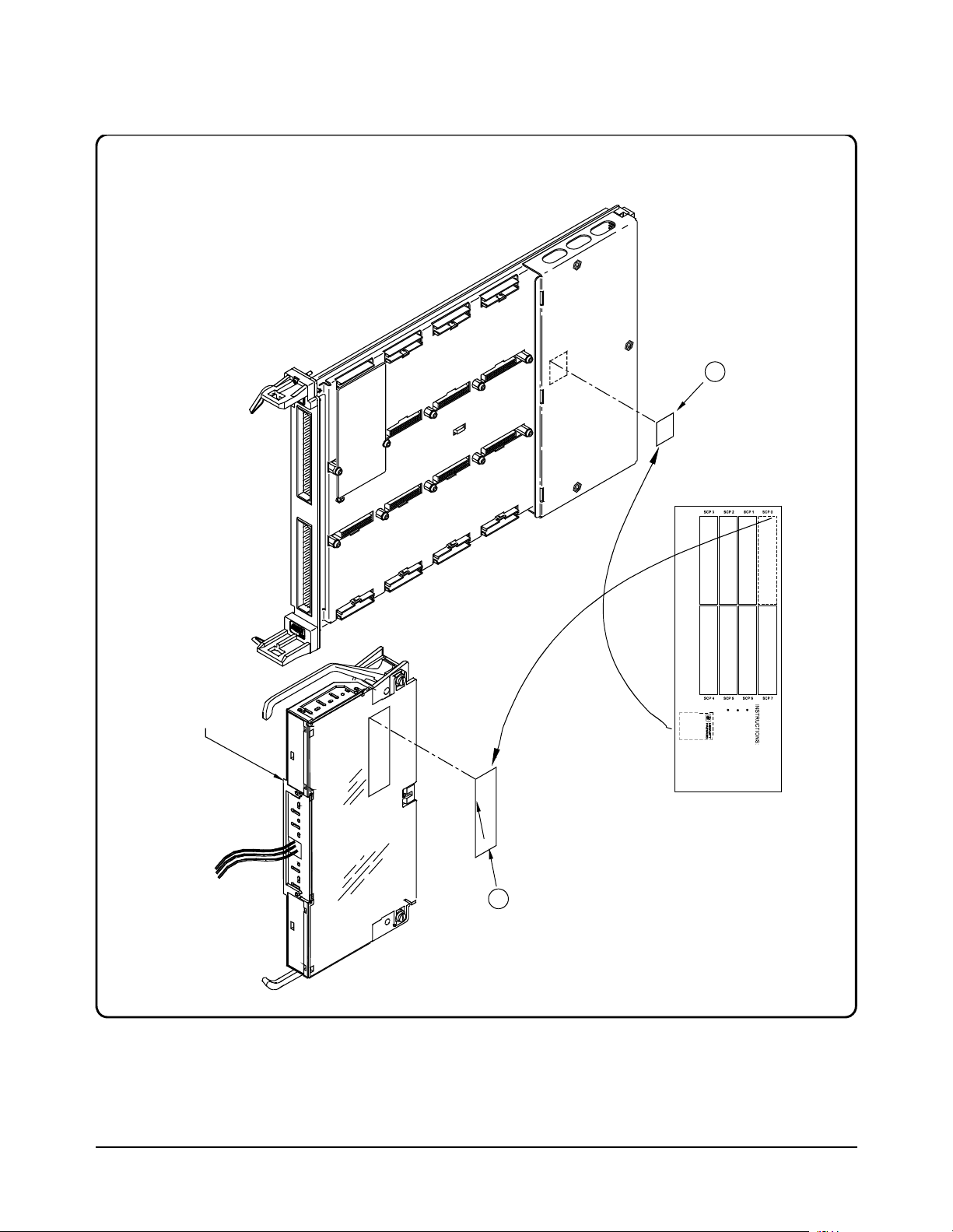
Installing SCPs: Step 4, Labeling
Peel off c orrec t
Label from Card and
Stick on the
appropriate place on
the Co ver
1
Term in al Module
(Connect to A/D
Module L ater)
Stick-onLabel furnished with the SCP
(HP part number: E15xx-84304)
2
Peel off Lab el from
Card and Stick on
the Terminal
Module to be
Connected to the
A/D Module
26 Getting Started Chapter 1

Disabling the
Input Protect
Feature
(optional)
Disabling the Input Protect feature voids the HP E1422’s warranty. The Input
Protect feature allows the HP E1422 to open all channel input relays if any input’s
voltage exceeds ±19 volts (±6 volts for digital I/O SCPs). This fe ature will help to
protect the card’s Signal Conditioning Plug-ons, input multiplexer, ranging
amplifier, and A/D from destructive voltage le vels. The le vel that trips the
protection function has been set to provide a high probability of protection. The
voltage level that is certain to cause damage is somewhat higher. If in your
application the importance of completing a measurement run outweighs the
added risk of damage to your HP E1422, you may choose to disable the Input
Protect feature.
Voids Waranty! Disabling the Input Protection Feature voids the HP E1422’s warranty.
To disable the Input Prote ction feature, locat e and cut JM2202. Make a singl e cut in
the jumper and bend the adjace nt ends ap art. Se e foll owing i llust ration for locat ion
of JM2202.
Disabling
Flash Memory
Access
(optional)
The Flash Memory Protect Jumper (JM2201) is shipped in the “PROG” position.
We recommend that you leave the jumper in this position so that all of the
calibration commands can function. Changing the jumper to the protect position
will mean you won't be able to execute:
•The SCPI calibration command CAL:STORE ADC | TARE
•The register-based calibration commands STORECAL, and STORETAR
•Any application that installs firmware-updates or makes any other
modification to Flash Memory through the A24 window.
With the jumper in the “PROG” po sition, you ca n completely ca librate one or mor e
HP E1422s without removing them from the application system. An HP E1422
calibrated in its working environment will in general be better calibrated than if it
were calibrated separate from its application system.
The multimeter you use dur ing the per i odi c ca li bra ti on c ycl e should be considered
your calibration transfer standard. Have your Calibration Organization control
unauthorized access to its calib ration cons tants. See the HP E1422 Service Manual
for complete information on HP E1422 periodic calibration.
If you must limit access to the HP E1422's calibration constants, you can place
JM2201 in the protected position and cover the shield retaining screws with
calibration stickers. See following illustration for location of JM2201.
Getting Started 27Chapter 1

Accessing and Locating JM2201 and JM2202 HP E1422
Flash MemoryProtect Jumper
Default = PROG
(recommended)
JM2201
E1413 FIG1-3
JM2202
1 Locate
2Cut
3 Bend
Input Protect Jump er
Warning: Cutting this Jumpe r
Voids Your Warranty!
28 Getting Started Chapter 1

Installing the Module
Installation of the HP E1422 VXI module is covered in your HP Mainframe manual.
WARNING All instruments within the VXI mainframe are gr ounded thro ugh
the mainframe chassis. During insta llation, tighten the
instrument’ s retaining screws to secure the instrument to
the mainframe and to make the ground connection.
WARNING SHOCK HAZARD. Only qualified, service-trained personnel who
are aware of the hazards involved should install, configure, or
remove the VXI Module. Disconnect all power sources from the
mainframe, the Terminal Modules, and installed modules before
installing or removing a module.
Instrument Drivers
Two driver types are supplied on the HP Universal Drivers CD that comes with your
Instrument. There is a VXIpl ug&pl ay driver which includes a front panel program
and help file. In addition there is also a down-loadable driver for the HP E1406A
Command Module. Follow the instructions that are presented by the CD setup
program. Also view the readme .txt file pro vided wit h the VXIplug&pl ay driver for
possible update information.
About Example Programs
Examples on CD All example programs mentioned by file name in this manual are available on the
HP Universal Drivers CD supplied with your HP E1422. Again see the readme.txt
file for the specific file locations of these examples.
Example
Command
Sequences
Typical Example
program
Where programming concept s ar e discussed in this manual, the commands to send
to the HP E1422 are shown in the form of command sequences. These are not
example programs because t hey are not written in a ny computer language. Th ey are
meant to show the HP E1422 SCPI commands in th e sequ ence the y shoul d be se nt.
Where necessary th ese sequences include comments to describ e program flow and
control such as loop - end loop, and if - end if. See “Example SCPI Command
Sequence” on page 134. for an example. For VXIplug&play users, there is an
“Example VXIplug&play Driver Function Sequence” on page 135.
The Verify program (file name ve rif.cpp) is printed below to show a typical
VXIplug&play program for the HP E1422.
Getting Started 29Chapter 1

Verifying a Successful Configuration
An example ’C’ progra m source is s hown on th e fol lowing p ages. T his pr ogram is
included on your HP Universal Drivers CD that comes with your HP E1422A (file
name verif.cpp). The program uses the *IDN? query command to verify the HP
E1422 is operational and r esponding t o commands. The program also has an error
checking function ( check( )). It is important to include an instrument error checking
routine in your programs, particularly your first trial programs so you get instant
feedback while you are learning about the HP E1422. Compile this program
according to the plug&play help file (hpe1422.hlp) topics "Introduction to
Programming"
Environments".
/*******************************************************************************
verif.cpp
This example program verifies your instrument installation by reading the
instrument IDs and then querying for and printing the SCP types found.
Use the "Copy Button" in the Help File’s "Example" window to place this code
into the clipboard, then paste this code text into your development tool’s
editor window. Similarly, "Copy" the actual example code from the help file’s
"Example" window and paste it into the location provided below.
This program should be compiled in the ’large’ memory model.
→"Compiling and Linking Programs Using Integrated
link with the hpe1422_32.lib - library file
*******************************************************************************
*/
#include <stdio.h>
#include <stdlib.h>
#include <string.h>
#include <hpe1422.h> /* include the driver header file */
/* GPIB-VXI addressing (0 is the interface number, 208 is the */
/* instrument logical address, INSTR is a VISA resource type) */
#define INSTR_ADDRESS "GPIB-VXI0::208::INSTR"
ViSession addr;
ViStatus errStatus;
/* Function Prototypes */
void main (void); /* Main function */
void rst_inst(void); /* Resets the instrument and sends a device clear */
void reads_instrument_id(void); /* reads instrument software revision */
void check (ViSession addr, ViStatus errStatus); /* checks module errors */
/*******************************************************************************/
void main (void) /* Main function */
{
ViChar err_message[256];
/* Set the session and status variables */
#if defined(__BORLANDC__) && !defined(__WIN32__)
_InitEasyWin();
#endif
30 Getting Started Chapter 1
 Loading...