


CONTENTS
Copyright/Trademark/Documentation Information..................................................... 3
Safety Symbols/WARNINGS ..................................................................................... 4
Reader Comment Sheet ..............................................................................................5
Chapter 1 - Getting Started ............................................................................................ 7
What’s in This Guide?................................................................................................ 7
Steps to Get Started ................................................................................................. 7
If You Need Help ........................................................................................................ 9
Chapter 2 - Installing External PC VXI Systems ........................................................ 11
Using This Chapter................................................................................................ 11
What’s in This Chapter? .................................................................................... 11
What are External PC VXI Systems? ................................................................ 11
Steps to Install External PC VXI Systems .......................................................... 12
Step 1: Identify Your System ................................................................................ 13
Step 1 Overview ................................................................................................ 13
1-1: Inventory/Gather Equipment ...................................................................... 13
1-2: Identify System Hardware .......................................................................... 14
Step 2: Configure Your PC......................................................................................17
Step 2 Overview ................................................................................................ 17
2-1: Install Application Programs....................................................................... 17
2-2: Install PC I_O Cards................................................................................... 18
2-3: Connect Peripherals to PC......................................................................... 18
2-4: Connect PC to Network.............................................................................. 18
Step 3: Install VXI Hardware.................................................................................. 19
Step 3 Overview................................................................................................. 19
3-1: Install Mainframe(s)................................................................................... 20
3-2: Install Slot 0 Card....................................................................................... 21
3-3: Install VXI Instruments ............................................................................... 22
3-4: Connect Interface Cable............................................................................ 26
3-5: Interconnect Mainframes (Optional)........................................................... 27
Step 4: Install Libraries/Drivers............................................................................ 28
Step 4 Overview ................................................................................................ 28
4-1: Install HP I_O Libraries .............................................................................. 28
4-2: Install VXI
4-3: Download SCPI Drivers (HP-IB Only) ........................................................ 32
Step 5: Verify Instrument Communication .......................................................... 34
Step 5 Overview ................................................................................................ 34
5-1: Use Soft Front Panels ................................................................................ 35
5-2: Use VISA Assistant .................................................................................... 37
5-3: Use HP VEE Instrument Manager.............................................................. 39
5-4: Use Resource Manager ............................................................................. 41
plug&play
Drivers....................................................................... 30
Contents 1

Step 6: Program Your System .............................................................................. 43
Step 6 Overview ................................................................................................ 43
6-1: Design Product Connections...................................................................... 43
6-2: Create Product Tests ................................................................................. 45
6-3: Create Test Programs................................................................................ 45
6-4: Make Product Connections ........................................................................ 49
6-5: Test Your Product ...................................................................................... 49
Chapter 3 - Installing Embedded PC VXI Systems.................................................... 51
Using This Chapter................................................................................................ 51
What’s in This Chapter? .................................................................................... 51
What is an Embedded PC VXI System? ........................................................... 51
Steps to Install Embedded PC VXI Systems..................................................... 52
Step 1: Identify Your System ................................................................................ 53
Step 1 Overview ................................................................................................ 53
1-1: Inventory/Gather Equipment ...................................................................... 53
1-2: Identify System Hardware .......................................................................... 54
Step 2: Install VXI Hardware.................................................................................. 56
Step 2 Overview ................................................................................................ 56
2-1: Install Mainframe(s)................................................................................... 56
2-2: Install PC in Mainframe.............................................................................. 57
2-3: Install VXI Instruments ............................................................................... 59
2-4: Interconnect Mainframes (MXIbus) ............................................................ 63
Step 3: Configure Your PC.................................................................................... 64
Step 3 Overview ................................................................................................ 64
3-1: Install Application Programs....................................................................... 64
3-2: Connect Peripherals/Network to PC........................................................... 64
Step 4: Install Libraries/Drivers............................................................................ 65
Step 4 Overview ................................................................................................ 65
4-1: Install HP I_O Libraries .............................................................................. 65
4-2: Install VXI
Step 5: Verify Instrument Communication .......................................................... 70
Step 5 Overview ................................................................................................ 70
5-1: Use Soft Front Panels ................................................................................ 70
5-2: Use VISA Assistant .................................................................................... 73
5-3: Use HP VEE Instrument Manager.............................................................. 75
Step 6: Program Your System .............................................................................. 78
Step 6 Overview ................................................................................................ 78
6-1: Design Product Connections...................................................................... 79
6-2: Create Product Tests ................................................................................. 80
6-3: Create Test Programs................................................................................ 80
6-4: Make Product Connections ........................................................................ 84
6-5: Test Your Product ...................................................................................... 84
plug&play
Drivers....................................................................... 67
2 Contents

Notice
The information contained in this document is subject to change without notice. Hewlett-Packard Company
(HP) shall not be liable for any errors contained in this document. HP makes no warranties of any kind i n regard
to this document, whether express or implied. HP specifically disclaims the implied warranties of
merchantability and fitness for a particular purpose. HP shall not be liable for any direct, indirect, special,
incidental, or consequential damages, whether based on contract, tort, or any other legal theory, in connection
with the furnishing of this document or the information in this document.
Copyright Information
Copyright © 1998 Hewlett -Packard Company. All Ri ghts Reser ved. This document contains inf ormation which
is protected by copyright . All ri ght s ar e res er ved. Repr oduction, adaptation, or tr ans la ti on wit hout pri or wri tt en
permission is prohibited, except as allowed under copyright laws.
U.S. Government Restricted Rights
The Software and Documentation have been developed entirely at private expense. They are delivered and
licensed as "commercial computer software" as defined in DFARS 252.227- 7013 (Oct 1988), DFARS
252.211-7015 (May 1991) or DFARS 252.227-7014 (Jun 1995), as a "commercial item" as defined in FAR
2.101(a), or as "Restricte d computer software" as defined in FAR 52.227-19 (J un 1987)(or any equivalent agency
regulation or contract clause), whichever is applicable. You have only those rights provided for such Software
and Documentation by the applicable FAR or DFARS clause or the HP standard software agreement for the
product involved.
Trademark Information
Microsoft®, Windows®, and Windows NT® are U.S. registered trademarks of the Microsoft Corporation.
All other brand and product names are trademarks or registered trademarks of their respective companies.
Documentation History
All Editions and Updates of th is manual and thei r creat ion dat e are li sted be low. The first Editi on of the manua l
is Edition 1. The Edition number increments by 1 whenever the manual is revised. Updates, which are issued
between Editions, contain replacement pages to correct or add additional information to the current Edition of
the manual. Whenever a new Edition is create d, it will conta in all of the Update information for the previous
Edition. Each new Edition or Update also includes a revised copy of this documentation history page.
Edition 1 .......................................................... December 1998
3
Safety Symbols
Instruction manual symbol affixed to product. Indicates that the user must
refer to the manual for specific WARNING or CAUTION information to
avoid personal in jury or damage to the product.
Indicates the field wiring terminal that must be connected to earth ground before
operating the equipment — prot ects against electrical shock in case of fault.
or
Frame or chassis ground terminal—typically connects to the equipment's
metal frame
Alternating current (AC). Direct Current (DC).
Indicates hazardous voltages.
WARNING Calls attention to a procedure, practice, or condition that could cause bodily
injury or death.
CAUTION Calls attention to a procedure, practice, or condition that coul d possibly cause
damage to equipment or permanent loss of data.
WARNINGS
The following general safety precautions must be observed during all phases of operation,
service, and repair of this produc t. Failure to comply with these precautions o r with sp ecific
warnings elsewhere in this manual violates safety standards of design, manufacture, and
intended use of the product. Hewlett-Packard Company assumes no liability for the
customer's failure to comply with these requirements.
Ground the equipment: For Safety Class 1 equipment (equipment having a protective earth
terminal), an uninterruptible safety earth ground must be provided from the mains power
source to the product input wiring terminals or supplied power cable.
DO NOT operate the product in an explosive atmosphere or in the presence of
flammable gases or fumes.
For continued protection against fire, replace the line fuse(s) only with fuse(s) of the same
voltage and current rating and type. DO NOT use repaired fuses or short-circuited fuse
holders.
Keep away from live circuits: Operating personnel must not remove equip ment covers or
shields. Procedures involv ing th e remo val o f c ove rs or shie ld s are f or u se by servic e- train ed
personnel only. Under certain conditions, dangerous voltages may exist even with the
equipment switched off. To avoid dangerous electrical shock, DO NOT perform procedures
involving cover or shield removal unless you are qualifie d to do so.
DO NOT operate damaged equipment: Whenever it is possible that the safety protection
features built into this prod uct have been impaired, eithe r through physical damage, excessive
moisture, or any other reason, R EMOVE POWER and do not use the product until safe
operation can be verified by service-trained personnel. If necessary, return the product to a
Hewlett-Packard Sales and Service Office for service and repair to ensure that safety features
are maintained.
DO NOT service or adjust alone: Do not attempt internal service or adjustment unless
another person, c apable of rendering fir s t aid and resuscitati on, is present.
DO NOT substitute parts or modify equipment: Because of the danger of introducing
additional hazards, do not install substitute parts or perform any unauthorized modification
to the product. Return the product to a Hewlett-Packard Sales and Service Office for service
and repair to ensure that safety features are maintained.
4

Please fold and ta pe for mailing
Reader Comment Sheet
Getting Started With VXI Guide
Edition 1
You can help us impro ve our manuals by sharing you r comments and suggestions . In appreciation of your time, we will
enter you in a quarterly drawing for a Hewlett-Packard Palmtop Personal Computer (U.S. government employees
are not eligible for the drawing).
Your Name
Company Name
Job Title
Address
City, State/Province
Country
Zip/Postal Code
Telephone Number with Area Code
Please list the system controller, operating system, programming language, and plug-in modules you are using.
fold here
BUSINESS REPLY MAIL
FIRST CLASS PERMIT NO. 37 LOVELAND, CO
POSTAGE WILL BE PAID BY ADDRESSEE
cut along this li ne
HEWLETT-PACKARD COMPANY
Measurement Systems Division
Learning Products Department
P.O. Box 301
Loveland, CO 80539-9984
NO POSTAGE
NECESSARY
IF MAILED
IN THE
UNITED STATES
fold here
Please pencil-in one circle for each statement below: Disagree Agree
• The documentation is well organized. OOOOO
•Instructions are easy to understand. OOOOO
The documentation is clearly written. OOOOO
•
Examples are clear and useful. OOOOO
•
•Illustrations are clear and helpful. OOOOO
The documentation meets my overall expectations. OOOOO
•
Please write any comments or suggestions below–be specific.


What’s in This Guide?
This Getting Started wi th VXI Gui de is de si gned to guide you through a set
of steps to identify, install, configure, and program your PC-based VXI
system. This guide does not provide detailed information in each step.
Rather, the guide suggests documentation and/or tools you can use to do
the step.
The information in this guide is grouped according to the type of PC
(External or Embedded) for major VXI system types . Chap ter 2: In st alling
External PC VXI Systems shows steps to install external PC VXI systems.
Chapter 3: Installing Embedded PC VXI Systems shows steps to install
embedded PC VXI syst ems.
Note This guide does not show how to install Fibre Channel, GPIO, RS-232
or HP-UX VXI systems, nor does it attempt to include all combinations of
PC-based VXI systems. See th e documentatio n shipped with t he equipment
for specific steps to install these systems.
Chapter 1
Getting Started
Note If you purchased an integrated (pre-configured) VXI system, some of the
steps in this guide (such as installing VXI instruments, etc.) may already
have been completed. In this case, skip the applicable step and go to the
next step in the guide.
Steps to Get Started
Get Acquainted with VXI
If you are not familiar with VXI systems, terms and concepts you
may want to read the Feeling Comfortable with VXI booklet. If you
are familiar with VXI terms, you can skip to the next step.
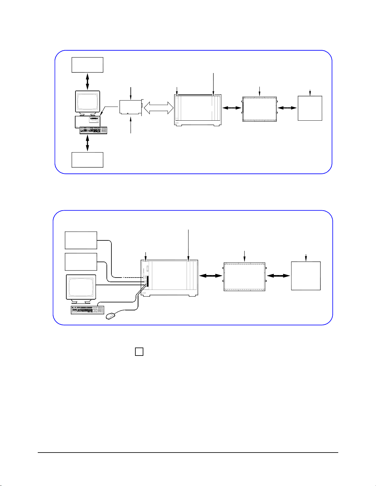
Determine Your VXI System Type
In this guide, installation steps are divided according to the PC for
your system: External PC or Embedded PC. To determine your system
type, see Figure 1 (External PC) or Figure 2 (Embedded PC).
Getting Started 7
Peripherals
Network
Peripherals
VXI Instruments Installed
in Slots 1 through n
PC I_O Card (Optional)
Installed in PC
PC I_O
Card
External
PC
Typically, HP-IB
or
IEEE-1394
VXI Slot 0 Controller
Installed in Slot 0
Interface
Mass Interconnects
VXI Mainframe
Figure 1. Typical External PC VXI System
VXI Instruments Installed
in Slots 2 through n
Embedded PC
(HP E6234A, etc.)
Installed in Slots 0 and 1
(Optional)
Mass Interconnects
Inter-
Connects
Typically,
Unit
Under
Test
(UUT)
Your
Product
Typically
Unit
Under
Test
(UUT)
Network
VXI
Mainframe
Inter-
Connects
Figure 2. Typical Embedded PC VXI System
Begin the Installation Process
For an External PC system, go to Chapter 2: Installing External PC
VXI Systems. For an Embedded PC syst em, go t o Chapter 3: Installing
Embedded PC VXI Systems. For either system, see the Getting Started
with VXI poster for a ge neral se quence of steps t o use. Fo llow the steps
listed in the applicable chapter of this guide to install your system.
Your
Product
8 Getting Started

If You Need Help If You Have Questions
If you have any questions or require technical support from HewlettPackard, you can contact us by telephone or via the World-Wide Web
at the numbers/addresses shown. When you call or write us, please
provide the following information:
1 Your VXI system hardware configuration
2 Your PC operating system (NT, etc.) and PC version
3 The programming environment you are using
4 A complete description of the problem
5 A list of steps necessary to recreate the problem
Telephone Numbers
Americas HP Call Center: 1-800-452-4844
European HP Call Center: +31-20-547-9900
Japan HP Call Center: +81-426-56-7832
World-Wide Web
http://www.tmo.hp.com/tmo/contacts/English/callcenters.html
Reader Comment Sheet
If you have any comments on this guide, please fill out and return the
Reader Comment Sheet in this guide.
Getting Started 9

10 Getting Started

Installing External PC VXI Systems
Using This Chapter
Chapter 2
What’s in This Chapter?
This chapter shows a suggested six-step process to install, configure,
and program an external PC VXI system. The chapter contents are:
• Step 1: Identify Your System . . . . . . . . . . . . . . . . . . .page 13
• Step 2: Configure Your PC. . . . . . . . . . . . . . . . . . . . .page 15
• Step 3: Install VXI Hardware. . . . . . . . . . . . . . . . . . .page 19
• Step 4: Install Libraries/Drivers . . . . . . . . . . . . . . . . .page 28
• Step 5: Verify Instrument Communication. . . . . . . . .page 34
• Step 6: Program Your System. . . . . . . . . . . . . . . . . . .page 43
What are External PC VXI Systems?
Peripherals
Network
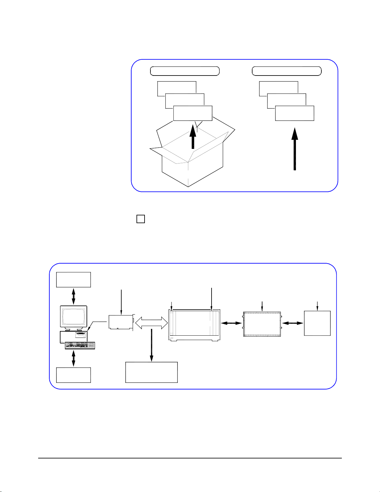
In this guide, external PC VXI systems are d efined to consist of an
external Windows-based PC and an interface between the PC and a
VXI mainframe, with connections between your product (typically
a Unit Under Test (UUT)) and VXI instruments. See Figure 1 for a
typical external PC VXI system.
VXI Instruments Installed
in Slots 1 through n
PC I_O Card (Optional)
Installed in PC
PC I_O
Card
External
PC
Typically, HP-IB
or
IEEE-1394
VXI Slot 0 Controller
Installed in S lot 0
Interface
VXI Mainframe
Mass Interconnects
Inter-
Connects
Typically,
Unit
Under
Test
(UUT)
Your
Product
Figure 1. Typical External PC VXI System
Installing External PC VXI Systems 11
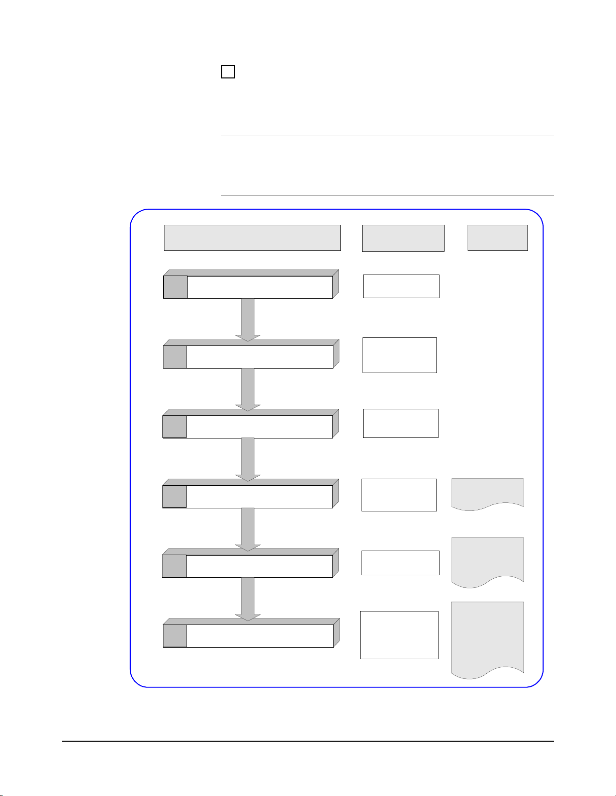
Steps to Install External PC VXI Systems
Figure 2 shows suggested steps to install, configure, and program an
external P C VXI system.
Note Since your VXI system may vary from that shown in Figure 1 you may
need to modify the steps in this guide. If you received a pre-configured
system, skip any steps that have already been accomplished such as VXI
instruments already installed in the mainframe, etc.
To do this step: And this
Identify Your System
1
2
3
4
Configure Your PC
Install VXI Hardware
Install Libraries/Drivers
You can use this
documentation:
Connection Diagram
Packing List
PC Manuals
Peripheral s Manuals
Network Manuals
Connection Diagrams
Configuration Guides
Hardware Manuals
Instrument Manuals
HP VISA Manual
HP SICL Manuals
software:
I_O Libraries CD
Instrument CD
Verify Instrument Communication
5
Program Your System
6
Figure 2. Steps to Install External PC VXI Systems
12 Installing External PC VXI Systems
PC Manuals
VXI Instrument Guides
Interconnect Manuals
Your Product Manuals
Programming Manuals
Instrument Manuals
PC Manuals
Soft Front Panels
VISA Assistant
HP VEE Instr Mgr
Resource Mgr
Visual C/C++
Visual Basic
HP VEE
HP BASIC
HP VISA
HP SICL
Other Applic ations
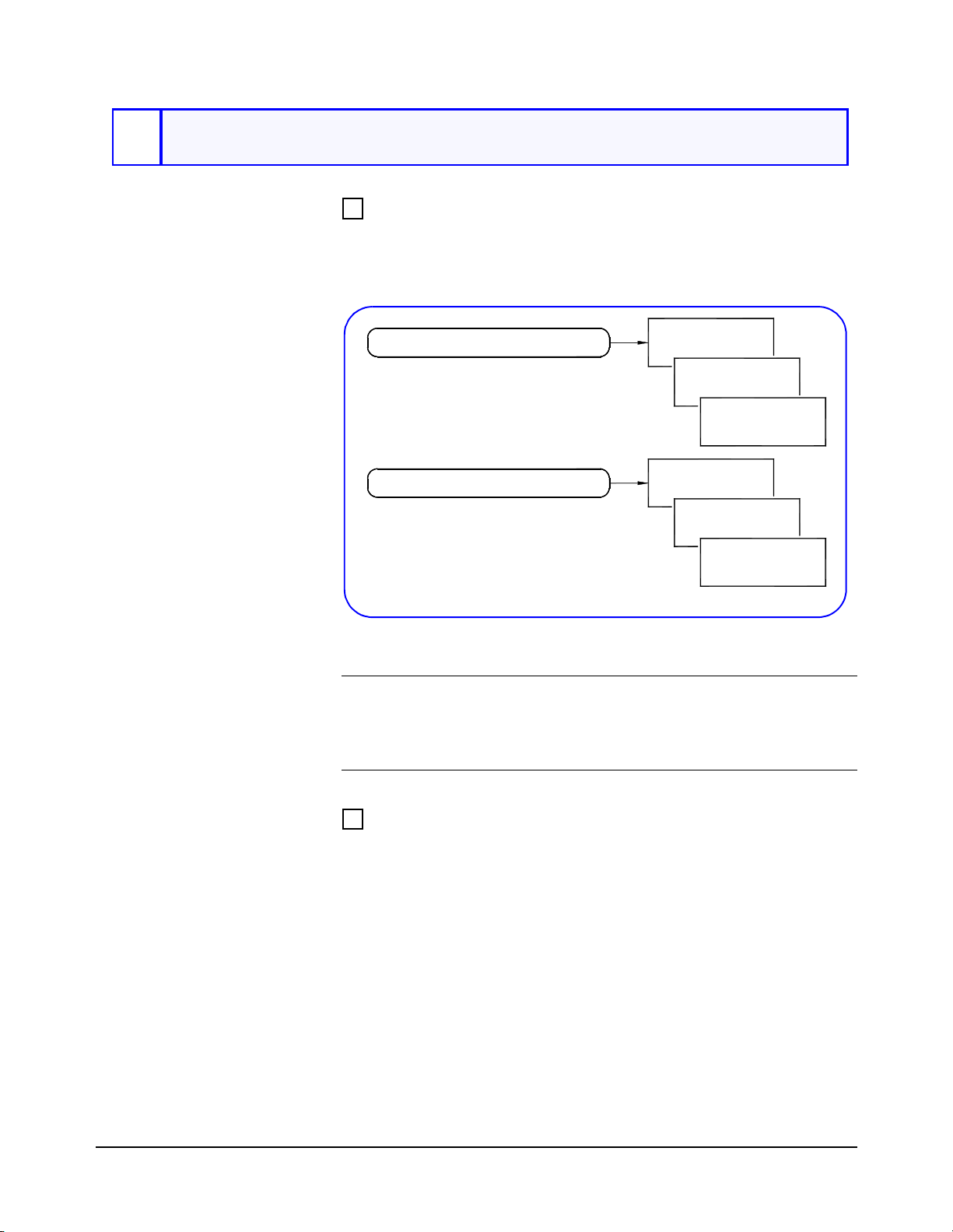
1
Identify Your System
Step 1 Overview What’s in This Step?
The first step i n in stall ing y our VXI syst em is to unp ack an d inve ntory
the system, and to identify your specific VXI system type. This step
includes the procedures in Figure 3.
1-1. Inventory/Gather Equipment
1-2. Identify System Hardware
Figure 3. Steps to Identify Your VXI System
WARNING During all phases of installation, operation, service or repair
of any equipment for any step in this guide, you must follow
all safety instructions in the applicable manual or guide, as
well as the safety instructions in this guide.
Hardware
Software
Documentation
HP-IB
IEEE-1394
MXIbus
1-1: Inventory/
Gather Equipment
Inventory VXI Equipment/Gather Other Equipment
1 Unpack and inventory hardware, software, and documentation
for your VXI system (see Figure 4). For pre-configured systems,
you can use the Packing List that accompanied this guide to check
the equipment contents.
2 Gather other items not received with your system, such as your
PC and PC I_O cards, computer documentation, tools, etc., that
you may need to assemble your system (see Figure 4).
Installing External PC VXI Systems 13
1-2: Identify
System Hardware
1. Unpack Your VXI Equipment
Equipment
Software
Documentation
VXI System
2. Gather Other Items
Your PC
Tools
Documentation
Other Items
Figure 4. Inventory/Gather Equipment
Identify Your System Type
In this guide, external PC VXI systems are categorized as HP-IB
(Figure 5), IEEE-1394 (Figure 6), or MXIbus (Figure 7). Select the
system type that is closest to your system.
Peripherals
Network
HP-IB Card
(HP 82350A, etc.)
Installe d in P C
External
PC
HP-IB
Interface
Card
(Optional)
HP-IB Rack & Stack
Equipment
Figure 5. Typical HP-IB VXI System
HP E1406/E1306
Installed in Slot 0
HP-IB
VXI Instruments Installed
in Slots 1 through n
VXI M a in fr a m e
(Optional)
Mass Interconnects
Inter-
Connects
Typically,
Unit
Under
Test
(UUT)
Your
Product
14 Installing External PC VXI Systems

Peripherals
Network
Peripherals
IEEE-1394 Card
(AHA-8940, etc.)
Installed in PC
IEEE-1394
External
PC
HP-IB Rack & Stack
HP-IB Card
(HP 82350A, etc.)
Installed in PC
External
PC
HP E1482 installed in slot 1
VXI Instruments Installed
in Slots 1 through n
(Both Mainframes)
HP E8491A
Installed in Slot 0
IEEE-1394
Interface
Card
(Optional)
Equipment
VXI
Mainframe
#1
VXI
Mainframe
#2
Figure 6. Typical IEEE-1394 VXI System
VXI Instruments Installed
in remaining slo ts
(Both Mainframes)
HP E1406 in slot 0
HP-IB
HP-IB
Interface
Card
VXI
Mainframe
#1
(Optional)
Mass Interconnects
Inter-
Connects
(Optional)
Mass Interconnects
Inter-
Connects
Typically,
Unit
Under
Test
(UUT)
Your
Product
Typically,
Unit
Under
Test
(UUT)
Your
Product
Network
VXI
Mainframe
#2
Figure 7. Typical MXIbus VXI System
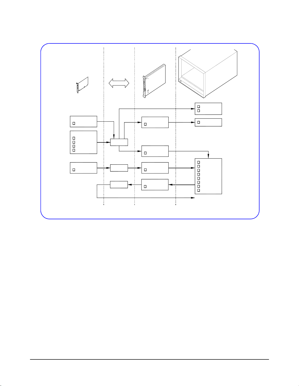
Identify Hardware
Use Figure 8 to identify the hardware for your VXI system, including
PC I_O cards, mainframe(s), slot 0 card, and VXI instruments. You
may want to copy this figure and highlight the specific hardware in
your system for use in future steps.
Installing External PC VXI Systems 15
PC I_ O
Cards
LAN/HP-IB
E205 0 A
HP-IB
82335B
82341C
82341D
82350A
IEEE -1 3 94
PCI C a rd
Inter fa ce s
HP-IB
IEEE-1394*
MXIbus*
VXI
Controllers
HP-IB Cmd
E130 6 A
HP-IB Cmd
E140 6 A
IEEE-1394
E849 1 A
VXIb u s Ext
E148 2 B
Mainframes
E130 0 B
E130 1 B
E130 2 A
E140 1 B
E142 1 B
E840 1 A
E840 2 A
E840 3 A
E840 4 A
E840 8 A
Othe r
To Next
Mainframe
* IEEE-1394 (HP E8491A) and M X Ibus (HP E14 82B) systems allow for multiple mainframes.
Figure 8. Typical External PC VXI Hardware
16 Installing External PC VXI Systems
2
Configure Your PC
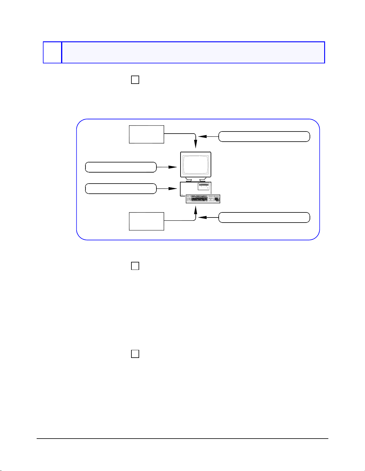
Step 2 Overview What’s in This Step?
This step gives guidelines to configure an external PC for use with
a VXI system. Figure 9 shows the parts of the VXI system that are
installed when this step is completed.
Peripherals
2-1. Install Applications
2-2. Install PC I_O Car d
Network
Figure 9. Steps to Configure Your PC
What You Will Need for This Step:
2-3. Connect Peripherals to PC
External
PC
2-4. Connect PC to Network
• Your PC
• PC I_O Cards
• Peripherals to be connected to PC (printers, plotters, etc.)
• ESD Wrist Strap (supplied with some pre-configured systems)
• Standard Torx (or equivalent) Screwdriver
• PC I_O Card Installation Guide
• PC User’s Manual
• Peripherals Installation Manuals
2-1: Install
Application
Programs
Install Application Programs in Your PC
If you have not already done so, turn the PC ON and install the
application programs to program the VXI system, such as Visual
C/C++®, HP VEE, Vi sual Basic®, etc. Then, turn the PC OFF.
Installing External PC VXI Systems 17
2-2: Install
Install PC I_O Cards in Your PC
PC I_O Cards
Caution To avoid potential damage to your PC, we suggest you wear an
Note Before you can use the PC I_O card with a VXI system, you must configu re
1 Install required PC I_O card(s) into your PC. See the applicable
PC I_O Card Installation Guide for instructions.
ESD wriststrap and observe all ESD precautions when installing (or
removing) PC I_O cards.
2 Turn the PC ON and verify proper operation of the PC.
the interface. We will do this in Step 4-1: Install HP I_O Libraries.
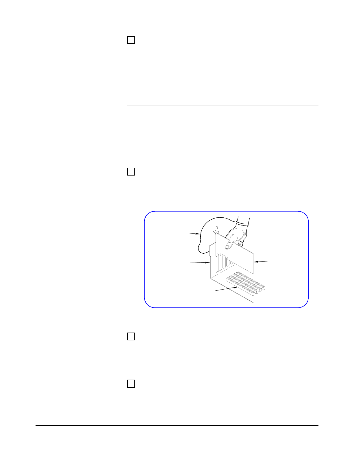
Example: Installing an HP 82350A PC Card
For example, you can use the instructions in the HP 82350 PCI
HP-IB Interface Installation Guide to install an HP 82350A card
into a PCI slot in the PC (see Figure 10).
2-3: Connect
Peripherals to PC
2-4: Connect PC to
Network
ESD
Wrist Strap
External PC
Chassis
PCI Slot
Figure 10. Example: Installing HP 82350A Card
Connect Peripherals to PC (OPTIONAL)
If not already done, connect peripherals (printer, plotter, etc.) to
the PC as required. See the applicable peripherals documentation for
installation instructions .
Connect PC to Your Network (OPTIONAL)
As required, connect the PC to your network. See your System
Administrato r for connection requirements.
HP 82350A
18 Installing External PC VXI Systems

3
Install VXI Hardware
Step 3 Overview What’s in This Step?
This step gives guidelines to install the VXI hardware. Figure 11
shows the parts of this st ep, and shows the hardware installed
after this step is completed. For pre-configured systems, you can
skip the steps that do not apply to your system.
3-1. Install Mainframes in Rack
3-2. Install Slot 0 Card
3-4. Connect Interface Cable
PC
3-3. Install VXI Instruments
3-5. Interconnect Mainframes (Optional)
Figure 11. Steps to Install VXI Hardware
Installing External PC VXI Systems 19
What You Will Need for This Step:
• VXI Mainframe(s)
• Rack Mount Installation Kit (as required)
• VXI Slot 0 Card(s)
• VXI Instrument s to be installed
• Mainframe User’s/Service Manual
• Rack Mount Installation Instructions (as required)
• Slot 0 Controller User’s Manual
• User’s Manuals for each VXI instrument to be installed
3-1: Install
Mainframe(s)
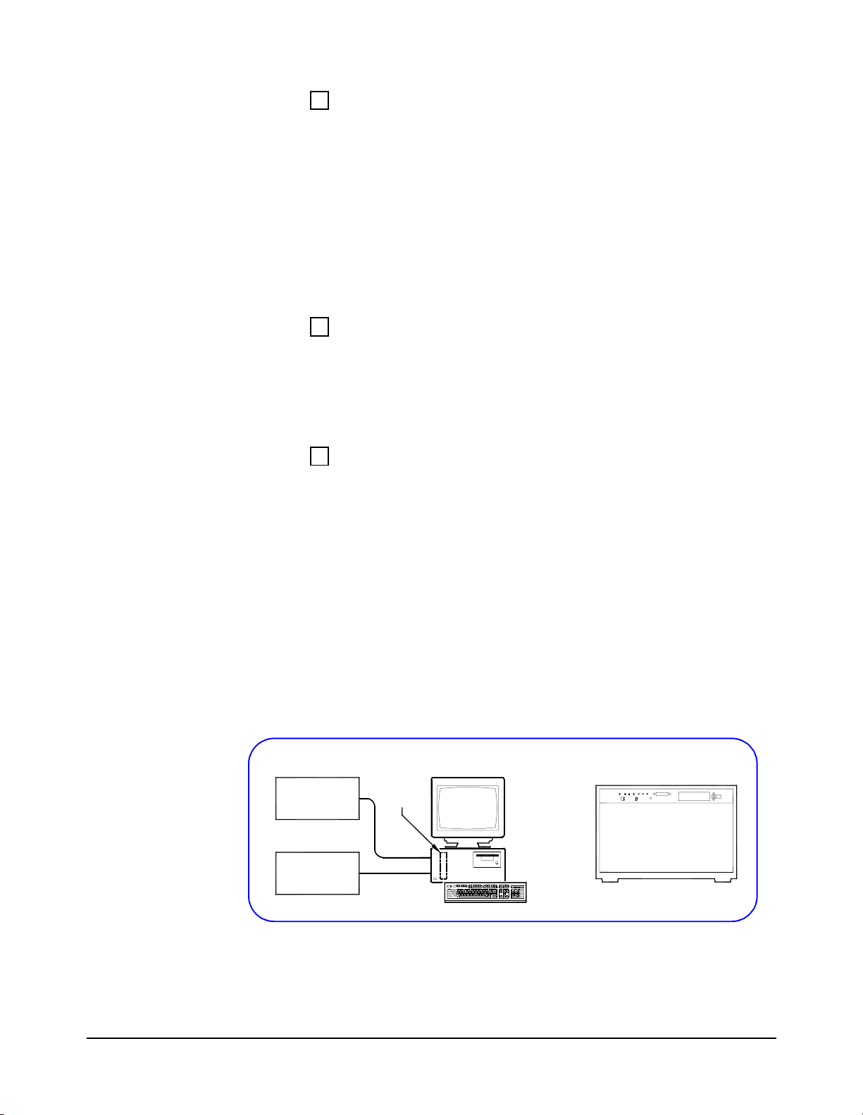
Rack Mount VXI Mainframe(s) (OPTIONAL)
As required, rack mount the mainframe(s) for your VXI system using
the procedures in the applicable Rack Mount Installation Guide. If
rack mounting is not required, go to the next step Configure the
VXI Mainframe(s).
Configure the VXI Mainframe(s)
1 If rack mounting is not required, place the mainframe on a bench or
table as desired.
2 Install the ground conne ctor (for 66 Hz and abo ve operation ONLY),
connect the power cord, and configure each mainframe as required
as shown in the applica ble M ainfr ame User/ Servi ce Man ual. Fi gure
12 shows the hardware installed after this step.
3 Turn mainframe(s) power ON and observe the power-on sequence
(if any) for the mainframe(s). See the applicable Mainframe
User/Service Manual for details.
4 Turn mainframe(s) power OFF.
Peripherals
Network
Figure 12. Installing/Configuring Mainframes
20 Installing External PC VXI Systems
PC I_O
Card
VXI
Mainframe
External
PC
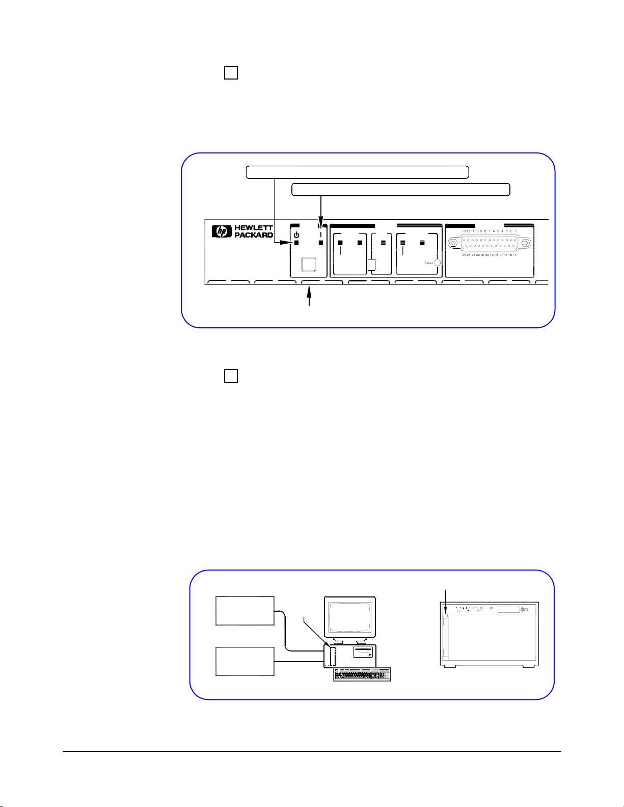
Example: HP E8404A Power-On Sequence
To observe the HP E8404A C-Size mainframe power-on sequence,
plug the power cord into an AC outlet. The amber Standby Indicator
(see Figure 13) should turn ON. Then, press the Power switch. The
Green Light should turn ON, and the Amber Light should turn OFF.
Power Switch OFF: Amber Light ON, Green Light OFF
Power Switch ON: Green Light ON, Amber Light OFF
3-2: Install Slot 0
Card
0 1
Power
System Backplane
Power
Supply
2
Status
Fans
TempOnStdby
Full
Var
3
SYSFAIL
Activity
4 56
Diagnostic
HP E8404A Front Panel
Figure 13. Example: HP E8404A Power-On Sequence
Install Slot 0 Controller Card in Mainframe 1
1 Set the VXI Slot 0 Controller Card switch settings as required
for your system. See the applicabl e Slot 0 Contro ller Use r’s Manual
for details. In general, you will not need to change the Slot 0 card
switches from the default settings.
2 Install the VXI Slot 0 card in VXI Mainframe 1. See the applicable
Slot 0 Controller User’s Manual for installation steps. Figure 14
shows the hardware install ed after this step.
3 Turn mainframe power ON and observe the Slot 0 card front panel
power-on display sequence. Then, turn mainframe power OFF. If
required, correct hardware errors and retest.
HP E1406A, HP E8491A, etc.
PC I_O
Peripherals
Network
Card
VXI
Mainframe
External
PC
Figure 14. Installing Slot 0 Card in Mainframe
Installing External PC VXI Systems 21
3-3: Install VXI
Ways to Install VXI Instruments
Instruments
This step shows two ways to install VXI instruments in mainframes.
The first way is to use the HP VXI Installation Consultant (HP VIC).
The second way is to install using the procedures in this step.
• If you want to use HP VIC, go to “Installation Using HP VIC”.
HP VIC is a utility that provides a structured way to configure
and install VXI instruments, and to check the installation.
• If you do not want to use HP VIC, go to “Installation Without
Using HP VIC”.
Installation Using HP VIC
To use HP VIC:
1 Turn mainframe and PC power OFF. Connect the interface cable
(HP-IB or IEEE-1394) from the Slot 0 card (in the mainframe) to
the PC I_O card (in the PC). Turn PC power ON (leave mainframe
power OFF).
2 Insert the Hewlett-Packard Universal Instrument Drivers CD into
the CD-ROM drive and wait a few seconds for the setup
instructions to appear.
3 If the setup screen does not appear in a few se conds, clic k Start|Run
and then type <drive>: setup.exe in the Run box , where dr ive is your
CD-ROM drive.
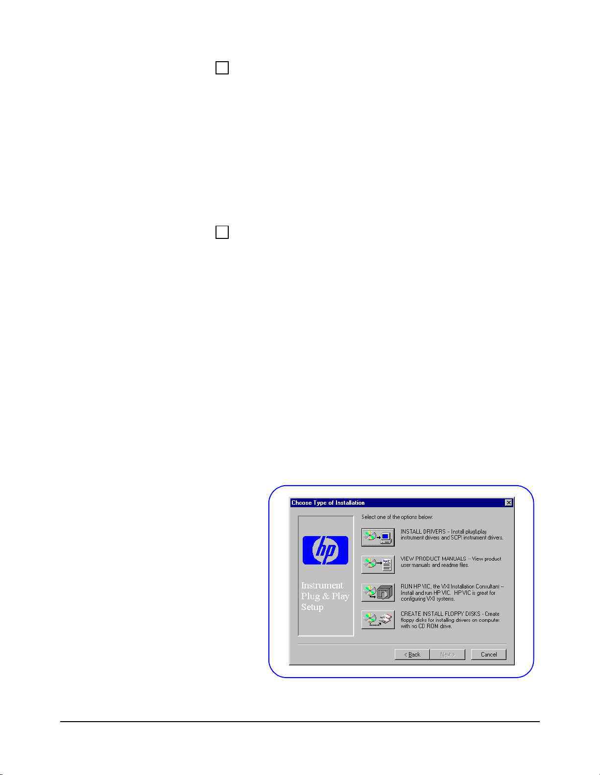
4 When the main menu appears, click Launch Installer or View
Manuals. Click Next on the next screen and Yes on the third screen
to go to the Choose Type of Installation screen (see Figure 15).
22 Installing External PC VXI Systems
Figure 15. Choose Type of Installation Screen

5 From the Choose Type of Installation screen, click the RUN
HP VIC... icon to display the Welcome to HP VIC screen.
6 From this screen, click Ne w--> and follow t he on-screen i nstructions
to install and check your VXI instruments and to (optionally) print
the results.
7 If you have HP-IB Rack & Stack instruments or a termina l to install,
go to St ep 3- 4: Connect Interface Cable . Otherwise, go to Step 3-5:
Interconnect Mainframes.
Installation Without Using HP VIC
1 The first step to install VXI instruments is to select the mainframe
slot to use for each VXI instrument. See the applicable Mainframe
User’s/Service Manual or Instrument User’s Guide for guidelines.
2 When you have selected a slot for an instr ument, enter the instr ument
model number , n ame, a nd serial number for the in st rument in Table
1. (The instrument serial number is located on the side of the
instrument.) Do this for all instruments to be installed.
Note For pre-configured systems, the Installed VXI Instruments List in the
Owner’s Pack lists instrument model number, name, logical address, and
serial number for each installed VXI instrument.
Table 1. VXI Instruments Installed in Mainframe
Slot Model Number Instrument Name Logical Address Serial Number
0
1
2
3
4
5
6
7
8
9
10
11
12
Installing External PC VXI Systems 23

Set VXI Instrument Logical Addresses
1 When you have selected the slot for each VXI instrument, the next
step is to set the i nstrument logical addresse s (LADDR) as re quired.
In general, you can use the factory-set (default) logical addresses.
2 If you need to set other logical addresses, use the following
guidelines. See the applicable Mainframe User’s/Service Manual
or Instrument User’s Guide for details.
• The logical address for each VXI i n st ru ment is set by the Logical
Address (LADDR) switch on the ins trument. The logic al addr ess
value is the sum of the values of the logical address switches set
to the closed position (see Figure 16).
• For HP-IB (HP E1406A Command Module) systems, each VXI
instrument must have a separate logical address and the logical
address must be a multiple of 8 (8, 16, 24, etc.).
• For IEEE-1394 (HP E8941A Interconnect) systems, each VXI
instrument must have a separate logical address but the logical
address does not have to be a multiple of 8.
• A multimeter and one or more multiplexers can be used to form
a scanning multimeter. In this case, the instruments must be in
adjacent mainframe slots and must have sequential logical
addresses (see Figure 17). In addition, for HP E1406A systems
the multimeter must have a logical address that is a multiple of 8.
3 When you have selected the logical address for an instrument, set
the address using the LADDR switch on the instrument. Then,
record the logical address in Table 1. Repeat for each instrument.
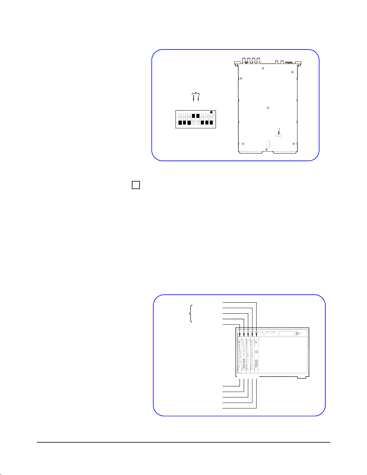
Example: Setting Multimeter Logical Address
Figure 16 shows an HP E1411B multimeter with the Logical Address
switch set to 24. Since switch 3 (logical value = 8) and switch 4
(logical value = 1 6 ) a re b o th closed, the sum of the lo gic al values (24)
is the logical addres s for t he HP E1411B. See the HP E1326B/E1411B
User’s Guide for details.
24 Installing External PC VXI Systems
16+8=24
128
64
32
16
8
4
2
1
1
0
5
7
4
6
Switch Address set to 24
1
0
1
0
2
3
Address
Switch
Location
Figure 16. Example: HP E1411B Logical Address Switch
Example: Scanning Multimeter Logical Addresses
Figure 17 shows an HP E1406A installed in Slot 0 and VXI
instruments installed in slots 1 through 4 of an HP E8404A VXI
mainframe. The HP E1411B multimeter and the two HP E1460A
multiplexers form a scanning multimeter since they are in adjacent
mainframe slots, and they have sequential (24, 25, 26) logical
addresses.
Since this is an HP-IB (HP E1406A) system, the HP E1411B
multimeter must have a logical address that is a multiple of 8 (24 in
this case). For an IEEE-1394 (HP E8491A) system, the three
instruments must still be in adjacent mainframe slots, but could have
any three sequential logical addresses (such as 17, 18, 19).
HP E1441A
Scanning
Multimeter
Figure 17. Example: Scanning Multimeter Logical Addresses
HP E1460A
HP E1460A
HP E1411A
HP E1406A
LADDR
0
24
25
26
80
HP E8404A
VXI Mainframe
210 43
Installing External PC VXI Systems 25

Install VXI Instruments in Mainframe
1 As required, perform Logical Address switch (and other switch)
setting changes for each VXI instrument. See the previous step and
the applicable Instrument User’s Guide for details.
2 Turn mainframe power OFF. Then, install each VXI instrument
in the slot(s) you previously identified. Figure 18 shows the
hardware connected at the end of this step.
3 Turn mainframe power ON and observe each instrument’s power-
on display sequence (if any). See the applicable Instrument User’s
Guide for details. Then, turn mainframe power OFF.
HP E1406A, HP E8491A,
etc. in Slot 0
PC I_O
Peripherals
Network
Card
External
PC
S
L
O
T
1
VXI
Mainframe
VXI Instruments in Slots
h
u
g
o
r
h
t
1
S
L
O
T
n
n
3-4: Connect
Interface Cable
Figure 18. Installing VXI Instruments in the Mainframe
Connect Interface Cable
1 Connect one end of the interface cable to the PC I_O card you
installed (in Step 2). Connect the other end of the cable to the
Slot 0 Controller card. Figure 19 shows the hardware connected
at the end of this step (not including terminals or Rack & Stack
equipment).
HP E1406A, HP E8491A,
etc. in Slot 0
Peripherals
External PC
(Rear View)
Network
Figure 19. Connecting the Interface Cable
Interface Cable
from PC I_O Card
to Slot 0 Card
S
L
O
T
1
VXI
Mainframe
VXI Instruments in Slots
h
u
g
o
r
h
t
1
S
L
O
T
n
n
26 Installing External PC VXI Systems
 Loading...