


Agilent Technologies Infi niiVision
6000 Series Oscilloscopes
Data Sheet
Engineered for the best signal visibility

If you haven’t purchased an Agilent scope lately,
why should you consider one now?
Agilent has been the fastest growing oscilloscope supplier since 1997 (source: Prima
.
Data, 2007)
advanced technology that will allow you to see more subtle signal detail and more
infrequent events than any other scope on the market. See the Infi niiVision 6000
Series oscilloscope—the industry’s best for signal viewing.
Wonder why? Agilent engineers developed the Infi niiVision 6000 Series with
There is no better way to experience
the superiority of the Infi niiVision 6000
Series scopes than to see it.
Contact Agilent today to request an
evaluation.
Or visit:
www.agilent.com/fi nd/mso6000
The Infi niiVision 6000 Series offers bandwidths up to 1 GHz. Each model, equipped with a 6.3” XGA LCD display, comes in
a whisper-quiet package that weighs only 11 pounds.
Model Bandwidth Sample rate Memory Scope channels Digital channels Update rate
DSO6012A
DSO6014A 4
MSO6012A 2
MSO6014A 4
DSO6032A
DSO6034A 4
MSO6032A 2
MSO6034A 4
DSO6052A
DSO6054A 4
MSO6052A 2
MSO6054A 4
DSO6102A
DSO6104A 4
MSO6102A 2
MSO6104A 4
100 MHz 2 GSa/s 8 Mpts
300 MHz 2 GSa/s 8 Mpts
500 MHz 4 GSa/s 8 Mpts
1 GHz 4 GSa/s 8 Mpts
2
16
2
Up to 100,000
16
2
16
2
16
deep-memory waveforms
per second, even with
deep memory, digital
channels and serial
decode turned on.
Choose from sixteen Infi niiVision 6000 Series models. Agilent provides an easy 5-minute DSO-to-MSO upgrade kit for
previously purchased 6000 Series DSOs.
2
What gives the Infi niiVision 6000 Series the best signal visibility?
1. High resolution
Oscilloscopes are visual tools and high-resolution screens make the
product better.
tant as general purpose scopes need to display digital and serial signals
in addition to traditional scope channels.
View up to 20 channels simultaneously with serial protocol. See subtle
signal detail with up to 256 levels of intensity.
2. Fastest architecture
See a display more representative of the actual signals under test than
with any other scope. The Infi niiVision 6000 Series shows jitter, infrequent
events, and subtle signal detail that other scopes miss. Turn knobs and the
instrument responds instantly and effortlessly. Need to also view digital
channels? The instrument stays responsive. Decoding serial packets? Offering the industry’s only hardware-accelerated serial bus decode, Agilent’s
Infi niiVision series delivers serial debug without compromising analog
measurements.
High resolution displays have become increasingly impor-
Infi niiVision scopes incorporate acquisition memory, waveform processing, and display memory in an
advanced 0.13 µ ASIC. This patented 3rd generation technology, known as MegaZoom III, delivers up to
100,000 waveforms (acquisitions) per second with responsive deep memory always available.
3. Insightful applications
Customize your general purpose scope. A wide range of application packages provide meaningful insight into your application-specifi c problems. (See pages 8-9 and 13-14 for more detail.)
• Serial with hardware-accelerated decode
▪ I2C, SPI
2
S
▪ I
▪ CAN/LIN
▪ RS-232/UART
• Battery option
▪ DSO/MSO offl ine analysis
▪ Core-assisted FPGA debug
▪ Vector signal analysis
▪ Segmented memory
▪ Mask testing
▪ Power measurement
▪ Secure environment
3

Your design has analog, digital and serial signals ... shouldn’t your scope?
Analog: Up to 1 GHz bandwidth and up to
4 GSa/s sample rate
Digital: 16 digital timing channels with
mixed signal triggering
The Infi niiVision 6000 Series scope channels provide faster identifi cation of
your most elusive problems –
Revolutionary high-resolution display.
Engineered with an XGA display and 256 levels
of intensity grading, see a precise representation of the analog characteristics of the
signals you’re testing. Equipped with the industry’s fastest uncomprimised update rate
at 100,000 waveforms/sec update rate, you’ll capture critical signal detail and see
infrequent events that traditional scopes miss.
MegaZoom III technology. MegaZoom III responsive deep memory captures long,
non-repeating signals and maintains high sample rates, allowing you to quickly zoom
in on areas of interest. Sample rate and memory depth go hand-in-hand. Deep memory
in oscilloscopes sustains a high sample rate over longer time spans.
Capture a mix of analog or digital signals. Compare multiple cycles of digital signals
with slower analog signals –
16 high-speed timing channels with up to 2 GSa/s deep memory. Use the timing
channels to evaluate control signal relationship. Or capture and view data buses up
to 16 bits wide. Trigger on and display individual signals or bus waveforms in hex or
binary.
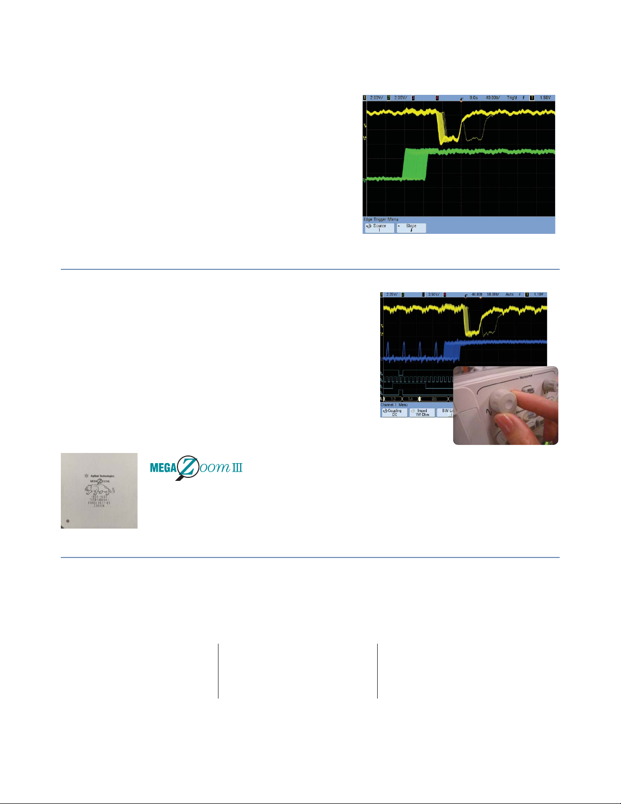
Mixed signal trigger.
Trigger across any combination of analog and digital signals simultaneously. See precise analog measurements timed with exact digital content, all in one box.
Applications for digital channels.
Designing with Altera or Xilinx FPGAs? Use the FPGA dynamic probe for rapid internal
FPGA measurements. Using I2C, SPI, or RS-232? Use the analog or digital signals from
a 4-channe model to acquire and decode these serial buses.
Serial: Hardware-accelerated decode
and trigger for I
2
S
and I
4
2
C, SPI, RS-232, CAN, LIN
Capture long streams of serial data and gain fast insight into your problems. Agilent
6000 Series oscilloscopes provide the best serial protocol capabilities in their class
Serial bus triggering and decoding.
Display responsive, on-screen decode of serial bus traffi c. Isolate specifi c events with
pinpoint accuracy. Show decode to validate serial bus activity in real time.
Quickly fi nd infrequent errors.
Hardware-accelerated decoding increases your probability of capturing elusive events.
Agilent oscilloscopes can help you catch that intermittent problem before it becomes
an intermittenn customer complaint or quality concern.
Easily capture enough serial data to see all of the details.
Use deep memory to capture serial data stream over a long period of time.
Listing Display Window
Shows a tabular view of all captured packets that match on screen waveform data.
Other useful features
High resolution mode. Offers up to 12
bits of vertical resolution in real-time,
single-shot mode. This is accomplished
by serially fi ltering sequential data points
and mapping the fi ltered results to the
display when operating at time base settings greater than 10-μs/div.
Help is at your fi ngertips. An embedded
help system – available in 11 languages
– gives you quick answers if you don’t
understand a feature. Simply press and
hold the corresponding front-panel key,
and a screen pops up to explain its function.
Waveform math with FFT. Analysis functions include subtract, multiply, integrate,
square root, and differentiate, as well as
fast Fourier transforms (FFT).
Peak detect. 250 ps on 500-MHz and 1GHz models, 500 ps on 350-MHz models
and 1 ns on 100-MHz models helps you
fi nd narrow glitches.
AutoProbe interface. Automatically sets
probe attenuation factors and provides
power for selected active probes, including the award-winning 1130A 1.5-GHz
Infi niiMax differential active probe and
1156A 1.5-GHz single-ended active probe
systems.
5-digit hardware counter. Measures
frequency up to the bandwidth of the
scope.
Trig Out and Reference Clock In/Out.
Provides an easy way to synchronize
your scope to other instruments. Use the
Trig Out port to connect your scope to a
frequency counter for more accurate frequency measurements or to cross trigger
other instruments.
Autoscale. Displays all analog and digital
active signals, and automatically sets the
vertical, horizontal and trigger controls.
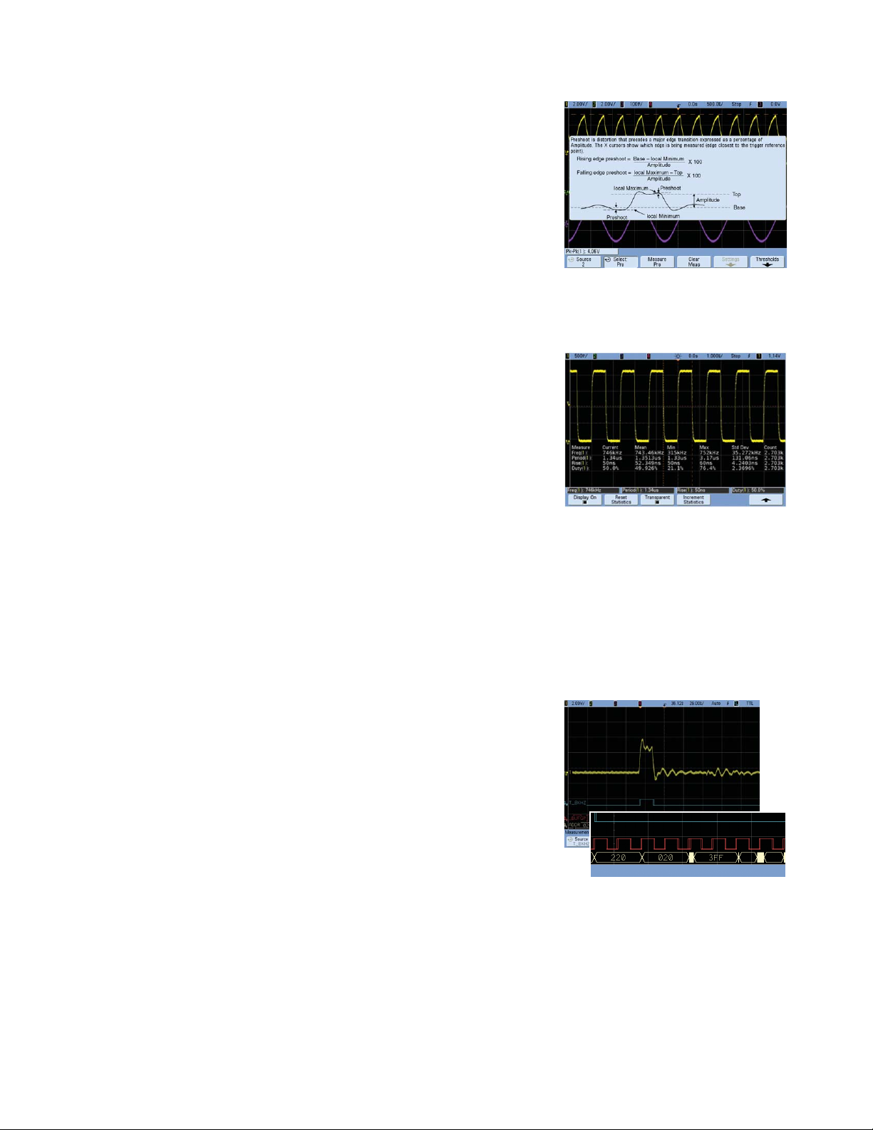
23 automatic measurements with
statistics
measurements with 5 additional statistics
beyond the current value. Fast update
rate provides statistical data for enabled
measurements such as mean, min, max,
standard deviation and count. Pressing
[QuickMeas] brings up the last four automated measurements selected. Cursors
automatically track the most recently
selected measurement.
Analog HDTV/EDTV trigger. The 6000
Series comes standard with analog
HDTV/EDTV triggering for standards
like 1080i, 1080p, 720p and 480p as well
as standard video triggering on any line
within a fi eld, all lines, all fi elds and odd
or even fi elds for NTSC, SECAM, PAL and
PAL-M video signals.
Bus mode display (on MSO models).
Quick and easy read-out of hexadecimal
or binary representation of logic signals.
Easy software upgrades. System
software is stored in fl ash ROM that can
be upgraded from the scope’s built-in
USB port or LAN. You can fi nd the latest
system and IntuiLink software at: www.
agilent.com/fi nd/mso6000sw
Get up to 4 simultaneous
Press and hold a key for instant help.
Measurement statistics allow you
to have confi dence in your measurements. Statistics can show that a
measurement is not only correct at
one moment, but that it has stabilized
and has a low variance over time,
giving it a higher statistical validity.
Digital signals can be displayed individually or as overlayed bus values.
5
Why does a fast update rate matter?
While bandwidth, sample rate and memory depth are key criteria
for deciding which scope to purchase, an equally important char-
acteristic is update rate.
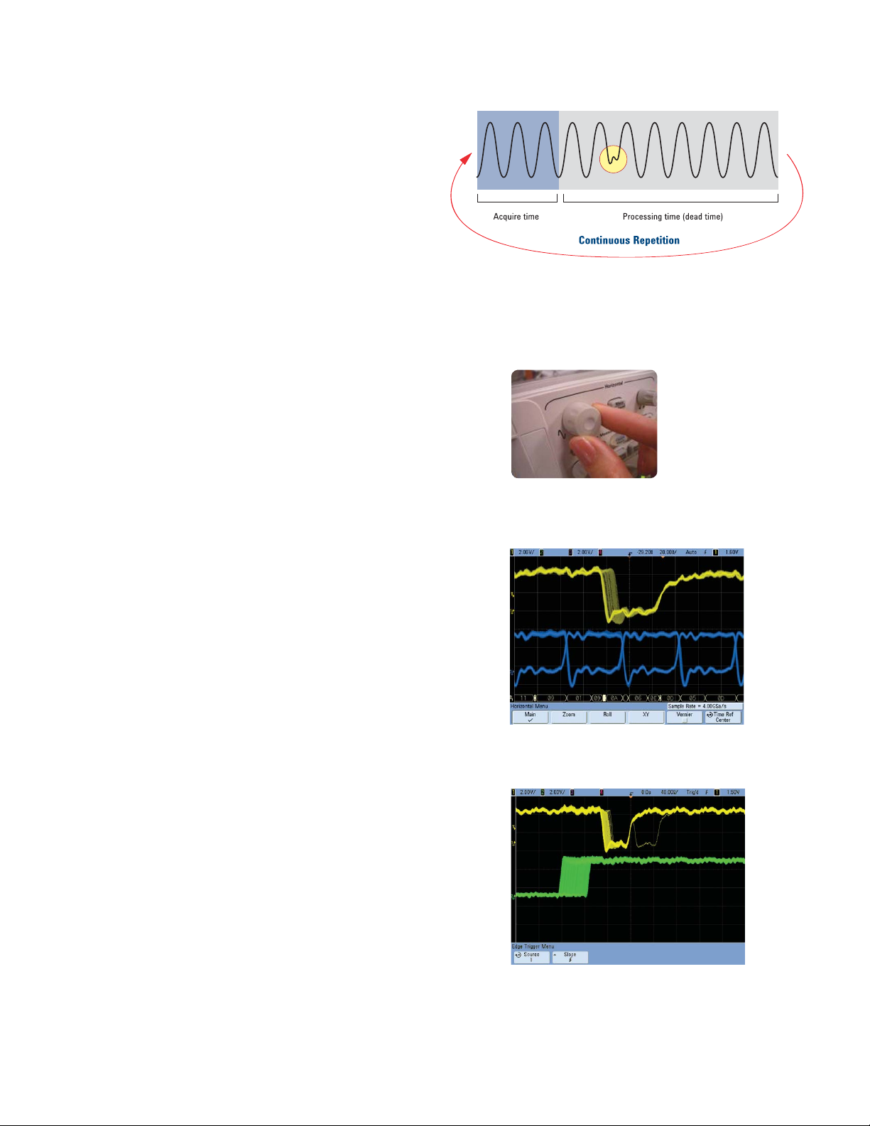
What is update rate?
Update rate is how many waveforms acquisitions per seconds
you scope can acquire, process, and display. Oscilloscope “deadtime” is the time it takes for a scope to process and then display
an acquired waveform before re-arming it’s triggering for the next
acquisition. For traditional scopes, this time is often orders of
magnitude greater than acquisition time on fast time-per-division
settings.
If a glitch occurs during the scope’s dead-time, it won’t be
captured. The key to improving the probability of capturing a
signal anomaly during the scope acquisition time is to minimize
dead-time.
Oscilloscope vendors usually specify what their scope’s “bestcase” waveform update rates are. Some scope architectures
suffer from factors that can seriously degrade the “best-case”
update rates spec. Agilent’s 6000 Series architecture delivers the
world’s fastest update rate when using:
Improves instrument responsiveness
•
Why is update rate important?
1. Responsiveness. If you rotate the timebase control, you ex-
2. Signal detail. Fast waveform update rates improve the
3. Certainty. Fast waveform update rates improve the scope’s
Update rates directly affect a scope probability of capturing and
displaying infrequent and random events. Slow update rates will
cause a scope to miss subtle or infrequent signal details.
Analog channels
•
Deep memory
pect the oscilloscope to respond immediately – not seconds
later after the scope fi nishes processing data.
display quality of the waveform that you see on screen.
probability of capturing random and infrequent events.
•
Analog and digital
•
Serial decode
Improves scope display quality
Improves probability of capturing
infrequent events
6
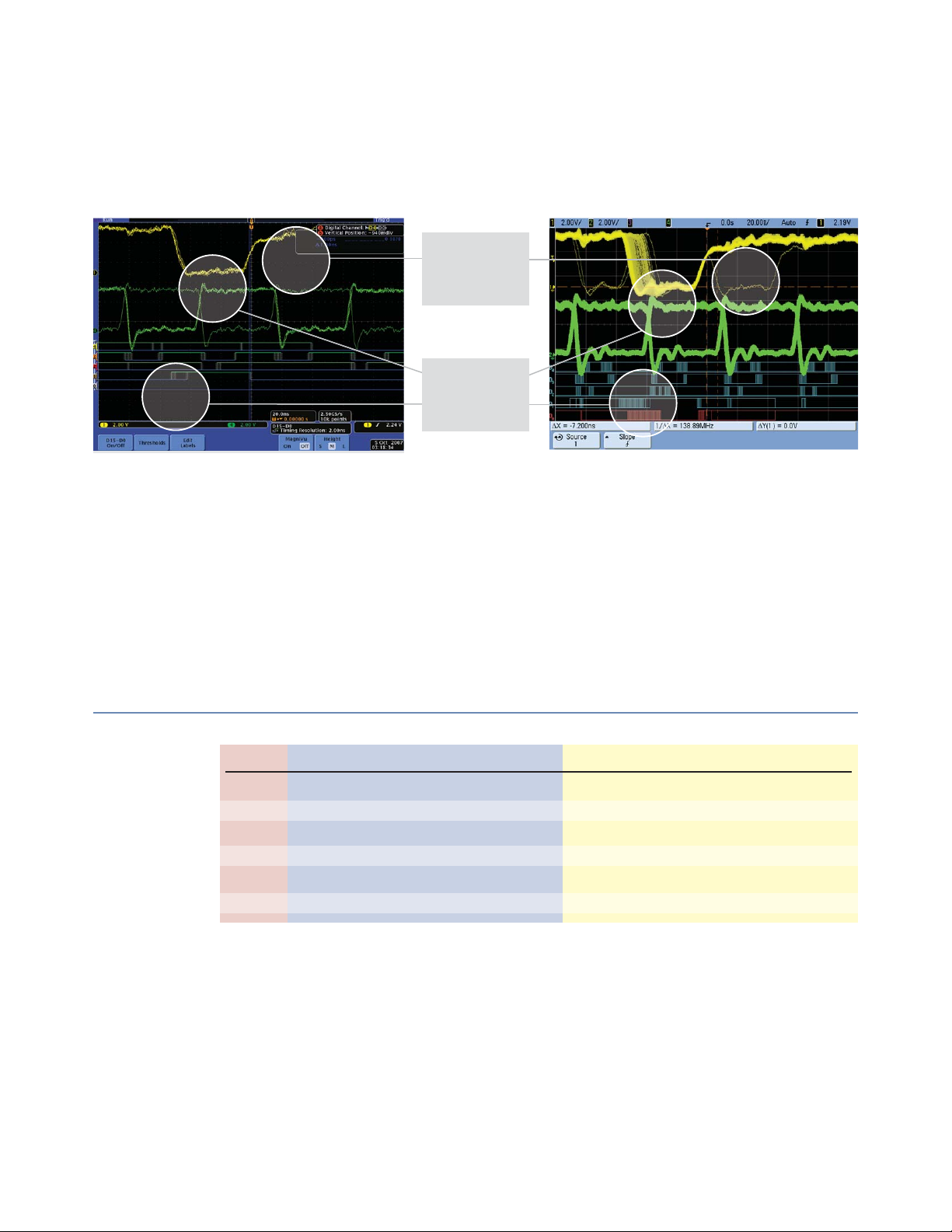
How update rate affects signal visibility
Capturing random and infrequent events on an oscilloscope is all about statistical probabilities. The key to improving the probability of capturing a signal anomaly is to minimize dead-time and take more pictures of the signal in a given timeframe. Here is
an example with Tek and Agilent scopes both connected to a target with a glitch that occurs 25 times per second.
?
?
?
Tek MSO4104
•
Product data sheet: 50,000 waveforms per second.
•
Update rate = 18 waveforms per second with
10 Mpts and digital channels turned on. Resulting
measurement shown.
•
Probability of capturing the infrequent glitch = 0.09%
after running for 10 seconds.
•
Average time to capture just one glitch = 128 minutes.
Infrequent
signal activity
Critical
signal jitter
Agilent MSO6104A
•
Product data sheet: 100,000 waveforms per second.
•
Update rate = 95,000 waveforms per second with auto
memory and digital channels turned on. Resulting
measurement shown.
•
Probability of capturing the infrequent glitch = 99%
after
running for 10 seconds.
•
Average time to capture just one glitch = 1.5 seconds.
Memory* Scope settings Measured update rates
Te k
Initial setup
Change timebase
Add digital channels
Increase memory setting
Turn on serial decode
* Agilent and LeCroy memory depth selection was automatically selected. Memory depth = display window times sample rate with up to 8 Mpts for Agilent.
** Tek measurements taken with version 2.13 fi rmware.
10 Kpts
10 Kpts
10 Kpts
10 Mpts
10 Mpts
Timebase setting
20 ns/div
10 ns/div
20 ns/div
20 ns/div
20 ns/div
Digital Channels
-
-
On
On
On
Serial Decode
-
-
-
-
On
TEK MSO4104A**
55,000
2,700
125
35
0.2
LeCroy WR 104Xi
27
27
27
27
25
Agilent MSO6104A
95,000
95,000
95,000
95,000
95,000
Seeing subtle signal detail and infrequent events requires a scope with fast waveform update rates. Don’t take a scope vendor’s
banner waveform update rate specifi cation at face value. Test it yourself. It’s actually pretty easy to characterize a scope’s
update rate. Run a moderately fast signal (e.g. 50 Mhz) into a scope channel. Measure the scope’s average trigger output signal
frequency. This is your scope’s update rate for the specifi ed timebase setting. Test the update rate of the scope under various
setup conditions. Setup conditions that Agilent suggests varying include timebase range, memory depth, and number of channels, including analog, digital, as well as channels assigned for serial decoding.
7

Software applications
View on-screen serial decode of an I2C packet.
Trigger on and decode RS-232/UART
transmission.
I2C/SPI serial trigger and decode (N5423A or Option LSS on new scope purchases)
2
This application displays real-time time-aligned decode of I
C and SPI serial buses.
Hardware-accelerated decode means the scope stays responsive and fast.
This application requires a 4-channel DSO or 4-channel MSO and can use any combinatio of the scope or logic acquisition channels.
For more information:
www.agilent.com/fi nd/I
2
C-SPI
RS-232/UART serial decode and trigger (N5457A or Option 232 on new scope purchases)
Does your design include RS-232 or another type of UART? This application eliminates
the need to manually decode bus traffi c. Using data captured on the scope or logic
channels, the application lets you easily view the information sent over a RS-232 or
other UART serial bus.
Display real-time time-aligned decode of transmit and receive lines. The application
also enables triggering on RS-232/UART conditions.
This application requires a 4-channel DSO or 4-channel MSO and can use any combination of the scope or logic acquisition channels.
For more information:
www.agilent.com/fi nd/RS-232
Mask testing uncovers an infrequent signal
anomaly.
Use segmented memory to optimize
available memory.
Mask testing (N5455A or Option LMT)
Agilent’s mask test option (Option LMT or N5455A) for Infi niiVision Series oscilloscopes provides a fast and easy way to test your signals to specifi ed standards,
and uncover unexpected signal anomalies, such as glitches. Mask testing on other
oscilloscopes is based on software-intensive processing technology, which tends
to be slow. Agilent’s Infi niiVision scopes can perform up to 100,000 real-time
waveform pass/fail tests per second. This provides testing throughput signifi cantly faster than other mask test solutions, making valid pass/fail statistics available
almost instantly.
For more information: www.agilent.com/fi nd/masktest
Segmented memory (N5454A or Option SGM on new scope purchases)
Segmented memory optimizes available memory for data streams that have long dead
times between activity. The application excels at analyzing signal activity associated
with laser pulses, serial buses, and bursty signals such as radar. View an overlay of
all signal segments, including MSO channels and serial decode, while highlighting the
current segment. Quickly move between segments to view signal detail associated
with a specifi c segment.
This application works with all DSO and MSO models.
For more information: www.agilent.com/fi nd/segmented
8

Software applications
On-screen serial decode of an SPI packet
I2S triggering and decode(Option SND or N5468A)
Find and debug intermittent errors and signal integrity problems faster on I2S audio
protocol devices. This application offers powerful triggering and our unique hardwareaccelerated decode and lister window so you can more easily fi nd errors you could
miss using other serial bus decode tools.
This application requires a 4 channel DSO or MSO model
For more information: www.agilent.com/fi nd/I2S
CAN/LIN triggering and decode (N5424A or Option AMS on new scope purchases)
Trigger on and decode serially transmitted data based on CAN and LIN protocols. This
application not only provides triggering on complex serial signals, but it also provides
unique hardware-accelerated capabilities. Hardware-accelerated triggering and decode
means the scope stays responsive and fast.
This application requires a 4-channel DSO or 4-channel MSO and can use any combination of scope or logic acquisition channels.
Trigger on and decode CAN serial packets.
Debug and validate your FPGA designs
faster and more effectively with the FPGA
dynamic probe and an Agilent MSO.
Use your scope to quickly make and
analyze power measurements.
For more information: www.agilent.com/fi nd/CAN-LIN
FPGA dynamic probe application (N5406A for Xilinx, N5434A for Altera)
Give your MSO internal FPGA visibility. Agilent’s MSO FPGA dynamic probe provides
internal FPGA visibility and quick instrument setup using an innovative core-assisted
debug approach. Measurement tasks that previously took hours can be done in a few
mouse clicks. In a few seconds, easily measure a different set of internal signals without changing your FPGA design.This application works with all MSO models.
For more information:
www.agilent.com/fi nd/6000-altera
www.agilent.com/fi nd/6000-xilinx
Power application (U1881A)
Need to make power measurements with your scope? Agilent’s power application provides a full suite of power measurements that run on a PC connected to an Infi niiVision 6000 Series oscilloscope. Make more accurate power supply effi ciency measurements by using an U1880A deskew fi xture to deskew your voltage and current probes.
This application works with all DSO and MSO models.
For more information: www.agilent.com/fi nd/power-app
9
 Loading...