


Errata
8903E Operation & Calibration
Manual
08903-90053
July 1985
Title & Document Type:
Manual Part Number:
Revision Date:
HP References in this Manual
This manual may contain references to HP or Hewlett-Packard. Please note that HewlettPackard's former test and measurement, semiconductor products and chemical analysis
businesses are now part of Agilent Technologies. We have made no changes to this
manual copy. The HP XXXX referred to in this document is now the Agilent XXXX.
For example, model number HP8648A is now model number Agilent 8648A.
About this Manual
We’ve added this manual to the Agilent website in an effort to help you support your
product. This manual provides the best information we could find. It may be incomplete
or contain dated information, and the scan quality may not be ideal. If we find a better
copy in the future, we will add it to the Agilent website.
Support for Your Product
Agilent no longer sells or supports this product. You will find any other available
product information on the Agilent Test & Measurement website:
www.tm.agilent.com
Search for the model number of this product, and the resulting product page will guide
you to any available information. Our service centers may be able to perform calibration
if no repair parts are needed, but no other support from Agilent is available.

a
a
e
HP
8903E
Distortion Analyzer
Operation and
Calibration Manual
a
a
e
e
0
0
e
a
e
e
a
:.
.e.
.....
...e
.....
. . ..
00..
Ag
i
I
en
t
Techno
Io
g i es

HP
8903E
DISTORTION
(Including
SERIAL
This manual applies directly to instruments with
serial numbers prefixed
For additional important information about serial
numbers, see
Section
Instruments Covered
1.
First Edition
ANALYZER
Option
NUMBERS
2507A
and
001)
2516A.
by
Manual
in
@HEWLET-PACKARD COMPANY
EAST 24001 MISSION AVENUE, TAF C-34, SPOKANE, WASHINGTON,
Operation and Calibration Manual Part
Operation and Calibration Manual Microfiche Part
No.
08903-90053
No.
90069
1985
USA.,
99220
Printed:
JULY 1985

1
Regulatory
Information
(Updated
March
1999)
1

Regulatory Information
Safety Considerations
GENERAL
This product and related documentation must be reviewed for familiarization with safety
markings and instructions before operation.
(Updated
March
1999)
This product has been designed and tested in accordance with
"Safety Requirements for Electronic Measuring Apparatus," and has been supplied in a
safe condition. This instruction documentation contains information and warnings which
must be followed by the user to ensure safe operation and
condition.
SAFETY
A
uninterruptible safety earth ground must be provided from the main power source
product input wiring terminals, power cord, or supplied power cord set.
SAFETY
A
Indicates instrument
Indicates hazardous voltages.
Indicates earth (ground) terminal
WARNING
EARTH GROUND
SYMBOLS
damage
A
WARNING
practice, or the like, which, if not correctly performed or adhered to,
could result in personal
sign until the indicated conditions are
can occur if indicated operating limits are exceeded.
note denotes a hazard. It calls attention to a procedure,
injury.
Do
not proceed beyond a
fulls
IEC
Pubhation
to
maintain the product in a safe
WARNING
understood and met.
101
0,
to
the
CAUTION
A CAUTION note denotes a hazard.
procedure, practice, or the like, which, if not correctly performed or adhered
to, could result in damage
not proceed beyond an CAUTION note until the indicated conditions are fully
understood and met.
to
or
It
calls attention to an operation
destruction
of
part
or
all of the product.
Do
2
Chapter
1

Safety Considerations for this Instrument
Regulatory Information (Updated
March
1999)
WARNING
This product is a Safety Class I instrument (provided with a
protective earthing ground incorporated in the
power
cord). The
mains plug shall only be inserted in a socket outlet provided with a
protective earth contact. Any interruption of the protective
or
conductor inside
outside of the product
product dangerous. Intentional interruption
Whenever
it
is
likely that the protection has been impaired, the
is
likely to make the
is
prohibited.
instrument must be made inoperative and be secured against any
unintended operation.
If
this instrument is to be energized
voltage reduction), make sure the common terminal is connected
the earth terminal
If
this product
of
is
not used
the power source.
as
specified, the protection provided by
via
an auto transformer (for
to
the equipment could be impaired. This product must be used in a
normal condition (in which all means for protection are intact) only.
No
operator serviceable parts in this product. Refer servicing to
qualified personnel. To prevent electrical shock, do not remove
covers.
Servicing instructions are for use by qualified personnel only.
To
avoid electrical shock, do not perform any servicing unless you are
qualified to do
so.
The opening of covers
dangerous voltages. Disconnect the product from
while
it
is
being opened.
The power cord is connected to internal capacitors that
live
for 5 seconds after disconnecting the plug from its power supply.
or
removal of parts
is
likely to expose
all
voltage sources
my
remain
For Continued protection against fire hazard, replace the line fuse(s)
only with
example, normal blow
250
V
fuse(s)
or
the same current rating and type
or
time delay). Do not use repaired fuses or
(for
short circuited fuseholders.
Always use the three-prong ac power cord supplied with this
product. Failure to ensure adequate earth grounding by not using
this cord may cause product damage.
This product
Pollution Degree
INDOOR
is
USE
designed
2
per
ONLY.
for
IEC
use in Installation Category
1010
and
IEC
664
respectively.
I1
and
FOR
This product has autoranging line voltage input, be sure the supply
voltage
is
within the specified range.
Chapter
1
3

Regulatory Information
(Updated
To
prevent electrical shock, disconnect instrument
before cleaning, Use a dry cloth or
to clean the external case
Ventilation Requirements: When installing the product in a cabinet,
the convection into and out
The ambient temperature (outside the cabinet) must be less than the
maximum operating temperature of the product by
watts dissipated in the cabinet. If the total power dissipated in the
cabinet
used.
Product Markings
March
1999)
is
greater than
from
one
slightly dampened with water
parts.
800
Do
not attempt
of
the product must not be restricted.
to
clean internally.
4"
C
for every
watts, then forced convection must be
mains (line)
100
CE - the CE mark
accompanied
CSA - the
by a year indicated the year the design was proven.
CSA
mark
is a
registered trademark
is
a
registered trademark
of
the European Community. A CE mark
of
the
Canadian Standards Association.
Chapter
1

Model
89033
Safety Considerations
SAFETY
GENERAL
This product and related documentation must be reviewed for familiarization with safety markings and
instructions before operation.
This product is a Safety Class I instrument (provided
with a protective earth terminal).
BEFORE APPLYING POWER
Verify that the product is set to match the available
is
line voltage and the correct fuse
SAFETY EARTH GROUND
An uninterruptible safety earth ground must be provided from the main power source to the product input
wiring terminals, power cord,
set.
SAFETY SYMBOLS
Instruction manual symbol: the product will
be marked with this symbol when it
is necessary for the user to refer to the instruction
manual (refer to Table of Contents).
Indicates hazardous voltages.
f
Indicates earth (ground) terminal.
The WARNING sign denotes a
hazard.
procedure, practice, or the like, which,
performed
jury.
the indicated conditions are fully understood and met.
or
adhered to, could result in personal in-
Do
not proceed beyond a WARNING sign until
It
installed.
or
supplied power cord
calls attention to a
if
CONSIDERATIONS
not correctly
Any interruption of the protective (ground-
or
ing) conductor (inside
or
ment)
terminal will cause a potential shock hazard
that could result in personal injury. (Grounding one conductor of a two conductor outlet
is not sufficient protection).
Whenever it is likely that the protection has
been impaired, the instrument must be made
inoperative and be secured against any unintended operation.
If this instrument is to be energized via
autotransformer (for voltage reduction) make
sure the common terminal is connected to the
earth terminal of the power source.
Servicing instructions are for use by service-
trained personnel only.
electric shock, do not perform any servicing
unless qualified to
Adjustments described
formed with power supplied to the instrument
while protective covers are removed. Energy
available at many points may,
sult in personal injury.
Capacitors inside the instrument may still be
charged even if the instrument has been disconnected from its source of supply.
disconnecting the protective earth
do
outside the instru-
To
avoid dangerous
so.
in
the manual are per-
if
contacted, re-
an
The CAUTION sign denotes a hazard.
It
calls attention to an
operating procedure, practice, or the like, which,
correctly performed
or
age to
not proceed beyond a CAUTION sign until the indicated conditions are fully understood and met.
destruction of part or all
or
adhered to, could result in dam-
of
the product.
if
not
Do
For
continued protection against fire hazard,
replace the line fuse(s) only with
of the same current rating and type (for example, normal blow, time delay, etc.).
or
repaired fuses
fuseholders.
short circuited
250V
Do
fuse(s)
not use
...
111

Safety Considerations Model
ATTENTION
Static Sensitive
Devices
89033
This instrument was constructed
charge) protected environment. This is because most of the semi-
in
conductor devices used
by static discharge.
Depending on the magnitude of the charge, device substrates can
or
be punctured
charge. The results can cause degradation of device performance,
early failure,
These charges are generated
tact, separation of materials, and normal motions of persons
working with static sensitive devices.
When handling
devices, adequate precautions must be taken to prevent device dam-
age
or
destruction.
Only those who are thoroughly familiar with industry accepted
techniques for handling static sensitive devices should attempt to
service circuitry with these devices.
In all instances, measures must be taken to prevent static charge
build-up on work surfaces and persons handling the devices.
For further information on ESD precautions, refer to “SPECIAL
HANDLING CONSIDERATIONS FOR STATIC SENSITIVE
DE VICES”
destroyed by contact
or
immediate destruction.
or
in
Section VIII Service Section.
this instrument are susceptible to damage
in
servicing equipment containing static sensitive
in
an ESD (electro-static dis-
or
mere proximity of a static
numerous ways such
as
simple con-
iv

Model
8903E
CONTENTS
Table
of
Contents
VOLUME
Section
GENERAL INFORMATION
Introduction
Specifications
Safety Considerations
Instruments Covered by Manual
Serial Numbers
Options
Manual Changes Supplement
Audio Testing
Balanced Input
Transceiver Testing
Systems
Options
Electrical Options
Electrical Option
Internal Plug-in Filter Options
Mechanical Options
Front Handle Kit (Option
Rack Flange Kit (Option
Rack Flange and Front Handle
Combination Kit (Option
Hewlett-Packard Interface
BUS (HP-IB)
Compatibility
Selecting the HP-IB Address
Accessories Supplied
Electrical Equipment Available
HP-IB Controllers
Front-to-Rear-Panel Connectors
Retrofit Kit
Rear-to-Front-Panel Connectors
Retrofit Kit
Mechanical Equip
Available
Chassis Slide Mount Kit
Chassis Tilt Slide Mount Kit
Recommended Test Equipment
Principles of Operation for
Simplified Block Diagram
Voltmeter and Notch Filter
Counter
Voltage Measurement
Input Frequency Measurement
Controller
Basics of Audio
AC Level
Frequency
DC Level
Signal Impurities
Distortion
SINAD
.....................
............
.............................
..............................
.............................
................................
..........................
......................................
........................................
.............................
001
........................
...........................
908)
.................................
.............................
.............................
................................
.....................................
.......................
.
......................................
........................
.
.
.......................
....................................
....................................
..............
........
1
1
..........
.....................
..................
......
.................
.................
................
907)
...............
................
909)
...................
...................
...............
.
...................
.........
................
..................
.........
..............
............
........
.
...
Page
.
1-1
1-1
1-1
1-1
.
1-2
1-2
1-2
1-2
1-2
1-3
1-3
1-3
1-3
1-3
1-3
1-4
1-4
1-4
1-4
1-4
1-4
1-4
1-4
1-4
1-4
1-4
1-6
1-6
1-6
1-6
1-6
1-7
1-8
1-8
1-9
1-9
1-9
Section
INSTALLATION
2
................................
................................
Preparation for Use
Power Requirements
Line Voltage and Fuse Selection
Power Cables
HP-IB Address Selection
Interconnections
Mating Connectors
Interface Connector
Coaxial Connectors
Operating Environment
Bench Operation
Rack Mounting
Storage and Shipment
Environment
Packaging
Original Packaging
Other Packaging
Introduction
General
Operatingg Characteristics
Turn-On Procedure
Local Operation
Simplified Operation
Panel Features
Detailed Operating Instructions
Supplemental Information
Remote Operation (HP-IB)
Operator’s Checks
Basic Functional Checks
HP-IB Functional Checks
Operator’s Maintenance
Operator’s Checks
Basic Functional Checks
Preliminary Check
Filter Check
Distortion
SINAD Check
DC Level Check
HP-IB Functional Checks
Address Recognition
Remote and Local Messages and the LCL Key
Sending the Data Message
Receiving the Data Message
Local Lockout and Clear
Lockout/Set Local M
Clear Message
Abort Message
Status Byte Message
Require Service Message
Trigger Message and Clear
Key Triggering
....................................
.......................
......................................
.............................
...........................
................
.................................
.......................
..............................
............................
.........................
..........................
........................
..............................
...............................
...........................
.................................
.............
...............
Section
OPERATION
3
......... .........
............................
...............................
.........................
.......................
........
....................
.........
.............................
.....................
....................
........................
...............................
........
...........
................................
.................................
.............................
...........................
.....................
........................
..................
.................
...............
.......
.............................
.......................
....................
...........................
Page
.
2-1
2.1
2-1
2-1
2-1
2-1
2-2
2-4
2-4
2-4
2-4
2-4
2-5
2-5
2-5
2-5
2-5
3-1
3-1
3-1A
3-1
3-2
3-2
3-2
3-2
3-2
3-2
3-8
3-9
3-10
3-10
3-10
3-11
3-11
3-12
3-13
3-13
3-13
3-14
3-15
3-16
3-17
3-17
V

Table
of
Contents
Model
89033
Remote Operation, Hewlett-Packard
Interface Bus
HP-IB Compatibility
...........................
.
.
............
.......................
....................
Local Mode
Local Capability
Remote-to-Local Mode Changes
Addressing
Local Lockout
Data Messages
Receiving the Data Message
Listen Only
Data Input Format
Program Codes
Turning Off Functions
Programming Numeric Data
General Numeric Data Input Format
Triggering Measurements with the
Data Message
Special Considerations for
Triggered Operation
Reading Data from the Right
or Left Display
Program Order Considerations
Sending the Data Message
Talk Only Mode
Talk Status Only Mode
Data Output Format
Data Output Format
Error Output Format
Receiving the Clear Message
Receiving the Trigger Message
Receiving the Remote Message
Receiving the Local Message
Receiving the Local
Lockout Message
Receiving the Clear Lockout/Set
................
......................
.........
...............
........................
......................
..............
..........................
....................
.......................
............
...
.......................
..............
.....................
...............
......................
....
..................
..................
..............
.............
............
.
..........
.....................
Receiving the Pass Control Message
Sending the Require Service Message
Selecting the Service Request
Condition
Sending the Status Byte Message
Sending the Status Bit
Receiving the Abort Message
HP-IB Syntax and Characteristics
Summary
...................
.......................
.............
....
....................
CONTENTS
Page
-
3-19
3-19
3-19
3-19
........
........
.
...........
........
....
......
.....
3-19
3-19
3-19
3-19
3-21
3-21
3-21
3-22
3-22
3-23
3-23
3-24
3-24
3-25
3-25
3-25
3-25
3-26
3-26
3-26
3-26
3-26
3-26
3-27
3-29
(cont’d)
DETAILED OPERATING INSTRUCTIONS
..........................
ion
......................
Common Mode
DC Level
Default Conditions and Power-up
Sequence
Detector Selection
Display Level in Watts
Distortion
Error Disable
Error Message Summary
Filters
Hold Settings
HP-IB Address
Input Level Range (DC Level)
Input Level Range (Except DC Level)
Monitor
Notch Tune
Post-Notch Detector Filtering
Post-Notch Gain
Rapid Frequency Count
RATIO and LOG/LIN
Read Display to HP-IB
Service Request Condition
SINAD
Special Functions
Time Between Measurements
Introduction
Equipment Required
Test Record
Calibration Cycle
Abbreviated Performance Testing
PERFORMANCE
AC Level Accuracy
DC Level Accuracy
Residual Distortion and Noise
Distortion and SINAD Accuracy
Frequency Accuracy and Sensitivity
Audio Filters
Input Impedance
Common-Mode Rejection Ratio
Performance Test Record
.........................
(Except SINAD)
..................................
.......... .............
...............
.............
....................
..............
...............
.....
...................
...................
..............
...................
..........................
nt
.......................
.............................
...........................
.............
.................
..............
........................
...........
....................
....................
..............
.................
......
...............
...............
Section
PERFORMANCE TESTS
4
....................
............
...............................
..........................
TESTS
..................
.........................
............
.....
.............................
................
. ......
...... ......
......
......
.......
...........
...........
.........
............
.........
......
Page
-
3-33
3-33
3-35
3-36
3-39
3-43
3-45
3-47
3-48
3-51
3-55
3-57
3-58
3-59
3-61
3-62
3-64
3-67
3-68
3-69
3-70
3-73
3-75
3-76
3-78
3-80
3-86
4-1
4-1
4-1
4-2
4-2
4-14
4-15
4-22
4-24
4-26
vi

Model
89033
Table
of
Contents
Section 5
ADJUSTMENTS
Introduction
Safety Considerations
Equipment Required
. . .
.
.
. .
. .
. .
. . . . . . .
. . .
.
. . . .
.
Factory-Selected Components
Post-Repair Tests,
Adjustments, and Checks
Related Adjustments
ADJUSTMENTS
. .
. . .
. . . . . . . . .
. . . . . . . . . . .
Internal Reference Frequency
CONTENTS
. . . .
.
.
.
. .
. . . .
. . . . . .
.
.
. . . . . .
.
. . . . . . . . .
.
. . . . . . . . . . . . . . .
. . . . . . . .
. . .
. . .
. . . . . . . . . .
. . . . . . .
. .
. . . . .
. .
.
. . . .
. .
. .
.
. .
. . . . .
. . . . . .
.
. .
.
. .
Page
-
5-1
5-1
5-1
5-1
5-1
5-2
5-3
5-3
(cont’d)
Input Flatness
Common-Mode Rejection
Input DC Offset
400
Hz High-Pass and Weighting
Bandpass Filters
Notch Filter Tune and Balance
Voltmeter (Using
Controller)
Voltmeter (Not Requiring an HP-IB
Controller)
. . . . . . . . . . . .
. .
. . . . . . . . . . . . .
. . .
.
. . .
an
HP-IB
. . . .
.
. . .
.
. . .
. . . . . . . . . . .
.
.
.
.
. . .
.
.
. .
.
.
.
. . . . . . . .
. .
.
. . .
.
. .
. . .
. . . . .
. .
. .
. .
. . . . . . .
. .
. .
. . . .
. . . . . . . .
. . . .
. . . .
. . .
. . . .
.
. . . . . .
. . .
. .
. . . . . .
.
. .
. . .
. .
.
. .
5-4
5-8
.
5-9
5-10
5-12
5-13
5-16
vii

Model 89033
General Information
Section
GENERAL
1-1.
INTRODUCTION
This manual contains information required to install,
operate, test, adjust, and service the Hewlett-Packard
Model 89033 Distortion Analyzer. This manual documents options installed in the Distortion Analyzer
such as rear-panel connections and internal plug-in
filters.
This section of the manual describes the instruments
documented by the manual and covers instrument
description, options, accessories, specifications, and
other basic information. This section also contains
principles of operation on a simplified block diagram
level and basic information on audio measurements.
The other sections contain the following
information:
Section
initial inspection, preparation for use (including address selection for remote operation), and storage and
shipment.
Section
panel features, and includes operating checks, operating instructions
and maintenance information.
Section
tion required to check performance
against the critical specifications in Table
Section
required to properly adjust the instrument.
Section
formation for all replaceable parts and assemblies.
Section
modification, recommendations, and procedures.
Section
to repair the instrument.
Sections 1 through 5 are bound
Operation and Calibration Manual.
8
are bound in
ual.
Service Supplement,
Copies of the
the instrument unless specifically requested
915) at time
Calibration Manual
order. When option
2,
Installation:
3,
Operation:
for
4,
Performance Tests:
5,
Adjustments:
6,
Replaceable Parts:
7,
Instrument Changes:
8,
Service:
two
The
Service Manual
Service Manual
of
instrument order. The
provides information about
provides information about
both local
provides the information required
separate volumes, the
and
an
and
remote operation,
provides the informa-
of
the instrument
1
-
1.
provides the information
provides ordering in-
provides instrument
in
this volume, the
Sections 6 through
Service Man-
is comprised of
an
HP
8903E
HP 8903B Service Manual.
are not supplied with
(as
option
Operation and
is supplied with the instrument
915
is requested, the complete
1
INFORMATION
service manual (the
the
HP8903B Service Manual)
instrument order.
Copies of all volumes can be ordered through your
nearest Hewlett-Packard sales office. The part numbers are listed on the title page of this manual.
Also listed on the title page
the manual part number, is
This number may be used to order 100
(4
X
6
inch) microfilm transparencies of this manual.
Each microfiche contains up to
of the manual’s pages. The microfiche package also
includes the latest
ments, as well as all pertinent Service Notes.
1-2.
SPECIFICATIONS
Instrument specifications are listed in Table
These are the performance
which the instrument may be tested. Characteristics
listed under Supplemental Information, Table 1-2,
are not warranted specifications but are typical characteristics included as additional information for the
user.
1-3.
SAFETY
This product
provided with a protective earth terminal). The
Distortion Analyzer and all related documentation
must be reviewed for familiarization with safety markings and instructions before operation. Refer to the
Safety Considerations
of this manual for a summary of the safety informa-
tion. Safety information pertinent
(installation, performance testing, adjustment,
service) is found throughout the manual.
1-4.
INSTRUMENTS COVERED
Serial Numbers.
ial number in the form
on the serial number plate attached to the rear
the instrument. The first four digits and the letter
constitute the serial number prefix, and the last five
digits form the suffix. The prefix
identical instruments. It changes only when a change
is made to the instrument. The suffix, however, is
assigned sequentially and is different for each instrument. The contents of this manual apply directly to
instruments having the same serial prefix(es) as listed
under SERIAL NUMBERS on the title page.
HP
89033 Service Supplement
is
supplied with the
of
this manual, below
a
microfiche part number.
96
photo-duplicates
MANUAL
CHANGES
standards,
or
limits against
CONSIDERATIONS
is
a Safety Class I instrument (that is,
page found at the beginning
to
the task at hand
BY
MANUAL
This instrument has a two-part ser-
OOOOAOOOOO
which is stamped
is
the same for all
X
150 mm
supple-
and
1-1.
or
of
1-1
General Information
Model 89033
Options.
Electrical Option
001,
internal plug-in filter
options, and various mechanical options are documented in this manual. The differences are noted
under the appropriate paragraph such as
Section
1,
the Replaceable
Parts
List, and the sche-
Options
in
matic diagrams.
1-5.
MANUAL CHANGES SUPPLEMENT
An instrument manufactured after the printing of
this manual may have a serial prefix that is not listed
on the title page. An unlisted serial prefix indicates
that the instrument differs in some way from those
documented in this manual.
A
“Manual Changes Supplement”
manual
to
provide you with the most current change
is
shipped with this
information available at the time of shipment. In
to
addition
change information the supplement may
contain information for correcting errors in the
manual.
To keep this manual up
to
date and as accurate as
possible, Hewlett-Packard recommends that you periodically request the latest Manual Changes Supplement. The supplement is identified with the print
date and part number that appears on the title page.
Complimentary copies of the supplement are available
from Hewlett-Packard.
1-6.
DESCRIPTION
1-7.
General
The HP Model 89033 Distortion Analyzer
measurement system covering the frequency range
20Hz
to
100
kHz. The analyzer can perform
is
an audio
of
distortion analysis, frequency count, ac level, dc level,
and SINAD measurements. The Distortion Analyzer
reduces the number of instruments required in many
applications involving audio signal characterization.
The Distortion Analyzer is easy to use. All measure-
or
ments are selected by one
two keystrokes. For
distortion measurements, the Distortion Analyzer
automatically ranges to, and tunes to the input signal.
Measurement and output ranges are automatically
selected for optimum resolution and accuracy.
The combined capabilities of the instrument are enhanced by microprocessor control, resulting in more
capability than would be available from separate
instruments. For example, using the ratio key allows
100%
you to set a
OdB
or
reference for making
frequency response measurements. Microprocessor
control allows flexible and versatile display formats.
For example, ac level can be displayed in V, mV,
600Q2,
dBm into
watts,
referenced to an entered
or
as a ratio (in % ordB)
or
measured value.
Virtually all functions are remotely programmable
through the Hewlett-Packard Interface Bus (HP-IB)‘.
Programming
is
easy and straightforward. All meas-
urements are made through a single input. This elimi-
to
nates the need
switch between multiple inputs
under remote control and reduces software
development time and hardware costs. The Distortion
Analyzer measures the true rms level on all ac measurements. True rms measurements assure greater
accuracy when measuring complex waveforms and
noise. For those applications where average detection
is required, the analyzer can be switched to average
responding (rms calibrated) detection via a frontpanel key. Accurate distortion measurements typically
to
can be made
20
Hz
and
1-8.
Audio Testing
less than 0.003% (-9OdB) between
20
kHz.
The Distortion Analyzer has numerous features which
make audio testing simple and convenient. For
example, distortion results can be displayed in
ora.
volts, dBm into
can be displayed in
or
AC level measurements can be displayed in
600Q,
or
watts. Measurement results
%
or
dB
relative to a measured
entered value. Finding the 3dB points of filters
%
and amplifiers is simplified by using the relative
display feature. The Distortion Analyzer also features
is
20
bet-
Hz to
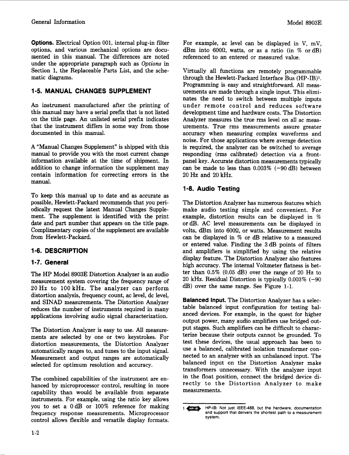
high accuracy. The internal Voltmeter flatness
0.5%
(0.05
dB)
ter than
20
kHz. Residual Distortion is typically 0.003% (-90
dB)
over the same range. See Figure
Balanced Input.
The Distortion Analyzer has a selec-
over the range of
1-1.
table balanced input configuration for testing bal-
anced devices. For example, in the quest for higher
output power, many audio amplifiers use bridged out-
put stages. Such amplifiers can be difficult
to
characterize because their outputs cannot be grounded. To
test these devices, the usual approach has been to
use a balanced, calibrated isolation transformer con-
an
nected to
analyzer with an unbalanced input. The
balanced input on the Distortion Analyzer make
transformers unnecessary. With the analyzer input
in the float position, connect the bridged device directly to the Distortion Analyzer
to
make
measurements.
HP-IB:
I
Not just
and support that delivers the shortest path to a measurement
system.
IEEE-488.
but the hardware, documentation
1-2

Model 89033
General Information
-70
E
w
-75
??
g
-80
U
6
-80
5
-a5
-
I-
a:
-90
--
..
.
Figure
FREQUENCY
1-1.
Typical Analyzer Residual
Distortion
1-9.
Transceiver Testing
The Distortion Analyzer has several measurements
and features specifically designed for transceiver test-
It
ing.
has SINAD measurements for receiver testing,
optional internal plug-in weighting filters for testing
to international standards, a reciprocal counter for
measuring squelch tones, and an optional internal
400
Hz
plug-in
high-pass filter for eliminating squelch
tones when measuring transmitter audio distortion.
SINAD is one of the most basic receiver measure-
ments.
sensitivity
the Distortion Analyzer, the SINAD measurement
It
must be made repeatedly when performing
or
adjacent-channel sensitivity tests. In
is
more heavily filtered than the distortion measurement
to
in order
receiver testing. The filtering
lent repeatability and speed
smooth the noisy signals encountered in
is
optimized for excel-
(2
readingslsecond
typ-
ical). Some automatic distortion analyzers have a
tendency to become untuned when measuring SINAD
on noisy signals. The Distortion Analyzer overcomes
this problem by providing a front panel key which
locks the notch filter at the input frequency.
SINAD ratios less than 25
can be used to round the digital display
cU3,
a Special Function
to
the nearest
For
0.5dl3 to reduce digit flicker.
For
accurate noise ratio measurements, the Distortion
rms
Analyzer uses true
detection for SINAD. Most
older instruments employ average detection which
reads low for noise. The discrepancy can be 1.5dT3
or greater and varies with the ratio being measured.
For
correlating results with past test data, the
Distortion Analyzer’s detector can be switched via a
front-panel key to an average responding
configuration.
For
transceivers, the Distortion Analyzer has an op-
tional, internal plug-in seven-pole
400
Hz
high-pass
filter for rejecting squelch tones. Rejection of squelch
tones up to
audio distortion measurements to
250
Hz
is
greater than
40
dl3.
Therefore,
1
%
residual
distortion can be made without disabling the transmitter squelch tones.
Under remote control, the Distortion Analyzer can
count burst tone sequences. Typically the maximum
count rate is 8 ms/reading.
1-10.
Systems
The Distortion Analyzer features capabilities for general systems applications. The distortion measurements are fully automatic, programmable, and fast.
The typical time to tune and return the first distortion
1.5
measurement is
2
readingslsecond thereafter. The residual
of
distortion of the analyzer is typically
seconds with a measurement rate
0.003%
(-90
dB)
between 20Hz and 20kHz.
Often, systems applications involve measuring low
level ac signals. The Distortion Analyzer features a
full range ac level display of 0.3000mV with an
accuracy of
>50 mV and from
4%
of reading
20
Hz to 20
(2%
of reading for levels
kHz).
The ac detector
is switchable between true rms and average respond-
3
dl3
ing detection. The
both detectors is greater than
measurement bandwidth for
500
kHz.
Since many systems have noise problems, the
80
Distortion Analyzer has both 30 and
filters
to
reject high frequency noise. In addition, the
optional internal plug-in
400
Hz
high-pass filter atten-
uates line-related hum and noise by more than 68
A
special binary programming mode is available in
kHz low-pass
dB.
remote operation. The rapid frequency count mode
provides a packed, four-byte output for fast counting
over HP-IB.
1-1 1.
OPTIONS
1-1
2.
Electrical Options
Electrical Option
001.
This option provides a rear-
panel (instead of front-panel) connection for the
INPUT and MONITOR connectors.
Internal Plug-in Filter Options.
The Distortion
Analyzer has two internal plug-in filter positions;
each position can be loaded with any one of six
its
optional filters. Each filter is referenced to
corre-
sponding filter position by one of two option numbers.
For
example, the
be ordered as Option
left-most filter position,
400
Hz High-Pass Filter Option can
010
which corresponds to the
or
as Option
050
which corresponds to the right-most filter position. These optional plug-in filters can be configured in any
combination desired.
If
there
is
no filter ordered
for
a position, a jumper wire is loaded and a label marked
1-3

General Information Model 89033
“No Filter” is placed above the filter key on the front
panel. The following list includes the name and option
numbers for each available filter.
400 Hz High-Pass Filter (Option 010, 050).
CCITT Weighting Filter (Option 011, 051).
CCIR Weighting Filter (Option
C-MESSAGE Weighting Filter (Option 013, 053).
CCIR/ARM Weighting Filter (Option 014, 054).
“A”
Weighting Filter (Option 015, 055).
Specific information on each plug-in filter option can
be found in the Detailed Operating Instructions in
3
Section
1-13.
The following options may have been ordered and
received with the Distortion Analyzer.
not ordered with the original shipment and are now
desired, they can be ordered from the nearest Hewlett-
Packard office using the part number included in
each
options are shown in Figure 1-2.
under “Filters”.
Mechanical Options
of
the following paragraphs. The mechanical
Front Handle Kit (Option
increased with the front-panel handles. Order HP
part number 5061-9689.
012,
907).
Ease of handling
052).
If
they were
is
the Distortion Analyzer, refer to Remote Operation,
Hewlett-Packard Interface Bus in Section 3 of this
manual.
1-16.
The
Distortion Analyzer. The switches represent a five-bit
binary number. This number represents the talk and
listen address characters which an HP-IB controller
is capable of generating. In addition, two more
switches allow the Distortion Analyzer to be set to
talk only
all HP-IB talk and listen addresses. Refer
Address
1-1
The accessories supplied with the Distortion Analyzer
are shown in Figure
Time delay fuses with a 1.5A rating for 100/120 Vac
operation
220/240 Vac operation
One fuse is installed in the instrument at the time
of shipment. The rating of the installed fuse is selected
according to the line voltage specified by the customer.
If
stalled fuse will be selected according to the country
of destination.
Selecting the HP-IB Address
HP-IB
7.
the voltage
address switches are located within the
or
listen only. A table in Section 2 shows
Selection in Section 2 of this manual.
ACCESSORIES SUPPLIED
1-2.
(HP
2110-0059) and a 0.75A rating for
(HP
2110-0018) are supplied.
is
not specified, the rating of the in-
to
HP-IB
Rack Flange Kit (Option
Analyzer can be solidly mounted to the instrument
rack using the flange kit. Order HP part number
506 1-9677.
908).
The Distortion
Rack Flange and Front Handle Combination Kit
(Option
rack flange kit packaged together; it
a unique part which combines both functions. Order
HP part number 5061-9683.
1-14.
909).
This
is
not a front handle kit and a
is
composed of
HEWLETT-PACKARD INTERFACE BUS
(HP-16)
1-15.
The Distortion Analyzer is compatible with HP-IB
to the extent indicated by the following code: SH1,
AH1, T5,
DT1, CO, El. The Distortion Analyzer interfaces
with the bus via open collector TTL circuitry. An
explanation of the compatibility code can be found
in IEEE Standard 488, “IEEE Standard Digital
Interface for Programmable Instrumentation”
identical ANSI Standard MC1.l. For more detailed
information relating to programmable control of
Compatibility
TEO,
L3, LEO, SR1, RL1,
PPO,
DC1,
or
the
For Option
adapters (HP 5021-0844) are also supplied for use
when double-ended inputs
conductor of the banana jack is connected to the
center conductor
These adapters are used when the front-panel INPUT
or
OUTPUT FLOAT switches are set to FLOAT.
1-18.
(Also refer to Service Accessories, Table 1-4.)
1-1
9.
The Distortion Analyzer has an HP-IB interface and
can be used with any HP-IB compatible computing
controller
applications.
1-20.
001
only,
two
type BNC-to-banana-plug
or
outputs are desired. The
of
the BNC adapter connector.
ELECTRICAL EQUIPMENT AVAILABLE
HP-I6 Controllers
or
computer for automatic systems
Front-to-Rear-Panel Connectors
Retrofit Kit
This kit contains all the necessary components and
full instructions for converting instruments with
front-panel connections for INPUT and MONITOR
to
rear-panel connections. Order
08903-60177. After installation and calibration, performance will be identical
to
the HP 89033 Option 001.
HP
part number
1-4

Model
89033
General
Information
SPARE INTERNAL FUSES
OPTION
909
RACK FLANGE AND FRONT
HANDLE COMBINATION KIT
BNC TO BANANA PLUG ADAPTER
OPTION
907
FRONT HANDLE KIT
NOTE:
Refer
Figure
to
ACCESSORIES
1-2.
HP
SUPPLIED,
Model
for
8903E
OPTION
RACK
more
details.
908
FLANGE KIT
Accessories Supplied, and Options
907, 908,
and
909
1-5

General Information
Model 89033
1-21. Rear-to-Front-Panel Connectors
Retrofit Kit
This kit contains all the necessary components and
full instructions for converting instruments with rearpanel connections for INPUT and MONITOR to
front-panel connections. Order HP part number 08903-
60178. After installation and calibration, performance
will be identical to the standard HP89033.
1-22. MECHANICAL EQUIPMENT
AVAILABLE
1-23. Chassis Slide Mount Kit
This kit is extremely useful when the Distortion
Analyzer is rack mounted. Access
and components
or
the rear-panel
to
internal circuits
is
possible without
removing the instrument from the rack. Order HP
part number 1494-0060 for 431.8mm (17in.) fixed
slides, and part number 1494-0061 for the correct
adapters for non-HP rack enclosures.
1-24. Chassis Tilt Slide Mount Kit
1-25. RECOMMENDED TEST EQUIPMENT
Table 1-3 lists the test equipment recommended for
use in testing, adjusting, and servicing the Distortion
Analyzer. If any of the recommended equipment is
unavailable, instruments with equivalent minimum
specifications may be substituted. Table 1-3 also includes some alternate equipment listings.
1-26. PRINCIPLES OF OPERATION
FOR
SIMPLIFIED BLOCK DIAGRAM
The HP Model 89033 Distortion Analyzer combines
two instruments into one: a general purpose voltmeter
with a tunable notch filter at the input, and a
frequency counter. Measurements are managed by a
microprocessor-based Controller. This combination
forms an instrument that can make most common
measurements on audio circuits automatically.
To
add to its versatility, the Distortion Analyzer also
has selectable input filters, and HP-IB
programmability.
The operation of the instrument is described in the
following order: Voltmeter and Notch Filter, Counter,
and Controller. Refer
to
Figure 1-3.
This kit is the same as the Chassis Slide Mount Kit
above except it also allows the tilting of the instru-
or
ment up
0062 for 431.8mm
down 90". Order HP part number 1494-
(17
in.) tilting slides, and part
number 1494-0061 for the correct adapters for nonHP rack enclosures.
1-27.
Voltmeter and Notch Filter
The amplitude measurement path flows from the
INPUT connector to the MONITOR output (on the
front panel) and includes the Input and Output RMS/
Average Detectors, dc voltmeter (the Voltage-to-Time
Converter and Counter). Measurements are made on
If
-
-
41
1-6
-1
KEYBOARD AND DISPLAY
0
oonm
D.
Figure
1-3.
Simplified
HP
8903E
Distortion Analyzer
Block
Diagram

Model 89033
General Information
the difference between the signals on the inner
conductor and shield of the INPUT connector
for option
bined differential and common-mode levels can be as
high as 300V. However, for safety purposes only 42V
maximum is allowed on the outer conductor of the
single BNC input connector when in the FLOAT
position.
The input signal is ac coupled for all measurement
modes except dc level. The signal
Input Attenuator to a level of 3V
the active circuits that follow, the Over-Voltage Protection circuit opens whenever its input exceeds 15V.
The differential signal
signal (that is, a signal referenced to ground) and
amplified. In the dc level mode, the dc voltage
measured at this point by the dc voltmeter. The
signal is further amplified by a Programmable Gain
Amplifier which
fier and the Differential-to-Single-Ended Amplifier
are programmed to keep the signal level going into
the Input Detector and Notch Filter between 1.7 and
3 Vrms. This optimizes the effectiveness and accuracy
of the amplifiers, particularly in the distortion and
SINAD modes.
The output from the first Programmable Gain Amplifier is converted to dc by the Ranging RMS Detector,
and measured by the dc voltmeter. The output of
this detector
circuits. The signal then passes through the internal
plug-in HP/BP filters to the input RMS/Average
detector and becomes the numerator of the SINAD
measurement, and the denominator of the distortion
measurement (refer
The Input RMS/Average Detector
make the ac level measurement; the Output RMS/
Average Detector
dc level measurements, the Ranging RMS Detector
also monitors the ac component
lowers the gain of the input path
overload the input amplifiers; otherwise, the gain of
the input path is determined by measuring the dc
level.
filters can be inserted into the signal path. The 400
High-Pass Filter is usually used to suppress line hum,
or
the low frequency squelch tone used on some mobile
transceivers. The Weighting Filters have bandpass
frequency responses that simulate the “average” re-
sponse of human hearing. In the SINAD, distortion,
and distortion level modes, the frequency of the input
signal is counted at the output of the internal plug-in
HP/BP Filters.
001,
the HIGH and LOW connectors. Com-
is
scaled by the
or
less. To protect
is
converted to a single-ended
is
ac coupled. The gain of this ampli-
is
used
to
set the gain of the input
to
Basics of Audio Measurements).
is
not used to
is
used for this measurement. For
(if
there
is
if
the signal will
At
this point, one of the two internal plug-in
or,
is
one) and
Hz
When measuring SINAD, distortion,
level, the fundamental of the signal is removed by
the Notch Filter. The output from the filter is the
distortion and noise of the signal. In the ac level
is
mode, the Notch Filter
and low-pass filtering, the output from the Notch
Filter is converted to dc by the Output RMS/Average
Detector, and measured by the dc voltmeter.
When measuring distortion, distortion level,
SINAD, the Notch Filter
the frequency counted at the input to the filter. Coarse
tuning is via the Controller. Fine tuning and balance
are via circuitry internal to the Notch Filter. In
SINAD mode, a front-panel key allows you to lock
the notch at a given input frequency,
notch will not become untuned in the presence
noise. The two Programmable Gain Amplifiers,
following the Notch Filter, amplify the low-level noise
and distortion signals from the Notch Filter. The
overall gain of the two amplifiers is normally set to
maintain a signal level of 0.3 to 3V
output.
The 30 kHz and
the Keyboard. With no low-pass filtering, the 3dB
bandwidth of the measurement system is approxi-
mately 750
remove the high-frequency noise components in lowfrequency SINAD and distortion measurements. The
output from the second Programmable Gain Amplifier
drives the front-panel MONITOR output connector.
The frequency of this signal
Counter in the ac level mode because of the increased
sensitivity at this point.
The Output Detector
the ac level, SINAD (the denominator), distortion
(the numerator), and distortion level modes.
used to set the gain of the two Programmable Gain
Amplifiers. Both the input and output detectors can
be configured via front-panel keys to respond to the
absolute average of the signal instead of the true rms
value. The Voltage-to-Time Converter converts the
dc inputs into a time interval which is measured by
the Counter.
1-28.
The Counter
frequency,
of the signal at its input, then the Controller divides
the number of periods by the accumulated count.
The reference for the Counter
Base which also
Counter has three inputs and two modes of operation:
Counter
80
kHz LP Filters are selected from
kHz.
The filters are most often used to
is
a reciprocal counter. To measure
it
counts the period
is
the clock for the Controller. The
bypassed. After amplifying
is
automatically tuned to
is
also measured by the
is
read by the dc voltmeter in
of
is
or
distortion
so
that the
at
the MONTIOR
It
is also
one
or
more cycles
the 2MHz Time
or
of
1-7

General Information Model 89033
Voltage Measurement.
Voltage-to-Time Converter is counted. The accumulated count is proportional to the dc voltage. For
direct measurements (ac level, dc level, and distortion
level), the count is processed directly by the Controller
and displayed on the right display.
ments (SINAD and distortion), the counts of two
successive measurements are processed and displayed.
For
SINAD and distortion, the ratio of the outputs
of the Input and Output RMS/Average Detectors is
computed.
Input Frequency Measurement.
last Programmable Gain Amplifier
plug-in HP/BP Filters
Input Schmitt Trigger
the Counter’s input. The period of the signal is then
counted, the count
and the frequency
The time interval from the
For
ratio measure-
The signal from the
or
the internal
is
conditioned by the Counter
to
make it compatible with
is
processed by the Controller,
is
displayed on the left display.
1-29. Controller
The entire operation of the instrument is under control of a microprocessor-based Controller. The Controller sets up the instrument at turn-on, interprets
Keyboard entries, executes changes in mode of opera-
tion, continually monitors instrument operation,
sends measurement results and error messages to the
front-panel displays, and interfaces with HP-IB. In
addition,
circuit operation. For example,
of the Counter, converts measurement results into
ratios (in
useful for servicing the instrument.
1-30. BASICS
The “audio” frequency range is usually taken to be
from
good, but the term is a convenient one to describe
sub-RF frequencies encountered in electronics. The
frequency range of the Distortion Analyzer extends
beyond the audio range
to 100 kHz.
Electronic instrumentation provides most of the tools
for quantitative analysis of audio signals. Thus, if
the signal
or
signal by a transducer of some kind (for example,
strain gauge
Apart from attentive listening to a hi-fi system, the
most intuitive way of analyzing an electrical signal
in the audio range is visually with an oscilloscope.
Here you get a feeling for the signal’s size (loudness),
frequency (pitch), and shape (timbre). You can also
determine
its
%
20
Hz to
is
acoustic),
if
computing capability is used to simplify
it
forms the last stage
ora),
20
non-electrical (for example, mechanical
it
or
microphone) before it can be analyzed.
these parameters change with time
etc.
It
also contains routines
OF
AUDIO MEASUREMENTS
kHz. Few people have hearing that
to
include fundamentals up
must be converted to
an
electrical
or
are stable, and you can even make some quantitative
measurements on it (for example, peak level, dc offset,
period, risetime, etc.) Many times, however, the parameter sought does not lend itself to easy visual
analysis. Thus, the Distortion Analyzer was designed.
It
combines into one instrument a series of general
and specialized instruments, under microprocessor
control, that make
quantitative measurements on audio signals of any
general waveshape.
it
easy for you to obtain accurate,
1-31. AC Level
Consider the very common measurement of a signal’s
ac rms level. To make this measurement with an
oscilloscope, you must first decide the nature of the
signal, because from it, the relationship of the peak
level to the rms level can be mathematically
determined. If the signal is sinusoidal, for example,
the rms value is the peak amplitude divided by
This measurement
voltmeter which electronically measures the rms level
and displays the result. However, no other information about the signal is provided. The Distortion
Analyzer contains both an rms and an average re-
sponding voltmeter. The rms level of the signal is
displayed whenever the AC Level mode is selected.
The average level can be displayed by pressing the
AVG/RMS key. (When the LED is lit, the analyzer
is
in Average mode.) A special function is also pro-
vided which converts the measurement result into
watts
for a specified (external) load resistance (access-
able only through HP-IB).
Another important ac signal characteristic is the vari-
ation in level vs. frequency (flatness).
can easily set a reference level (such as
particular frequency (such as
change in level as the input frequency is changed.
(The external source’s level
otherwise,
Analyzer makes this measurement easier in two ways.
First, the reference can be set to
the press of a button (the RATIO key). Second, the
results can be logged into a controller over HP-IB
to be plotted on a printer
An additional parameter related to ac level is gain,
and more often, gain vs. frequency. To make a gain
measurement, measure the input to the device, then
the output, and take the ratio. You first
source as desired, then either measure
a reference (press RATIO). Then measure the output.
The result can be expressed in either
desired, an external source can be swept and the gain
plotted as a function of frequency.
it
is
greatly simplified with
Of
1
kHz) and monitor the
is
assumed to be flat;
too must be checked.) The Distortion
100%
or
plotter.
set
5.
an
course you
1V)
or
OdB
an
external
it
or
set it
%
or&.
rms
at a
by
as
If
1-8

Model
89033
1-32. Frequency
Another common and basic measurement is
frequency. With an oscilloscope, you simply determine
the time interval between like points on the repetitive
waveform and take the reciprocal. With a frequency
counter, frequency
is
measured electronically and
displayed. The measurement is easier and usually
much more accurate than could be made visually with
an
oscilloscope.
The Distortion Analyzer contains a counter which
displays the frequency of the input signal for all ac
It
measurements.
is a reciprocal type;
should be noted that the counter
it
measures the period of the
signal (as you do with an oscilloscope) and computes
the reciprocal
of this technique
to
obtain the frequency. The advantage
is
that for low (audio) frequencies,
higher resolution is obtained in a shorter
measurement time.
1-33.
Although not part of an audio signal, dc level
DC
Level
is
a
quantity often encountered in audio equipment (for
example, bias voltages and outputs from ac-to-dc con-
vs.
verters). Sometimes plots of dc level
frequency
are desired (as in the case of an ac-to-dc converter).
The Distortion Analyzer has dc level as one of its
measurement modes.
1-34. Signal Impurities
Distortion and SINAD are used to describe the impur-
ity content of a signal. These terms are somewhat
related and can often be confused. A pure signal
is
defined as a perfect sinusoid, that is, one whose
frequency spectrum contains only a single spectral
component. Impurities are not always undesirable.
Impurities, for example, are what add character to
the sound of musical instruments. Pure signals in
music sound monotonous.
However, when testing a linear audio system,
if
a
pure signal is applied to the input, anything but a
pure signal at the output indicates that the system
is
degrading the signal. There are several common
classifications
of
impurities: harmonic distortion (har-
monics of the fundamental), intermodulation
distortion (beat signals
of
two
or
more non-related
signals), noise (random signals), and spurious signals
(for example, line hum and interference). All but
intermodulation distortion are easily measured by the
Distortion Analyzer.
1-35. Distortion
Harmonic distortion on a spectrally pure signal is
created by non-linearities in the circuit through which
General Information
it
passes. The non-linearities can arise in the transfer
or
characteristics of the active devices
the active device into saturation
by running
or
cutoff. Often,
distortion can be reduced by reducing the signal level,
filtering,
or
adding negative feedback.
According to Fourier mathematics, the non-linear
terms in the circuit’s transfer function give rise to
harmonics of the signal. Total harmonic distortion
(THD) is usually defined as the ratio of the rms sum
of the harmonics to the rms level of the fundamental.
The ratio is usually converted to
%
ora.
An oscilloscope gives only a rough indication of the
A
amount of distortion present on a signal.
rule of thumb
is
that
if
the non-linearity causing the
general
distortion is “gentle” (for example, not clipped), a
trained eye can discern distortion as low a
an oscilloscope display. Figure
amples of waveforms with
nents that combined to produce them
1-4
shows several ex-
5%
THD and the compo-
(5%
5%
on
distortion
would be considered quite high in a quality hi-fi
amplifier).
An audio spectrum analyzer, which allows the user
to see the magnitude of all harmonics, is perhaps
the best instrument to measure harmonic
distortion. The audio spectrum analyzer method,
however, requires a fairly expensive instrument
and some mathematical manipulation.
The traditional method of measuring distortion (accepted by the Institute of High Fidelity2 and others)
is
is with a distortion analyzer. The method
simple
and adequate for most situations. With a distortion
analyzer, you simply measure the signal level and set
it
up as a reference, then you insert a notch filter,
tuned to the frequency of the fundamental, and
measure the output of the filter relative to the input.
This is the method used by the Distortion Analyzer
in the DISTN mode where the tuning and measuring
are done automatically. When using the distortion
it
is
analyzer method,
the measurement result
as
distortion”
defined above except under the condi-
important to understand that
is
not “total harmonic
tion that the distortion is not too excessive but that
it
does predominate over any other signal impurities.
Some examples will illustrate these restrictions.
Consider the case of excessive harmonic distortion.
10%
Let us use the example of a signal with
actual
total harmonic distortion in which all the distortion
comes from the second harmonic. The second har-
monic is then
*The Institute
Measurement
ity, Inc.,
New
20
m
below the fundamental as viewed
of
High Fidelity, Inc., Standard Methods
For
Audio
York
Amplifiers,
(1978),
p.
9.
The Institute
of
High Fidel-
Of
1-9

General Information Model
89033
on a spectrum analyzer. When this signal is measured
by a distortion analyzer, an error results from the
first
part of the measurement (measuring the input
level) because the input level is not quite the same
as the level of the fundamental. If the fundamental
level were
0.1
be
1
Vrms, the second harmonic level would
Vrms (one-tenth
of
the fundamental). The
total input level (measured with a true rms voltmeter)
is the rms sum of the two components, namely,
Input
=
v/(1)2
+
or
0.5%
high. Thus, the measurement result would
be
9.95%
distortion instead of the true
you can see
(0.1)2
that
the distortion must really be excessive
=
1.005V
10%.
Actually,
to affect the measurement significantly.
Now consider the case where other types of impurities
are significant. Suppose the actual total harmonic
distortion is
component that has a level that is
1%
but that there is an additional hum
1%
of the fundamental level. The distortion measured by a distortion
analyzer will be
1.4%
(that is,
40%
or
3
dB
high).
How, then, can you be sure that the result is a valid
measurement of distortion? One way
the MONITOR output with an oscilloscope.
is
to observe
If
the
waveform is clean and harmonically related to the
is
fundamental, the measurement
it
monic distortion. If
is not, selectable filters are
actual total har-
provided to remove unwanted signals. Use the optional
Use the
400
30
Hz
High-Pass Filter to remove line hum.
kHz
or
80
kHz Low Pass Filter to remove
out-of-band noise. However, select only filters that
do not affect the fundamental and the harmonics
interest. Sometimes it is desired
to
include hum and
of
noise as part of the “distortion” measurement. For
this reason, the measurement is often referred to
as
a THD+N (total harmonic distortion plus noise)
measurement
1-36.
.
SINAD
For most practical purposes the SINAD measurement,
as made by the Distortion Analyzer, is equal to the
reciprocal
of
the distortion measurement.
It
is
usually
expressed indB. The notch filter is coarsely pro-
grammed to the input frequency by the microproces-
sor
(but fine tuned to the signal at
its
input). When
measuring SINAD in the presence of large amounts
of impurities, a front-panel key locks the coarse tuning
of the notch filter at the correct input frequency.
SINAD
Distortion. The ratio (normally expressed in
is
an acronym for SIgnal, Noise, And
dF3)
com-
puted in the SINAD measurement is
rms
value
of
signal,
SINAD
=
20
log
rms
value
noise and distortion
of
noise and distortion
The equation eliminates the two restrictions discussed
in connection with the distortion measurement.
SINAD
ity of
is
used most often in determining the sensitiv-
a
receiver. Receiver sensitivity
is
defined
as
the RF level that, when modulated in a specified
manner with a pure audio tone, creates a certain
SINAD (usually
12dB)
at the receiver’s audio
10
or
output. (The tone can just be discerned in the noise.)
Sometimes a noise weighting filter is required in the
receiver sensitivity measurement. Optional plug-in
Weighting Filters modify the frequency response of
the Distortion Analyzer with a bandpass characteris-
that
tic
approximates the response of human hearing.
Weighting Filters which meet most international
standards are available.
1-10

Model
89033
General Information
I
SIN X AND
SIN X
+
0.05
0.05
SIN 2X
SIN 2X
SIN X AND
SIN X
+
0.05
0.05
COS
COS
2X
2X
Figure
SIN X AND
SIN X
1-4.
Several Waveforms Each
+
0.05
0.05
SIN 3X
SIN 3X
With
5%
SIN X AND
SIN
THD
and the Signal Components Which Produced Them
X
+
0.05
0.05
COS
COS
3X
3X
1-11

General Information Model
Table
1-1.
Specifications
All parameters describe performance in automatic operation or with properly set manual controls with a 1/2-hour
warrnup period.
MEASUREMENT
Characteristic
SINAD
Fundamental
Frequency Range
Display Range
Accuracy
Input Voltage Range
Performance Limits
20
Hz
to
100 kHz
0
to
99.99
dB
21 dB
e2
dB
50 rnV to 300V
20 Hz to
20 kHz to 100 kHz
(1
of
4)
Conditions
20
kHz (unfiltered or with low-pass filters)
89033
Residual Noise and
Distortion (the
higher
of)
DISTORTION
Fundamental
Frequency Range
Display Range
Accuracy
Input Voltage Range
Residual Noise and
Distortion (the
higher of)
AC
LEVEL
Full Range Display
Overrange
Accuracy
-80 dB or 15 pV
-70 dB or 45 pV
-65 dB or 45
20 Hz to 100 kHz
0.001% to 100%
(-99.99
21 dB
e2
dB
50
rnV
to 300V
-80
dB or 15 pV
-70 dB or 45
-65 dB or 45
300.0V, 30.00V,
3.000V, .3000V,
30.00 rnV,
3.000 rnV,
.3000 mV
33%
2
2%
2
4%
e
4%
pV
to 0 dB)
pV
UV
20 Hz to
20
50 kHz to 100 kHz;
20 Hz to
20
kHz; 80 kHz BW
Hz to 50 kHz;
20
kHz (unfiltered or with low-pass filters)
500
500
kHz BW
kHz BW
20 kHz to 100 kHz
20
Hz to
20
kHz; 80 kHz BW
20
kHz to 50 kHz;
50 kHz to 100 kHz; 500 kHz BW
Except on the 300.0V range
50 rnV to 300V;
50 rnV to 300V;
0.3
rnV
to 50rnV;
500
kHz BW
20
Hz to 20 kHz
20
kHz to 100 kHz
20
Hz
to 100 kHz
DC
LEVEL
Full Range Display
Overrange
Accuracy
1-12
300.0V, 48.00V,
16.00V,
33%
e 1
.O%
e6 rnV
4.00V
of reading
Except on the 300.0V range
600 mV
Vin <600 rnV
to
300V

Model
89033
Table
1-1.
Specifications
(2
of
4)
General
Information
Characteristic
FREQUENCY
Measurement Range
Resolution
Accuracy
Sensitivity
STANDARD AUDIO
FILTERS
30 kHz Low-pass Filter
3 dB Cutoff
Frequency
Rolloff
80 kHz Low-pass Filter
3 dB Cutoff
Frequency
Rolloff
MEASUREMENT
Performance Limits
20 Hz to
20 Hz to
5
digits
0.01
~(0.004%
50
5.0
30
3rd order response,
18 dB/octave or
60 dB/decade
80 24 kHz
3rd order response,
18 dB/octave or
60 dB/decade
Hz
mV
mV
t2
kHz
150
100
+1
kHz
kHz
digit)
(Cont'd)
Conditions
In ac level mode
In
distortion and SINAD modes
Frequencies
Frequencies
Distortion and SINAD modes only
In ac level mode only
>lo0
Hz
400 Hz
PLUG-IN AUDIO FILTERS
400 Hz Highpass Filter
3 dB Cutoff Frequency
Rolloff
CCllT Weighting Filter
Deviation from Ideal
Response:
CClR Weighting Filter
Deviation from Ideal
Response:
400 240 Hz
7th order response:
42 dB/octave
140 dB/decade
20.2 dB
21
dB
+2 dB
23
dB
+0.1 dB
+0.2 dB
20.4 dB
20.5 dB
~1.0
dB
22.0
dB
or
CCllT Recommendation P53
20
to 55"C, 80% relative humidity
At 800 Hz
300 Hz to 3 kHz
50
Hz to 3.5 kHz
3.5
kHz to 5 kHz
CCIR Recommendation 468-2, DIN 45405
20
to 55OC, 80% relative humidity
At 6.3 kHz
7.1
10
31.5
kHz
kHz
kHz
10
kHz to
20
kHz
6.3 kHz to
7.1
kHz to
200 Hz to 6.3 kHz
31.5
Hz to 200 Hz,
20
kHz to
1-13

General Information
Table
1-1.
Specifications
(3
of
4)
Model
89033
I
I
~~
Characteristic
PLUG-IN AUDIO
FILTERS
(Cont'd)
C-MESSAGE Weighting
Filter
Deviation from
Ideal Response:
CCIR/ARM Weighting
Filter
Deviation from
Ideal Response:
"A"-Weight Filter
Deviation from
Ideal Response:
Performance
20.1
dB
21.0
dB
20.1
dB
20.2
dB
20.4
dB
20.5
dB
21.0
dB
22.0
dB
20.1
dB
20.5 dB
21.0
dB
MEASUREMENT
Limits
'er BSTM
!O
to
At 1 kHz
60
XIR Recommendation
3olby Labs bulletin No.
20
to
At
6.3
7.1
200
31.5
20
IEC Recomendation
meter
20
to 55OC,
At 1 kHz
20
10
(Cont'd)
41004
55"C,
80%
Hz to 5 kHz
55OC,
80%
6.3
kHz
kHz to
kHz to
kHz to
Hz to
kHz to
Ht
Hz to
to
7.1
10
6.3
200
31.5
80%
10
20
kHz
Conditions
relative humidity
486-2,
19/4.
relative humidity
kHz
kHz
kHz
Hz, 10 kHz to
kHz
179
and ANSI
relative humidity
kHz
averaging responding meter,
20
kHz
3.4,
type 1 sound level
TEMPERATURE
Operating
Storage
INPUT TYPE
MAXIMUM INPUT
INPUT IMPEDANCE
Resistance
Shunt Capacitance
COMMON MODE
REJECTION RATIO
REMOTE OPERATION
0"
to
55OC
-550
to
75OC
Balanced
42V
Peak
42V
Peak
100
kSZ
21%
101
kSZ
21%
<300
pF
>60
dB
>45
dB
>30
dB
HP-IB STD
Compatibility Code:
SH1,
L3,
LEO
PPO,
AH1,
SRI,
DC1,
488-1978
T5, TEO,
RL1,
DT1 , CO,
Full differential
Differentially applied, or between high input and ground.
Between low input and ground.
Except in dc level mode
In dc level mode only
Each terminal to ground
20
Hz to 1 kHz,
20
Hz to 1 kHz
20 Hz to
The Hewlett-Packard Interface Bus (HP-IB) is Hewlett-
Packard Company's implementation of
"Digital Interface for Programmable Instrumentation". All functions except the line switch and
ground switch are remotely controllable.
El
20
kHz
VIN
<
2V
the
IEEE
low
terminal float/
Std.
488-1 978,
1-14

Model
89033
General
Information
I
I
I
I
Characteristic
~ ~~
POWER
REQUIREMENTS
Line Voltage
100, 120, 220,
240 Vac
100, 120 Vac
POWER DISSIPATION
CONDUCTED AND
RADIATED
INTERFERENCE (EMI)
CONDUCTED AND
RADIATED
SUSCEPTIBILITY
NET
DIMENSIONS
Envelope)
Height
Width
Depth
(Full
Table
Performance Limits
+5%,
-10%
+5%,
-10%
100
V.A maximum
MIL STD 461B
MIL STD 461B-1980
11.8 kg (26 Ib)
15.9 kg
146 mm
425 mm (16.8 in.)
462 mm (18.2 in.)
(35
(5.75
Ib)
in.)
1-1.
Specifications
(4
of
4)
GENERAL
Conditions
48
to
66 Hz
48 to 440 Hz
Conducted and radiated interference
CS02,
CEO3
and
RS03
requirements of methods
and FTZ 526/527.
Conducted and radiated susceptiblity meets the requirements
of
methods CSO1,
(1 volt/meter) of MIL STD 4618 dated 1980.
Net
Shipping
Note: For ordering cabinet accessories, the module sizes are
51/4H
x
1MW
x
17D.
and
is
within the
RE02
of MIL STD 461B
Table
1-2
All parameters describe performance in automatic operation or with properly set manual controls.
SINAD
Detection
Resolution:
cial Function 16.0 will round the display to the
nearest half dB to reduce .digit flickering with noisy
signals.
Tuning:
frequency.
Time
Measurement Rate:
DISTORTION
3
Detection:
Displayed Resolution:
0.0001%
0.001
0.01
0.1
Time
Measurement Rate: 2 reading+ typical.
AC LEVEL
AC Converter:
crest factor of
detection.
true rms or rms calibrated average.
0.01 dB. For ratios less than 25 dB, Spe-
notch filter is tuned to counted input
to
Return First Measurement:
2.0
readings/s typical.
dB Measurement Bandwidth:
true rms or rms calibrated average.
(<0.1%
YO
(0.1
YO
(3%
'10
(>30°/o
to
Return First Measurement:
distortion)
YO
to
3%
distortion)
to
30%
distortion)
distortion)
true rms responding for signals with
13
or rms calibrated average
1.5s
typical.
10
Hz to 500 kHz.
1.5s
typical.
Supplemental Information
MEASUREMENT
AC
LEVEL (cont'd)
3
dB Measurement Bandwidth:
Time
to
Return First Measurement:
Measurement Rate:
DC LEVEL
Time
to
Return First Measurement:
Measurement Rate: 3 readingls.
FREQUENCY MEASUREMENT
Measurement Rate:
selected.
Counting Technique:
base.
AUDIO FILTERS
400
Ht High-Pass Filter Rejection:
>65dB at 60Hz.
Monitor
Output
Output Impedance: 600fl.
In
ac level mode, provides scaled output of
measured input signal.
In
SINAD, distortion, and distortion level modes,
provides scaled output
fundamental removed.
>500
kHz.
<1.5s typical.
2.5 readings/s.
4.5s typical.
same as measurement mode
reciprocal with 2 MHz time
>40 dB at 240 Hz;
of
input signal with the
1-
15

General Information
Model
89033
Instrument Type
AC Calibrator
Audio Synthesizer
Computing
Controller
DC Standard
Digital Voltmeter
Critical Specifications
Accuracy: 0.5%, 7 mV
Flatness: ~0.1%, 20 Hr to 100 kHz, <6V
Output Current: 60 mA
Frequency Accuracy:
Frequency Range:
Frequency Accuracy: 54ppm
Output Range: 3V into 600Q
Output Attenuation Accuracy: 20.075 dB, to 0.3 mV range
HP-16 compatibility as defined by IEEE Std. 488 and the
identical ANSI Std. MC1.l: SHl, AH1, T2, TEO L2, LEO,
PPO, DCO, DTO, and C1, 2, 3, 4,
Output Range: 3 mV to 300V
Accuracy:
AC Accuracy: r0.2% at 6 Vrms and 1 kHz
DC Accuracy: +0.2% at 1V
?0.1%
to
25%
20
Ht to
20.3 mV
300V, 20
500
kHz
Hz
5.
to
100
kHz
SRO,
Suggested Model
HP 745A and
HP 746A,
Datron 4200 or
Fluke 5200A
and Fluke
521 5A
HP 3336C
HP 9825A/
98034Al98213A
or HP85B Opt.
007
HP 7408 or
Datron 4000 or
Fluke 893AR
Frequency
Standard
Oscilloscope
Power Supply
Resistor 100kQ
Signature
Analyzer
Test Oscillator
True RMS
Voltmeter
Frequency: 0.1,
Accuracy:
Bandwidth: <3 dB down 0 to 10 MHz
Sensitivity:
Input Impedance:
Triggering: Internal and External
output: to 215v HP 6215A
Accuracy:
Because the signatures documented are unique to a given
signature analyzer type, no substitution
recommended.
Frequency: 1 kHz
Output: 30 Vpp
Type: true rms responding
Level Range: 100 mV to
Frequency Range: 20 Hz to
Accuracy:
Coupling: ac
1,
2,
5,
or 10 MHz
rl
ppm
5
mV per division minimum
1
MQ
5
0.1 O/O
1OV
500
20.2%
of
range 50.2%
kHz
of
of
reading
types is
House Standard
HP 1740A
HP 0698-7497
HP 5005A
I
I
HP
3310A
I
HP 3403C
A
CAT
T
P
T
I
I
IT
I
P
I
1-16

Model
89033
Table
1-4.
Service Accessories
General Information
Accessory
Digital Test/
Extender Board
Extender Board
Extender Board
Foam Pad
The performance tests, adjustments, and troubleshooting procedures are based on the
assumption that the recommended test equipment
equipment may require modification of some procedures.
Specifications Suggested Model
No
substitution recommended
44
contacts
30
contacts
Conductive polyurethane foam,
(2 X 22), 3
(2
X
15),
2
required
required
12 x 12 X 0.25
NOTE
is
HP
08903-6001 8
HP
08901 -60084
HP
08901 -60085
inches (nonmagnetic) HP
4208-0094
used. Substituting alternate test
1-17

Model
89033
Installation
Section
INSTALLATION
2-1.
INTRODUCTION
This section provides the information needed to install the Distortion Analyzer. Included is information
pertinent to initial inspection, power requirements,
line voltage and fuse selection, power cables, interconnection, mating connectors, operating environment,
instrument mounting, storage, and shipment. In addition, this section also contains the procedure for setting the internal HP-IB talk and listen address
switches.
2-2.
INITIAL INSPECTION
pZiiE-1
To avoid hazardous electrical shock, do
not perform electrical tests when there are
signs of shipping damage to any portion
of
the outer enclosure (covers, panels,
meters).
Inspect the shipping container for damage.
shipping container
it
should be kept until the contents of the shipment
have been checked for completeness and the instrument has been checked mechanically and electrically.
Procedures for checking electrical performance are
given in Section 4. If the contents are incomplete,
if there is mechanical damage
instrument does not pass the electrical performance
test, notify the nearest Hewlett-Packard office.
shipping container
terial shows signs of stress, notify the carrier as well
as the Hewlett-Packard office. Keep the shipping
materials for the carrier’s inspection.
2-3.
PREPARATION
2-4.
Power Requirements
or
cushioning material is damaged,
or
defect,
is
damaged,
FOR
or
the cushioning ma-
USE
or
If
if
the
the
If
the
2
This
is
a Safety Class I product (that
provided with a protective earth terminal).
An
uninterruptible safety earth ground
must
be provided from the mains power
source to the product input wiring termi-
or
nals, power cord,
set. Whenever
has
tion
be made inoperative and be secured against
any unintended operation.
If this instrument is to be energized via
an external autotransformer, make sure
the
connected to the earthed pole of the power
source.
2-5.
Line Voltage
BEFORE PLUGGING THIS INSTRUMENT into the Mains (line) voltage, be
sure the correct voltage and fuse have been
selected.
Verify that the line voltage selection card and the
fuse are matched to the power source. Refer to Figure
Line
2-1,
Fuses may be ordered under
0059,
1.5A
tion and 2110-0018, 0.75A (250V, time delay)
220/240 Vac operation.
2-6.
Power Cables
been impaired, the product
autotransformer’s common terminal is
Voltage and Fuse Selection.
(250V time delay) for 100/120 Vac opera-
supplied power cord
it
is
likely that the protec-
and
Fuse Selection
HP
part numbers 2110-
is,
must
for
(WARNING
To avoid the possibility of hazardous electrical shock, do not operate this instrument
at line
with line frequencies greater than
Leakage currents at these line settings may
exceed
The Distortion Analyzer requires a power source of
100, 120, 220,
Hz single phase
to
440
VA
maximum.
voltages greater than
3.5
mA.
or
240 Vac, +5% to -lo%, 48 to
or
100, 120 Vac, +5%
Hz
single phase. Power consumption is
1
126.5
66
to
Vac
Hz.
-lo%,
66
48
100
I
WARNING
BEFORE CONNECTING THIS INSTRUMENT, the protective earth terminals of this instrument
the
protective conductor of the (Mains)
to
power cord. The Mains plug shall only be
inserted
a protective earth contact. The protective
action must not be negated by the use
an extension cord (power cable) without a
protective conductor (grounding).
in
a socket outlet provided with
1
must
be connected
of
2-
1
 Loading...