


User’s and Service Guide
Agilent Technologies
87050E and 87075C
Multiport Test Sets
For 871x Network Analyzers
Part No. 87050-90026
Printed in USA
Print Date: March 2004
Supersedes: June 2000
© Copyright 1999, 2000, 2004 Agilent Technologies, Inc.

WARRANTY STATEMENT
THE MATERIAL CONTAINED IN THIS DOCUMENT IS PROVIDED
“AS IS,” AND IS SUBJECT TO BEING CHANGED, WITHOUT
NOTICE, IN FUTURE EDITIONS. FURTHER, TO THE MAXIMUM
EXTENT PERMITTED BY APPLICABLE LAW, AGILENT
DISCLAIMS ALL WARRANTIES, EITHER EXPRESS OR IMPLIED
WITH REGARD TO THIS MANUAL AND ANY INFORMATION
CONTAINED HEREIN, INCLUDING BUT NOT LIMITED TO THE
IMPLIED WARRANTIES OF MERCHANTABILITY AND FITNESS
FOR A P ARTICULAR PURPOSE. AGILENT SHALL NOT BE LIABLE
FOR ERRORS OR FOR INCIDENTAL
OR CONSEQUENTIAL DAMAGES IN CONNECTION WITH THE
FURNISHING, USE, OR PERFORMANCE OF THIS DOCUMENT
OR ANY INFORMA TION CONTAINED HEREIN. SHOULD AGILENT
AND THE USER HAVE A SEPARATE WRITTEN AGREEMENT
WITH WARRANTY TERMS COVERING THE MATERIAL IN THIS
DOCUMENT THAT CONFLICT WITH THESE TERMS, THE
WARRANTY TERMS IN THE SEPARATE AGREEMENT WILL
CONTROL.
DFARS/Restricted Rights Notice
If software is for use in the performance of a U.S. Government
prime contract or subcontract, Software is delivered and licensed
as “Commercial computer software” as defined in DFAR
252.227-7014 (June 1995), or as a “commercial item” as defined in
FAR 2.101(a) or as “Restricted computer software” as defined in
FAR 52.227-19 (June 1987) or any equivalent agency regulation or
contract clause. Use, duplication or disclosure of Software is
subject to Agilent Technologies’ standard commercial license
terms, and non-DOD Departments and Agencies of the U.S.
Government will receive no greater than Restricted Rights as
defined in FAR 52.227-19(c)(1-2) (June 1987). U.S. Government
ii

users will receive no greater than Limited Rights as defined in
FAR 52.227-14 (June 1987) or DFAR 252.227-7015 (b)(2)
(November 1995), as applicable in any technical data.
Certification
Agilent Technologies, Inc. certifies that this product met its
published specifications at the time of shipment from the factory.
Agilent Technologies, Inc. further certifies that its calibration
measurements are traceable to the United States National
Institute of Standards and Technology, to the extent allowed by
the Institute's calibration facility, and to the calibration facilities
of other International Standards Organization members.
Assistance
Product maintenance agreements and other customer assistance
agreements are available for Agilent Technologies, Inc. products.
For information about these agreements and for other assistance,
contact Agilent. Refer to
page 35.
Safety Notes
The following safety notes are used throughout this manual.
Familiarize yourself with each of the notes and its meaning before
operating this instrument. All pertinent safety notes for using this
product are located in
iii
Chapter 10.

WARNING Warning denotes a hazard. It calls attention to a procedure
which, if not correctly performed or adhered to, could
result in injury or loss of life. Do not proceed beyond a
warning note until the indicated conditions are fully
understood and met.
CAUTION Caution denotes a hazard. It calls attention to a procedure that, if
not correctly performed or adhered to, could result in damage to or
destruction of the instrument. Do not proceed beyond a caution
sign until the indicated conditions are fully understood and met.
Printing Copies of This Document
To print copies of documentation from the Web, download the PDF
file from the Agilent web site:
• Go to http://www.agilent.com.
• Enter the document’s part number (located on the title page) in
the Quick Search box.
• Click GO.
.
iv

Contents
1. Introduction and Installation
Introduction to the Multiport Test Set . . . . . . . . . . . . . . . . . . . . . . . . . . 1-2
A Complete Multiport Test System . . . . . . . . . . . . . . . . . . . . . . . . . . . 1-2
Fully Characterize Your Devices with a Single Connection. . . . . . . . 1-2
Improve Your Competitiveness with a Fully Specified Test System . 1-3
Eliminate Redundant Connection of Calibration Standards with Test
Set Cal. . . . . . . . . . . . . . . . . . . . . . . . . . . . . . . . . . . . . . . . . . . . . . . . . . 1-3
Reduce the Effects of Test-System Drift with SelfCal . . . . . . . . . . . . 1-4
Decrease Calibration Times and Increase Production Throughput . 1-4
Improve Measurement Accuracy with Two-Port Calibration . . . . . . 1-4
Key Conventions . . . . . . . . . . . . . . . . . . . . . . . . . . . . . . . . . . . . . . . . . . . 1-5
If You Are Using an 8711C/12C/13C/14C Analyzer . . . . . . . . . . . . . . . . 1-6
Installation. . . . . . . . . . . . . . . . . . . . . . . . . . . . . . . . . . . . . . . . . . . . . . . . 1-7
Step 1. Check the Shipment . . . . . . . . . . . . . . . . . . . . . . . . . . . . . . . 1-10
Step 2. Determine Network Analyzer Compatibility . . . . . . . . . . . . 1-12
Step 3. Connect the Test Set to the Analyzer . . . . . . . . . . . . . . . . . 1-14
Step 4. Satisfy Electrical and Environmental Requirements . . . . . 1-16
Step 5. Activate the Test Set and Check the System Operation . . . 1-19
Step 6. Connect Peripheral Devices. . . . . . . . . . . . . . . . . . . . . . . . . . 1-21
Preventive Maintenance . . . . . . . . . . . . . . . . . . . . . . . . . . . . . . . . . . . . 1-23
Cleaning the Test Set . . . . . . . . . . . . . . . . . . . . . . . . . . . . . . . . . . . . . 1-24
2. Getting Started
Brief Tour of System . . . . . . . . . . . . . . . . . . . . . . . . . . . . . . . . . . . . . . . . 2-2
Port Connections . . . . . . . . . . . . . . . . . . . . . . . . . . . . . . . . . . . . . . . . . . . 2-4
Test Set Cal and SelfCal . . . . . . . . . . . . . . . . . . . . . . . . . . . . . . . . . . . . . 2-6
Making Measurements . . . . . . . . . . . . . . . . . . . . . . . . . . . . . . . . . . . . . . 2-9
Transmission Measurements. . . . . . . . . . . . . . . . . . . . . . . . . . . . . . . 2-10
Reflection Measurements Using a 1-Port Cal. . . . . . . . . . . . . . . . . . 2-12
Contents-v

Contents
Reflection Measurements Using a 2-Port Cal (8712ES/14ES Only) 2-14
Performing the Operator's Check . . . . . . . . . . . . . . . . . . . . . . . . . . . . . 2-16
Description . . . . . . . . . . . . . . . . . . . . . . . . . . . . . . . . . . . . . . . . . . . . . 2-16
Procedure . . . . . . . . . . . . . . . . . . . . . . . . . . . . . . . . . . . . . . . . . . . . . . 2-16
If the Multiport Test Set Fails the Operator's Check . . . . . . . . . . . . 2-21
Cable and Test Fixture Considerations. . . . . . . . . . . . . . . . . . . . . . . . . 2-22
3. Measurement Examples
Example: Measuring a 50 Ohm Duplexer. . . . . . . . . . . . . . . . . . . . . . . .3-3
Calibrating the Multiport System for Measuring a 50 Ohm
Duplexer . . . . . . . . . . . . . . . . . . . . . . . . . . . . . . . . . . . . . . . . . . . . . . . .3-6
Measuring Insertion Loss: ANT Port to Rx Port. . . . . . . . . . . . . . . . . 3-8
Measuring Insertion Loss: Tx Port to ANT Port . . . . . . . . . . . . . . . . 3-10
Measuring Isolation: Rx Port to Tx Port . . . . . . . . . . . . . . . . . . . . . .3-12
Measuring Return Loss: ANT Port . . . . . . . . . . . . . . . . . . . . . . . . . . 3-14
Measuring Return Loss: Rx Port . . . . . . . . . . . . . . . . . . . . . . . . . . . . 3-18
Measuring Return Loss: Tx Port . . . . . . . . . . . . . . . . . . . . . . . . . . . . 3-20
Example: Measuring a 75 Ohm Tap . . . . . . . . . . . . . . . . . . . . . . . . . . . 3-23
Calibrating the Multiport System for Measuring a 75 Ohm Tap. . . 3-26
Measuring Insertion Loss: In Port to Out Port . . . . . . . . . . . . . . . . .3-28
Measuring Reverse Isolation:
Out Port to In Port . . . . . . . . . . . . . . . . . . . . . . . . . . . . . . . . . . . . . . . 3-30
Measuring Insertion Loss: In Port to Tap1 . . . . . . . . . . . . . . . . . . . . 3-32
Measuring Isolation: Tap3 to Tap4 . . . . . . . . . . . . . . . . . . . . . . . . . . 3-34
Measuring Return Loss: In Port. . . . . . . . . . . . . . . . . . . . . . . . . . . . . 3-36
Measuring Return Loss: Out Port . . . . . . . . . . . . . . . . . . . . . . . . . . . 3-38
Using Two Measurement Channels Simultaneously . . . . . . . . . . . . .3-41
Using the Same Test Set Port Assignments for Both Measurement
Channels . . . . . . . . . . . . . . . . . . . . . . . . . . . . . . . . . . . . . . . . . . . . . . .3-41
Using Different Test Set Port Assignments for Both Measurement
Contents-vi

Contents
Channels . . . . . . . . . . . . . . . . . . . . . . . . . . . . . . . . . . . . . . . . . . . . . . . 3-45
4. Test Set Cal and SelfCal
Introduction . . . . . . . . . . . . . . . . . . . . . . . . . . . . . . . . . . . . . . . . . . . . . . . 4-2
Test Set Cal. . . . . . . . . . . . . . . . . . . . . . . . . . . . . . . . . . . . . . . . . . . . . . 4-3
SelfCal. . . . . . . . . . . . . . . . . . . . . . . . . . . . . . . . . . . . . . . . . . . . . . . . . . 4-4
Test Set Cal: An Overview . . . . . . . . . . . . . . . . . . . . . . . . . . . . . . . . . . . 4-5
Setting Up the Measurement Parameters . . . . . . . . . . . . . . . . . . . . . 4-5
Determining the Best Position for the Calibration Reference Plane. 4-8
Determining the Type of Calibration Kit to Use . . . . . . . . . . . . . . . . 4-9
Determine the Number of Test Set Ports to Be Used. . . . . . . . . . . . 4-11
Performing the Test Set Cal. . . . . . . . . . . . . . . . . . . . . . . . . . . . . . . . 4-12
Saving the Test Set Cal . . . . . . . . . . . . . . . . . . . . . . . . . . . . . . . . . . . 4-16
Recalling the Test Set Cal . . . . . . . . . . . . . . . . . . . . . . . . . . . . . . . . . 4-18
Setting the SelfCal Timer . . . . . . . . . . . . . . . . . . . . . . . . . . . . . . . . . 4-19
Selecting the SelfCal Method
(For 8712ES/14ES Analyzers Only). . . . . . . . . . . . . . . . . . . . . . . . . . 4-20
Test Set Cal Examples. . . . . . . . . . . . . . . . . . . . . . . . . . . . . . . . . . . . . . 4-21
Test Set Cal Example #1: The DUT Has Insertable Port Pairs . . . . 4-22
Test Set Cal Example #2: The DUT Has Noninsertable Port Pairs with
Identical Connectors. . . . . . . . . . . . . . . . . . . . . . . . . . . . . . . . . . . . . . 4-28
Test Set Cal Example #3: The DUT Has a Noninsertable Port Pair with
Dissimilar Connectors . . . . . . . . . . . . . . . . . . . . . . . . . . . . . . . . . . . . 4-43
Test Set Cal and SelfCal: Theory of Operation . . . . . . . . . . . . . . . . . . 4-56
SelfCal Details . . . . . . . . . . . . . . . . . . . . . . . . . . . . . . . . . . . . . . . . . . 4-59
Calibrated-Port Switching Speed . . . . . . . . . . . . . . . . . . . . . . . . . . . 4-65
Factory Test Set Cal . . . . . . . . . . . . . . . . . . . . . . . . . . . . . . . . . . . . . . 4-67
Using Multiple Test Set Cals . . . . . . . . . . . . . . . . . . . . . . . . . . . . . . . 4-68
Verifying the Calibration. . . . . . . . . . . . . . . . . . . . . . . . . . . . . . . . . . . . 4-70
Method #1: Calibration Check
Contents-vii

Contents
(8712ET/14ET only) . . . . . . . . . . . . . . . . . . . . . . . . . . . . . . . . . . . . . . 4-71
Method #2: Measure an Alternate Set of Calibration Standards. . .4-72
Method #3: Measure a “Golden DUT” . . . . . . . . . . . . . . . . . . . . . . . . 4-74
Using Calibration Verification to Determine Calibration Intervals 4-74
If the Calibration Verification Data Is Bad . . . . . . . . . . . . . . . . . . . . 4-76
Calibration Kits . . . . . . . . . . . . . . . . . . . . . . . . . . . . . . . . . . . . . . . . . . . 4-78
Selecting a Calibration Kit Stored in the Analyzer . . . . . . . . . . . . . 4-78
Creating a User-Defined Calibration Kit . . . . . . . . . . . . . . . . . . . . . 4-80
5. Automating Measurements
Introduction . . . . . . . . . . . . . . . . . . . . . . . . . . . . . . . . . . . . . . . . . . . . . . . 5-3
Multiport Test Set SCPI Commands. . . . . . . . . . . . . . . . . . . . . . . . . . . . 5-5
Usage of *OPC? . . . . . . . . . . . . . . . . . . . . . . . . . . . . . . . . . . . . . . . . . . . 5-8
6. Front/Rear Panel
Front Panel . . . . . . . . . . . . . . . . . . . . . . . . . . . . . . . . . . . . . . . . . . . . . . . . 6-3
Line Power Switch . . . . . . . . . . . . . . . . . . . . . . . . . . . . . . . . . . . . . . . .6-3
Test Ports . . . . . . . . . . . . . . . . . . . . . . . . . . . . . . . . . . . . . . . . . . . . . . . 6-4
The REFLECTION Connector . . . . . . . . . . . . . . . . . . . . . . . . . . . . . .6-5
The TRANSMISSION Connector . . . . . . . . . . . . . . . . . . . . . . . . . . . . 6-5
The Chassis Ground Connector . . . . . . . . . . . . . . . . . . . . . . . . . . . . . . 6-5
The PORT CONNECTION Status LEDs . . . . . . . . . . . . . . . . . . . . . . 6-5
Rear Panel . . . . . . . . . . . . . . . . . . . . . . . . . . . . . . . . . . . . . . . . . . . . . . . .6-6
The PARALLEL IN Connector . . . . . . . . . . . . . . . . . . . . . . . . . . . . . . 6-6
The PARALLEL OUT Connector . . . . . . . . . . . . . . . . . . . . . . . . . . . . 6-7
Line Module . . . . . . . . . . . . . . . . . . . . . . . . . . . . . . . . . . . . . . . . . . . . . 6-7
7. Key Reference
Alphabetical Key Reference . . . . . . . . . . . . . . . . . . . . . . . . . . . . . . . . . . . 7-3
Contents-viii

Contents
8. Specifications
About This Chapter . . . . . . . . . . . . . . . . . . . . . . . . . . . . . . . . . . . . . . . . . 8-2
Definitions . . . . . . . . . . . . . . . . . . . . . . . . . . . . . . . . . . . . . . . . . . . . . . . . 8-3
System Performance, Corrected,
2-Port Calibration . . . . . . . . . . . . . . . . . . . . . . . . . . . . . . . . . . . . . . . . . . 8-5
System Performance, Corrected,
T/R Calibration . . . . . . . . . . . . . . . . . . . . . . . . . . . . . . . . . . . . . . . . . . . 8-10
System Performance, Uncorrected . . . . . . . . . . . . . . . . . . . . . . . . . . . . 8-17
System Performance, General. . . . . . . . . . . . . . . . . . . . . . . . . . . . . . . . 8-20
Test Set Performance. . . . . . . . . . . . . . . . . . . . . . . . . . . . . . . . . . . . . . . 8-24
Physical Dimensions . . . . . . . . . . . . . . . . . . . . . . . . . . . . . . . . . . . . . . . 8-30
Contacting Agilent. . . . . . . . . . . . . . . . . . . . . . . . . . . . . . . . . . . . . . . . . 8-35
9. Service
Automated Performance Tests . . . . . . . . . . . . . . . . . . . . . . . . . . . . . . . . 9-3
Test Equipment Required . . . . . . . . . . . . . . . . . . . . . . . . . . . . . . . . . . 9-4
Program Overview . . . . . . . . . . . . . . . . . . . . . . . . . . . . . . . . . . . . . . . . 9-5
Op Check Test Results . . . . . . . . . . . . . . . . . . . . . . . . . . . . . . . . . . . . . 9-7
Performance Verification Test Results . . . . . . . . . . . . . . . . . . . . . . . . 9-9
Manual Performance Tests . . . . . . . . . . . . . . . . . . . . . . . . . . . . . . . . . . 9-14
Adjustments . . . . . . . . . . . . . . . . . . . . . . . . . . . . . . . . . . . . . . . . . . . . . . 9-15
Troubleshooting . . . . . . . . . . . . . . . . . . . . . . . . . . . . . . . . . . . . . . . . . . 9-16
The Power Supply. . . . . . . . . . . . . . . . . . . . . . . . . . . . . . . . . . . . . . . . 9-16
The LED Display Board . . . . . . . . . . . . . . . . . . . . . . . . . . . . . . . . . . . 9-17
The Main Switch Board Assembly . . . . . . . . . . . . . . . . . . . . . . . . . . 9-17
Post-Repair Procedure . . . . . . . . . . . . . . . . . . . . . . . . . . . . . . . . . . . . 9-17
Block Diagram . . . . . . . . . . . . . . . . . . . . . . . . . . . . . . . . . . . . . . . . . . . . 9-18
Contents-ix

Contents
Manual Control of the Multiport Test Set . . . . . . . . . . . . . . . . . . . . .9-19
Parts List . . . . . . . . . . . . . . . . . . . . . . . . . . . . . . . . . . . . . . . . . . . . . . . . 9-22
Ordering Information . . . . . . . . . . . . . . . . . . . . . . . . . . . . . . . . . . . . . 9-22
Rebuilt-Exchange Assemblies . . . . . . . . . . . . . . . . . . . . . . . . . . . . . . 9-23
Major Parts and Assemblies . . . . . . . . . . . . . . . . . . . . . . . . . . . . . . . . 9-24
Cables, Front Panel, and Main Board Assembly — Option 012
(75 Ω and 50 Ω) . . . . . . . . . . . . . . . . . . . . . . . . . . . . . . . . . . . . . . . . . . 9-26
Cables, Front Panel, and Main Board Assembly — Option 008
(50 Ω only) . . . . . . . . . . . . . . . . . . . . . . . . . . . . . . . . . . . . . . . . . . . . . . 9-28
Cables, Front Panel, and Main Board Assembly— Option 006
(75 Ω only) . . . . . . . . . . . . . . . . . . . . . . . . . . . . . . . . . . . . . . . . . . . . . . 9-30
Cables, Front Panel, and Main Board Assembly — Option 004
(50 Ω only) . . . . . . . . . . . . . . . . . . . . . . . . . . . . . . . . . . . . . . . . . . . . . . 9-32
Instrument Covers and Associated Parts . . . . . . . . . . . . . . . . . . . . . 9-34
Accessories. . . . . . . . . . . . . . . . . . . . . . . . . . . . . . . . . . . . . . . . . . . . . . 9-36
Documentation . . . . . . . . . . . . . . . . . . . . . . . . . . . . . . . . . . . . . . . . . .9-37
10. Safety and Regulatory Information
Safety Information . . . . . . . . . . . . . . . . . . . . . . . . . . . . . . . . . . . . . . . . 10-3
Warnings . . . . . . . . . . . . . . . . . . . . . . . . . . . . . . . . . . . . . . . . . . . . . . . 10-3
Cautions . . . . . . . . . . . . . . . . . . . . . . . . . . . . . . . . . . . . . . . . . . . . . . .10-4
Statement of Compliance . . . . . . . . . . . . . . . . . . . . . . . . . . . . . . . . . . 10-5
Cleaning Instructions . . . . . . . . . . . . . . . . . . . . . . . . . . . . . . . . . . . . 10-5
Shipping Instructions . . . . . . . . . . . . . . . . . . . . . . . . . . . . . . . . . . . . . 10-5
Instrument Markings . . . . . . . . . . . . . . . . . . . . . . . . . . . . . . . . . . . . .10-6
Regulatory Information . . . . . . . . . . . . . . . . . . . . . . . . . . . . . . . . . . . . . 10-7
Notice for Germany: Noise Declaration . . . . . . . . . . . . . . . . . . . . . . 10-7
Declaration of Conformity . . . . . . . . . . . . . . . . . . . . . . . . . . . . . . . . . 10-7
Contents-x

1 Introduction and Installation
1-1

Introduction and Installation
Introduction to the Multiport Test Set
Introduction to the Multiport Test Set
• The 87050E is a 50-ohm multiport test set that is available with 4, 8,
or 12 test ports.
• The 87075C is a 75-ohm multiport test set that is available with 6 or
12 test ports.
A Complete Multiport Test System
87050E and 87075C multiport test sets are designed to work with
8712ET/ES (1.3 GHz) and 8714ET/ES (3 GHz) RF network analyzers to
provide complete measurement systems for 50 ohm and 75 ohm
multiport devices. These test systems offer fast measurement speed, high
accuracy, and productivity features that will maximize your production
throughput. They feature:
• specified performance to 1.3 GHz (87075C) or
2.2 GHz (87050E—with typical performance to 3 GHz)
• solid-state switches for fast, repeatable, and reliable switching
between measurement paths
Fully Characterize Your Devices with a Single Connection
A single connection between the multiport test set and each port of the
DUT allows complete testing of all transmission paths and port
reflection characteristics. Agilent multiport test systems eliminate
time-consuming reconnections to the DUT, keeping your production costs
down and your volumes up. By reducing the number of RF connections,
you also:
• lower the risk of misconnections
• reduce operator fatigue
• minimize wear on cables, fixtures, connectors, and the DUT
1-2 Chapter 1

Introduction and Installation
Introduction to the Multiport Test Set
Improve Your Competitiveness with a Fully Specified Test System
A multiport test set coupled with an 8712E series network analyzer
offers fully specified performance at the actual test ports, whether you
measure in a fixture or at the end of test cables. Specified performance
means you can:
• get the same results no matter which test station you use to measure
your DUT
• correlate test data from many DUTs across multiple test systems
• reduce measurement uncertainty to tighten your product
specifications
• increase customer confidence in your products
Eliminate Redundant Connection of Calibration Standards with Test Set Cal
Calibrating a multiport test set using two-port error correction and a
traditional network analyzer requires a unique instrument state for each
measurement path, forcing many redundant connections of calibration
standards. As the number of ports increases, so does the number of
connections required to calibrate all possible measurement paths. Full
calibration of the multiport test system is quick and simple when
performing a Test Set Cal:
• connect short, open, and load standards only once to each
measurement port
• minimize the number of through standards required during
calibration
Chapter 1 1-3

Introduction and Installation
Introduction to the Multiport Test Set
Reduce the Effects of Test-System Drift with SelfCal
SelfCal is an internally automated calibration technique that uses
solid-state switches to measure calibration standards located inside the
test set. SelfCal executes automatically in just a few seconds (at an
interval you define), so the impact to your test process is minimal. Use
SelfCal to:
• re-calibrate your multiport test system, returning it to the same
measurement accuracy achieved immediately after performing a Test
Set Cal
• reduce the effects of test-system drift, improving overall
measurement accuracy between Test Set Cals
Since SelfCal does not correct for drift associated with interconnect
elements between the test set and your DUT, it is essential to use
high-quality test cables, adapters, and fixtures to ensure the best
measurement accuracy.
Decrease Calibration Times and Increase Production Throughput
With SelfCal, a Test Set Cal needs to be performed about once per
month, if within the specified temperature range. This is unlike other
test systems that typically require calibration once or twice a day. Using
Test Set Cal and SelfCal, you can:
• easily reduce your overall calibration times by a factor of twenty or
more
• increase the amount of time a test station can be used for measuring
devices—typically, by three days per month.
Improve Measurement Accuracy with Two-Port Calibration
When using a multiport test set with an 8712ES or 8714ES S-parameter
network analyzer, Test Set Cal and SelfCal support full two-port
calibrations. Two-port error correction greatly improves the effective
load match of the test system, providing excellent measurement
accuracy.
1-4 Chapter 1

Key Conventions
This manual uses the following conventions:
FRONT-PANEL KEY
analyzer (a “hardkey”).
: This represents a key physically located on the
Introduction and Installation
Key Conventions
Softkey
the instrument’s firmware, and is displayed on the right side of the
instrument’s screen next to the eight unlabeled keys.
: This indicates a “softkey”: a key whose label is determined by
Chapter 1 1-5

Introduction and Installation
If You Are Using an 8711C/12C/13C/14C Analyzer
If You Are Using an 8711C/12C/13C/14C
Analyzer
This document is intended for use with 8712ET/ES and 8714ET/ES
analyzers, so some of the information (for example, keypresses and
calibration features) does not apply to your analyzer. The Agilent
Technologies 87075C Multiport Test Set User’s and Service Guide is
specifically written for using the 87075C multiport test set with
8711C/12C/13C/14C analyzers. You can order a copy of this manual (part
number 87075-90005) by contacting Agilent. See page 35 for contact
information. The manual can be also be viewed in the following two
locations:
• CD-ROM (included with your multiport test set)
• Web site http://www.agilent.com/find/manuals (enter 87075C in the
search field)
There is also software available for an operator’s check and performance
tests that support the old version of the specifications for using the
87075C multiport test set with 8711C/12C/13C/14C analyzers.
Both the 87050E and the 87075C multiport test sets are compatible with
8711C/12C/13C/14C analyzers that contain firmware revision C.04.5.x or
later. Analyzers must have 16 MBytes of DRAM and 1 MB of non-volatile
RAM. For more information, refer to the Agilent Technologies 87075C
Multiport Test Set User’s and Service Guide.
1-6 Chapter 1

Introduction and Installation
Installation
Installation
This section will guide you through the steps necessary to correctly and
safely install your multiport test set. The steps are:
• “Step 1. Check the Shipment” on page 1-10
• “Step 2. Determine Network Analyzer Compatibility” on page 1-12
• “Step 3. Connect the Test Set to the Analyzer” on page 1-14
• “Step 4. Satisfy Electrical and Environmental Requirements” on
page 1-16
• “Step 5. Activate the Test Set and Check the System Operation” on
page 1-19
• “Step 6. Connect Peripheral Devices” on page 1-21
Chapter 1 1-7
Introduction and Installation
Installation
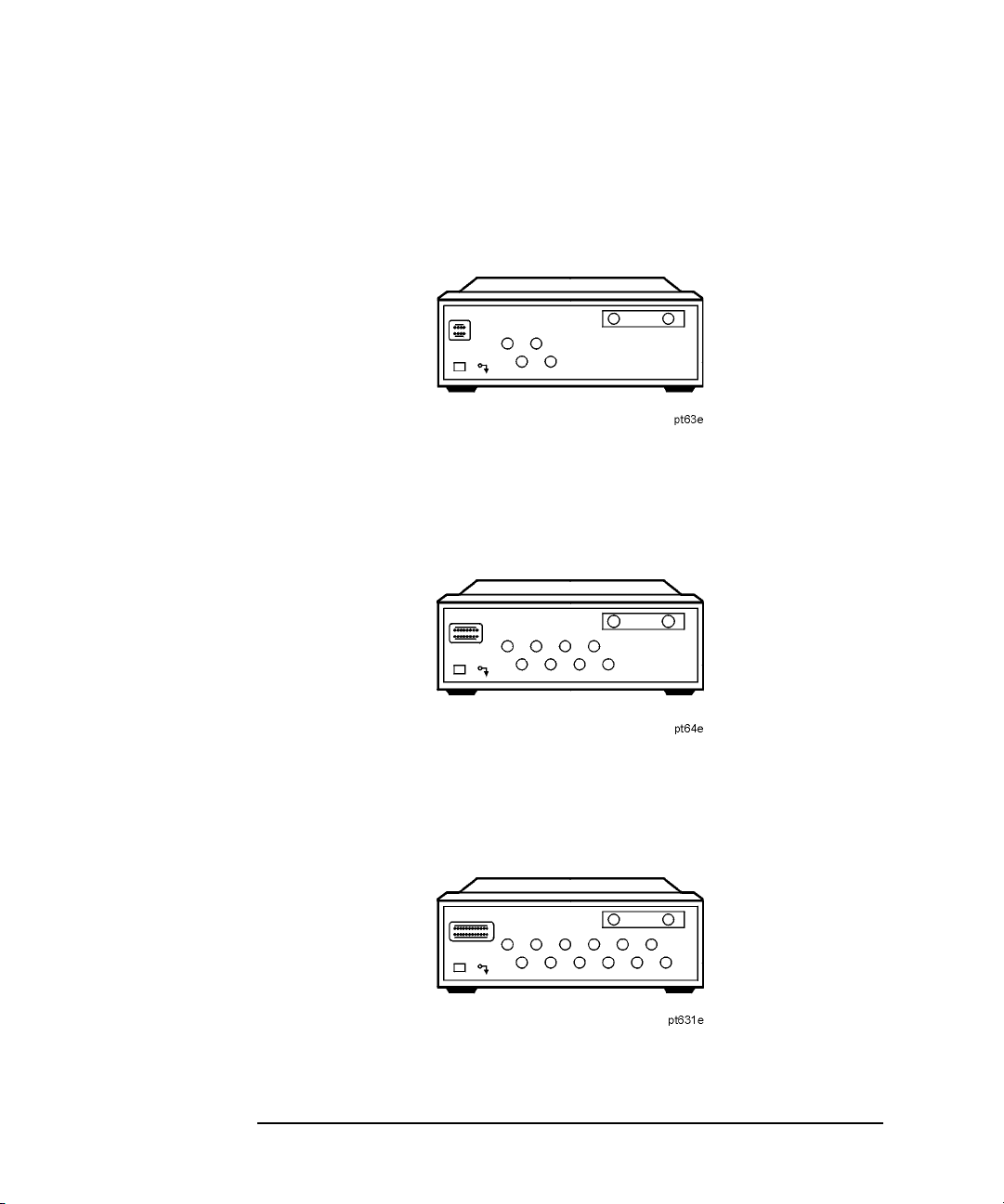
Figure 1-1 87050E Multiport Test Set — Three Versions
87050E Option 004 — Four Port Test Set
87050E Option 008 — Eight Port Test Set
87050E Option 012 — Twelve Port Test Set
1-8 Chapter 1

Figure 1-2 87075C Multiport Test Set — Two Versions
87075C Option 006 — Six Port Test Set
87075C Option 012 — Twelve Port Test Set
Introduction and Installation
Installation
Chapter 1 1-9

Introduction and Installation
Installation
Step 1. Check the Shipment
After you have unpacked your test set, keep the packaging materials to
use if your instrument should need to be returned for maintenance or
repair.
NOTE The packaging material is designed to protect the test set from damage
that can happen during shipping. Returning the test set in anything
other than the original packaging may result in non-warranted damage.
Check the items received against Table 1-1 on page 1-11 to make sure
that you received everything.
Inspect the test set and all accessories for any signs of damage that may
have occurred during shipment. If your test set or any accessories appear
to be damaged or missing, call Agilent Technologies. Refer to page 35 for
contact information.
1-10 Chapter 1

Table 1-1 Test Set Accessories Supplied
Introduction and Installation
Installation
Item
No.
Description Quantity Part Number
1 Power Cord 1 See Figure 6-5 on
page 6-9.
2 Type-N Cable (Analyzer to test set’s
REFLECTION Port)
1
1 (75 Ω) 87075-60026
(50 Ω) 87050-60058
3 Type-N Cable (Analyzer to test set’s
TRANSMISSION Port)
1
1 (75 Ω) 87075-60028
(50 Ω) 87050-60060
4 Type-N Cable (Analyzer to test set’s
REFLECTION Port)
2
1 (75 Ω) 87075-60027
(50 Ω) 87050-60059
5 Type-N Cable (Analyzer to test set’s
TRANSMISSION Port)
2
1 (75 Ω) 87075-60029
(50 Ω) 87050-60061
6 Parallel Port Interface Cable 1 8120-6818
7 87050E and 87075C User's and Service
1
87050-90026
Guide for 871x Network Analyzers
87075C only: 87075C User's and Service
Guide for E506x Network Analyzers
1
87075-90027
8 Test Set Calibration Disk 1 N/A
9 Performance Test Programs Disks
1 08714-60049
(DOS and LIF formats)
10 CD-ROM 1 08714-90051
1. Not to be used with a rack-mounted system or if the analyzer has had its bottom
feet removed. See Figure 1-7 on page 1-19 to see how these cables are to be con-
nected.
2. You will only receive these cables if you ordered Option 1CM (rack mount kit). Use
these cables if you are rack-mounting your system, or if the bottom feet of the analyzer have been removed. See Figure 1-7 on page 1-19 for information on how to
connect these cables.
Chapter 1 1-11

Introduction and Installation
Installation
Figure 1-3 Test Set Accessories Supplied
Step 2. Determine Network Analyzer Compatibility
The 87050E multiport test set is designed for use with 8712ET/ES and
8714ET/ES RF network analyzers, 50 Ω impedance.
The 87075C multiport test set is designed for use with
8711C/12C/13C/14C or 8712ET/ES and 8714ET/ES RF network
analyzers, 75 Ω impedance (Option 1EC).
The basic function of the 87050E and the 87075C multiport test sets is
identical. However, their impedance and specifications are different.
1-12 Chapter 1

Introduction and Installation
Installation
If you are using a C-series analyzer, refer to “If You Are Using an
8711C/12C/13C/14C Analyzer” on page 1-6.
Check the Firmware Revision
The firmware in your E-series analyzer must be revision E.06.00 or later.
The firmware revision is displayed when you first power up the analyzer,
and can also be viewed by pressing
Instrument Info
If your analyzer does not have firmware revision E.06.00 or later, then
you must upgrade to the latest revision of firmware. You can perform this
upgrade yourself. The current firmware is available as a set of floppy
disks. To order, contact Agilent Technologies. Refer to page 35 for contact
information.
The current firmware revision may also be downloaded, free of charge,
through the internet. There is a link to the download site at the following
URL: http://www.agilent.com/find/enasupport
CAUTION When upgrading firmware from E.05.xx to E.06.xx, it is necessary to
save the correction constants on a floppy disk before loading the new
version of firmware.
.
SYSTEM OPTIONS Service
Chapter 1 1 -13

Introduction and Installation
Installation
Step 3. Connect the Test Set to the Analyzer
For using your system on a bench, configure and connect the two
instruments as shown in Figure 1-4. Use the parallel cable that was
shipped with the multiport test set to connect to the analyzer as shown.
If you will be installing your system in a rack, read “Installing the
System in a Rack,” next in this section, before connecting the test set to
the analyzer.
Figure 1-4 System Configuration
1-14 Chapter 1

Introduction and Installation
Installation
Installing the System in a Rack
Use only the recommended rack mount kit for the network analyzer
(Option 1CM when ordered with the analyzer, or part number
08712-60036 when ordered separately): it needs side support rails. Do
not attempt to mount the analyzer by the front panel (handles) only. The
recommended rack mount kit allows you to mount the analyzer with or
without handles.
The rack mount kit for the test set is Option 1CM when ordered with the
test set, or part number 5063-9214 when ordered separately.
NOTE There are special semi-rigid cables that should be used to connect the
analyzer’s test ports to the test set’s REFLECTION and
TRANSMISSION ports when used in a rack (or a bench configuration
where the analyzer’s bottom feet have been removed). These cables were
shipped with your analyzer if you ordered Option 1CM. If you order the
rack mount kit separately, you will need to order these special cables
separately also. See Table 1-1 on page 1-11 for part numbers.
To install your system in an 85043D rack, follow the instructions in the
rack manual.
CAUTION When installing your system in other racks, improper installation may
cause shock hazards, overheating, dust contamination, and inferior
system performance. For support details and information about
installation and warranty, call Agilent Technologies. Refer to page 35 for
the nearest office.
CAUTION When installing the system in a cabinet, the convection into and out of
the system must not be restricted. The ambient temperature (outside the
cabinet) must be less than the maximum operating temperature of the
system by 4 °C for every 100 watts dissipated in the cabinet. If the total
power dissipated in the cabinet is greater than 800 watts, then forced
convection must be used.
Chapter 1 1 -15

Introduction and Installation
Installation
Step 4. Satisfy Electrical and Environmental Requirements
NOTE Refer to your network analyzer’s User’s Guide for information on
electrical and environmental requirements for your network analyzer.
1. The line power module on your multiport test set has an autoranging
input. It is designed to be used with an ac power source with a
nominal voltage of either 115 V or 230 V.
2. Ensure the available ac power source meets the following
requirements:
Nominal Range
Frequency: 50/60 Hz 47–63 Hz
Line Voltage: 100/115 V or 230/240 V 90–264 V
Power 45 W max
CAUTION This product has an autoranging line-voltage input. Be sure the supply
voltage is within the specified range.
If the ac line voltage does not fall within these ranges, an
autotransformer that provides third-wire continuity to earth ground
should be used.
3. Ensure the operating environment meets the following requirements
for safety:
• indoor use
• altitude up to 15,000 feet (4,572 meters)
• temperature 0 °C to 55 °C
• maximum relative humidity 80% for temperatures up to 31 °C
decreasing linearly to 50% relative humidity at 40 °C
• use only in INSTALLATION CATEGORY II, and POLLUTION
DEGREE 2, per IEC 1010 and 664 respectively
1-16 Chapter 1
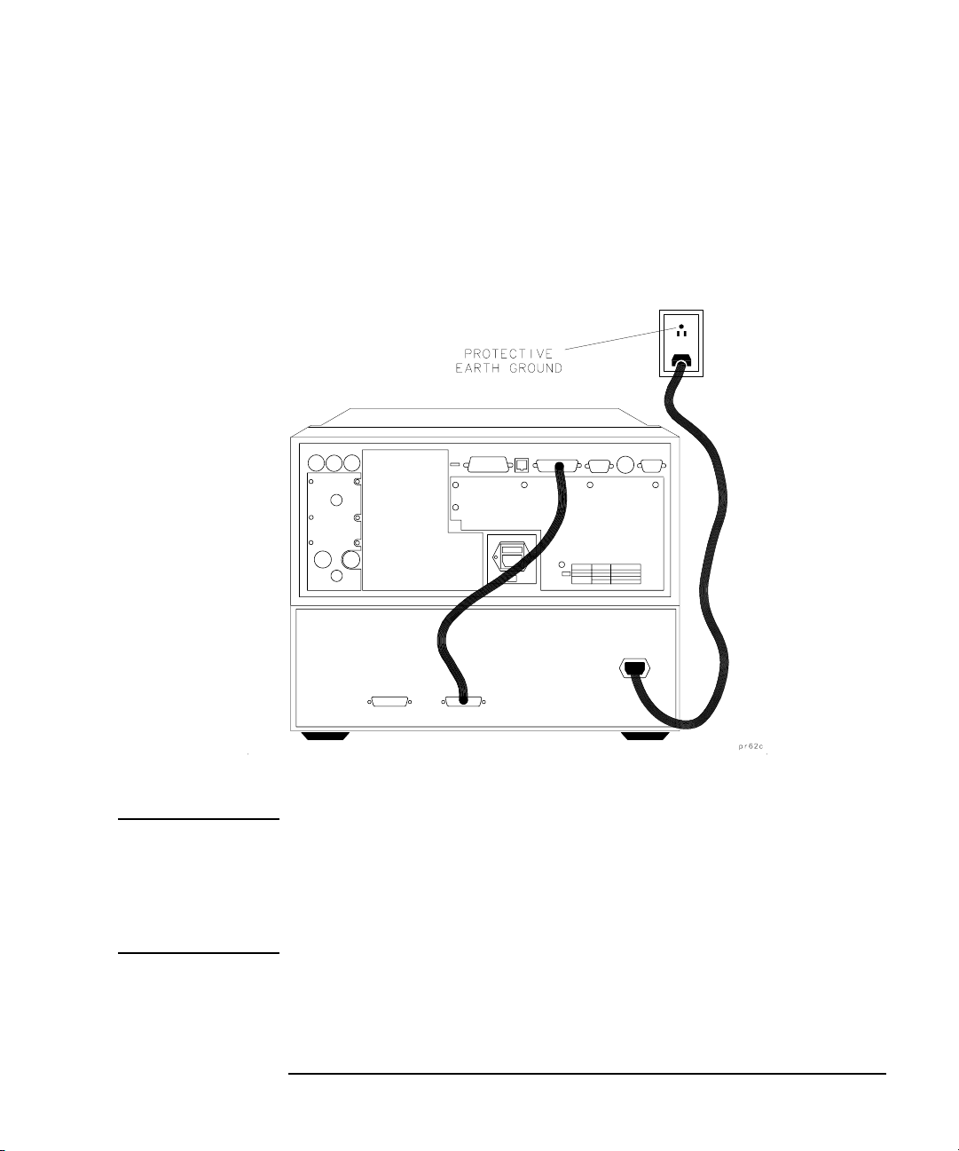
4. Verify that the power cable is not damaged, and that the power source
outlet provides a protective earth ground contact. Note that the
following illustration depicts only one type of power source outlet.
Refer to Figure 6-5 on page 6-9 to see the different types of power cord
plugs that can be used with your test set.
Figure 1-5 Protective Earth Ground
Introduction and Installation
Installation
WARNING This is a Safety Class I product (provided with a protective
earthing ground incorporated in the power cord). The mains
plug shall only be inserted in a socket outlet provided with a
protective earth contact. Any interruption of the protective
conductor, inside or outside the instrument, is likely to make the
instrument dangerous. Intentional interruption is prohibited.
Chapter 1 1 -17

Introduction and Installation
Installation
5. Ensure there are at least two inches of clearance around the sides and
back of the test set or the system cabinet.
Figure 1-6 Ventilation Clearance Requirements
6. Set up a static-safe workstation. Electrostatic discharge (ESD) can
damage or destroy components.
• table mat with earth ground wire:
part number 9300-0797
• wrist-strap cord with 1 Meg Ohm
resistor:
part number 9300-0980
•wrist-strap:
part number 9300-1367
• heel straps:
part number 9300-1308
• floor mat
1-18 Chapter 1
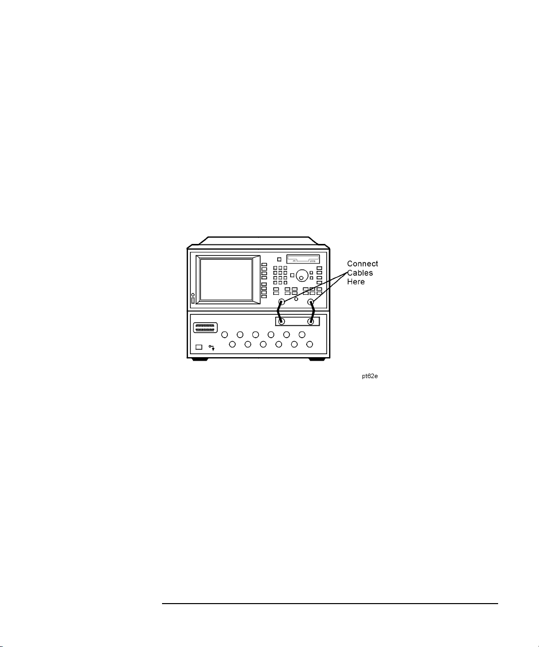
Step 5. Activate the Test Set and Check the System Operation
1. Connect the semi-rigid cables that were shipped with your test set as
shown in Figure 1-7. Check Table 1-1 on page 1-11 to be sure that you
are using the correct cables with your system configuration (the
cables you use will be different depending on whether you are using a
bench system configuration—as shown in Figure 1-7—or a rack
configuration).
Figure 1-7 Connect the Front Panel RF Cables
Introduction and Installation
Installation
Chapter 1 1 -19

Introduction and Installation
Installation
NOTE Steps 2 and 3 must be performed before you can use your network
analyzer to control the multiport test set.
2. Turn on the test set.
3. Turn on the analyzer and press
Switching Test Set Multiport
. Toggle to ON.
SYSTEM OPTIONS System Config
4. The operator’s check should be performed on the system to provide a
high degree of confidence that the system is working properly. Refer
to Chapter 2, “Getting Started,” for instructions on how to perform
the operator’s check.
5. After performing the operator’s check, you should connect any
peripheral devices you will be using with your system. Refer to “Step
6. Connect Peripheral Devices,” next in this chapter.
1-20 Chapter 1
 Loading...