


Agilent 8702E
Lightwave Component Analyzer
Installation Guide

© Copyright
Agilent Technologies 2001
All Rights Reserved. Reproduction, adaptation, or translation without prior written
permission is prohibited,
except as allowed under copyright laws.
Agilent Part No. 08702-91031
Printed in USA
March 2001
Agilent Technologies
Lightwave Division
3910 Brickway BoulevardSanta Rosa, CA 95403, USA
Notice.
The information contained in
this document is subject to
change without notice. Companies, names, and data used
in examples herein are fictitious unless otherwise noted.
Agilent Technologies makes
no warranty of any kind with
regard to this material, including but not limited to, the
implied warranties of merchantability and fitness for a
particular purpose. Agilent
Technologies shall not be liable for errors contained herein
or for incidental or consequential damages in connection with the furnishing,
performance, or use of this
material.
Restricted Rights Legend.
Use, duplication, or disclosure by the U.S. Government
is subject to restrictions as set
forth in subparagraph (c) (1)
(ii) of the Rights in Technical
Data and Computer Software
clause at DFARS 252.227-7013
for DOD agencies, and subparagraphs (c) (1) and (c) (2)
of the Commercial Computer
Software Restricted Rights
clause at FAR 52.227-19 for
other agencies.
Warranty.
This Agilent Technologies
instrument product is warranted against defects in
material and workmanship for
a period of one year from date
of shipment. During the warranty period, Agilent Technologies will, at its option, either
repair or replace products
which prove to be defective.
For warranty service or repair,
this product must be returned
to a service facility designated by Agilent Technologies. Buyer shall prepay
shipping charges to Agilent
Technologies and Agilent
Technologies shall pay shipping charges to return the
product to Buyer. However,
Buyer shall pay all shipping
charges, duties, and taxes for
products returned to Agilent
Technologies from another
country.
Agilent Technologies warrants that its software and
firmware designated by Agilent Technologies for use with
an instrument will execute its
programming instructions
when properly installed on
that instrument. Agilent Technologies does not warrant that
the operation of the instrument, or software, or firmware
will be uninterrupted or errorfree.
Limitation of Warranty.
The foregoing warranty shall
not apply to defects resulting
from improper or inadequate
maintenance by Buyer, Buyersupplied software or interfacing, unauthorized modification or misuse, operation
outside of the environmental
specifications for the product,
or improper site preparation
or maintenance.
No other warranty is
expressed or implied. Agilent
Technologies specifically disclaims the implied warranties
of merchantability and fitness
for a particular purpose.
Exclusive Remedies.
The remedies provided herein
are buyer's sole and exclusive
remedies. Agilent Technologies shall not be liable for any
direct, indirect, special, incidental, or consequential damages, whether based on
contract, tort, or any other
legal theory.
Safety Symbols.
CAUTION
The
caution
sign denotes a
hazard. It calls attention to a
procedure which, if not correctly performed or adhered
to, could result in damage to
or destruction of the product.
Do not proceed beyond a caution sign until the indicated
conditions are fully understood and met.
WAR NI NG
The
warning
sign denotes a
hazard. It calls attention to a
procedure which, if not correctly performed or adhered
to, could result in injury or
loss of life. Do not proceed
beyond a warning sign until
the indicated conditions are
fully understood and met.
The instruction manual symbol. The product is marked with this
warning symbol when
it is necessary for the
user to refer to the
instructions in the
manual.
The laser radiation
symbol. This warning
symbol is marked on
products which have a
laser output.
The AC symbol is used
to indicate the
required nature of the
line module input
power.
The ON symbols are
|
used to mark the positions of the instrument
power line switch.
The OFF symbols
❍
are used to mark the
positions of the instrument power line
switch.
The CE mark is a registered trademark of
the European Community.
The CSA mark is a registered trademark of
the Canadian Standards Association.
The C-Tick mark is a
registered trademark
of the Australian Spectrum Management
Agency.
This text denotes the
ISM1-A
instrument is an
Industrial Scientific
and Medical Group 1
Class A product.
Typographical Conventions.
The following conventions are
used in this book:
Key type
for keys or text
located on the keyboard or
instrument.
Softkey type
for key names that
are displayed on the instrument’s screen.
Display type
for words or
characters displayed on the
computer’s screen or instrument’s display.
User type
for words or charac-
ters that you type or enter.
Emphasis
type for words or
characters that emphasize
some point or that are used as
place holders for text that you
type.
ii
Installation at a Glance
Installation at a Glance
The procedures in this book provide step-by-step instructions for installing
the Agilent 8702E.
Be sure to verify the Agilent 8702E’s performance
Chapter 2, “Automated Verification”, Chapter 3, “Manual Verification”, and
Chapter 4, “Performance Tests” provide verification procedures and perfor-
mance tests. Verification procedures are intended to provide a high level of
confidence that the instrument is operating properly. Two versions of verification procedures are provided: automated and manual. The performance tests,
along with the verification tests, provide the same quality of performance testing that is done at the factory. Chapter 5, “Automated Verification – Option
011” and Chapter 6, “Performance Tests – Option 011” provide verification
procedures and performance tests for the Agilent 8702E Option 011.
Agilent Technologies recommends that you verify your analyzer measurement
system every six months. Agilent Technologies also suggests that you get your
verification kit recertified annually. Refer to
tion Kit Operating and Service Manual
Agilent 85029B 7 mm Verifica-
for more information.
These system verification procedures do
(75 ohm analyzers).
not
apply to analyzers with Option 075
General Safety Considerations
This product has been designed and tested in accordance with IEC Publication 61010-1, Safety Requirements for Electrical Equipment for Measurement,
Control and Laboratory Use, and has been supplied in a safe condition. The
instruction documentation contains information and warnings that must be
followed by the user to ensure safe operation and to maintain the product in a
safe condition.
iii

General Safety Considerations
WARNING
WARNING
WARNING
WARNING
WARNING
If this instrument is not used as specified, the protection provided by
the equipment could be impaired. This instrument must be used in a
normal condition (in which all means for protection are intact) only.
To prevent electrical shock, disconnect the Agilent 8702E from mains
before cleaning. Use a dry cloth or one slightly dampened with water
to clean the external case parts. Do not attempt to clean internally.
This is a Safety Class 1 product (provided with a protective earthing
ground incorporated in the power cord). The mains plug shall only be
inserted in a socket outlet provided with a protective earth contact.
Any interruption of the protective conductor inside or outside of the
product is likely to make the product dangerous. Intentional
interruption is prohibited.
No operator serviceable parts inside. Refer servicing to qualified
personnel. To prevent electrical shock, do not remove covers.
For continued protection against fire hazard, replace line fuse only
with same type and ratings, (type T 0.315A/250V for 100/120V
operation and 0.16A/250V for 220/240V operation). The use of other
fuses or materials is prohibited. Verify that the value of the linevoltage fuse is correct.
• For 100/120V operation, use an IEC 127 5×20 mm, 0.315 A, 250 V, Agilent
part number 2110-0449.
CAUTION
CAUTION
• For 220/240V operation, use an IEC 127 5×20 mm, 0.16 A, 250 V, Agilent
Technologies part number 2110-0448.
Before switching on this instrument, make sure that the line voltage selector
switch is set to the line voltage of the power supply and the correct fuse is
installed. Assure the supply voltage is in the specified range.
This product is designed for use in INSTALLATION CATEGORY II and
POLLUTION DEGREE 2, per IEC 1010 and 664 respectively.
iv

Certification
CAUTION
CAUTION
CAUTION
CAUTION
VENTILATION REQUIREMENTS: When installing the product in a cabinet, the
convection into and out of the product must not be restricted. The ambient
temperature (outside the cabinet) must be less than the maximum operating
temperature of the product by 4°C for every 100 watts dissipated in the
cabinet. If the total power dissipated in the cabinet is greater than 800 watts,
then forced convection must be used.
Always use the three-prong ac power cord supplied with this instrument.
Failure to ensure adequate earth grounding by not using this cord may cause
instrument damage.
connect ac power until you have verified the line voltage is correct.
Do not
Damage to the equipment could result.
This instrument has autoranging line voltage input. Be sure the supply voltage
is within the specified range.
Certification
Agilent Technologies certifies that this product met its published specifications at the time of shipment from the factory. Agilent Technologies further
certifies that its calibration measurements are traceable to the United States
National Institute of Standards and Technology, to the extent allowed by the
Institute’s calibration facility, and to the calibration facilities of other International Standards Organization members.
Assistance
Product maintenance agreements and other customer assistance agreements
are available for Agilent Technologies products. For any assistance, contact
your nearest Agilent Technologies Service Office.
v

Assistance
vi

Contents
Installation at a Glance iii
General Safety Considerations iii
Certification v
Assistance v
1 Installing the Agilent 8702E
Step 1. Inspect the Shipment 1-3
Step 2. Set up Static-Safe Workstation 1-4
Step 3. Option 1D5, Connect the Frequency Reference 1-6
Step 4. Check the Fuse and Voltage Selection 1-7
Step 5. Connect the Line-Power Cable 1-9
Step 6. Connect a Keyboard 1-11
Step 7. Turn on the Agilent 8702E 1-12
Step 8. Connect a Printer or Plotter 1-13
Step 9. If You Connect a Printer 1-14
Step 10. If You Connect a Plotter 1-15
Step 11. Set the Clock 1-16
Step 12. Check the Operation 1-17
Step 13. Check the Operation (Option 011) 1-22
Step 14. Copy the EEPROM Disk 1-27
2 Automated Verification
3Manual Verification
4 Performance Tests
5 Automated Verification – Option 011
Agilent 8702E Option 011 and Agilent 85046A/47A System Verification 5-4
Agilent 8702E Option 011 and Agilent 85044A System Verification 5-13
6 Performance Tests – Option 011
7 If You Encounter a Problem
If the display does not light 7-2
If the fan does not run 7-3
If data entry keys don’t respond 7-4
Contents-1

Contents
If there is no RF signal 7-4
Returning the Instrument for Service 7-6
Agilent Technologies Service Offices 7-9
Contents-2

1
Step 1. Inspect the Shipment 1-3
Step 2. Set up Static-Safe Workstation 1-4
Step 3. Option 1D5, Connect the Frequency Reference 1-6
Step 4. Check the Fuse and Voltage Selection 1-7
Step 5. Connect the Line-Power Cable 1-9
Step 6. Connect a Keyboard 1-11
Step 7. Turn on the Agilent 8702E 1-12
Step 8. Connect a Printer or Plotter 1-13
Step 9. If You Connect a Printer 1-14
Step 10. If You Connect a Plotter 1-15
Step 11. Set the Clock 1-16
Step 12. Check the Operation 1-17
Step 13. Check the Operation (Option 011) 1-22
Step 14. Copy the EEPROM Disk 1-27
Installing the Agilent 8702E

Installing the Agilent 8702E
Installing the Agilent 8702E
Installing the Agilent 8702E
The instructions in this chapter show you how to install your Agilent 8702E.
You should be able to finish these procedures in about ten to twenty minutes.
Refer to “Specifications and Regulatory Information”, in the
Reference
ture.
If you should ever need to clean the cabinet, use a damp cloth only.
manual, for information on operating conditions such as tempera-
Agilent 8702E
WARNING
CAUTION
CAUTION
CAUTION
Any interruption of the protective conductor inside or outside of the
product is likely to make the product dangerous. Intentional
interruption is prohibited.
This product has autoranging line voltage input. Be sure the supply voltage is
within the specified range.
VENTILATION REQUIREMENTS: When installing the product in a cabinet, the
convection into and out of the product must not be restricted. The ambient
temperature (outside the cabinet) must be less than the maximum operating
temperature of the product by 4°C for every 100 watts dissipated in the
cabinet. If the total power dissipated in the cabinet is greater than 800 watts,
then forced convection must be used.
This product is designed for use in INSTALLATION CATEGORY II and
POLLUTION DEGREE 2, per IEC 1010 and 664 respectively.
1-2
Installing the Agilent 8702E
Step 1. Inspect the Shipment
Step 1. Inspect the Shipment
1
Verify that all components ordered have arrived by comparing the shipping
forms to the original purchase order. Inspect all shipping containers.
If your shipment is damaged or incomplete, save the packing materials and notify both the shipping carrier and the nearest Agilent Technologies service office. Agilent Technologies will arrange for repair or replacement of damaged or
incomplete shipments without waiting for a settlement from the transportation
company. Notify the Agilent Technologies customer engineer of any problems.
WARNING
The Agilent 8702E weighs approximately 75 pounds (34 kilograms).
Use correct lifting techniques.
The PORT 1 connector moves.
This is
accessories can be more easily connected to the instrument.
2
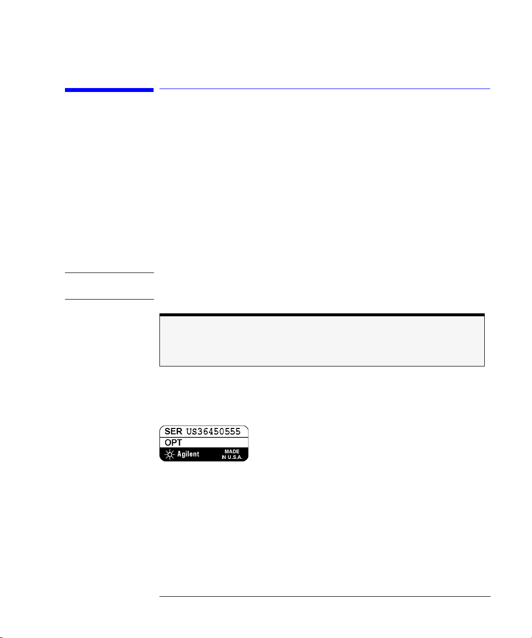
Make sure that the serial number and options listed on the instrument’s rearpanel label match the serial number and options listed on the shipping
document.
Figure 1-1. Serial Number Label
a defect. This connector is designed to move so that test sets and other
not
1-3
Installing the Agilent 8702E
Step 2. Set up Static-Safe Workstation
Step 2. Set up Static-Safe Workstation
Electrostatic discharge (ESD) can damage or destroy the input circuits of the
Agilent 8702E. ESD can also damage or destroy electronic components that
you are measuring. All work should be performed at a static-safe work station.
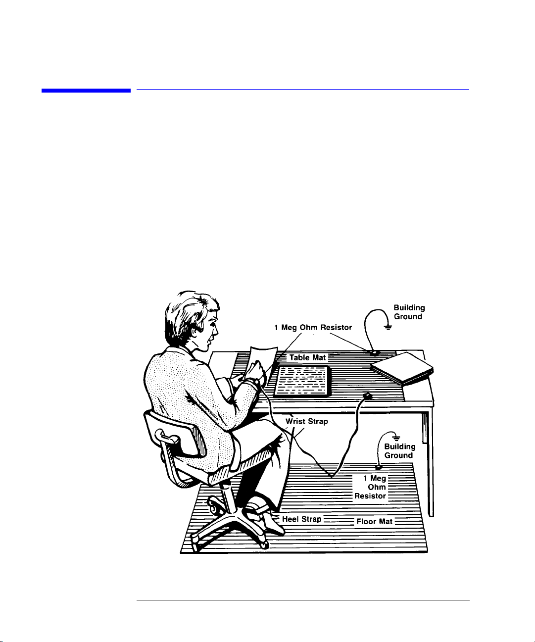
The following figure shows an example of a static-safe work station (without
the instrument) using two types of ESD protection:
• Conductive table-mat and wrist-strap combination.
• Conductive floor-mat and heel-strap combination.
1-4

Installing the Agilent 8702E
Step 2. Set up Static-Safe Workstation
Both types, when used together, provide a significant level of ESD protection.
Of the two, only the table-mat and wrist-strap combination provides adequate
ESD protection when used alone.
To ensure user safety, the static-safe accessories must provide at least 1 MΩ of
isolation from ground. Refer to Ta ble 1- 1 for information on ordering staticsafe accessories.
WARNING
These techniques for a static-safe work station should not be used
when working on circuitry with a voltage potential greater than
500 volts.
Reducing ESD Damage
The following suggestions may help reduce ESD damage that occurs during
testing and servicing operations.
• Personnel should be grounded with a resistor-isolated wrist strap before removing any assembly from the unit.
• Be sure all instruments are properly earth-grounded to prevent a buildup of
static charge.
Table 1-1. Static-Safe Accessories
Agilent Part
Number
9300-0797
9300-0980 Wrist-strap cord 1.5 m (5 ft)
9300-1383 Wrist-strap, color black, stainless steel, without cord, has four adjustable
Description
3M static control mat 0.6 m
wire. (The wrist-strap and wrist-strap cord are not included. They must be
ordered separately.)
links and a 7 mm post-type connection.
× 1.2 m (2 ft× 4 ft) and 4.6 cm (15 ft) ground
9300-1169 ESD heel-strap (reusable 6 to 12 months).
1-5
Installing the Agilent 8702E
Step 3. Option 1D5, Connect the Frequency Reference
Step 3. Option 1D5, Connect the Frequency
Reference
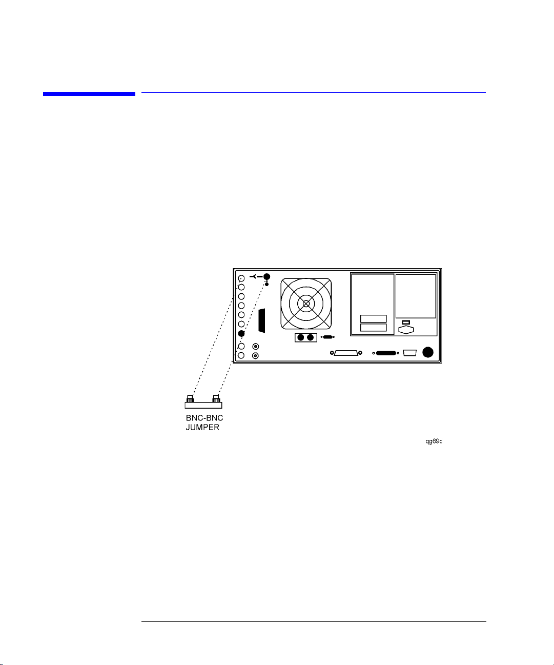
If your instrument has the optional high stability frequency reference
installed, connect the jumper cable on the Agilent 8702E rear panel as shown
in Figure 1-2.
Figure 1-2. Jumper Cable Connection
1-6
Installing the Agilent 8702E
Step 4. Check the Fuse and Voltage Selection
Step 4. Check the Fuse and Voltage Selection
1
Locate the line-input connector on the instrument’s rear panel.
2
Disconnect the line-power cable if it is connected.
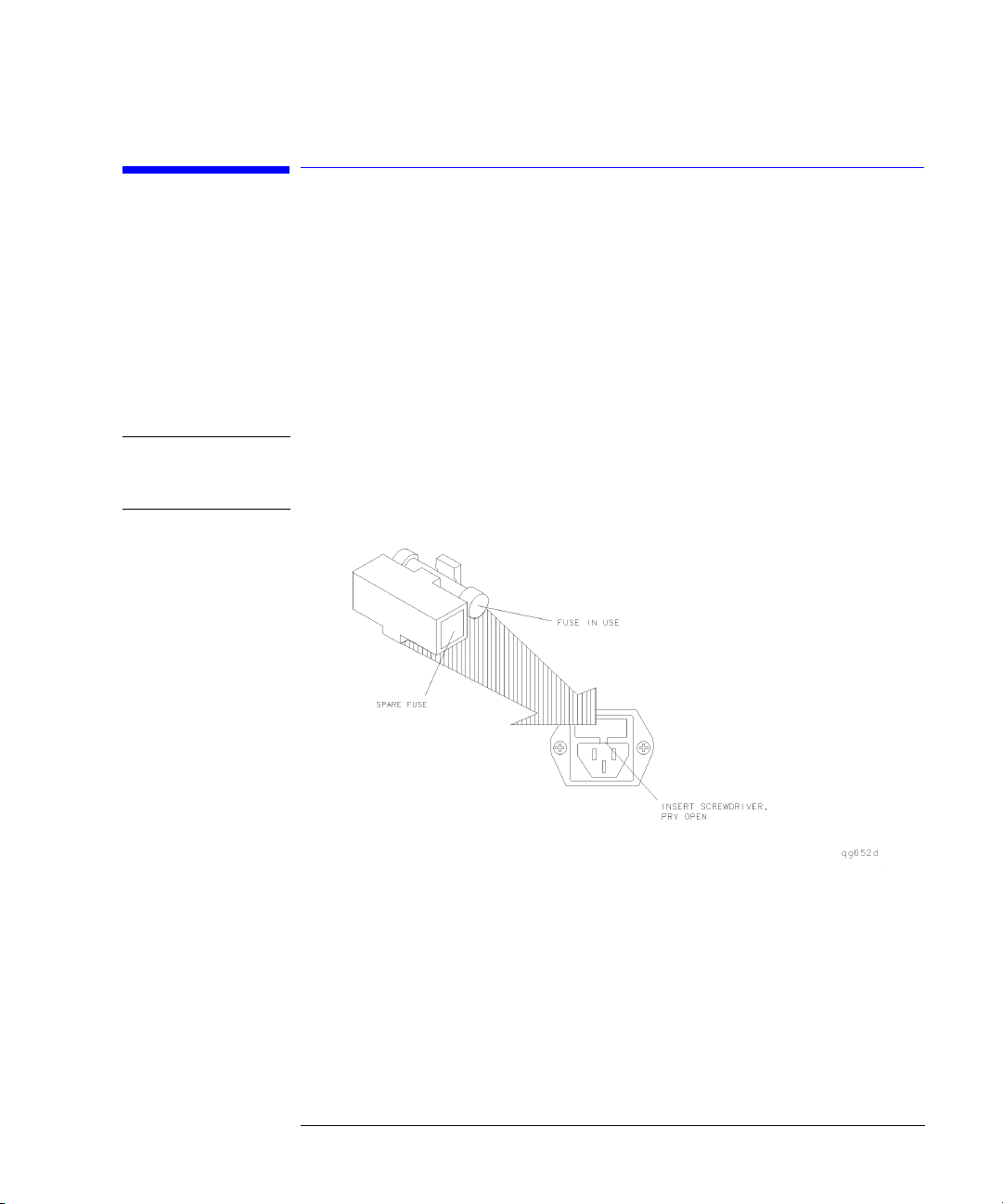
3
Use a small flat-blade screwdriver to open the pull-out fuse drawer.
WARNING
The power cord is connected to internal capacitors that may remain
live for 10 seconds after you disconnect the cord from the power
supply.
Figure 1-3. Line Fuse Removal and Replacement
4
Verify that the value of the line-voltage fuse in the pull-out drawer is correct.
Th e recom mende d fu se is a n IEC 12 7 5×20 mm, 3A, 250 V, Agilent part number
2110-0780.
Notice that an extra fuse is provided in a drawer located on the fuse holder.
1-7

Installing the Agilent 8702E
Step 4. Check the Fuse and Voltage Selection
WARNING
For continued protection against fire hazard, replace line fuse only
with same type and ratings, (type T 3A/250V for 100/240V operation).
The use of other fuses or materials is prohibited.
5
Set the rear panel line-voltage selector to the position that corresponds to the
AC power source. Refer to Figure 1-4.
Figure 1-4. Line Voltage Selector
Table 1-2. Line Power Requirements
Power: 115 VAC: 50 WATTS MAX.
230 VAC: 50 WATTS MAX.
Voltage nominal: 115 VAC / 230 VAC
range 115 VAC: 90
range 230 VAC: 198
Frequency nominals: 50 Hz / 60 Hz
range: 47
1-8
−132 V
−254 V
−63 Hz

Installing the Agilent 8702E
Step 5. Connect the Line-Power Cable
Step 5. Connect the Line-Power Cable
CAUTION
CAUTION
Always use the three-prong AC power cord supplied with this instrument.
Failure to ensure adequate earth grounding by not using this cord may cause
instrument damage.
Do
connect ac power until you have verified the line voltage is correct as
not
described in the following paragraphs. Damage to the equipment could result.
1
Connect the line-power cord to the instrument’s rear-panel connector. Refer to
Figure 1-5.
2
Connect the other end of the line-power cord to the power receptacle. Refer to
Figure 1-5.
Various power cables are available to connect the Agilent 8702E to ac power
outlets unique to specific geographic areas. The cable appropriate for the area
to which the Agilent 8702E is originally shipped is included with the unit. You
can order additional ac power cables for use in different geographic areas.
Refer to the
cables.
Agilent 8702E Reference
manual for a list of available power
1-9

Installing the Agilent 8702E
Step 5. Connect the Line-Power Cable
Figure 1-5. Power Cord Connection
1-10

Installing the Agilent 8702E
Step 6. Connect a Keyboard
Step 6. Connect a Keyboard
• If you plan to use a keyboard with your Agilent 8702E, connect it now to the
instrument’s rear-panel keyboard connector.
Figure 1-6. Rear Panel Peripheral Connections
1-11
Installing the Agilent 8702E
Step 7. Turn on the Agilent 8702E
Step 7. Turn on the Agilent 8702E
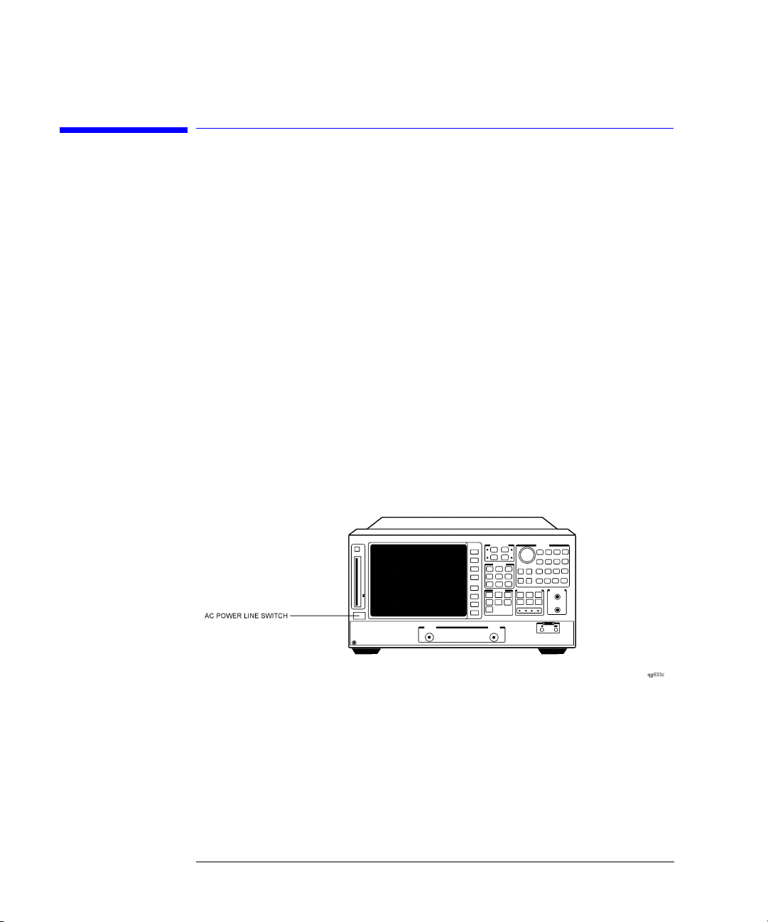
1
Press the front-panel
The front-panel
ply after the EMC filters and before other parts of the instrument.
2
If the Agilent 8702E fails to turn on properly, consider the following
possibilities:
• Is the line fuse good?
• Does the line socket have power?
• Is it plugged into the proper ac power source?
If the instrument still fails, return it to Agilent Technologies for repair. Refer to
“Returning the Instrument for Service” on page 7-6.
LINE
key. Refer to Figure 1-7.
LINE
switch disconnects the mains circuits from the mains sup-
Figure 1-7. Turning on the Instrument
1-12

Installing the Agilent 8702E
Step 8. Connect a Printer or Plotter
Step 8. Connect a Printer or Plotter
1
Connect a printer or plotter to the corresponding interface port. Refer to
Figure 1-6 on page 1-11 for the appropriate rear panel connection.
Printer Interface Recommended Cable
Parallel Agilent 92284A
Serial Agilent 24542G
GPIB Agilent 10833A/B/D
2
If you are using the parallel interface, press
LOCAL
and then
PARALLEL
until
appears.
GPIO
The
selection dedicates the parallel port for general purpose I/O. The Agilent 8702E controls the data input or output through the sequencing capability
of the instrument.
3
If you are using a GPIB printer or plotter, press
LOCAL
SYSTEM CONTROLLER
,
set up the Agilent 8702E as the controller.
COPY
to
1-13

Installing the Agilent 8702E
Step 9. If You Connect a Printer
Step 9. If You Connect a Printer
1
2
3
LOCAL
Press
SET ADDRESSES, PRINTER PORT
,
.
Press the key that corresponds to the printer interface:
port), or
If you selected
SERIAL
(serial port).
GPIB
, the GPIB address is active so you can then set the address
GPIB, PARAL LEL
of your printer. The default GPIB printer address is 1.
4
If you select
SERIAL
, adjust the Agilent 8702E’s baud rate and handshaking
protocol:
a
PRINTER BAUD RATE
Press
, and use the up and down arrow front-panel keys to
select the baud rate.
b
Set the transmission control,
XON/XOFF
or
DTR/DSR
(equal to the transmission control set on the peripher-
XMIT CNTRL
(handshaking protocol) to either
al).
XON/XOFF
selects software handshaking.
DTR/DSR
selects hardware
handshaking. Consult the printer’s manual for the proper settings.
5
Press
ThinkJet
•
DeskJet
•
LaserJet
•
PaintJet
•
PRNTR TYPE
(QuietJet)
(except for HP
until the correct printer choice appears:
1
DeskJet 540)
(parallel
Epson-P2
•
DJ540
•
1. HP is a registered trademark of Hewlett-Packard Company.
1-14
(printers that conform to the ESC.P2 printer control language)
(converts 100 dpi raster information to 300 dpi raster format)

Step 10. If You Connect a Plotter
Installing the Agilent 8702E
Step 10. If You Connect a Plotter
1
2
3
4
5
LOCAL
Press
Press the key that corresponds to the plotter interface:
port), or
If you selected
of your plotter. The default GPIB plotter address is 5.
If you select
protocol:
a
Press
select the baud rate.
b
Set the transmission control,
XON/XOFF
al).
XON/XOFF
handshaking. Consult the printer’s manual for the proper settings.
Press
•Choose
copy.
•Choose
to make your hardcopy.
SET ADDRESSES, PLOTTER PORT
,
SERIAL
(serial port).
GPIB
, the GPIB address is active so you can then set the address
SERIAL
, adjust the Agilent 8702E’s baud rate and handshaking
PLOTTER BAUD RATE
DTR/DSR
or
selects software handshaking.
PLTR TYPE
until the correct plotter selection appears:
PLTR TYPE [PLOTTER]
PLTR TYPE [HPGL PRT]
, and use the up and down arrow front-panel keys to
(equal to the transmission control set on the peripher-
if you will be using a plotter to make your hard-
if you will be using an HPGL compatible printer
.
XMIT CNTRL
GPIB, PARAL LEL
(handshaking protocol) to either
DTR/DSR
selects hardware
(parallel
1-15

Installing the Agilent 8702E
Step 11. Set the Clock
Step 11. Set the Clock
1
2
3
4
SYSTEM
Press
so the Agilent 8702E places the time and date on your hardcopies and disk
directories.
Press the appropriate softkey to set the time and date.
ROUND SECONDS
Press
TIME STAMP
Press
RETURN
.
SET CLOCK
,
to begin setting and activating the time stamp feature
when the time is exactly as you have set it.
so that ON is displayed on the softkey label. Then, press
Figure 1-8. Setting the Clock
1-16

Installing the Agilent 8702E
Step 12. Check the Operation
Step 12. Check the Operation
If your instrument is an Agilent 8702E Option 011, skip this step and continue
with “Step 13. Check the Operation (Option 011)” on page 1-22.
1
Turn off the
2
Locate the serial number and configuration options shown on the display.
Compare them to the shipment documents.
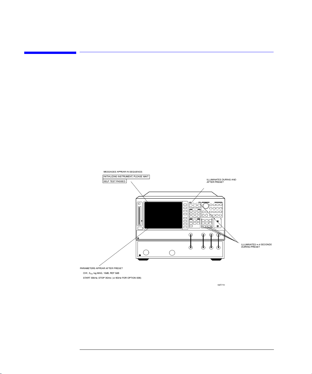
3
Press
Figure 1-9. Checking the Operation
LINE
power switch. Then, turn on the
PRESET
, and observe items shown in Figure 1-9.
LINE
power switch.
4
Connect the equipment as shown in Figure 1-10.
1-17

Installing the Agilent 8702E
Step 12. Check the Operation
Figure 1-10. Operation Check Connections
5
6
7
8
PRESET, SYSTEM
Press
SERVICE MENU, TESTS, EXTERNAL TESTS, EXECUTE TEST
,
Follow the prompts shown on the display, and then press
Press the up-arrow key,
the display. Then press
EXECUTE TEST
CONTINUE
.
, and then follow the prompts shown on
Connect the equipment as shown in Figure 1-11 and press
CONTINUE
PRESET
.
.
The test port return cable should have low-loss characteristics to avoid a degradation in frequency response at higher frequencies.
.
1-18
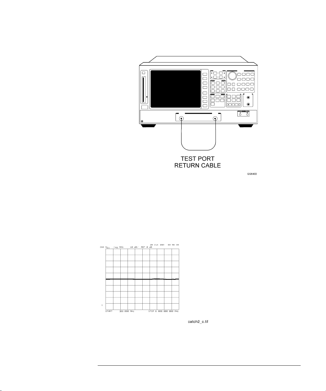
Figure 1-11. Transmission Mode Connections
Installing the Agilent 8702E
Step 12. Check the Operation
Press
CHAN2
to check the forward transmission mode for channel 2. Look at the
9
measurement trace displayed on the Agilent 8702E. It should be similar to the
trace shown in Figure 1-12.
The Agilent 8702E display shown in Figure 1-12 and Figure 1-13 are Agilent
8702E Option 006 displays (300 kHz to 6 GHz span).
Figure 1-12. Forward Transmission Display
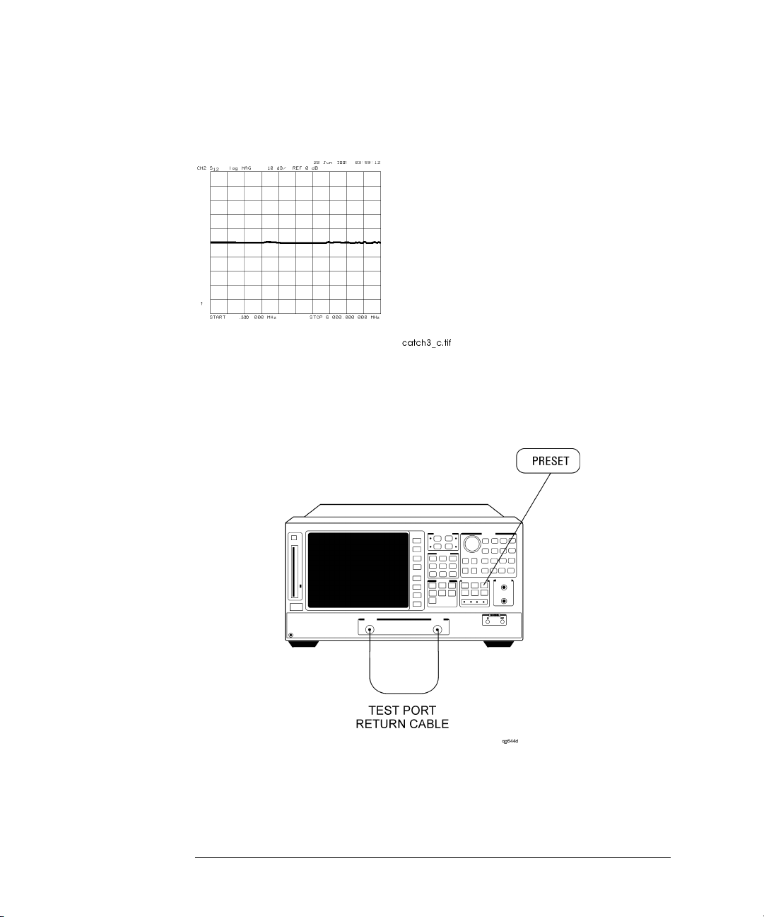
Press
MEAS
and then
Trans: E/E S12 REV
to check the reverse transmission mode
10
for channel 2. The measurement trace should be similar to the trace shown in
1-19
Installing the Agilent 8702E
Step 12. Check the Operation
Figure 1-13.
Figure 1-13. Reverse Transmission Display
11
Connect the equipment as shown in Figure 1-14 and press
PRESET
.
Figure 1-14. Transmission Load Match Connections
12
Look at the measurement trace displayed on the Agilent 8702E. It should be
similar to the trace displayed in Figure 1-15.
1-20
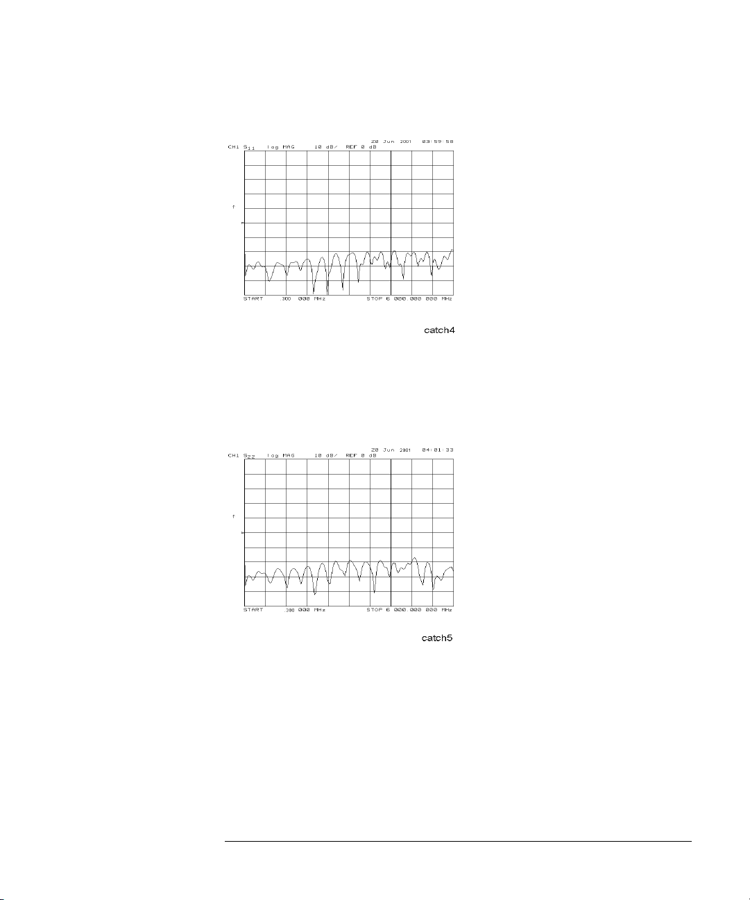
Figure 1-15. Forward Transmission Mode
Installing the Agilent 8702E
Step 12. Check the Operation
Press
MEAS,
Refl: E S22 REV
to check the reverse reflection mode for channel 1.
13
The measurement trace should be similar to Figure 1-16.
Figure 1-16. Reverse Reflection Mode
14
Continue with “Step 14. Copy the EEPROM Disk” on page 1-27.
1-21
Installing the Agilent 8702E
Step 13. Check the Operation (Option 011)
Step 13. Check the Operation (Option 011)
An Agilent 85047A S-parameter test set must be used when making measurements.
1
Turn off the
2
Locate the serial number and configuration options shown on the display.
Compare them to the shipment documents.
3
Press
Figure 1-17.
LINE
power switch. Then, turn on the
PRESET
, and observe that the analyzer is operating properly as shown in
LINE
power switch.
Figure 1-17. Checking the Operation (Option 011)
4
Connect the equipment as shown in Figure 1-18.
1-22
 Loading...